Experimental Evaluation of a Diesel Cogeneration System for Producing Power and Drying Aromatic Herbs


Abstract
:1. Introduction
2. Materials and Methods
2.1. Experimental Setup
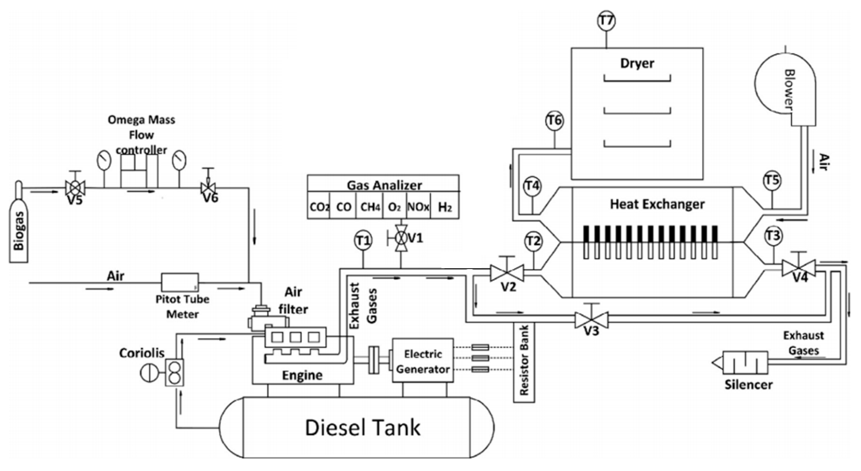
2.1.1. Cogeneration System
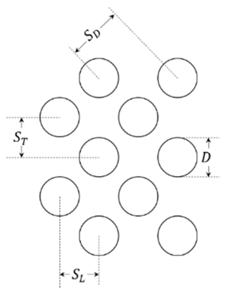
2.1.2. Thermosyphon Heat Exchanger Design
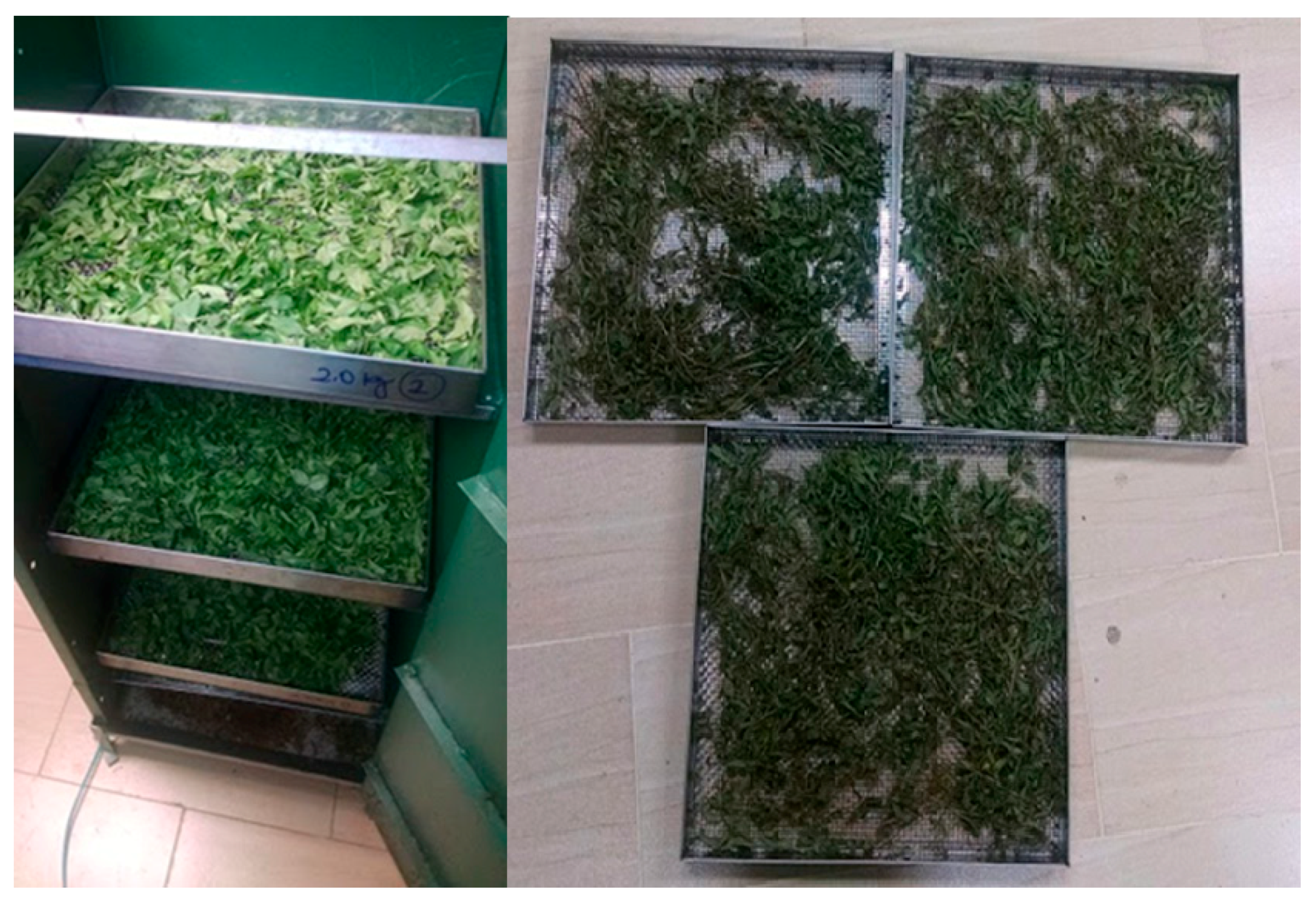
2.1.3. Aromatic Herbs Used for Drying
2.2. Experimental Procedure
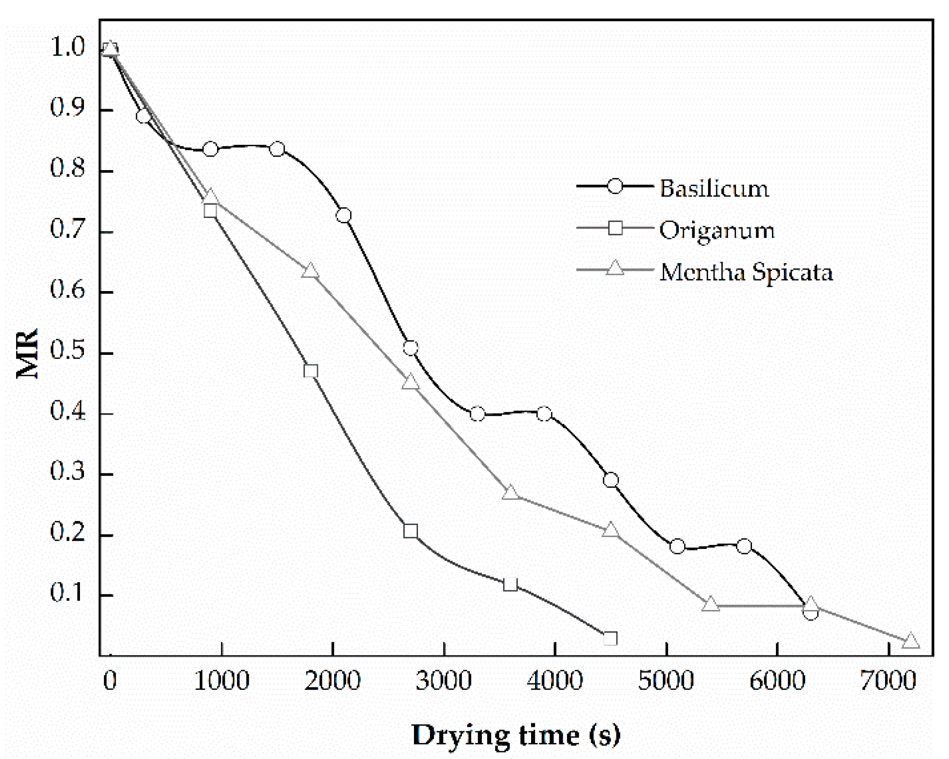
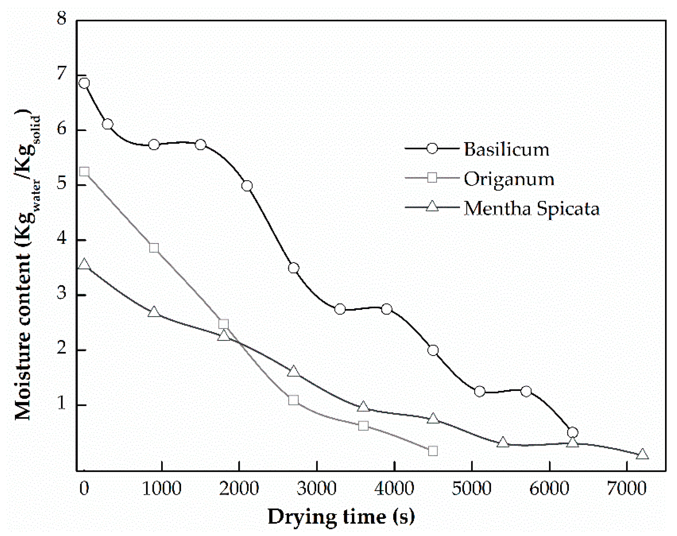
3. Results and Discussion
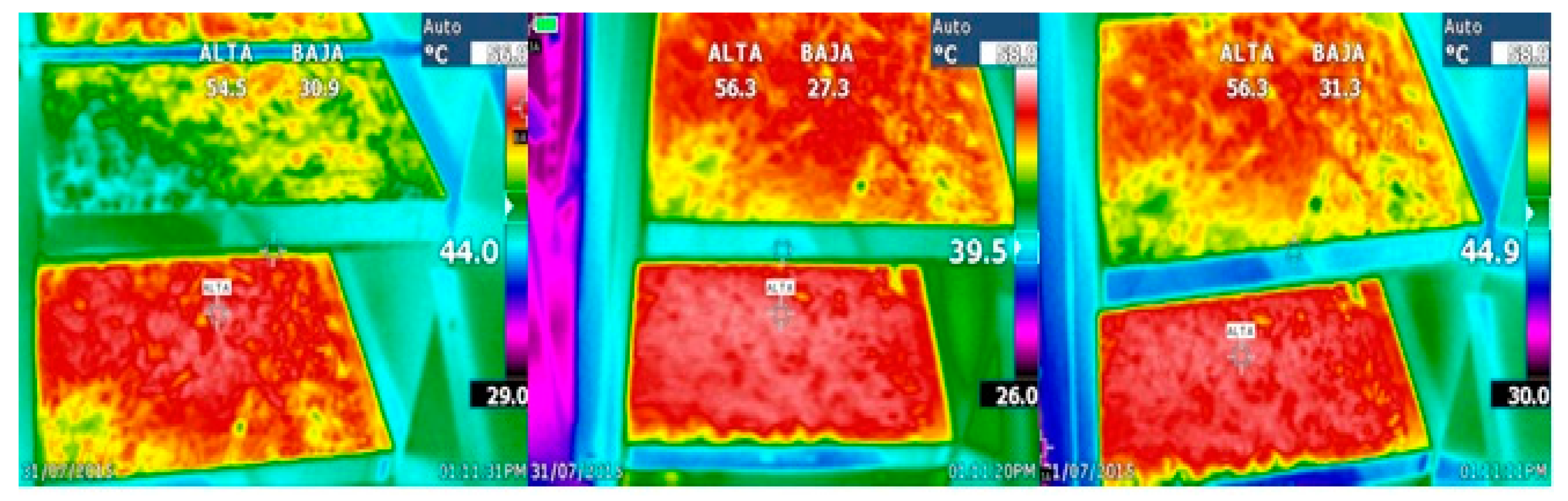
3.1. Cogeneration Performance and Heat Exchanger Performance
3.2. Drying Analyses
4. Conclusions
Author Contributions
Funding
Acknowledgments
Conflicts of Interest
References
- Rocha, M.S.; Andreos, R.; Simões-Moreira, J.R. Performance tests of two small trigeneration pilot plants. Appl. Therm. Eng. 2012, 41, 84–91. [Google Scholar] [CrossRef]
- Kosowski, K.; Tucki, K.; Piwowarski, M.; Stępień, R.; Orynycz, O.; Włodarski, W. Thermodynamic Cycle Concepts for High-Efficiency Power Plants. Part B: Prosumer and Distributed Power Industry. Sustainability 2019, 11, 2647. [Google Scholar] [CrossRef]
- Goyal, R.; Sharma, D.; Soni, S.L.; Gupta, P.K.; Johar, D. An experimental investigation of CI engine operated micro-cogeneration system for power and space cooling. Energy Convers. Manag. 2015, 89, 63–70. [Google Scholar] [CrossRef]
- Instituto de Planificación y Promoción de Soluciones Energéticas Para Las Zonas no Interconectadas (IPSE). Available online: http://www.ipse.gov.co/ipse/informacion-institucional/ipse (accessed on 25 August 2015).
- Behrentz, E.; Cadena, Á.; Delgado, R.; Espinosa, M.; Hernández, M.; Ovalle, K. Productos Analíticos Para Apoyar La Toma De Decisiones Sobre Acciones De Mitigación a Nivel Sectorial Oferta De Energía: Generación Eléctrica, Petróleo, Gas Y Carbón; Universidad de los Andes: Bogotá, Colombia, 2014. [Google Scholar]
- Frias, O. Programa de Uso Racional y Eficiente de Energia y Fuentes no Convencionales—PROURE. 2010. Available online: http://www1.upme.gov.co/DemandaEnergetica/MarcoNormatividad/plan.pdf (accessed on 6 September 2019).
- Rolón, J.E. Optimización de Un Secador de Flujo Cruzado Para Plantas Aromáticas; Universidad Nacional de Colombia: Bogotá, Colombia, 2014. [Google Scholar]
- Erdem, H.H.; Akkaya, A.V.; Dagdas, A.; Sevilgen, S.H.; Cetin, B.; Sahin, B.; Teke, I.; Gungor, C.; Atas, S.; Basak, M.Z. Renovating thermal power plant to trigeneration system for district heating/cooling: Evaluation of performance variation. Appl. Therm. Eng. 2015, 86, 35–42. [Google Scholar] [CrossRef]
- Garnett, T. Food Refrigeration: What is the Contribution to Greenhouse Gas Emissions and How Might Emissions Be Reduced; Food Climate Research Network-Centre for Environmental Strategy University of Surrey: Guildford, UK, 2007. [Google Scholar]
- Maidment, G. Sustainable Innovation—A Technology Review. In Proceedings of the 1st IIR International Conference on Sustainability and the Cold Chain, Cambridge, UK, 29–31 March 2010. [Google Scholar]
- Yingjian, L.; Qi, Q.; Xiangzhu, H.; Jiezhi, L. Energy balance and efficiency analysis for power generation in internal combustion engine sets using biogas. Sustain. Energy Technol. Assess. 2014, 6, 25–33. [Google Scholar] [CrossRef]
- Lee, D.H.; Park, J.S.; Ryu, M.R.; Park, J.H. Development of a highly efficient low-emission diesel engine-powered co-generation system and its optimization using Taguchi method. Appl. Therm. Eng. 2013, 50, 491–495. [Google Scholar] [CrossRef]
- Zhao, X.L.; Fu, L.; Zhang, S.G.; Jiang, Y.; Li, H. Performance improvement of a 70 kWe natural gas combined heat and power (CHP) system. Energy 2010, 35, 1848–1853. [Google Scholar] [CrossRef]
- Blumberg, T.; Sorgenfrei, M.; Tsatsaronis, G. Design and Assessment of an IGCC Concept with CO2 Capture for the Co-Generation of Electricity and Substitute Natural Gas. Sustainability 2015, 7, 16213–16225. [Google Scholar] [CrossRef]
- Abusoglu, A.; Kanoglu, M. First and second law analysis of diesel engine powered cogeneration systems. Energy Convers. Manag. 2008, 49, 2026–2031. [Google Scholar] [CrossRef]
- Aussant, C.D.; Fung, A.S.; Ugursal, V.I.; Taherian, H. Residential application of internal combustion engine based cogeneration in cold climate-Canada. Energy Build. 2009, 41, 1288–1298. [Google Scholar] [CrossRef]
- Lu, Y.; Wang, Y.; Dong, C.; Wang, L.; Roskilly, A.P. Design and assessment on a novel integrated system for power and refrigeration using waste heat from diesel engine. Appl. Therm. Eng. 2015, 91, 591–599. [Google Scholar] [CrossRef]
- Castro, D.; Diaz, J.; Serna, R. Cultivo y Producción de Plantas Aromáticas y Medicinales. 2013. Available online: https://conectarural.org/sitio/material/cultivo-y-producci%C3%B3n-de-plantas-arom%C3%A1ticas-y-medicinales (accessed on 6 September 2019).
- Hossain, M.B.; Barry-Ryan, C.; Martin-Diana, A.B.; Brunton, N.P. Effect of drying method on the antioxidant capacity of six Lamiaceae herbs. Food Chem. 2010, 123, 85–91. [Google Scholar] [CrossRef]
- Doymaz, I. Thin-layer drying behaviour of mint leaves. J. Food Eng. 2006, 74, 370–375. [Google Scholar] [CrossRef]
- El-Sebaii, A.A.; Shalaby, S.M. Experimental investigation of an indirect-mode forced convection solar dryer for drying thymus and mint. Energy Convers. Manag. 2013, 74, 109–116. [Google Scholar] [CrossRef]
- García-Navarrete, F.J. Evaluación De Los Efectos Del Proceso De Secado Sobre La Calidad De La Stevia (Stevia Rebaudiana Bertoni) Y La Hierbabuena (Mentha Spicata); Universidad Nacional de Colombia: Bogotá, Colombia, 2014. [Google Scholar]
- García, S.V.; Schmalko, M.E.; Tanzariello, A. Isotermas de absorción y cinética de secado de ciertas hortalizas y aromáticas cultivadas en misiones. RIA 2007, 36, 115–129. [Google Scholar]
- Kaya, A.; Aydin, O. An experimental study on drying kinetics of some herbal leaves. Energy Convers. Manag. 2009, 50, 118–124. [Google Scholar] [CrossRef]
- Śledź, M.; Nowacka, M.; Wiktor, A.; Witrowa-Rajchert, D. Selected chemical and physico-chemical properties of microwave-convective dried herbs. Food Bioprod. Process. 2013, 91, 421–428. [Google Scholar] [CrossRef]
- Ayadi, M.; Mabrouk, S.B.; Zouari, I.; Bellagi, A. Kinetic study of the convective drying of spearmint. J. Saudi Soc. Agric. Sci. 2014, 13, 1–7. [Google Scholar] [CrossRef] [Green Version]
- Sallam, Y.I.; Aly, M.H.; Nassar, A.F.; Mohamed, E.A. Solar drying of whole mint plant under natural and forced convection. J. Adv. Res. 2013, 6, 171–178. [Google Scholar] [CrossRef] [Green Version]
- Jin Park, K.; Vohnikova, Z.; Pedro Reis Brod, F. Evaluation of drying parameters and desorption isotherms of garden mint leaves (Mentha crispa L.). J. Food Eng. 2002, 51, 193–199. [Google Scholar] [CrossRef]
- Szumny, A.; Figiel, A.; Gutiérrez-Ortíz, A.; Carbonell-Barrachina, Á.A. Composition of rosemary essential oil (Rosmarinus officinalis) as affected by drying method. J. Food Eng. 2010, 97, 253–260. [Google Scholar] [CrossRef]
- Antal, T.; Kerekes, B.; Sikolya, L. influence of drying on the volatile compounds of spearmint (Mentha spicata L.). 2011. Available online: http://www.uibcongres.org/imgdb/archivo_dpo11058.pdf (accessed on 6 September 2019).
- Kamyar, a.; Ong, K.S.; Saidur, R. Effects of nanofluids on heat transfer characteristics of a two-phase closed thermosyphon. Int. J. Heat Mass Transf. 2013, 65, 610–618. [Google Scholar] [CrossRef]
- Shanbedi, M.; Heris, S.Z.; Amiri, A.; Baniadam, M. Improvement in Heat Transfer of a Two-Phased Closed Thermosyphon Using Silver-Decorated MWCNT/Water. J. Dispers. Sci. Technol. 2014, 35, 1086–1096. [Google Scholar] [CrossRef]
- Noie, S.H.; Heris, S.Z.; Kahani, M.; Nowee, S.M. Heat transfer enhancement using Al2O3/water nanofluid in a two-phase closed thermosyphon. Int. J. Heat Fluid Flow 2009, 30, 700–705. [Google Scholar] [CrossRef]
- Incropera, F.P.; DeWitt, D.P.; Bergman, T.L.; Lavine, A.S. Fundamentals of Heat and Mass Transfer, 6th ed.; John Wiley & Sons: Chichester, UK, 2006. [Google Scholar]
- Žukauskas, A. Heat Transfer from Tubes in Crossflow. Adv. Heat Transf. 1972, 8, 93–160. [Google Scholar]
- Danielewicz, J.; Sayegh, M.A.; Śniechowska, B.; Szulgowska-Zgrzywa, M.; Jouhara, H. Experimental and analytical performance investigation of air to air two phase closed thermosyphon based heat exchangers. Energy 2014, 77, 82–87. [Google Scholar] [CrossRef] [Green Version]
- Mroue, H.; Ramos, J.B.; Wrobel, L.C.; Jouhara, H. Experimental and numerical investigation of an air-to-water heat pipe-based heat exchanger. Appl. Therm. Eng. 2015, 78, 339–350. [Google Scholar] [CrossRef] [Green Version]
- Gulcimen, F.; Karakaya, H.; Durmus, A. Drying of sweet basil with solar air collectors. Renew. Energy 2016, 93, 77–86. [Google Scholar] [CrossRef]
- Sapra, H.; Godjevac, M.; Visser, K.; Stapersma, D.; Dijkstra, C. Experimental and simulation-based investigations of marine diesel engine performance against static back pressure. Appl. Energy 2017, 204, 78–92. [Google Scholar] [CrossRef]
- Sivaram, A.R.; Rajavel, R.; Jayakumar, N.; Vinothkumar, M. Exhaust back pressure effect on the performance features of a diesel engine. Arpn J. Eng. Appl. Sci. 2017, 12, 5353–5356. [Google Scholar]
- He, W.; Wang, S. Thermoelectric performance optimization when considering engine power loss caused by back pressure applied to engine exhaust waste heat recovery. Energy 2017, 133, 584–592. [Google Scholar] [CrossRef]
- Burnete, N.; Moldovanu, D.; Baldean, D.L.; Kocsis, L. Studies Regarding the Influence of Exhaus Backpressure on the Performances of a Compression Ignited Engine. In Proceedings of the European Automotive Congress EAEC-ESFA 2015, Bucharest, Romania, 25–27 November 2015; Andreescu, C., Clenci, A., Eds.; Springer: Berlin/Heidelberg, Germany, 2015; pp. 141–149. [Google Scholar]
- Jouhara, H.; Meskimmon, R. Experimental investigation of wraparound loop heat pipe heat exchanger used in energy efficient air handling units. Energy 2010, 35, 4592–4599. [Google Scholar] [CrossRef]
- Jouhara, H.; Merchant, H. Experimental investigation of a thermosyphon based heat exchanger used in energy efficient air handling units. Energy 2012, 39, 82–89. [Google Scholar] [CrossRef]
- Noie, S.H. Investigation of thermal performance of an air-to-air thermosyphon heat exchanger using ε-NTU method. Appl. Therm. Eng. 2006, 26, 559–567. [Google Scholar] [CrossRef]
- Tonguino Borja, M.I. Determinación De Las Condiciones Óptimas Para La Deshidratación De Dos Plantas Aromáticas; Universidad Tècnica del Norte: Ibarra, Ecuador, 2011. [Google Scholar]


| Equipment | Characteristics | Specifications |
|---|---|---|
| Generator set | Compression ignition engine | YANMAR 3TNE84, DI, four stroke, three cylinders, naturally aspirated, water cooled, Diesel fuel Rated power: 14.8 KW |
| Generator | MECC ALTE—ECO28 3L/2 31 kVA (24.8 kW) 1800 RPM | |
| Drying system | Heat exchanger | Counter-flow air-exhaust gases, with fifty copper thermosyphons filled with water. Dimensions W × D × H: 0.26 × 0.76 × 0.54 m |
| Air blower | Centrifugal fan, 0.36 kW, 2100 RPM | |
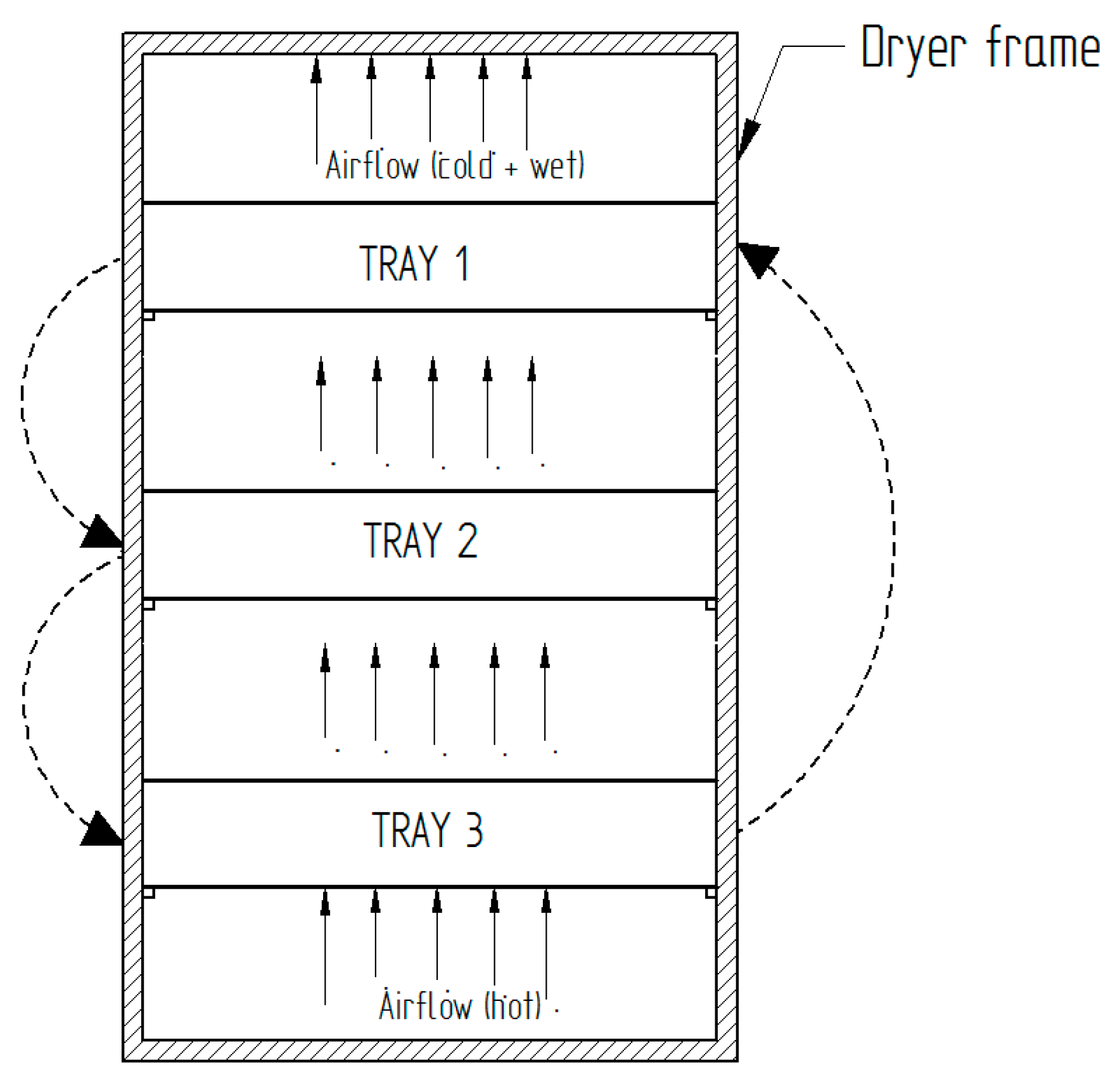
| Dryer | Convective three trays, Drying Chamber dimensions W * D * H: 0.51 * 0.51 * 1.05 m |
| AH | Initial Moisture (%) | Tray Load 1 (Kg) | Tray Load 2 (Kg) | Tray Load 3 (Kg) |
|---|---|---|---|---|
| Origanum vulgare | 84 | 0.27 | 0.27 | 0.27 |
| Mentha spicata | 78 | 0.42 | 0.42 | 0.42 |
| Ocimum basilicum | 87.3 | 0.22 | 0.22 | 0.22 |
| Variable | Associated Uncertainty |
|---|---|
| Thermocouples | ±0.3 °C |
| Coriolis mass flow rate | ±8.7 × 10⁻⁵ kg/s |
| Pitot tube meter | ±12.7 × 10⁻⁴ m3/s |
| Generator efficiency | 88% at full load |
| Efficiency | ±0.9% |
| Recovered heat | ±0.6% |
| Effectiveness | ±0.8% |
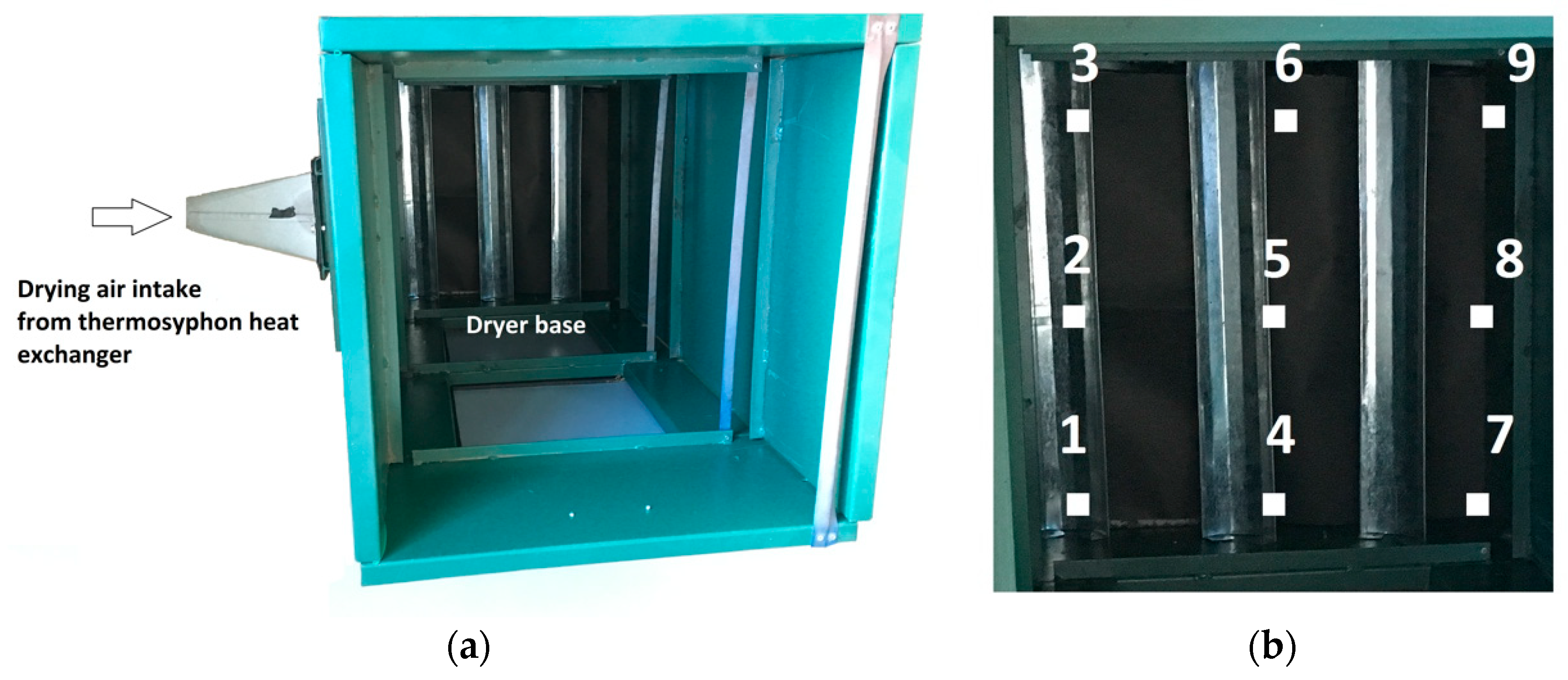
| Measuring Point | Drying Air Velocity (m/s) | Measuring Point | Drying Air Velocity (m/s) | Measuring Point | Drying Air Velocity (m/s) |
|---|---|---|---|---|---|
| 1 | 0.35 | 4 | 0.15 | 7 | 0.1 |
| 2 | 0.45 | 5 | 0.25 | 8 | 0.2 |
| 3 | 0.3 | 6 | 0.15 | 9 | 0.1 |
© 2019 by the authors. Licensee MDPI, Basel, Switzerland. This article is an open access article distributed under the terms and conditions of the Creative Commons Attribution (CC BY) license (http://creativecommons.org/licenses/by/4.0/).
Share and Cite
Olmos-Villalba, L.; Herrera, B.; Gallego, A.; Cacua, K. Experimental Evaluation of a Diesel Cogeneration System for Producing Power and Drying Aromatic Herbs. Sustainability 2019, 11, 5121. https://0-doi-org.brum.beds.ac.uk/10.3390/su11185121
Olmos-Villalba L, Herrera B, Gallego A, Cacua K. Experimental Evaluation of a Diesel Cogeneration System for Producing Power and Drying Aromatic Herbs. Sustainability. 2019; 11(18):5121. https://0-doi-org.brum.beds.ac.uk/10.3390/su11185121
Chicago/Turabian StyleOlmos-Villalba, Luis, Bernardo Herrera, Anderson Gallego, and Karen Cacua. 2019. "Experimental Evaluation of a Diesel Cogeneration System for Producing Power and Drying Aromatic Herbs" Sustainability 11, no. 18: 5121. https://0-doi-org.brum.beds.ac.uk/10.3390/su11185121