1. Introduction
Drawing is an element essential to attain the preservation and sustainability of architectural heritage. In the restoration and preservation of any historic building, it is crucial to rely on updated, accurate graphic documentation [
1]. A monument that is accurately documented will have a greater chance to survive across time, even after adverse and disastrous events. Even when fatal destruction happens, the building’s intangible value remain safe thanks to graphic documentation, as these documents will eventually facilitate virtual or real reconstruction of the monument.
Muqarnas are one of the most admired elements in the 14th century Nasrid architecture found in the Alhambra. Despite their frailty, the muqarnas produce complex arrays of amazing visual effects. Muqarnas exist in very different architectonic elements like friezes, capitals, complex domes, arcs, and pendentives, and their abundant variety of shapes was developed under the reign of Muhammad V [
2,
3,
4]. Even today, little is known of the muqarnas complex process of 3-D geometrical construction, starting from very simple pieces, since only simple shapes were available.
For all these reasons, the main goal of this research is to provide a new and accurate graphic documentation concerning some of these fragile architectonic elements in order to facilitate a better understanding and sustainability of the muqarnas. This work has used, for the first time, 21st century graphical techniques for their representation, specifically a 3-D laser scanner. It should be highlighted that nowadays there are no digital drawings representing the muqarnas complex shapes existing in the Alhambra Nasrid Palaces. Moreover, only a few authors have depicted the muqarnas using traditional drawings, and only a few examples are included in 19th century plans, just as the ones by Jones and Goury commented here.
Different muqarnas groups in the monumental complex could be scanned thanks to the precious collaboration of the Council Patronato de la Alhambra y Generalife and the pendentives from the Sala de la Barca located in the Comares palace were finally selected for this paper. This hall is a prominent rectangular room used as a precedent space to the Salón de Embajadores (throne room) and supports a splendid lattice dome.
In our study, the 3-D muqarnas construction comprises a difficult geometric solution because the muqarnas elevate from two allegedly orthogonal plans up to the arc of the circle supporting the upper dome. There are remarkable graphic references documenting this case: the drawings published in 1842–1845 by architects Owen Jones and Jules Goury, along with a text explaining the principles for grouping geometrically the muqarnas.
Among the bibliographical references on the muqarnas, two manuscripts on carpentry from 17th century should be mentioned: the ones by Fray Andrés de San Miguel [
5] and Diego López de Arenas [
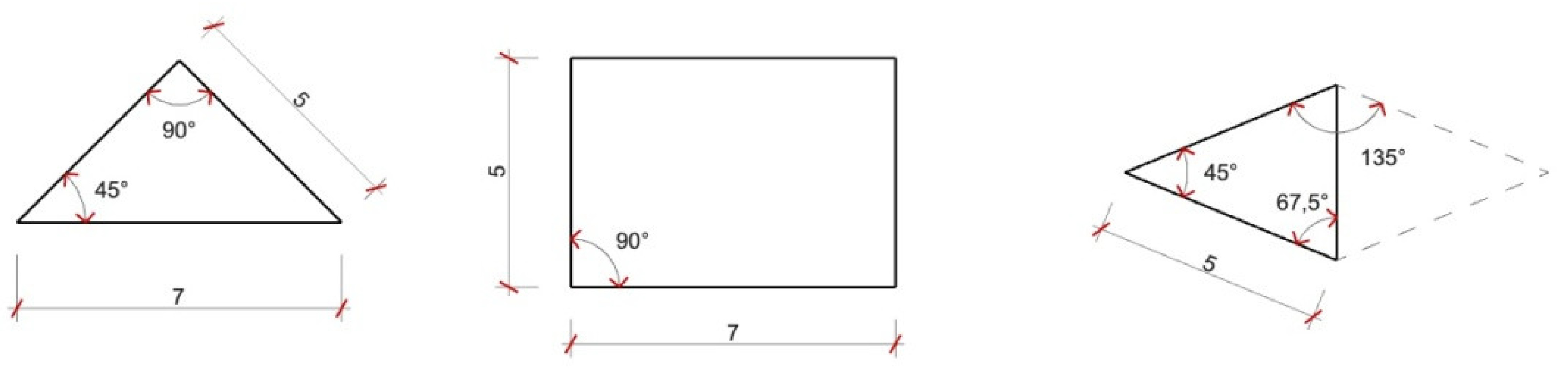
6]. These authors explain how to geometrically build the plan from three geometrically flat shapes (
Figure 1); a rectangle with ratio 5 to 7 (rounded to 5 root of 2), an isosceles right triangle composed of two cathetus of 5, and a hypotenuse of 7 (also rounded) and an isosceles triangle with 45° angle and longer sides of 5, making possible to combine the last one with an identical symmetrical triangle pivoting on the shortest side. Theoretically, the layout of the muqarnas’ inner angles are reduced to four: 45°, 67.5°, 90°, and 135°. Taking into account that muqarnas follow the patterns produced by those angles, it is possible to identify whether if they are deformed with respect to their original shape.
Along with the above-mentioned historical studies about muqarnas, it should be highlighted the research works from the architect Enrique Nuere (late 20th century), who graphically analyzed muqarnas’ component pieces [
7]. Nuere´s work was the precursor for new studies based on CAD drawings [
8,
9,
10] concerning the theoretical geometric grouping of pieces. Some of those studies refer to wooden muqarnas but other do not indicate the construction material and only focus on their complex geometry; all of those studies took into account the deformations we have detected in the plaster muqarnas of the Alhambra after analyzing the scanner 3-D data in our research.
Considering the vast bibliography about the Alhambra architecture and its graphic representations [
11] it should be pointed out that the early plans from the Sala de la Barca date from 1766, when several surveys of the monument were performed and then published in 1787 by the Real Academia de Bellas Artes de San Fernando in Madrid [
12], and later, in 1837, the French architect Philibert Girault de Prangey reproduced those surveys in his book about the Alhambra [
13]. Both publications included a plan and a cross section from the Comares palace, where it is shown that the ceiling from the Sala de la Barca was modified in the late half of the 19th century.
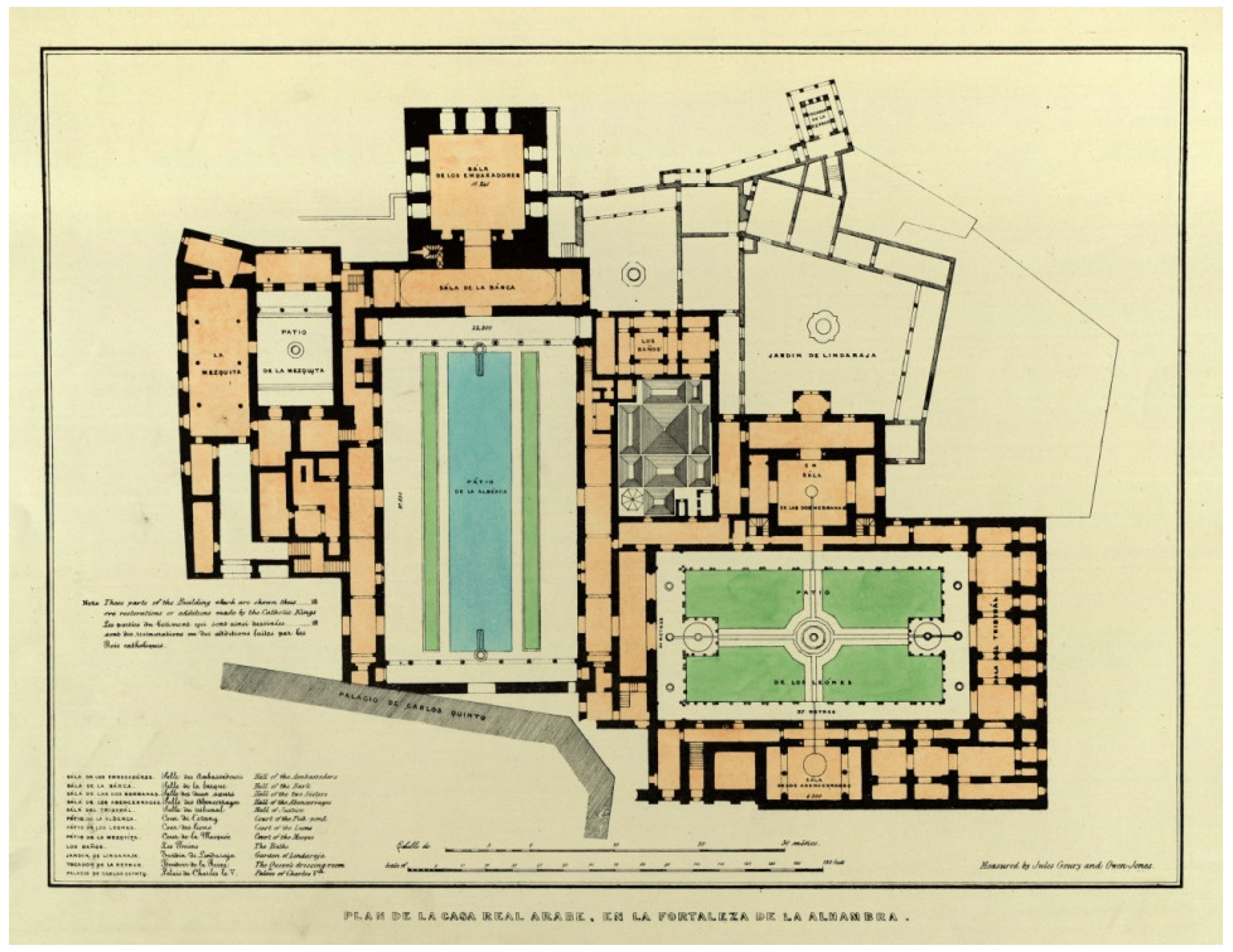
The drawings of the Alhambra by architects Owen Jones and Jules Goury [
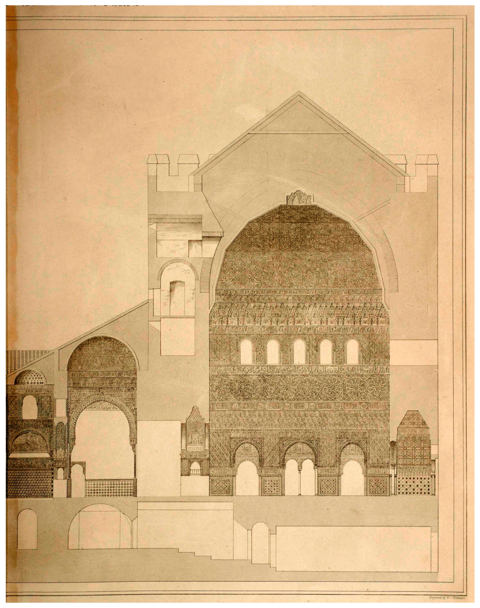
14] date from 1834 and 1837 and focus on the elements’ ornamentation, which are even more interesting and significant than the ones previously mentioned because their decorative aspect. Jones and Goury did not represent the horizontal deformations and misalignments existing in the Nasrid palaces when they drew the distribution plan (
Figure 2); they neatly represent in detail the Sala de la Barca setting when they draw the longitudinal cross section from the Comares palace (
Figure 3) [
14].
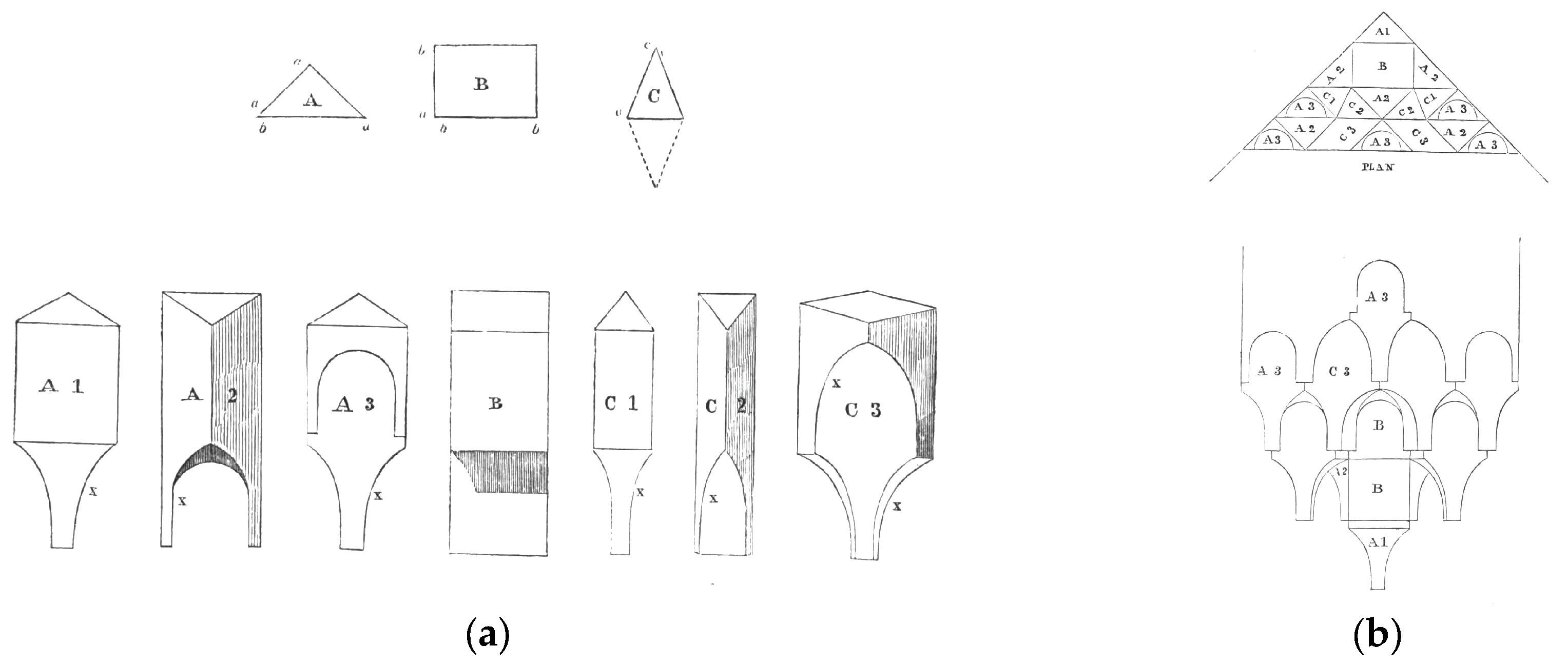
Plate X in volume I published in Goury et al. [
14] includes a pendentive schematic diagram and elevation from the Sala de la Barca (
Figure 4). Jones and Goury should have been aware of the complexity of their muqarnas drawings, and for this reason they attached an explanatory text about the theoretical grouping process of elemental pieces (in a simplified version). The explanatory text is the following:
“These pendentives are of a very curious mathematical construction. They are composed of numerous prisms of plaster, united by their contiguous lateral surfaces, consisting of seven different forms, proceeding from three primary figures on plan: they are, the right angle triangle (A), the rectangle (B), and the isosceles triangle (C). In these (a a, a b, a c) are equal; (b a) is equal to (b b), and the vertical angle of the isosceles triangle (C) is 45°. The figure (B) has one form, in section; the figure (A) three; and figure (C) three; the third (C3) being a rhomboid, formed by the double isosceles triangle. The curves (x x x) of the several pieces are similar, by which it will be seen that a piece may be combined with any one of the others by either of its sides; thus rendering them susceptible of combinations as various as the melodies which may be produced from the seven notes of the musical scale.”
Together with the previous text, Jones and Goury provided both a schematic diagram and elevation drawings from the three basic shapes (triangles and rectangles), the seven muqarnas pieces, and primary combinations among them (
Figure 5).
In 1837, the Pisani brothers made some plaster molds from the Patio de los Leones [
15], and followed that formula or “recipe.” Rafael Contreras (Alhambra curator and decorator) built and replaced a lot of ornaments using plaster since half 19th century.
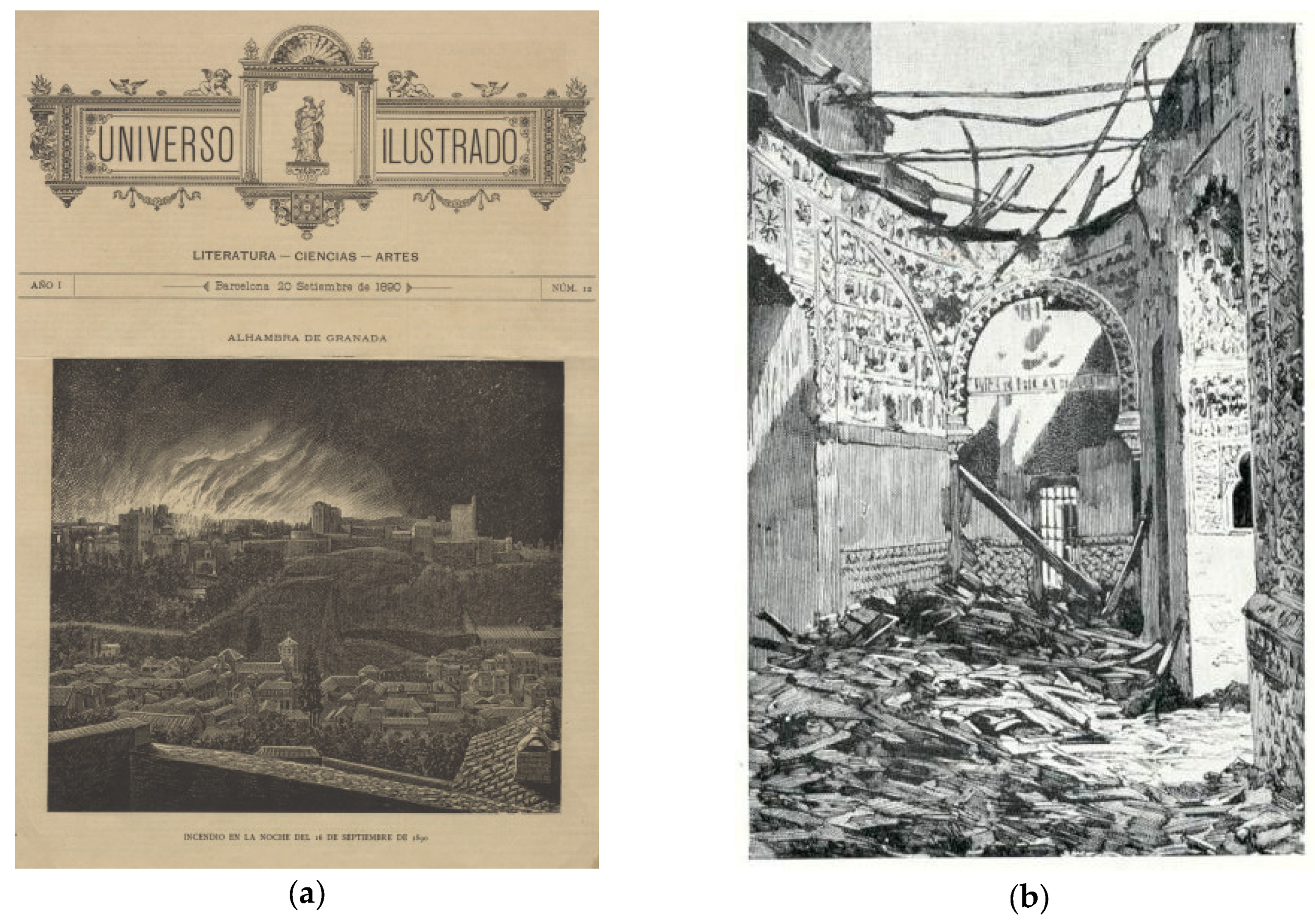
It must be taken into account that on September 16, 1890, the Sala de la Barca was damaged by an aggressive fire that destroyed the dome, according the press of that time (
Figure 6a) [
16]. Nevertheless, the photos and drawings of the fire event showed that the pendentives did not suffer significant damage (
Figure 6b). The reconstruction of the current wood dome was accomplished by the team led by José Romera, circa 1960 [
17].
2. Materials and Methods. Data Capture and Analysis
The unpublished graphic representations from the Sala de la Barca displayed in this paper have originated starting from the data captured by a BLK360 laser scanner (Leica, Heerbrugg, Switzerland), with an accuracy of 6 mm at a 10-m distance and 8 mm at 20 m. The complete point cloud was levelled using a total station Leica TS02 (Leica, Heerbrugg, Switzerland) with 3’’ angular accuracy and 1.5 mm ± 2 ppm distance accuracy. The scanning process focused on the muqarnas area, although in every scan, station data of the complete 360° volume were also registered. For this reason, every scan displays floors, walls, decorations, pillars, columns, and doors. Simultaneously, to every scan we took HDR (high definition resolution) pictures with the scanner cameras [
18].
The scanner can be set to several densities for the point cloud: low, mean, and high, corresponding to point resolutions of 20 mm, 10 mm, and 5 mm, respectively, considering a plane perpendicular to the laser beam at a distance of 10 m. This study used average quality in all scans.
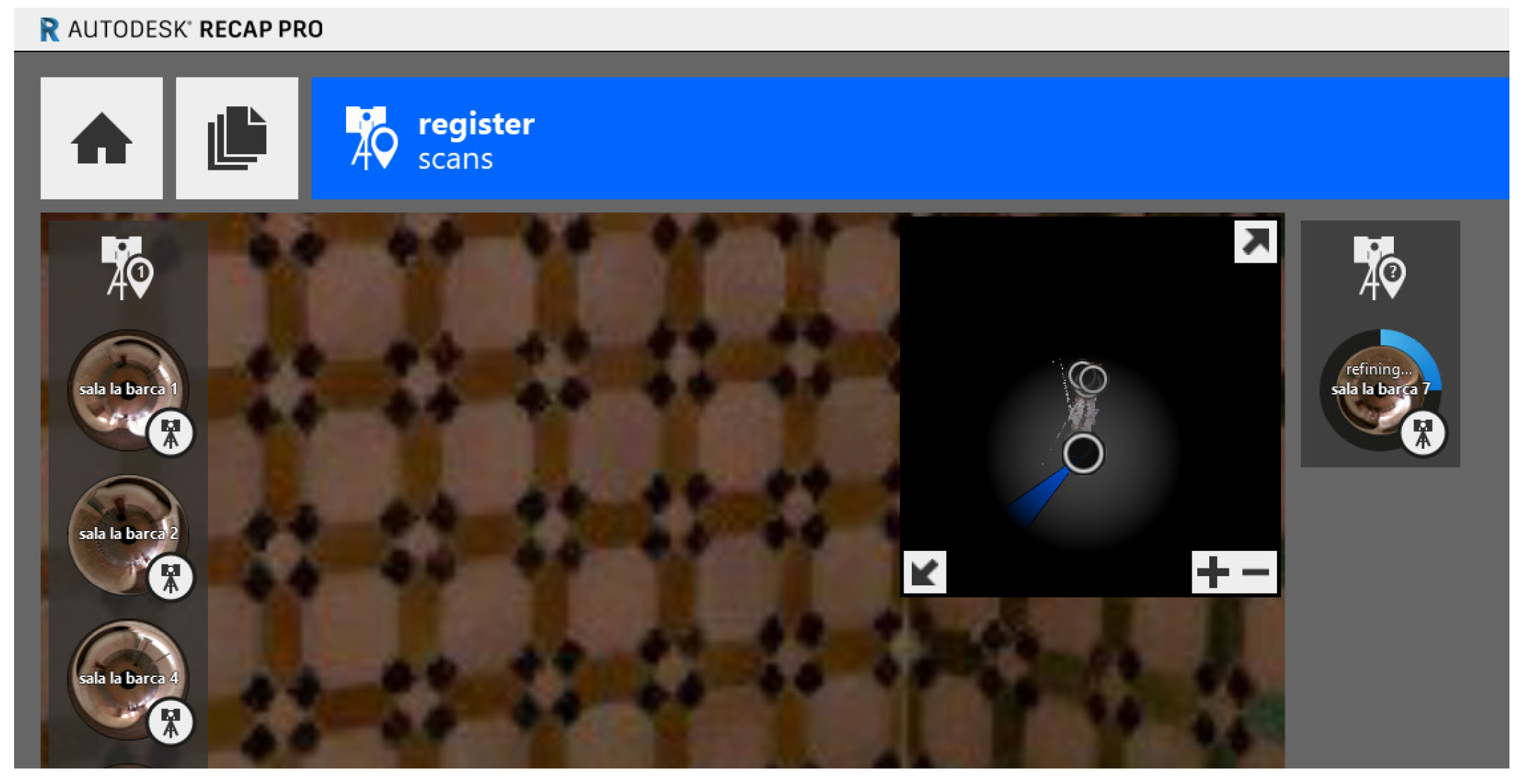
The registration process consisted of referencing all the point clouds to the same reference system, such that homologous points (those points that belonging to different point clouds represent the same point) match each other; for this task Recap Pro 4.0 (Autodesk, San Rafael, USA) was used. There exists a Recap version for running on an iPad, such that the registration was performed automatically when some constraints were satisfied, or manually in other cases (scarce overlapping, noise caused by distorting elements, e.g., tourists walking around the scanned area). In the study, most of the scans were manually registered because most of them showed images of tourists. Another reason for manually registration was the limited time we had for accessing the Alhambra, so that the priority was to take as many scans as possible.
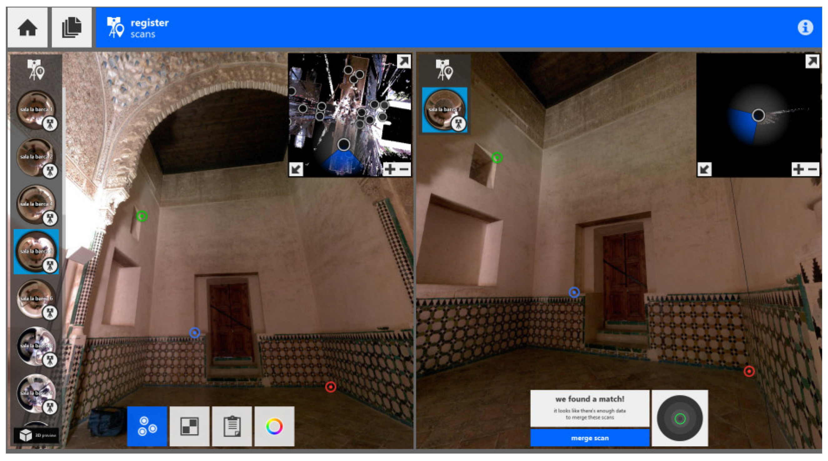
Figure 7 shows an example of point cloud registration: the left image shows the scans already registered, and the right shows a scan about to be registered (StR). The image on the left corresponds to the reference scan (RS). The panoramic images of RS and StR had common areas where we could identify homologous points. Three homologous points were selected (each homologous point had the same color in RS and StR) and Recap computed the transformation matrix of an approximated StR register using those three homologous points. The software provided a graphic indicator about the quality achieved by the approximated registration process: the right image in
Figure 7 shows a grayscale circle with an inner circumference; the circumference color can be green, yellow, or red indicating that the approximated registration was good, suitable, or bad, respectively. If we accept the approximated registration Recap proceeded to refine the adjustment using an iterative closest point (ICP) algorithm: some examples from ICP can be found in Sharp et al. [
19] and Pormelau et al. [
20].
Figure 8 shows the instant of ICP refinement of Recap after accepting the approximated registration (right upper corner).
Three indices described the registration quality as a percentage. The indices are the following: (1) overlapping indicates the area percentage of StR shared by the RS; (2) balance is a measure that encodes the relative amount of the data in three orthonormal directions, indicating how much StR registration has been constrained in the three orthogonal directions; and (3) error <6 mm indicates the points percentage in the StR that match the SF separated less than 6 mm.
Table 1 shows the three indices values for the six scan stations used in the study of the muqarnas pendentives in the Sala de la Barca.
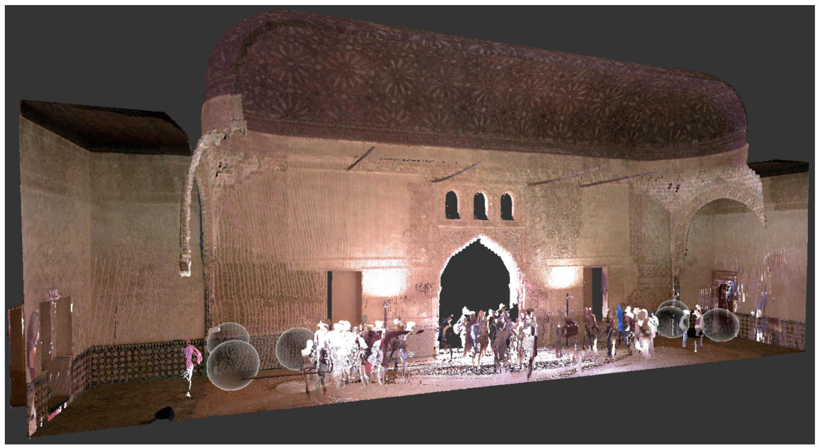
The scan stations used in the Sala de la Barca surveys are shown in
Figure 9, where they are represented using grey spheres; the image is a cross section perspective view from the point cloud.
After registering all the scan stations, the complete point cloud was levelled. A total station Leica TS02 was used for this task, measuring six sharp points placed on the tiles of the Sala de la Barca. Then, the registered scan stations were exported in Recap as a unique point cloud; this point cloud was levelled using the CloudCompare 2.10 (
http://cloudcompare.org) software and the six mentioned points. We obtained an RMSE (root mean square error) of 1.1 cm after performing a least squares fitting.
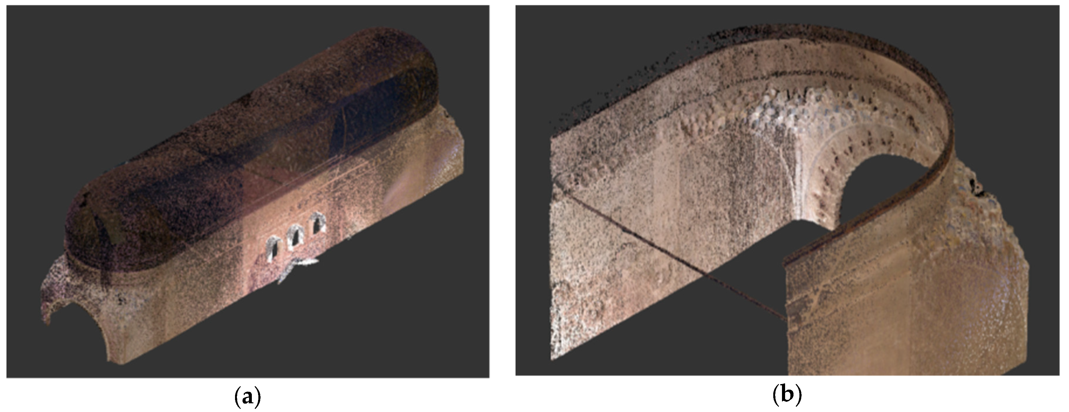
Data analysis comprised several phases: (1) interest areas were selected and extracted using Recap software (
Figure 10); (2) plans, elevations, and sections were derived from the point cloud using CloudCompare software; and (3) key points were identified on plans projections and simplified drawings have been delineated based on them, where the bounds of muqarnas groups and the main inner axis have been detected. The starting and ending that defined different levels have been located over sections and elevations, and when necessary, we drew the vertical in order to measure distances and angles.
Later, we compared the above-mentioned information with the theoretical geometric model. We used the bound for dimensioning the set and we based them on photographs for drawing a schematic plan for the muqarnas set in order to check their geometry, hypothetical inconsistences, and axis and angles deformations. Finally, the plan geometry, including distances and angles to confirm the detected deformations, was analyzed.
3. Results: Muqarnas Pendentives Deformations
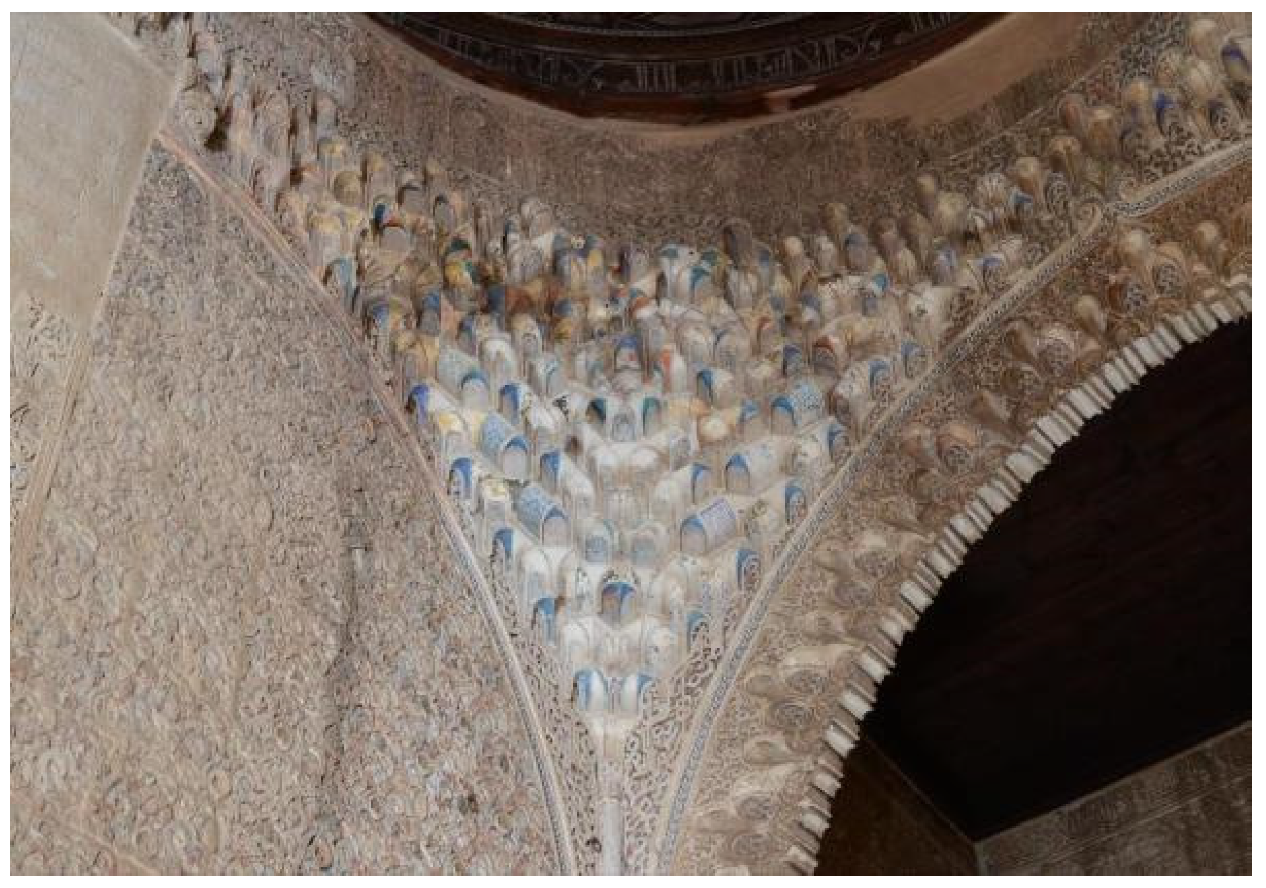
From our own photographs (
Figure 11) we observed some differences between northern and eastern pendentives in the Sala de la Barca, although they are symmetric considering their typology.
The drawing from Jones and Goury matches the north-eastern side, closer to the Comares Room; this drawing shows that plan and elevation geometrically match each other and also the matching occurs between the draw pieces and the real ones.
Nevertheless, we have detected discrepancies between the Jones and Goury text and their plan drawing. According the muqarnas grouping rules, defined by the mentioned architects, every piece should have the same module, nevertheless their drawing shows the inner pieces are smaller that the outer ones; the pieces deformations increase when they are closer to the upper bound circumference and the triangles become all unequal and stretched.
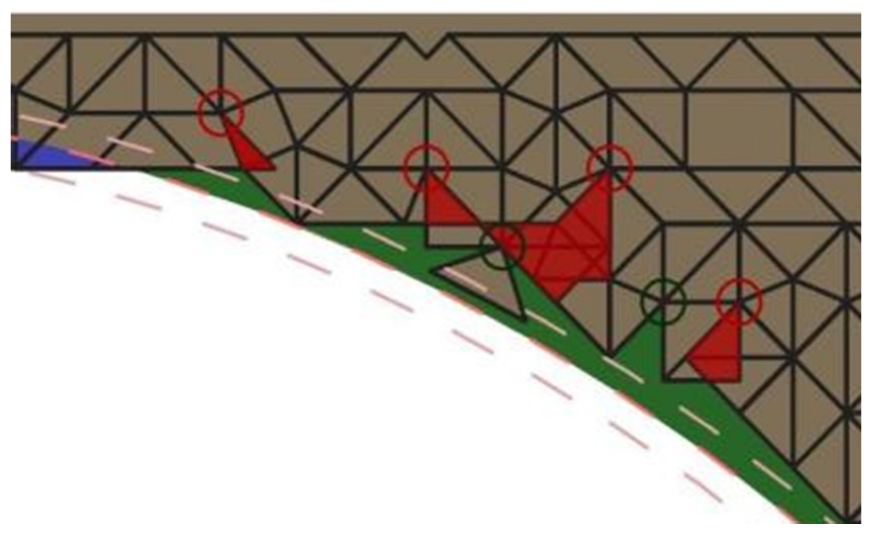
Comparing the above-mentioned drawing inconsistencies with current photos we observed that the drawing was not wrong, i.e., the drawing deformations seem to match to the real ones. After analyzing the Jones’s drawings, we established a starting hypothesis in order to interpret our own drawings: the muqarnas were deformed from their conception to their construction. To verify our hypothesis, we identified the muqarnas pieces in both the photos and the point cloud, and we tried to draw the ideal plan following the geometric grouping rules (
Figure 12) without the real deformations existing in the room. We observe that fitting the pieces is an impossible task: in some points there are coincident pieces with both overlapping and hole angles as shown in
Figure 12 and
Figure 13 marked with red and green circles, respectively; this means that it is necessary to deform such pieces to avoid both the overlapping and holes, shaded by red and green areas, respectively, in
Figure 12 and
Figure 13.
It was proved that it is impossible build the upper levels because there was no room, and considering the horizontal dimension, the pieces would overlap. The pendentive seemed to keep strict geometric rules; nevertheless, the Nasrid constructors designed deformed pieces to match with the arch supporting the wood frame. The constructors even included filling volumes, which were difficult to see.
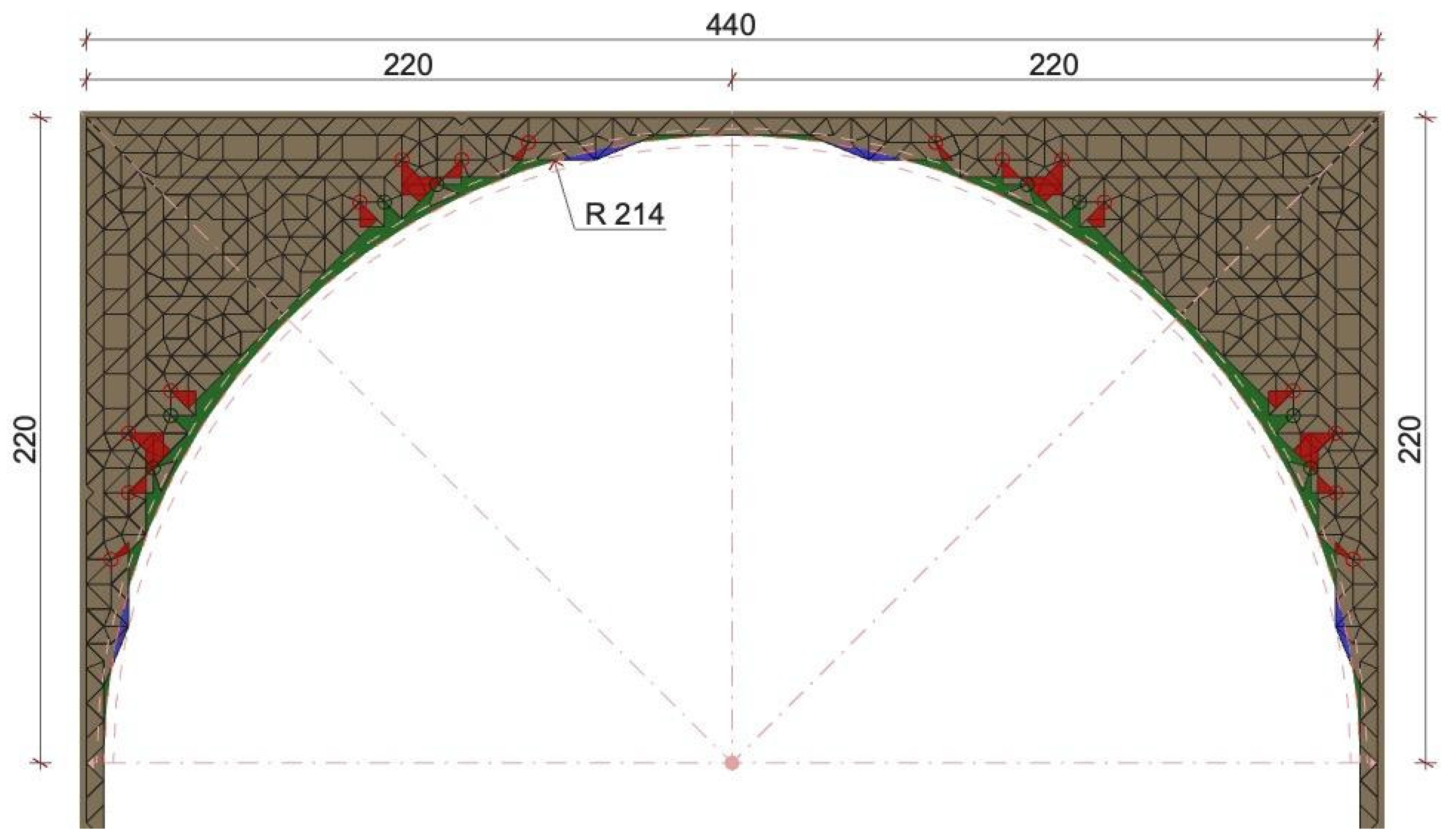
The transition circumference between the pendentive and the dome arc requires a detailed study. There are three ways to trace the arc: (1) an outer arc with radius up to the bisectors intersection from the corners to the inner of muqarnas and that cross the manifold adarajas (this solution deforms the muqarnas); (2) an inner arc touching four points in the muqarnas set that would consequently stretch the muqarnas; and (3) an intermediate arc with a 2.14 m radius shown in
Figure 13 where we can see irregular areas: in the blue areas the muqarnas should be compressed to match the arc, and in the green areas, the muqarnas should be stretched to fill the holes and achieve the arc.
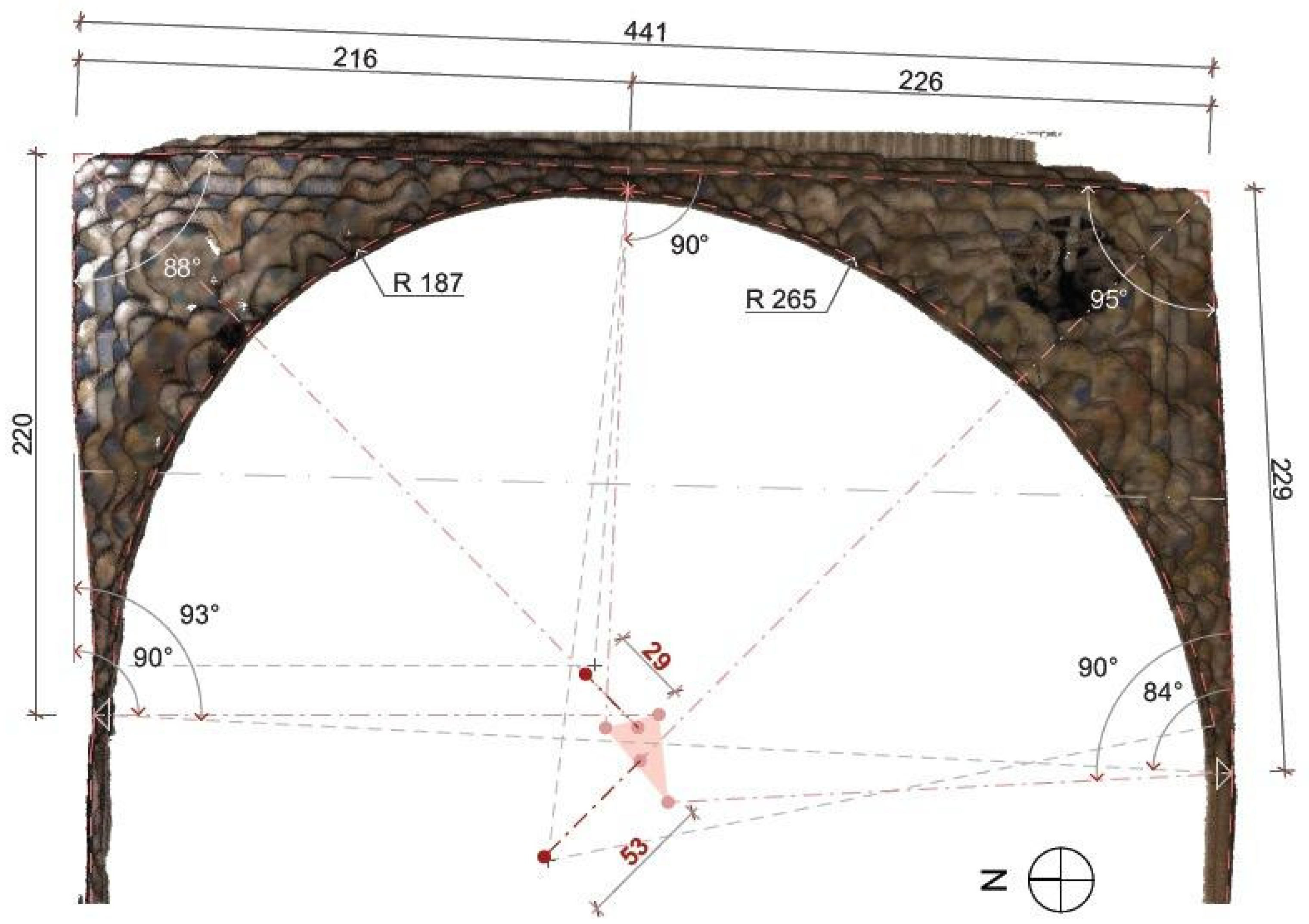
From this drawing, derived from the laser scanner (
Figure 14), it was observed that the angle between northern and eastern façades was 88°, almost orthogonal; while the angle between the southern and eastern facades was 95°.
We also detected that the upper arc, where the pendentives end up, was not a sole arc. The point where both pendentives assemble was not in the hall center; it was located 216 cm from the northern wall and 226 cm from the eastern one (
Figure 14); for this reason both pendentives were inscribed inside arcs with different radius: the southern pendentive had a 265 cm radius and its center was displaced 53 cm from the ideal place; and the norther pendentive had a 187 cm radius and its center was displaced 29 cm.
The explanations given in the previous paragraphs confirm that the NE pendentive drawn by Jones and Goury was designed with deformation and the northern pendentive muqarnas were different from the southern one. The plan in
Figure 14 shows the northern pendentive compressed inside an 88° angle with side dimensions of 220 and 216 cm; the southern pendentive was stretched inside a 95° angle with side dimensions of 226 and 229 cm. Both pendentives were different because their contour angles and dimensions and consequently their deformations were also different.
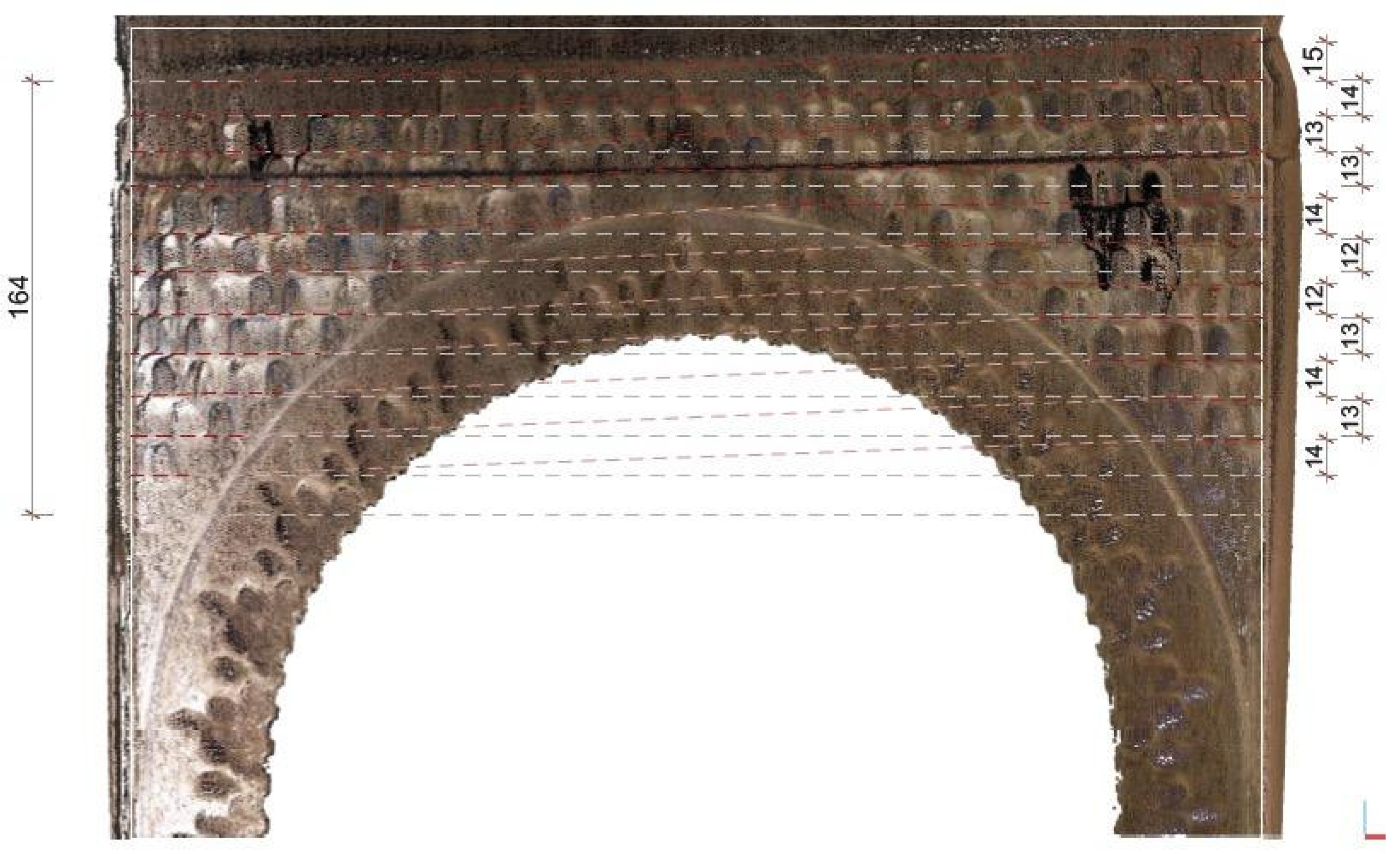
Finally, a cross-section of the hall showing certain deformations was elaborated.
Figure 15 shows marks of the starting points for each muqarnas level with a line connecting their lower parts. Thus, horizontal lines were used as references for measuring the heights. The pendentives were composed of 11 levels, each level was close to 15 cm height, and the total pendentive height was 164 cm in the northern side. Comparing the reference lines and real construction, we observe that the vertical displacement ranged from 13 to 15 cm. A hypothetical explanation is the subsidence of the northern wall that was closer to the extremely overweight Comares tower (
Figure 3) while the southern wall supports the frame weight.
4. Discussion
It is very complex to explain why the muqarnas sets in the Alhambra were deformed according to the Jones and Goury drawings, as well as the ones produced in this study. It must be taken into account that the plaster pieces from the 16th century suffered a lot of interventions: fixing, consolidation, or restoration that were not technically documented.
A suitable explanation could be that muqarnas were designed intentionally with deformations before their construction. The Nasrid craftsmen who built the Sala de la Barca pendentives had to adapt the muqarnas geometry to the circumference arc supporting the upper dome. The craftsmen would have probably deformed the muqarnas pieces as harmoniously as possible in order to solve this problem.
Deformations could also be motivated by constructive horizontal displacement. Along the centuries the Alhambra suffered fires, explosions, earthquakes, or degradations because of maintenance deficiencies [
21]. These events caused slight displacements in the walls supporting the pendentives. The consequence was that some fissures, breaks, and loss of parts took place because the plaster is a fragile material [
22]. Those interventions would use plaster filling to strengthen the muqarnas consolidating their distortions.
The vertical deformations could be caused by differential ground subsidence because the different weights supported by the walls; the consequence would be the different heights observed in muqarnas from the same level.
5. Conclusions
The current research provides new drawings based on advanced graphics techniques from the 21st century that, for the first time, document the muqarnas complex shapes from the 14th century in the Alhambra of Granada. It does not seem necessary to insist on their importance for the suitable conservation of these remarkable medieval Islamic palaces that overcame the centuries despite their fragile construction.
We selected a significant model from the Nasrid architecture, the muqarnas pendentives in the Sala de la Barca in the Comares palace, close to the Salón de Embajadores. Those pendentives have a remarkable historic documentation we evaluate: the drawings by the architects Jones and Goury and published in 1842–1845, who explained the process for their geometrical composition.
We used a laser scanner to capture the muqarnas (
Figure 16) and derived our drawings: accurate plans and elevations that unveiled significant deformations and differences between the real construction and the theoretical schemes of geometrical grouping of muqarnas defined by Jones and Goury and the rest of scientific bibliography. Our study is the first one that unveil those deformations.
Figure 12 and
Figure 13 reveal that it is impossible to build the pendentives using the method described by Jones and Goury. Both architects’ drawings contradict some pieces (
Figure 4) that do not match either their theoretical definition, nor the reality captured by the 3-D laser scanner.
Figure 14 shows that the pendentives in the Sala de la Barca are supported by walls that were not orthogonal, such that the northeastern construction was different to the southeastern one. That un-orthogonality would force the Nasrid craftsmen made designs that did not match the usual geometric process described in the muqarnas bibliography. The most uncertain and deformed area of the pendentive was found in the upper part caused when the craftsmen tried to adapt the muqarnas pieces to the circumference supporting the dome.
Figure 15 shows that the muqarnas levels were not horizontal and those in northern facade were the lowest, being a possible cause for the ground subsidence because this wall supported the Comares’ tower weight for centuries.
It should be taken into account that the Alhambra complex has suffered big earthquakes and fires, and the resultant muqarnas restorations or reconstructions would be limited to fill the plaster fissures with the same material that would consolidate the produced deformations. Despite those disasters it is amazing that muqarnas construction, made of such a fragile material, has provided their sustainable conservation along the centuries.
Finally, it is part of the goal of this paper that the accurate images created along this research are useful documentation to provide a reliable account and testimony of the complex shapes of muqarnas and their deformations, unknown until now. Our images can be very useful not only for other researchers but also for an increasing tourism that demands more knowledge about the monument. In this respect, it should be highlighted that the Alhambra in Granada is nowadays part of the World Heritage, and it is visited by around two and a half million tourists every year.


