Thermal Behavior and Measures to Prevent Condensation of a Newly Developed External Wall Panel

SH Urban Research Center, Seoul Housing & Communities Corporation, Seoul 06336, Korea
*
Author to whom correspondence should be addressed.
Sustainability 2019, 11(3), 912; https://0-doi-org.brum.beds.ac.uk/10.3390/su11030912
Submission received: 31 December 2018
/
Revised: 2 February 2019
/
Accepted: 4 February 2019
/
Published: 11 February 2019
(This article belongs to the Special Issue Sustainable Habitat)
Abstract
:An external wall panel (EWP) as a novel alternative to provide spatial flexibility and improve the performance of external walls was developed. The purpose of this study was to analyze the thermal performance of this EWP. A simulation analysis was carried out to scrutinize whether it was vulnerable to condensation, considering South Korea’s weather conditions, and find countermeasures to prevent this. Results indicated that the indoor surface temperature with the measures of added insulation materials and an inserted thermal-breaker was over 16.5 °C and that these methods could prevent condensation. In addition, this study assessed unsteady-state thermal characteristics, linear thermal transmittance, and the effective thermal transmittance of EWP. Effective thermal transmittance was estimated in consideration of the heat transmittance of EWP and the linear thermal transmittance of its slabs and its connection parts. The thermal characteristics of the building envelope are needed to analyze effective thermal transmittance and linear thermal transmittance-associated thermal bridges.
1. Introduction
According to statistical data in 2017, South Korea had 17.12 million housing units, and 10.37 million (approximately 61%) of them were apartment units [1]. Due to the mass supply of apartment complexes in a relatively short period of time, only a limited number of fixed and standardized planar designs have been used in South Korea [2]. Because 95% of these apartments have a bearing wall system, residents are not allowed to change their residential space. Thus, they cannot experience spatial diversity. In reality, there is a limit to accommodating the diverse lifestyles and needs of residents. In addition, it is not easy to maintain and repair facilities. Apartments built 30 years ago or less are being demolished for rebuilding due to the degradation of facilities and external walls. Bearing wall systems rather than column-beam systems are often used to construct apartments due to their economic advantages with respect to materials and construction [3,4,5,6], although column-beam systems are also considered for spatial flexibility. In recent years, South Korea has witnessed an increase in apartments built with column-beam systems, enabling long-term usage through a structure with spatial flexibility, easy maintenance, and easy repair [7,8]. External walls of apartments built with a column-beam system or a bearing wall system do not function as structural materials to support the load of a building.
For an effective design of flexible space and easy repair for future building improvement, it is essential to systemize building components and develop mutually compatible systems [9]. It is possible to use buildings over the long term and in an efficient way by developing an external wall with easy reparability and improved performance. With this background, this study developed an EWP that could be detached and attached as a novel alternative to provide spatial flexibility and improve the performance of external walls. This EWP was developed for external insulation to minimize thermal bridging effects, and its module systems could provide easy constructability.
External wall design and selection of its materials are important elements of the building envelope. The external wall is a non-structural material, a protective covering that is fixed on the outdoor surface of a building and used to protect against moisture and thermal variations while providing aesthetic purposes [10]. The envelope of a building is a factor that has the greatest influence on the environment inside the building [11]. The building envelope separates the indoor environment that is air-conditioned by heating and cooling systems from the external environment that is not air-conditioned [12]. It protects indoor space from weather conditions and large fluctuations in temperature. A proper building envelope provides thermal comfort for occupants and conserves building energy at the same time [13,14].
Several studies have investigated the thermal performance of external walls or claddings. Bojic et al. reported the thermal behaviors of residential buildings by varying the thickness and positions of thermal insulation to walls. They found out that the largest reduction of the cooling demand was observed when thermal insulation was located either at the outer or indoor side of the wall [15]. In addition, Bojic and Loveday have investigated the thermal effect of layer distribution and the relative thickness of building insulation on building envelopes. In their study, the location of insulation in the wall can significantly influence thermal behaviors in buildings [16]. A similar study regarding thermal performance by differentiating the location of insulation materials in building envelopes was also reported [17,18]. Another important parameter that can have an impact on the thermal response of building envelopes is thermal mass. Kontoleon and Bikas showed that solar absorptivity throughout building envelopes influences the time delay of peak temperatures in buildings [19,20]. Other studies performed simulations to investigate the impact of the thermal characteristics of the external walls to reduce thermal bridges in building envelopes. Various insulation materials were applied to the walls for the evaluation of the energy performance [21,22]. Moreover, the condensation effect on the thermal behaviors in the external walls was investigated. Morgan, McGowan, and Flick explored the condensation of the external wall on manufacturing facility and decided to create an inner space to achieve anti-condensation effects [23]. Gorrell also observed the water problems of precast concrete panels as a cladding due to the inadequate separation and insulation between panels and adjacent cladding components [24].
Therefore, the purpose of the present study was to evaluate thermal performance of the EWP developed in this study and determine whether it was vulnerable to condensation, considering South Korea’s weather conditions [25,26]. A simulation analysis was carried out to examine the possibility of condensation and find countermeasures to prevent it. In addition, this study assessed the linear thermal transmittance, effective thermal transmittance, and unsteady-state thermal characteristics of the EWP.
2. Development of External Wall Panel (EWP)
2.1. Introduction of the Developed EWP
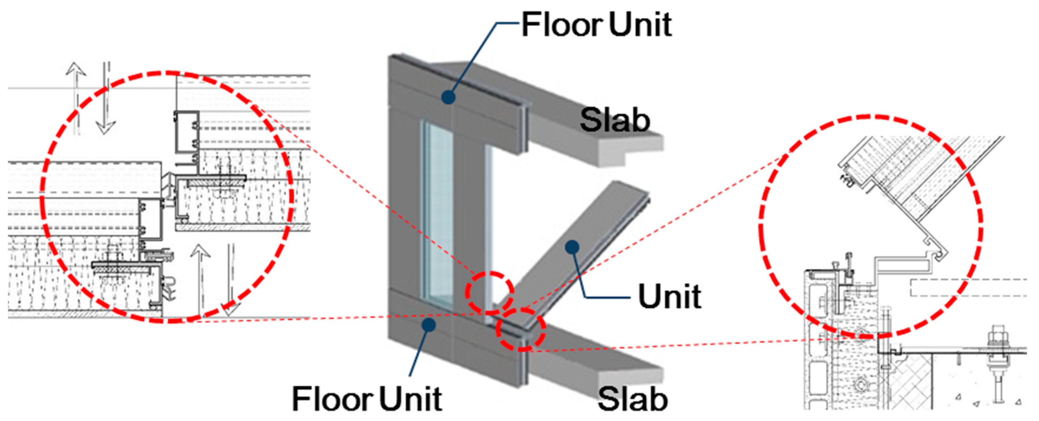
As an envelope applicable to multi-unit housings, this study developed a detachable EWP with flexibility and easy maintenance. It can be prefabricated at a workshop and installed on site. This panel was developed to ensure long-term usage by making EWPs attachable and detachable to improve the performance of external walls. The EWP was made of floor units and units as shown in Figure 1. Upper slabs and lower slabs were connected by the floor units of EWP. Units of EWP were installed in a vertical direction from each floor. Floor units and units were fabricated with the same materials. From the outside to the inside, the EWP consisted of 30 mm of extruded cement panel, a 25 mm insulation board, and an aluminum frame for the exterior side, followed by 2 sheets of 85 mm glass wool, another 10 mm insulation board, and a 9 mm cellulose fiber-reinforced cement board for the interior side as shown in Table 1.
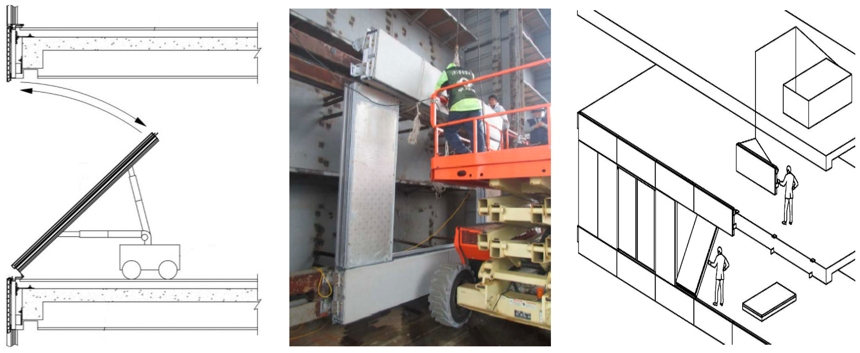
As shown in Figure 2, floor units were installed by fixing them to each slab, and units could be assembled with a tilt-in method from the interior side. Depending on the size and weight of the EPW, it could be transported and installed using small-scale equipment. The use of modularized units makes it easy to install them on site. In South Korea, the external wall is constructed by concrete and is installed inside insulation, as with most apartments. The advantage of this method is that it can shorten the construction period. On the other hand, in general, installing outside insulation requires the installation of scaffolding or gondola and so on.
2.2. Basic Performance Experiment of EWP (Methods and Results)
After fabricating the EWP, an actual-size mock-up experiment was carried out to evaluate its environmental and structural performance as a basic building envelope. Performance evaluation items included a thermal cycling test, air leakage test, static and dynamic water penetration test, structural performance test, story displacement test, and residual strain test. For the thermal cycling test, heating was maintained in the chamber at 24 °C for one hour, according to the temperature condition of AAMA (American Architectural Manufacturers Association) 501.5. After the temperature was kept at 82 °C for two hours, it was slowly lowered to −18 °C for 2 h, which was then maintained for 2 h. After that, the temperature was increased to 24 °C for one hour. This 8-h cycle was repeated three times in 24 h. The air leakage test was conducted by keeping the pressure at +7.6 kgf/m2 (the standard test pressure) and measuring the air leakage from the specimen. The water penetration test was conducted by keeping 30.4 kgf/m2 of positive pressure and spraying 204 L/m2 for 15 min, and measuring water penetration. The story displacement test was conducted by imposing the displacement of 9.4 mm (L/300) both left and right horizontally and examining if the functions and appearances of all parts have problems. The residual strain test was conducted by keeping the positive pressure (75%) and negative pressure (150%) of the designed wind load of the specimen for 10 s and then removing the pressure, and measuring the residual strain of each part.
Figure 3 shows flowchart of the experiment to evaluate each performance item. The experimental methods and criteria are shown in Table 2. The performance of the building envelope that connected EWP with windows was evaluated in accordance with the standard test method for the structural performance of external windows, curtain walls, and doors. Figure 4 shows the installation of the experimental subject and its performance testing.
As shown in Table 2, the mock-up test results confirmed that the EWP met the basic environmental and structural performance requirements as a building envelope. Therefore, its thermal performance was evaluated next.
3. Thermal Properties of the Developed EWP
3.1. Model and Method
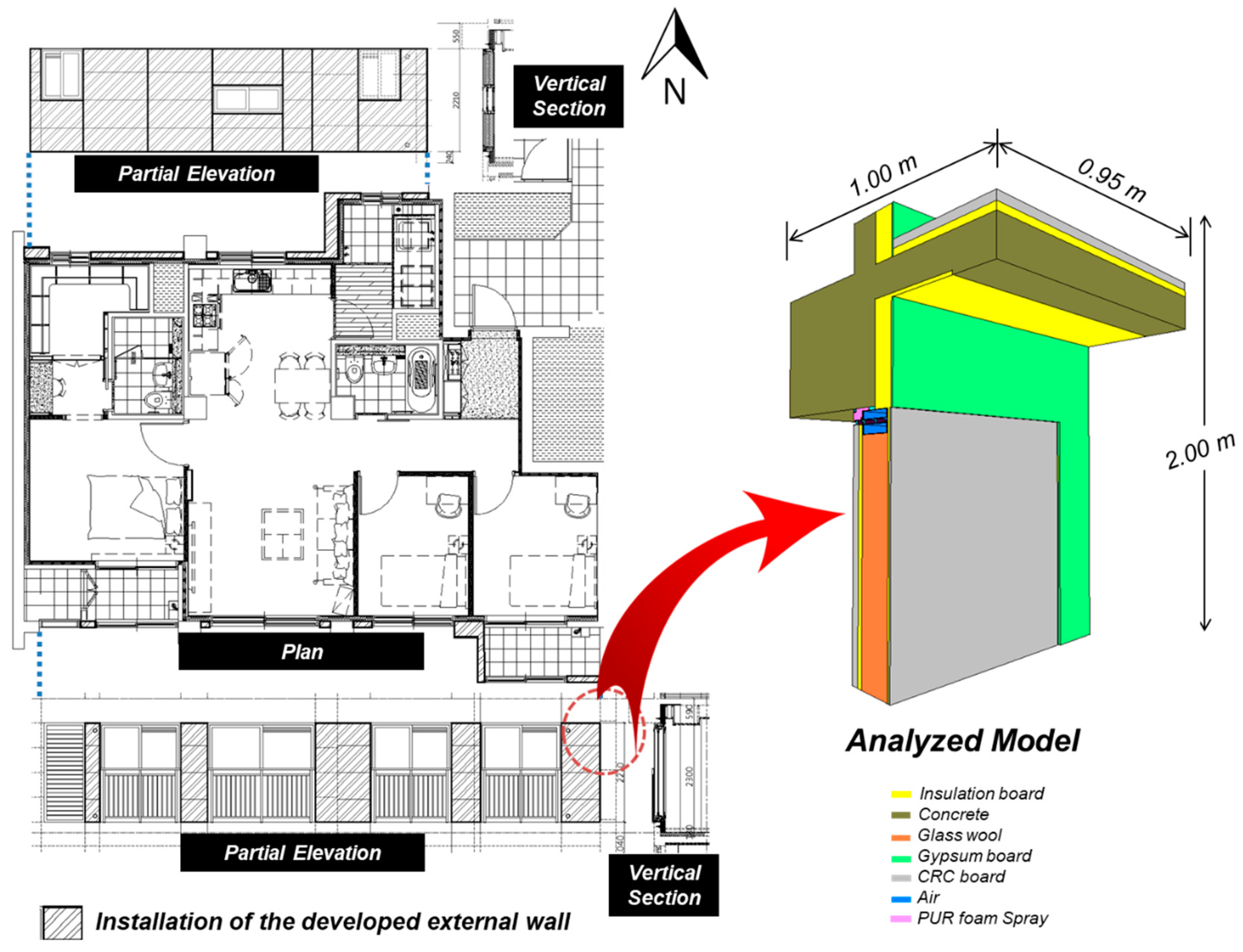
Figure 5 shows the floor plan of a household where the developed EWP is going to be installed. The floor plan had a size of 59 m2. The house had three bedrooms, one kitchen, and two bathrooms. The EWP was planned to be installed at the north and south of the plan. Figure 5 shows a partial cross-section drawing of the EWP. The image on the right of Figure 5 shows a simulation model to evaluate its thermal properties. It shows that the ceiling part is joined with the developed EWP and the insulated-concrete wall of an adjacent household. The insulated-concrete wall had 140 mm concrete, 110 mm insulation materials with a thermal conductivity of 0.03 W/(mK), and 9.5 mm gypsum board.
The surface temperature of the interior side of the EWP and the possibility of the occurrence of condensation were assessed through this analysis model. The PHYSIBEL TRISCO program was used for the steady-state 3-dimensional heat transfer analysis [27].
3.2. Conditions for Heat Transfer Simulation
Table 3 shows the boundary conditions for simulation. The outdoor temperature and indoor temperature were set at −20 °C and 25 °C, respectively, in accordance with the Korean Design Standard for Preventing Condensation in Apartments [28].
The analysis model was made using the PHYSIBEL program. Table 4 shows the thermal properties of each material.
3.3. Results
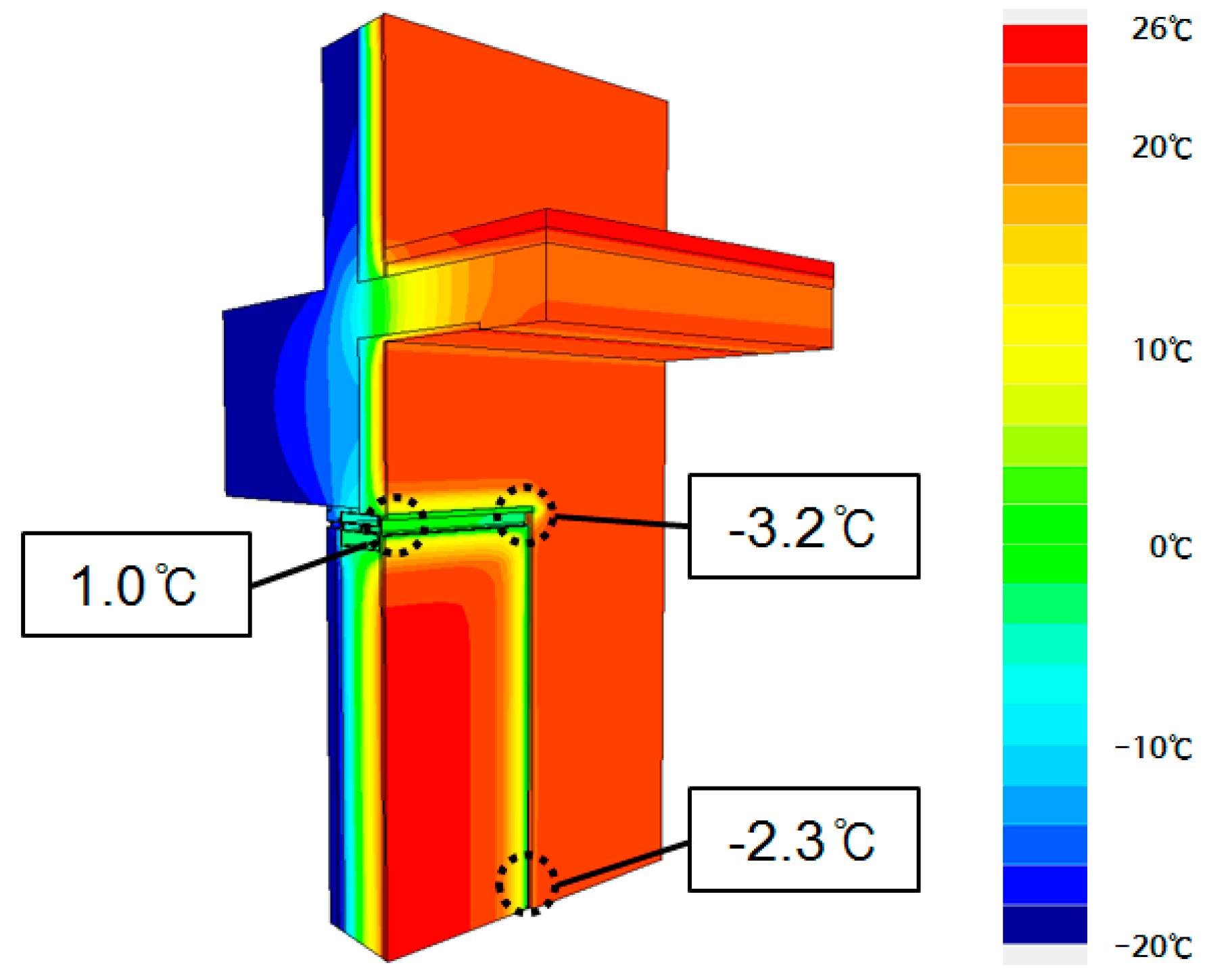
Figure 6 shows the results of the thermal performance analysis. The whole indoor surface temperature was estimated at a relatively high temperature of approximately 22 °C due to the use of insulation materials on the interior side. However, the indoor surface temperature at the connection parts of the EWP was much lower. Because connection parts were installed with only three layers of weather strip silicone gaskets without any insulation, these joints showed the lowest indoor surface temperature of −3.2 °C, −2.3 °C, and 1.0 °C, respectively. Because boundary conditions were set at an indoor temperature of 25 °C, an indoor humidity of 50%, and a dew point temperature of 13.9 °C, condensation was expected to occur during winter, indicating the need for the improvement of insulation performance.
According to the analysis model, heat loss of the EWP was measured at 68 W. Its effective thermal transmission was estimated to be 0.72 W/(m2K) by considering linear thermal transmission rates at the connection parts. The heat loss of the insulated-concrete wall was estimated at 40 W. The effective thermal transmittance of the insulated concrete wall in consideration of the linear thermal transmittance at the ceiling part was estimated to be 0.42 W/(m2K). Given these results, the EWP had a lower thermal performance by approximately 70% than that of the insulated concrete wall.
3.4. Measures for Improvement of Thermal Performance and Results
As shown in Table 5, three countermeasures were taken to improve the thermal performance of the connection parts. The first improvement method was to install insulation materials at the connection parts. The second method was to insert a thermal breaker in the middle of the aluminum frame. The third method was to use both the first and second methods. According to the analysis results of the above three improvement methods, for the indoor surface temperature of the first and third methods with added insulation materials, the lowest temperature was measured at 16.5 °C. The temperature was higher than the dew point temperature of 13.9 °C, indicating that these two methods could prevent condensation. However, the second improvement measure with an inserted thermal breaker showed the lowest indoor surface temperature of 5.7 °C, lower than the dew point temperature. Thus, it is desirable to install insulation materials at connection parts on the interior side to improve insulation performance and prevent condensation.
Table 6 shows the heat losses and linear thermal transmittance at the slabs and connection parts of the EWP and three improvement measures. The linear thermal transmittance is the heat flow rate divided by length and by temperature that is lost through the region of a thermal bridge in the steady state [25]. The thermal bridges are situated at the junction of walls, floors, roofs and building elements are characterized by a linear thermal transmittance as the ψ-value in W/(mK) [30].
Linear transmittance can be expressed as Equation (1):
where
- ψ—linear thermal transmittance [W/(mK)],
- —heat conduction coefficient calculated by two-dimensional computation [W/(mK)],
- —thermal transmittance of computation [W/(m2K)],
- —length to thermal bridge [m].
According to the heat losses shown in Table 6, the EWP had a heat loss of 68 W, the first measure (Alt-1) had a loss of 49.2 W, and the second measure (Alt-2) had a loss of 51.9 W. For the external walls (Alt-3) with additionally installed insulation materials and thermal breakers into the aluminum frame, the heat loss was 42.1 W, indicating a heat performance improvement of approximately 62%. Because there were no other improvement measures for slabs where heat bridges occurred, the linear thermal transmittances of the slabs were equally at 0.58 W/(mK). Depending on the improvement measures, the linear thermal transmittance at the horizontal and vertical connection parts ranged from 0.03 W/(mK) to 0.57 W/(mK). Heat losses of the EPW, three measures and the insulated concrete wall were calculated by using effective thermal transmittance considering linear thermal transmittance. The heat loss of the insulated concrete wall was lower than that of EPW because insulated concrete wall has no connection parts with thermal bridges, as presented in Table 6.
4. Unsteady State Thermal Characteristics of the EWP
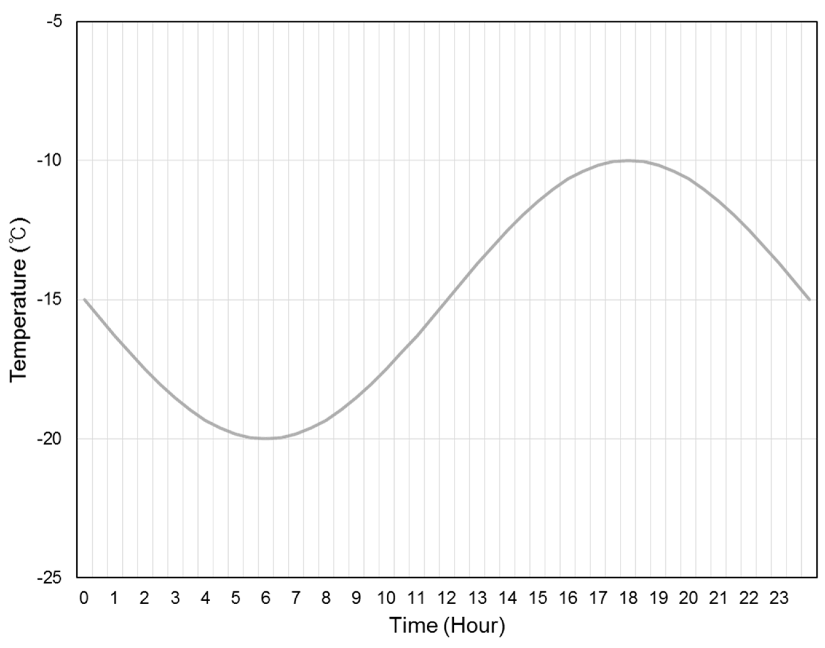
To evaluate the thermal performance of the EPW, an unsteady state 3-dimensional heat transfer analysis was also carried out for models with the improvement measures. For the simulation, the time step was 10 min, the calculation duration was 3 days, and there were five iteration cycles. Figure 7 shows the 24-h temperature distribution on the coldest winter day in South Korea. The temperature distribution had a lowest level of −20 °C and a highest level of −10 °C.
Figure 8 shows the heat loss of each model based on 24-h temperature distribution. The EWP had a maximum heat loss of 89.8 W and a minimum heat loss of 79.2 W. In the case of Alt-1, which had added insulation at the connection parts, the maximum heat loss was 59 W, while the minimum heat loss was 51.8 W. In the case of Alt-3, which had added insulation at the connection parts and inserted thermal breakers to the aluminum frame, the maximum heat loss was estimated at 50.8 W, (which was higher by approximately 4 W than that of the existing insulated concrete wall), whereas the minimum heat was estimated at 44.9 W (which was higher by approximately 1.7 W than that of the existing insulated concrete wall). These results confirm that if connection parts have more insulation, the disparity between the maximum heat loss and the minimum heat loss can be narrowed.
As seen in Figure 8, the existing insulated concrete walls had the lowest heat loss at 12:00, while the developed EWP had the lowest heat loss at 08:00. Because the existing insulated-concrete walls had a heavy-weight structure compared to the EWP, there was a difference of 4 h in terms of time lags [31]. Due to the light weight of the EWP, it had a shorter time lag. Thus, it was subjected to greater influence by outside temperatures than the existing insulated-concrete walls.
5. Discussion and Conclusions
Unsteady state thermal heat transfer characteristics such as the time lag and heat loss of the EWP were evaluated in this study. Although the light weight of EWP provides better constructability, it is necessary to consider energy and indoor thermal comfort at the same time [32].
Existing heat transmittance can be estimated by conducting a one-dimensional computation of insulation performance on mixed materials. The present study adopted a three-dimensional computation concept to estimate the effective thermal transmittance of the EPW by measuring the linear thermal transmittance induced by a heat bridge at slabs as well as the linear thermal transmittance at vertical and horizontal connection parts. Effective thermal transmittance is the heat transfer unit area and temperature that is lost through the thermal bridge [33]. Effective thermal transmittance was estimated in consideration of heat transmittance of the EWP, the linear thermal transmittance of its slabs, and the linear thermal transmittance of the connection parts. It was also estimated in consideration of the size of the EWP, the area size for construction, and thermal bridge effects [34,35]. The difference between the effective thermal transmittance with multi-dimensional calculation-considered linear thermal transmittance and thermal transmittance with one-dimensional calculation is very high [36,37]. In the building sector, the thermal characteristics of the building envelope are needed to analyze the effective thermal transmittance and linear thermal transmittance concerning thermal bridges [21,33].
The effective thermal transmittance was calculated using the Equation (2).
where
- —effective thermal transmittance [W/(m2K)],
- —thermal transmittance calculated by one-dimensional computation [W/(m2K)],
- —area [m2],
- —linear thermal transmittance [W/mK],
- —length to thermal bridge [m].
Table 7 shows the estimation results of the effective thermal transmittance of the EWP with improvement measures. It is judged that when calculating heating and cooling loads in the future, it will be necessary to estimate energy consumption more accurately through the computation of effective thermal transmittance.
This research introduced the newly developed EWP. To assess the possibility of its application to real apartments, this study carried out a simulation to analyze the thermal properties of the EWP and measures to prevent condensation. This study evaluated the linear thermal transmittance of EWP through a three-dimensional computation, analyzed the effective thermal transmittance of the envelope in reflection of these results, and identified its unsteady state thermal characteristics.
Author Contributions
All authors have contributed substantially. Writing and editing, G.H.; data analysis, S.-W.L.; investigation, J.-Y.K.; supervision, H.-G.K.
Funding
This study was made possible by financial support from part of results a major research project conducted by the Korea Ministry of Land, Infrastructure and Transport, Residential Environment Research Project in 2019 (Project No.: 19RERP-B082173-06).
Acknowledgments
We would like to acknowledge the research group of long-life housings.
Conflicts of Interest
The authors declare no conflict of interest.
References
- Ministry of Land. Infrastructure and Transport Statistic System In 2017. Available online: http://www.mlit.go.jp/road/road_e/q1_history_4.html (accessed on 8 February 2019).
- Mo, J.H.; Lee, Y.S. Typological Analysis of the Flexibility Concept for Sustainable Housing. KIEAE J. 2003, 3, 59–66. [Google Scholar]
- Lee, S.; Kim, S.; Na, Y. Comparative analysis of energy related performance and construction cost of the external walls in high-rise residential buildings. Energy Build. 2015, 99, 67–74. [Google Scholar] [CrossRef]
- Hong, W.-K.; Lim, G.-T.; Park, S.-C.; Kim, J.T. Energy efficiencies of linear-shaped multi-residential apartment buildings built with hybrid structural systems. Energy Build. 2012, 46, 30–36. [Google Scholar] [CrossRef]
- Lee, S.; Joo, J.; Kim, J.T.; Kim, S. An Analysis of the CO2 Reduction Effect of a Column-Beam Structure Using Composite Precast Concrete Members. Indoor Build. Environ. 2011, 21, 150–162. [Google Scholar] [CrossRef]
- Kang, J.-Y.; Kim, H.-G. Economic Evaluating of Long Span Structural System in Apartment Building. Proc. J. Korean Hous. Assoc. 2014, 26, 53–56. [Google Scholar]
- Kim, B.K.; Suk, S.J.; Lee, U.K.; An, S.H.; Kang, K.I. A study on the economic analysis of high-rise residential-commercial building that is made by precast concrete. J. Korea Inst. Build. Constr. 2005, 15, 89–97. [Google Scholar] [CrossRef]
- Hong, W.-K.; Lee, G.; Lee, S.; Kim, S. Algorithms for in-situ production layout of composite precast concrete members. Autom. Constr. 2014, 41, 50–59. [Google Scholar] [CrossRef]
- Kwon, N.Y.; Lee, S.H.; Jang, L.J.; Yi, S.H. A study on the Characteristics of Flexible Unit Plan of Apartment. AIK 2007, 2, 315–318. [Google Scholar]
- Metin, B.; Tavil, A. Environmental assessment of external wall cladding construction. Archi. Sci. Rev. 2014, 57, 215–226. [Google Scholar] [CrossRef]
- Manioğlu, G.; Yilmaz, Z. Economic evaluation of the building envelope and operation period of heating system in terms of thermal comfort. Energy Build. 2006, 38, 266–272. [Google Scholar] [CrossRef]
- Azari, R. Integrated energy and environmental life cycle assessment of office building envelopes. Energy Build. 2014, 82, 156–162. [Google Scholar] [CrossRef]
- Ozel, M. Effect of insulation location on dynamic heat-transfer characteristics of building external walls and optimization of insulation thickness. Energy Build. 2014, 72, 288–295. [Google Scholar] [CrossRef]
- Soler, D.; Salandin, A.; Micó, J.C. Lowest thermal transmittance of an external wall under budget, material and thickness restrictions: An integer linear programming approach. Energy Build. 2018, 158, 222–233. [Google Scholar] [CrossRef]
- Bojic, M.; Yik, F.; Leung, W. Thermal insulation of cooled spaces in high rise residential buildings in Hong Kong. Energy Conver. Manag. 2002, 43, 165–183. [Google Scholar] [CrossRef]
- Bojić, M.L.; Loveday, D.L. The influence on building thermal behavior of the insulation/masonry distribution in a three-layered construction. Energy Build. 1997, 26, 153–157. [Google Scholar] [CrossRef]
- Al-Sanea, S.A.; Zedan, M.F. Effect of insulation location on thermal performance of building walls under steady periodic conditions. Int. J. Ambient Energy 2011, 22, 59–72. [Google Scholar] [CrossRef]
- Ozel, M.; Pihtili, K. Optimum location and distribution of insulation layers on building walls with various orientations. Build. Environ. 2007, 42, 3051–3059. [Google Scholar] [CrossRef]
- Kontoleon, K.J.; Eumorfopoulou, E.A. The influence of wall orientation and exterior surface solar absorptivity on time lag and decrement factor in the Greek region. Renew. Energy 2008, 33, 1652–1664. [Google Scholar] [CrossRef]
- Kontoleon, K.J.; Bikas, D.K. The effect of south wall's outdoor absorption coefficient on time lag, decrement factor and temperature variations. Energy Build. 2007, 39, 1011–1018. [Google Scholar] [CrossRef]
- Oh, J.-M.; Song, J.-H.; Lim, J.-H.; Song, S.-Y. Analysis of Building Energy Savings Potential for Metal Panel Curtain Wall Building by Reducing Thermal Bridges at Joints Between Panels. Energy Procedia 2016, 96, 696–709. [Google Scholar] [CrossRef] [Green Version]
- Yuan, J. Impact of Insulation Type and Thickness on the Dynamic Thermal Characteristics of an External Wall Structure. Sustainability 2018, 10, 8. [Google Scholar] [CrossRef]
- Morgan, C.M.; McGowan, L.M.; Flick, L.D. Case Study of Mechanical Control of Condensation in Exterior Walls. J. Test. Eval. 2011, 39, 250–259. [Google Scholar] [CrossRef]
- Gorrell, T.A. Condensation Problems in Precast Concrete Cladding Systems in Cold Climates. J. Test. Eval. 2011, 39, 630–636. [Google Scholar]
- ISO. Thermal Bridges in Building Construction–Heat Flows and Surface Temperatures–Detailed Calculations. 2017. Available online: https://www.iso.org/standard/40967.html (accessed on 8 February 2019).
- ISO13786. Thermal Performance of Building Components–Dynamic Thermal Characteristics–Calculation Methods. 2007. Available online: https://www.iso.org/standard/65711.html (accessed on 8 February 2019).
- Physibel, Physibel Trisco Manual. Available online: http://www.physibel.be/v0n2tr.htm (accessed on 6 February 2019).
- Ministry of Land. Korean Design Standard for Preventing Condensation in Apartments. 2016. Available online: http://www.molit.go.kr (accessed on 8 February 2019).
- Ministry of Land. Transport The Code for Energy-efficient Building Design. In Notice; 2017. Available online: http://www.molit.go.kr (accessed on 8 February 2019).
- Larbi, A.B. Statistical modelling of heat transfer for thermal bridges of buildings. Energy Build. 2005, 37, 945–951. [Google Scholar] [CrossRef]
- Leccese, F.; Salvadori, G.; Asdrubali, F.; Gori, P. Passive thermal behaviour of buildings: Performance of external multi-layered walls and influence of internal walls. Appl. Energy 2018, 225, 1078–1089. [Google Scholar] [CrossRef]
- Shaik, S.; Talanki Puttaranga Setty, A.B. Influence of ambient air relative humidity and temperature on thermal properties and unsteady thermal response characteristics of laterite wall houses. Build. Environ. 2016, 99, 170–183. [Google Scholar] [CrossRef]
- Kim, J.-H.; Kim, S.-M.; Kim, J.-T. Simulation Performance of Building Wall with Vacuum Insulation Panel. Procedia Eng. 2017, 180, 1247–1255. [Google Scholar] [CrossRef]
- Sprengard, C.; Holm, A.H. Numerical examination of thermal bridging effects at the edges of vacuum-insulation-panels (VIP) in various constructions. Energy Build. 2014, 85, 638–643. [Google Scholar] [CrossRef]
- Wakili, K.G.; Bundi, R.; Binder, B. Effective thermal conductivity of vacuum insulation panels. Build. Res. Inf. 2004, 32, 293–299. [Google Scholar] [CrossRef]
- Tzifa, V.; Papadakos, G.; Papadopoulou, A.G.; Marinakis, V.; Psarras, J. Uncertainty and method limitations in a short-time measurement of the effective thermal transmittance on a building envelope using an infrared camera. Int. J. Sustain. Energy 2014, 36, 28–46. [Google Scholar] [CrossRef]
- Tenpierik, M.; Cauberg, H. Analytical Models for Calculating Thermal Bridge Effects Caused by Thin High Barrier Envelopes around Vacuum Insulation Panels. J. Build. Phys. 2016, 30, 185–215. [Google Scholar] [CrossRef]
Figure 1.
Floor unit and unit of the EWP.

Figure 2.
Transportation and installation of the developed EWP using small-scale equipment.

Figure 3.
Mock-up test.

Figure 4.
Mock-up test.

Figure 5.
Floor plan, cross-section, and analysis model of the EWP.

Figure 6.
Interior surface temperature distribution of the EWP.

Figure 7.
Outside temperature for the analysis of unsteady state thermal characteristics.

Figure 8.
Distribution of heat losses by unsteady state models.


Table 1.
Material layers of the developed external wall panel (EWP).
| Type | Layers |
|---|---|
| Floor Unit/Unit | ECP 1 (35 mm) + PIR Board 2 (25 mm) + Glass Wool (85 mm + 85 mm) + PIR Board 2 (10 mm) + CRC Board 3 (9 mm) |
1 ECP: extruded cement panel. 2 PIR Board: polyisocyanurate board. 3 CRC Board: cellulose fiber-reinforced cement board.
Table 2.
Test methods and results for performance evaluation
| Items | Test Methods | Allowance | Measured Results | |
|---|---|---|---|---|
| Thermal cycling test | AAMA 501.5-07 | Hot cycle (+82 °C) Cold cycle (−18 °C) 3rd cycle | No damage | No damage |
| Pre-load test | ASTM E330-14 | 50% of design wind load | No damage | No damage |
| Air leakage | ASTM E283-04 (for window) | +7.6 kgf/m2 | 1.09 CMH/m2 | 1.06 CMH/m2 |
| Water penetration | ASTM E 331 (uniform Static air difference)/AAMA 501.1-05 (dynamic pressure) | 20% of design wind load | No uncontrolled water leakage | No leakage |
| Structural performance | ASTM E 330-14 | 1. 100% maximum displacement test (+50% → +100% → −50% → −100%) 2. 150% residual strain test (+75% → +150% → −75% → −150%) | 1. L/175 (=12.43 mm) 2. No permanent damage | 1.53 mm (OK) |
| Story displacement | AAMA 501.4-09 | L/300 (high-occupancy assembly) | No wall components may fall off | No deflection |
| Residual strain | ASTM E330-02 | 75% and 150% of positive and negative design wind load | 2L/1000 (=4.35 mm) | 1.33 mm (positive) 1.31 mm (negative) |
| Full specimen area: 4064 mm (W) × 3405 mm (H), PVC sliding window: 1800 mm (W) × 2085 mm (H) | ||||
Table 3.
Boundary Conditions.
| Set-Point Temperatures | Set-Point Relative Humidity | Surface Heat Transfer Coefficient | |
|---|---|---|---|
| Outdoor | −20 °C | - | 23.25 W/(m2 K) |
| Indoor | 25 °C | 50% | 9.09 W/(m2 K) |
Table 4.
Thermal properties of materials [29].
Table 4.
Thermal properties of materials [29].
| Materials | Thermal Conductivity [W/(mK)] | Specific Heat Capacity [J/(kgK)] | Density [kg/(m2)] |
|---|---|---|---|
| Aluminum | 160.00 | 880 | 2700 |
| Cement | 1.00 | 1000 | 1800 |
| Concrete | 1.60 | 1000 | 2200 |
| Gasket | 1.00 | 1000 | 1150 |
| Sealant | 1.00 | 1000 | 1450 |
| Gypsum board | 0.18 | 1000 | 900 |
| Thermal breaker | 0.30 | 1000 | 1000 |
| Expanded polystyrene | 0.028 | 1470 | 25 |
Table 5.
Insulation improvement measures for the developed EWP and results of indoor surface temperature.
Table 5.
Insulation improvement measures for the developed EWP and results of indoor surface temperature.
| Improvement Measures | Simulation Models with Improved Insulation Performance | Results of Indoor Surface Temperature | |
|---|---|---|---|
| ➊ EWP |  |  |  |
| <Vertical Section> | |||
 | |||
| <Horizontal Section> | |||
| ➋ Alt-1 (added insulation at connection parts) |  |  | |
| <Vertical Section> | |||
 | |||
| <Horizontal Section> | |||
| ➌ Alt-2 (insertion of thermal breaker) |  |  | |
| <Vertical Section> | |||
 | |||
| <Horizontal Section> | |||
| ➍ Alt-3 (added insulation + insertion of thermal breaker) |  |  | |
| <Vertical Section> | |||
 | |||
| <Horizontal Section> | |||
Table 6.
Heat loss and linear thermal transmittance dependent on improvement measures.
| ➊ EWP | ➋ Alt-1 | ➌ Alt-2 | ➍ Alt-3 | Insulated Concrete Wall | ||
|---|---|---|---|---|---|---|
| Heat loss (W) | 68.0 | 49.2 | 51.9 | 42.1 | 40 | |
| Linear thermal transmittance [W/(mK)] | Slab | 0.58 | 0.58 | 0.58 | 0.58 | 0.58 |
| Horizontal connection parts | 0.57 | 0.18 | 0.15 | 0.03 | 0 | |
| Vertical connection parts | 0.49 | 0.18 | 0.22 | 0.13 | 0 | |
Table 7.
Effective thermal transmittance by improvement measures.
| ➊ EWP | ➋ Alt-1 | ➌ Alt-2 | ➍ Alt-3 | Insulated Concrete Wall | |
|---|---|---|---|---|---|
| Effective Thermal Transmittance [W/(m2K)] | 0.72 | 0.52 | 0.55 | 0.44 | 0.42 |
© 2019 by the authors. Licensee MDPI, Basel, Switzerland. This article is an open access article distributed under the terms and conditions of the Creative Commons Attribution (CC BY) license (http://creativecommons.org/licenses/by/4.0/).
Share and Cite
MDPI and ACS Style
Hong, G.; Lee, S.-W.; Kang, J.-Y.; Kim, H.-G. Thermal Behavior and Measures to Prevent Condensation of a Newly Developed External Wall Panel. Sustainability 2019, 11, 912. https://0-doi-org.brum.beds.ac.uk/10.3390/su11030912
AMA Style
Hong G, Lee S-W, Kang J-Y, Kim H-G. Thermal Behavior and Measures to Prevent Condensation of a Newly Developed External Wall Panel. Sustainability. 2019; 11(3):912. https://0-doi-org.brum.beds.ac.uk/10.3390/su11030912
Chicago/Turabian StyleHong, Goopyo, Suk-Won Lee, Ji-Yeon Kang, and Hyung-Geun Kim. 2019. "Thermal Behavior and Measures to Prevent Condensation of a Newly Developed External Wall Panel" Sustainability 11, no. 3: 912. https://0-doi-org.brum.beds.ac.uk/10.3390/su11030912
Note that from the first issue of 2016, this journal uses article numbers instead of page numbers. See further details here.