Study on Column-Top Seismic Isolation of Single-Layer Latticed Domes


1
Shanghai Institute of Disaster Prevention and Relief, Tongji University, Shanghai 200082, China
2
Department of Civil Engineering, Tongji University, Shanghai 200082, China
3
ARTS GROUP Co., Ltd., Suzhou 215000, China
4
College of Architecture and Urban Planning, Tongji University, Shanghai 200082, China
*
Author to whom correspondence should be addressed.
Sustainability 2019, 11(3), 936; https://0-doi-org.brum.beds.ac.uk/10.3390/su11030936
Submission received: 27 December 2018
/
Revised: 3 February 2019
/
Accepted: 7 February 2019
/
Published: 12 February 2019
(This article belongs to the Special Issue Resilience and Sustainability of Civil Infrastructures under Extreme Loads)
Abstract
:In this paper, a single-layer lamella reticulated dome with reinforced concrete bearings was studied, and a method of column-top isolation was proposed to improve the seismic performance of the whole structure, thereby avoiding too large support stiffness in engineering practice. A nonlinear time-history analysis showed that lead rubber bearings (LRB) can reduce the support reaction to a certain extent and make it distribute uniformly, reducing the support design requirements under frequent earthquakes. During rare earthquakes, the LRB was basically in the plastic state and the support reaction remained near the yield force, which was reduced greatly compared with that of the original structure. The bearing hysteresis curve was full, while the plasticity development degree of the upper reticulated dome was greatly reduced and the elasticity was basically maintained, thus achieving a good damping effect.
1. Introduction
A single-layer reticulated dome is an important form of space structure in China that combines the characteristics of skeletal structures and thin-shell structures with beautiful shapes, reasonable forces and simple structures that are widely used in various large and medium span buildings [1]. However, China is among the world’s most earthquake-prone countries, and some spatial structures in the Wenchuan earthquake demonstrated various degrees of earthquake disaster phenomena [2,3]. Common failure forms include lower support failure, bearing connection damage, excessive plastic deformation of the upper steel roof and overall collapse of the structure [4]. Therefore, it is very important to study the seismic behavior of reticulated domes and seismic isolation techniques. Isolation technology can effectively block seismic action and reduce the seismic response of a structure. It reduces the earthquake effect by prolonging the structure period and dissipating energy through additional damping, so that the structure displacement is controlled within the allowable range [5,6,7]. Early isolation technology has been primarily applied to support multi-story building foundations and bridge structures. With the development of structural vibration control technology and the increasing demand for seismic performance in large-scale engineering projects, this method has also gradually been applied to large span spatial structures. The roof of the Shanghai International Speedway News Center adopts a high isolation bearing—a new composite isolation bearing consisting of one basin bearing and four common rubber bearings—which effectively releases temperature stress and significantly reduces the seismic response of the structure [7]. The pyramid-shaped roof of the Ataturk Airport terminal in Turkey uses a column-top friction-pendulum isolation scheme [8].
To simplify the calculation, the roof structure is analyzed separately by the simply supported boundary, disregarding the dynamic interaction between the roof and the lower supporting structure in the engineering design. In fact, the existence and stiffness of the lower supporting structure will have an important influence on the seismic performance of the integral structure, especially when the stiffness of the supporting structure is much stronger than that of the upper roof. In this case, the seismic amplification effect of the structure is very significant, and the failure limit load of the superstructure can be greatly reduced. To meet the requirements of the construction in engineering practice when the supporting structure introduces more space frames, slabs, or shear walls, its support stiffness is generally large. To improve the seismic performance of this kind of "strong support" structure, this paper takes a single-layer spherical reticulated dome with a concrete bearing under the surface as its research subject. The common spherical steel bearing at the top of the column is replaced by an isolation lead rubber bearing in this study, and the seismic behavior of the structure before and after the isolation is compared and analyzed.
2. Integral Model of Dome and Support Structure
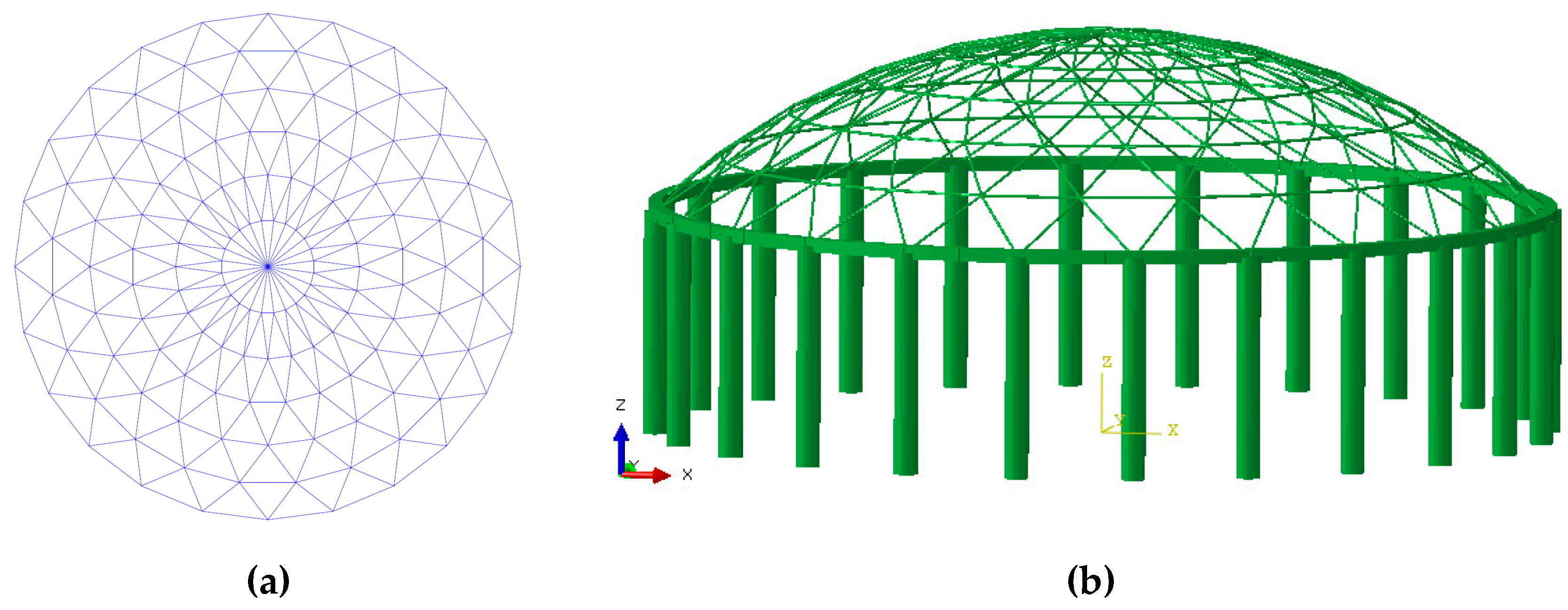
The roof structure analyzed in this paper is a single-layer spherical reticulated dome (Figure 1) with a span of 40 m, a vector span ratio of 1/5, a round steel pipe as the reticulated dome rod, a material of q235b steel, a circular members section of φ132 × 4, and radial and oblique rod sections of φ116 × 4. The lower support structure adopts the cylindrical-ring beam system. The column height is 10 m. To simulate the "strong support rigidity" condition, the column section diameter is set to 1.5 m, and the ring beam covers a 0.6 m × 0.6 m rectangular section. The whole structure contains 24 pillars, and the concrete strength grade of the beam and column is C30. Through refinement of finite element analysis in Abaqus, it is shown that when the diameter of the column cross section is 1.5 m, the damage factor of the lower supporting structure concrete is very small. The reticulated shell, the beam and column adopt B31 beam units based on the fiber bundle model. Steel adopts an ideal elastoplastic model. In order to achieve a certain calculation accuracy, all beam elements are controlled to a length of about 1 m during meshing. Material nonlinearity and geometric nonlinearity are considered simultaneously. A welded ball joint is used to connect the members of the upper reticulated dome rigidly, and a common spherical steel bearing or an isolation bearing is used to connect the ring beam between the reticulated shell and the lower support structure at the top of each column. The integral structural model is shown in Figure 1b.
3. Selection of a Seismic Isolation Device
In this paper, a lead rubber bearing is chosen as the isolation device. Lead has good mechanical properties, as its yield shear stress is relatively low at only approximately 10 MPa, the initial shear stiffness is higher, the shear modulus is approximately 130 MPa, and it is also the ideal elastoplastic body. Lead has good fatigue resistance for the plastic cycling load, and high-purity Pb (99.99%) is easy to obtain, which makes its mechanical properties more reliable. This article selects the Fuyo lead rubber bearing series product LRB600, produced by the Wuxi construction new material Limited Company [9]. Its mechanical performance parameters are shown in Table 1.
Therefore, this paper discusses two structural models: The original structure, whose column top adopts the common steel bearing, namely, the hinged connection, and the isolation structure whose column top is connected by the LRB.
The analytical model of the LRB adopts the rubber isolator unit in SAP2000 [10], as shown in Figure 2, which consists of six internal "springs" representing the components of axial, shearing, bending, and torsion. For each degree of freedom of the deformation, linear or nonlinear behavior can be specified independently, and the plasticity properties are based on the hysteresis behavior proposed by Wen (1976) [11] and Park, Wen, and Ang (1986) [12].
4. Results
First, the natural frequency of the structure before and after isolation was compared. Since the LRB is a nonlinear element, its stiffness is a function of the bearing deformation, and modal analysis is a linear perturbation analysis. To objectively evaluate the impact of the isolation device on the structural dynamic characteristics, the parameters of the LRB, including the equivalent stiffness and the equivalent damping ratio in the modal analysis, are shown in Table 1. As shown in Table 2, the natural frequency of the isolated structure was significantly lower than that of the original structure.
5. Analysis of Frequent Earthquake Response
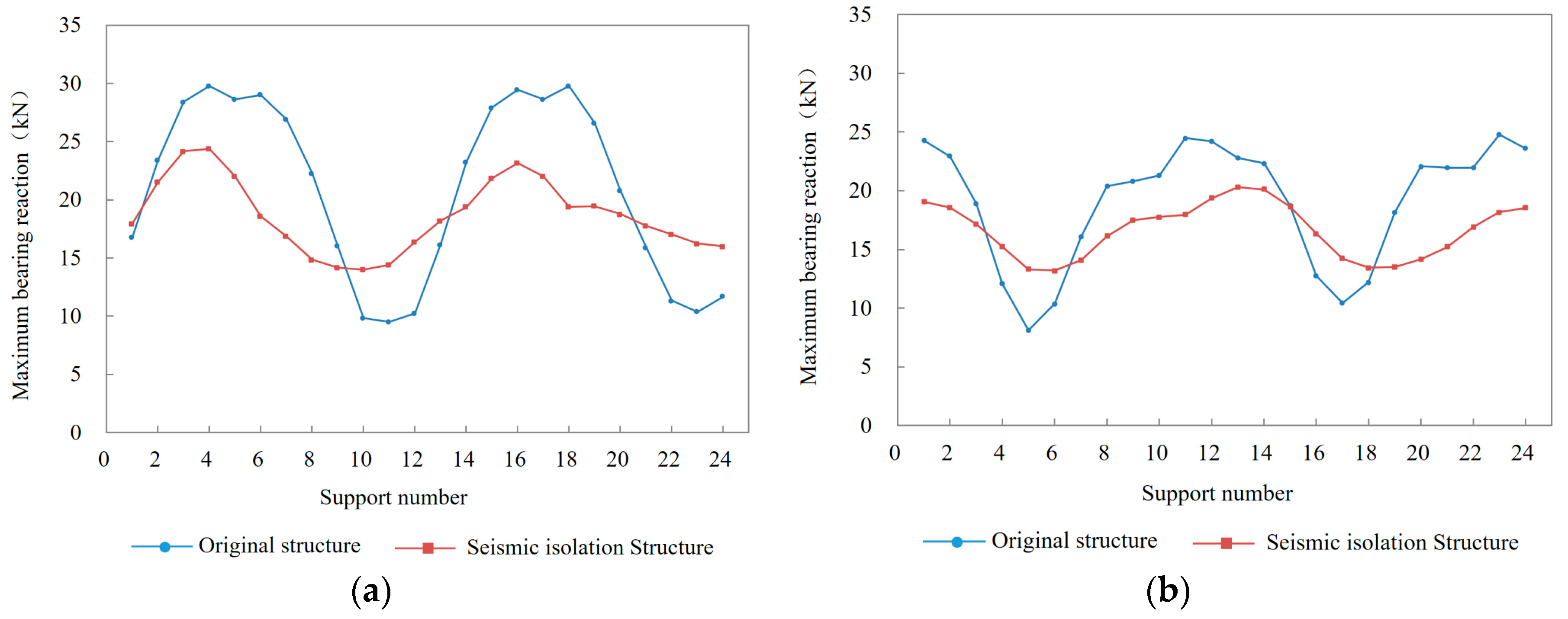
The acceleration peaks of the El Centro wave and Taft wave adjusted to 70 gal under frequent earthquakes were input into the structure in three directions, and the nonlinear time-history response was analyzed. The distribution curve of the reaction force envelope value of all 24 bearings at the top of the original structure and the isolated structure column are given in Figure 3. It was apparent that the distribution of the maximum bearing reaction force was very uneven for the original structure because of the uncertain direction of the action of the earthquake. The actual design was based on taking the most unfavorable bearing force, so the design requirements of the bearing were often relatively high and could easily act as a weak link during an earthquake. The bearing force distribution was relatively flat for the isolated structure, and the value of the force was lower than that of the original structure, which was beneficial to the design of the bearing and reduced the seismic effect of the transmission to the upper reticulated dome. A typical bearing in the sixth support position (Figure 3) is taken as an example.
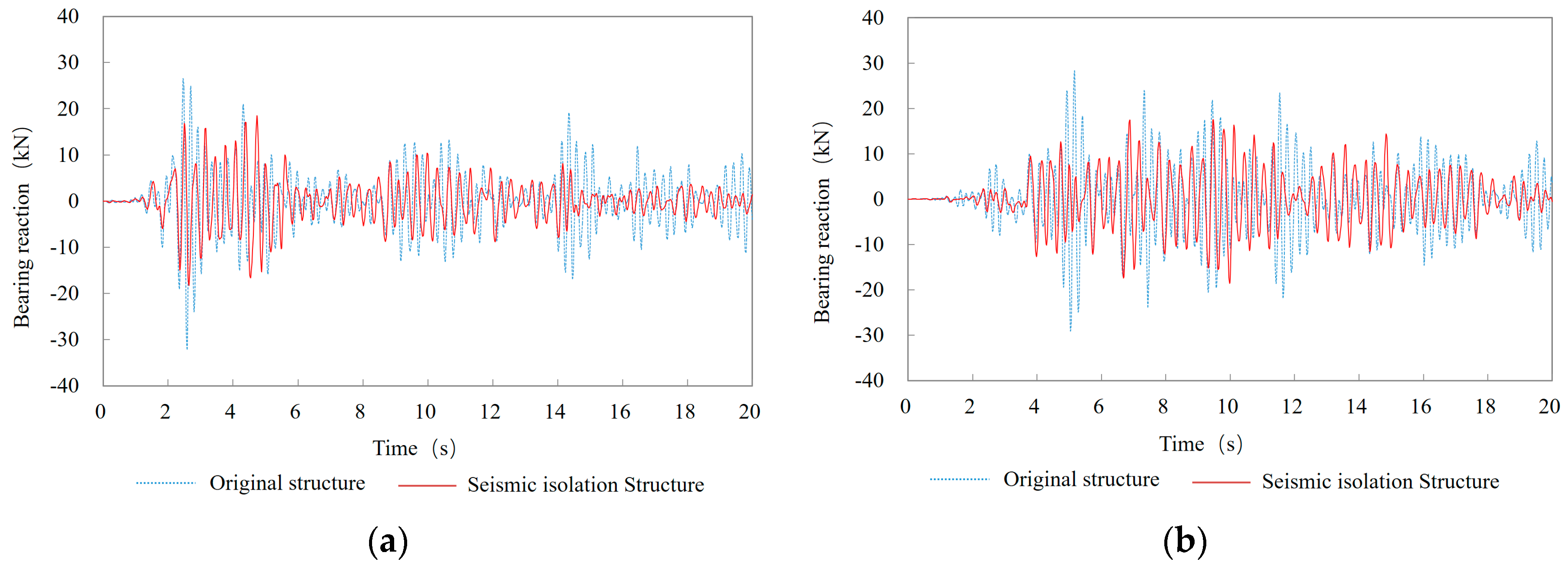
As shown in Figure 4 and Figure 5, under the El Centro and Taft waves, the maximum bearing reaction force of the original structure in the X direction was 32.11 kN and 29.01 kN, respectively, and the maximum bearing force of the isolation structure in the X direction was reduced to 18.45 kN and 18.59 kN, a decrease of 42.5% and 35.9%, respectively. The comparison for the time-history curve of the bearing No.6 between the original structure and the isolation structure is given in Figure 6; the structural reaction apparently decreased with the isolation bearing.
Under frequent earthquakes, all LRB supports did not reach their yield force, so the bearings were still in the initial elastic state. The typical hysteresis curve of the No. 6 bearing is given in Figure 7, which shows that the LRB did not dissipate any energy under frequent earthquakes and that the isolation effect was realized by prolonging the structure period.
The maximum displacement envelope value of all supports under the El Centro wave and Taft wave was 3.07 mm and 3.26 mm, respectively, which is within the elastic deformation range and can guarantee the normal use of the structure under earthquake or wind load.
6. Analysis of Rare Earthquake Response
The acceleration peak of the seismic wave was adjusted to the value of rare earthquakes stipulated in the specification, 400 gal, and then input into the structure basement in three directions in order to analyze the nonlinear time-history reaction. Compared with frequent earthquakes, the response of structures under rare earthquakes was very similar, but because of the plastic energy dissipation caused by most of the bearing in the yield state, the seismic isolation structure under rare earthquakes showed a better damping effect. Figure 8 and Figure 9 give the distribution curve of the reaction force envelope value of all 24 bearings at the top of the original structure and the isolated structure column. Note that the bearing reaction of the original structure under rare earthquakes is quite large, and the distribution is very uneven. Taking bearing No. 6 as an example, the resultant force of the two horizontal forces under the El Centro wave acted up to 188 kN, making the integral structure prone to fail early under the strong earthquake due to the support force. The bearing force of the isolated structure was basically located near the yield force, which greatly reduced the seismic action transmitted to the upper reticulated dome. The comparison of the time-history curve of bearing No. 6 in the X direction between the original structure and the isolation structure is given in Figure 10, showing that the structural reaction apparently decreased with the isolation bearing.
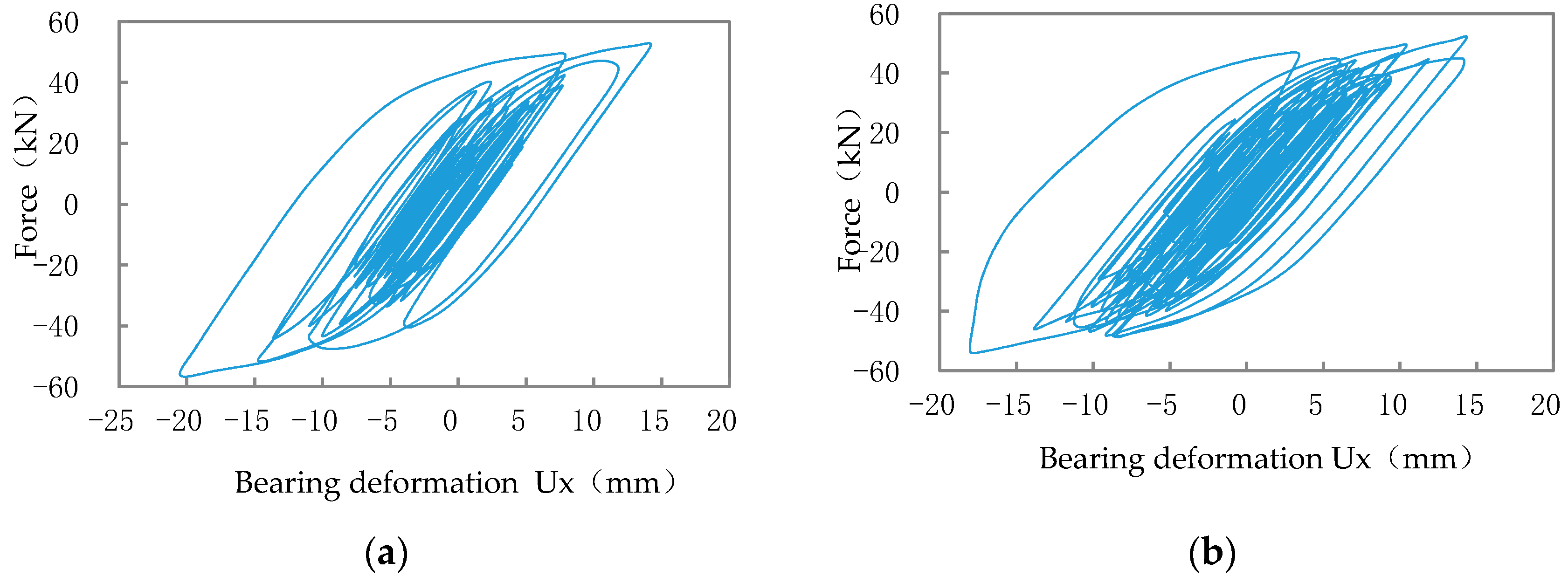
The typical hysteresis curve of the No. 6 bearing in the X direction is given in Figure 11, which shows that the hysteretic curve of the LRB under rare earthquakes was full, and the energy dissipation effect was significant. The maximum displacement of the bearing in the X direction under the El Centro wave and the Taft wave was 20.5 mm and 18.0 mm, respectively, which is less than the maximum allowable deformation of the bearing (according to the product specification gauge deformation of 400%).
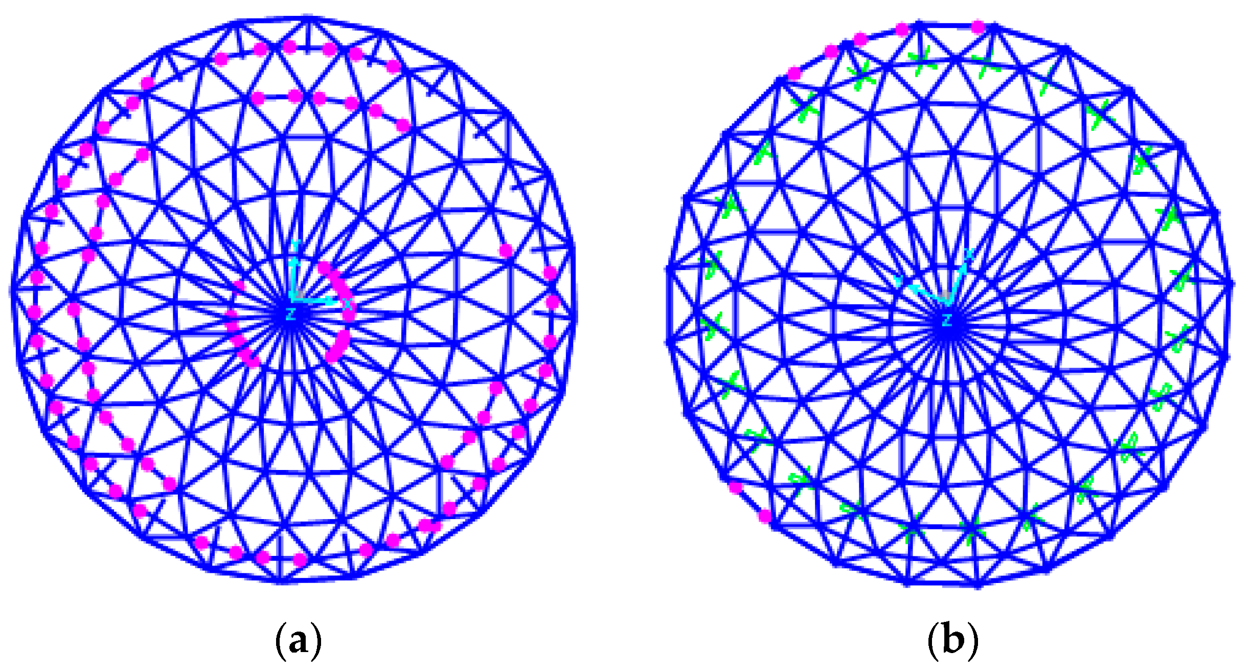
A comparison of the plastic development of the upper reticulated dome before and after the isolation is given in Figure 12 and Figure 13, which indicates more plastic development of the original structure under rare earthquakes, while the isolation structure was basically in an elastic state. The plastic deformation only occurs at the outer part of the lateral beam under the Taft wave.
7. Conclusions
The modal analysis of the structure before and after the isolation showed that the LRB can prolong the natural period of the structure effectively [13,14,15], thus avoiding the excellent period of earthquake motion and reducing the seismic action of the superstructure. Time-history analysis showed that the LRB can reduce the bearing reaction force to a certain extent under frequent earthquakes, the maximum reduction of which under the El Centro wave and Taft wave was up to 42.5% and 35.9%, respectively. The distribution of the bearing force tended to be uniform, which reduced the requirement of the bearing design. Under rare earthquakes, the LRB bearing was basically in a plastic state, and the bearing reaction force was maintained near the yield force, which decreased greatly compared with that of the original structure. The bearing hysteresis curve was full, the energy dissipation effect was significant, and the plasticity development degree of the upper reticulated shell was greatly reduced so that it was basically elastic.
Overall, for the strong support structure, the column-top seismic isolation method used in this paper is a new idea that effectively improves the seismic performance of the whole structure, from “resisting” to “eliminating”.
Author Contributions
Conceptualization, Y.Z.; methodology, Y.Z.; software, Y.C.; validation, X.F.; formal analysis, Y.C.; investigation, W.H.; resources, Y.C.; data curation, Y.C.; writing—original draft preparation, Y.C.; writing—review and editing, X.F.; visualization, X.F.; supervision, X.F.; project administration, Y.Z.; funding acquisition, Y.Z.
Funding
This research was funded by NATIONAL KEY R&D PROJECTS IN 13TH FIVE-YEAR OF CHINA, grant number 2016YFC0800209, 2017YFC0803300.
Conflicts of Interest
The authors declare no conflict of interest.
References
- Ming, G.; Tao, W. Application of reticulated shell structure. Archicreation 2000, 2, 48–51. [Google Scholar]
- Liu, W.; Deng, K. Preliminary investigation on earthquake damage of “5.12” Wenchuan in spatial structure. Sichuan Archit. 2009, 29, 112–113. [Google Scholar]
- Deng, K. Investigation on earthquake damage of Wenchuan large earthquake. China Steel Struct. Assoc. Spat. Struct. Bull. 2008, 3, 64–68. [Google Scholar]
- Qin, S.; Lu, J.; Dai, C. Design and stability analysis of large-span single-layer spherical reticulated shells. Spec. Struct. 2012, 28, 9–12. [Google Scholar]
- Feng, Y. Discussion on Seismic Mitigation and Isolation Schemes for High-speed Railway Large-span Continuous Girder Bridges. Earthq. Res. 2015, 38, 167–172. [Google Scholar]
- Liu, S.; Wei, X.; Zhang, C.; Ma, F. Analysis on Anti-mining Deformation and Anti-seismic Protection of Bridge Structure based on Isolation Technology. Earthq. Res. 2014, 37, 86–97. [Google Scholar]
- Zhuang, P.; Xue, S.; Li, B. Seismic Isolation Analysis of SMA-rubber Bearings in a Single-layer Spherical Lattice Shell Structure. Build. Struct. 2006, 11, 103–106. [Google Scholar]
- Shi, W.; Sun, H.; Li, Z.; Ding, M. High-Position Seismic Isolation of Press Center at Shanghai International Circuit. J. Tongji Univ. Nat. Sci. Ed. 2005, 33, 1576–1580. [Google Scholar]
- Constantinou, M.; Whittaker, A.S.; Velivasakis, E. Seismic evaluation and retrofit of the Ataturk international airport terminal building. In Proceedings of the 2001 Structural Congress and Exposition, Washington, DC, USA, 21–23 May 2001. [Google Scholar]
- Wuxi Construction Materials Co., Ltd. Fuyo Rubber Isolation Bearing Standard Product Design Data. Available online: http://fuyotech.com/Product.aspx?ptid=2 (accessed on 1 February 2019).
- Wen, Y.K. Method for random vibration of hysteretic system. J. Eng. Mech. Div.-ASCE 1976, 102, 249–263. [Google Scholar]
- Park, Y.J.; Wen, Y.K.; Ang, A.H.-S. Random vibration of hysteretic systems under bi-directional ground motions. Earthq. Eng. Struct. Dyn. 1986, 14, 543–557. [Google Scholar] [CrossRef]
- Beijing Golden Civil Engineering software Technology Co., Ltd. SAP2000 Chinese Version (Second Edition); People’s Transportation Press: Beijing, China, 2012; Available online: https://max.book118.com/html/2018/0428/163589441.shtm (accessed on 1 February 2019).
- Chiara, B.; Antonino, M. Dynamic testing and parameter identification of a base-isolated bridge. Eng. Struct. 2014, 60, 85–99. [Google Scholar]
- Corrado, C.; Chiara, B.; Claudio, A. Dynamic and static identification of base-isolated bridges using Genetic Algorithms. Eng. Struct. 2015, 102, 80–92. [Google Scholar]
Figure 1.
Layout of dome (a) single lamella spherical dome model, (b) model of integral structure.

Figure 2.
Mechanical model of a lead rubber bearing.
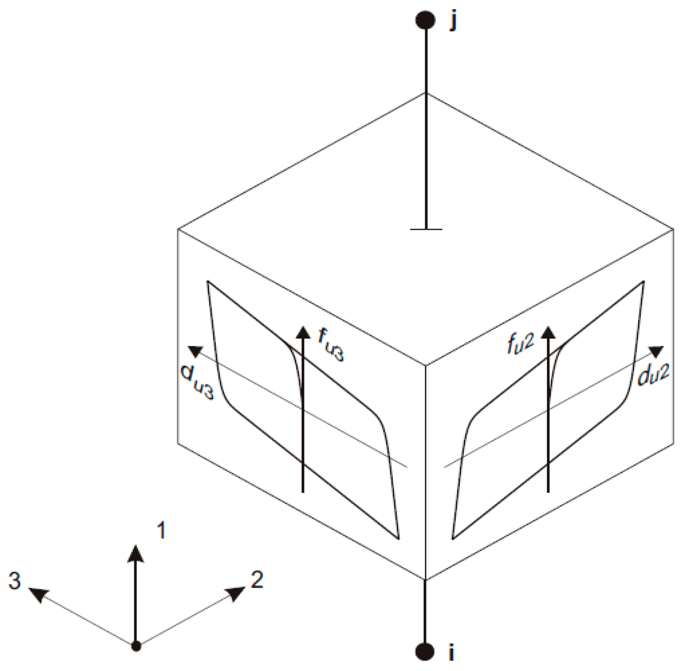
Figure 3.
Support position.

Figure 4.
Comparison of maximum inverse force distribution direction between original structure and seismic isolation structure under the El Centro wave in frequent earthquakes, (a) in the X direction, (b) in the Y direction.
Figure 4.
Comparison of maximum inverse force distribution direction between original structure and seismic isolation structure under the El Centro wave in frequent earthquakes, (a) in the X direction, (b) in the Y direction.
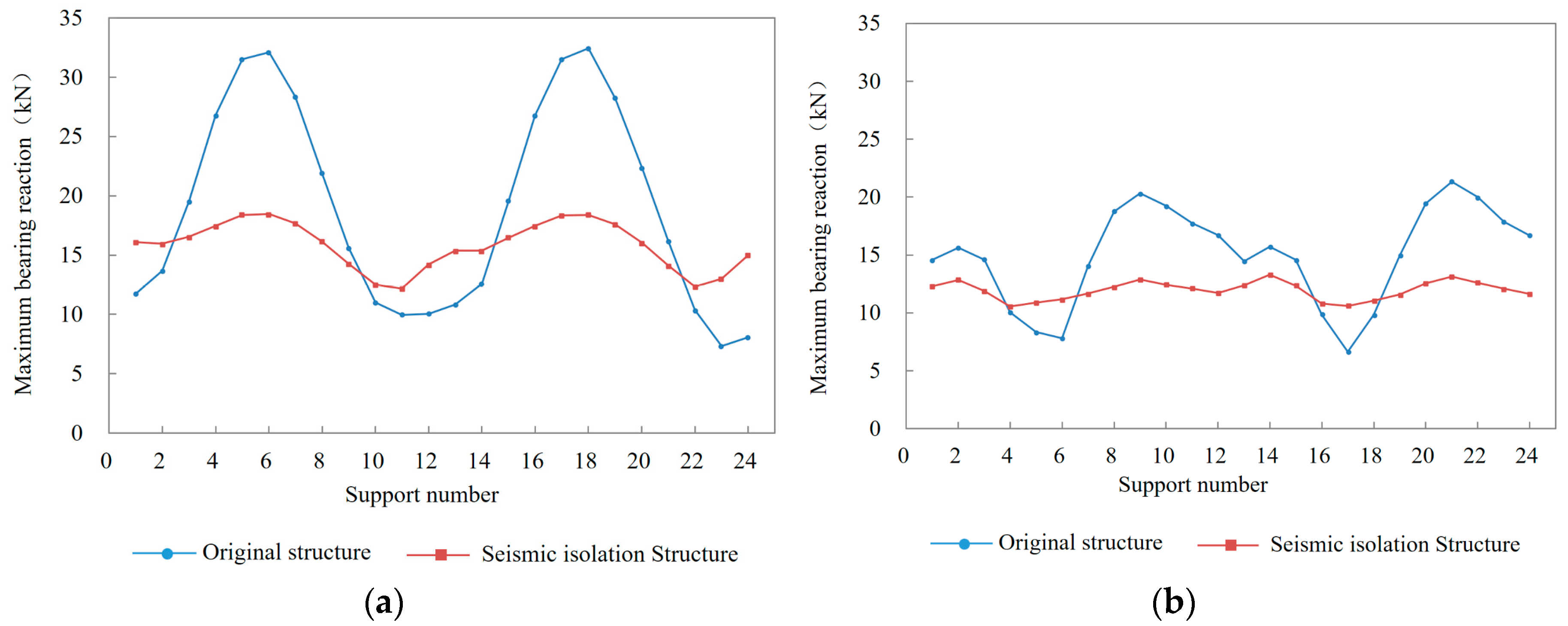
Figure 5.
Comparison of maximum inverse force distribution between original structure and seismic isolation structure under the Taft wave in frequent earthquakes, (a) in the X direction, (b) in the Y direction.
Figure 5.
Comparison of maximum inverse force distribution between original structure and seismic isolation structure under the Taft wave in frequent earthquakes, (a) in the X direction, (b) in the Y direction.

Figure 6.
Comparison of time-history curve of the reaction force of bearing No. 6 in the X direction between original structure and seismic isolation structure in frequent earthquakes, (a) under the El Centro wave, (b) under the Taft wave.
Figure 6.
Comparison of time-history curve of the reaction force of bearing No. 6 in the X direction between original structure and seismic isolation structure in frequent earthquakes, (a) under the El Centro wave, (b) under the Taft wave.

Figure 7.
Hysteretic curve in the X direction in frequent earthquakes, (a) under the El Centro wave, (b) under the Taft wave.
Figure 7.
Hysteretic curve in the X direction in frequent earthquakes, (a) under the El Centro wave, (b) under the Taft wave.
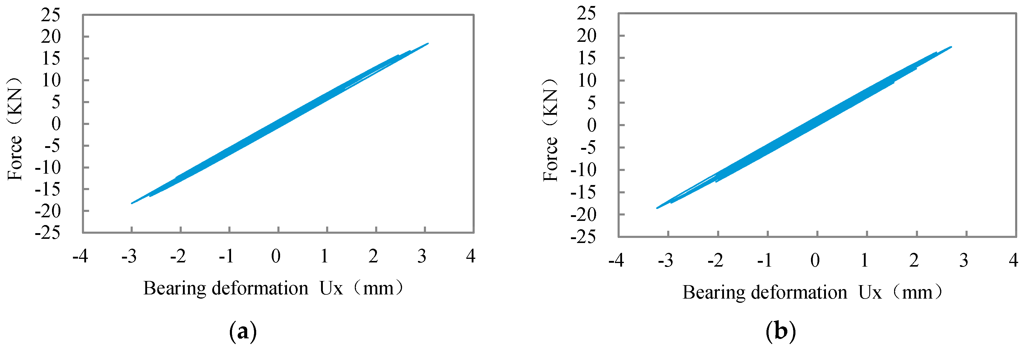
Figure 8.
Comparison of maximum inverse force distribution between original structure and seismic isolation structure under the El Centro wave in rare earthquakes, (a) in the X direction, (b) in the Y direction.
Figure 8.
Comparison of maximum inverse force distribution between original structure and seismic isolation structure under the El Centro wave in rare earthquakes, (a) in the X direction, (b) in the Y direction.
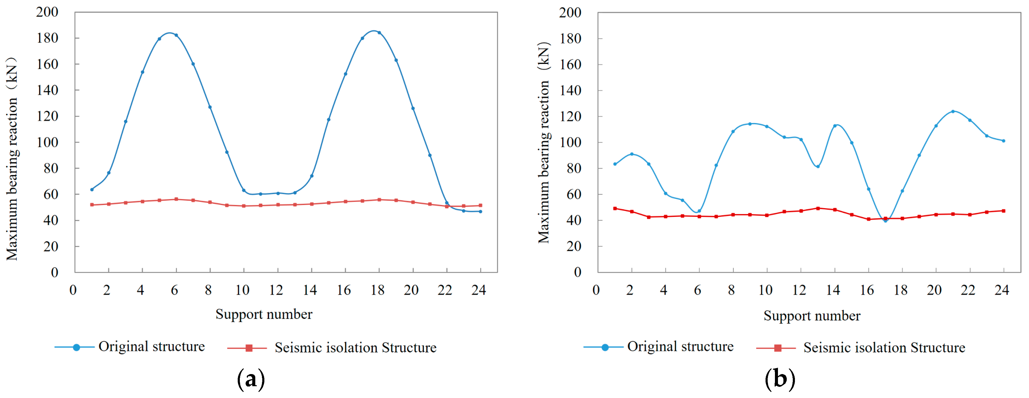
Figure 9.
Comparison of maximum inverse force distribution between original structure and seismic isolation structure under the Taft wave in rare earthquakes, (a) in the X direction, (b) in the Y direction.
Figure 9.
Comparison of maximum inverse force distribution between original structure and seismic isolation structure under the Taft wave in rare earthquakes, (a) in the X direction, (b) in the Y direction.

Figure 10.
Comparison of time-history curve of the reaction force of bearing No. 6 between original structure and seismic isolation structure in rare earthquakes, (a) under the El Centro wave, (b) under the Taft wave.
Figure 10.
Comparison of time-history curve of the reaction force of bearing No. 6 between original structure and seismic isolation structure in rare earthquakes, (a) under the El Centro wave, (b) under the Taft wave.
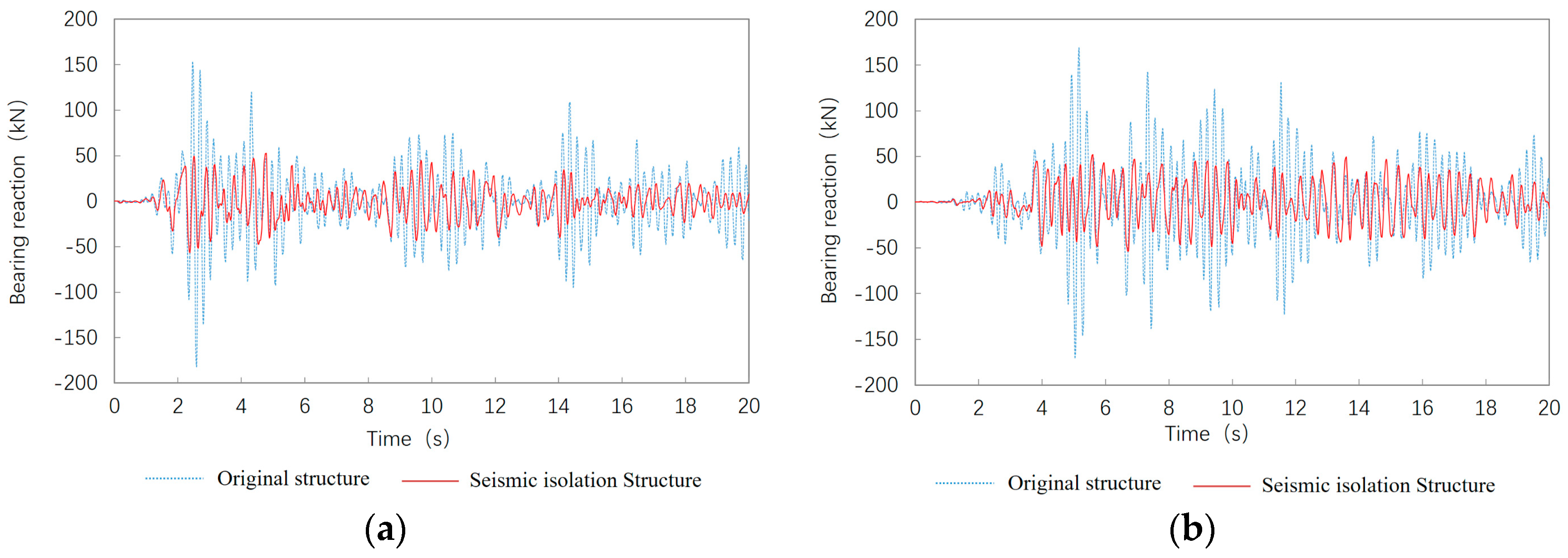
Figure 11.
Hysteretic curve in the X direction under rare earthquakes, (a) under the El Centro wave, (b) under the Taft wave.
Figure 11.
Hysteretic curve in the X direction under rare earthquakes, (a) under the El Centro wave, (b) under the Taft wave.

Figure 12.
Comparison of plastic distribution of the original upper structure under the El Centro wave, (a) original structure, (b) seismic isolation structure.
Figure 12.
Comparison of plastic distribution of the original upper structure under the El Centro wave, (a) original structure, (b) seismic isolation structure.

Figure 13.
Comparison of plastic distribution of the seismic upper structure under the Taft wave, (a) original structure, (b) seismic isolation structure.
Figure 13.
Comparison of plastic distribution of the seismic upper structure under the Taft wave, (a) original structure, (b) seismic isolation structure.


Table 1.
Mechanical performance parameters of the bearing.
| Type | Base Level Pressure (MPa) | Long-Term Load (kN) | Vertical Stiffness (kN/mm) | Horizontal Performance of 100% Deformation | ||||
|---|---|---|---|---|---|---|---|---|
| Initial Stiffness (kN/mm) | Post-Yield Stiffness (kN/mm) | Yield Force (kN) | Equivalent Stiffness (kN/mm) | Equivalent Damping (%) | ||||
| LRB600 | 6 | 1178 | 1513 | 6.27 | 0.483 | 51 | 0.878 | 23.9 |
Table 2.
The comparison of natural frequency for original and seismically-isolated structures.
| Mode Number | Natural Frequency (Hz) | Percentage Scatter | |
|---|---|---|---|
| Original Structure | Seismic Isolation Structure | ||
| 1 | 3.80 | 1.6207 | 57% |
| 2 | 3.80 | 1.6208 | 57% |
| 3 | 4.22 | 2.3588 | 44% |
| 4 | 4.22 | 3.2405 | 23% |
| 5 | 4.50 | 3.8370 | 15% |
| 6 | 4.5091 | 3.8371 | 15% |
| 7 | 4.6865 | 4.0540 | 13% |
| 8 | 4.6867 | 4.0544 | 13% |
| 9 | 4.6920 | 4.1578 | 11% |
| 10 | 4.6921 | 4.1580 | 11% |
| 11 | 4.6976 | 4.3140 | 8% |
| 12 | 4.7029 | 4.3140 | 8% |
| 13 | 4.7032 | 4.4963 | 4% |
| 14 | 4.8545 | 4.4974 | 7% |
| 15 | 4.8545 | 4.6357 | 5% |
© 2019 by the authors. Licensee MDPI, Basel, Switzerland. This article is an open access article distributed under the terms and conditions of the Creative Commons Attribution (CC BY) license (http://creativecommons.org/licenses/by/4.0/).
Share and Cite
MDPI and ACS Style
Zhai, Y.; Fu, X.; Chen, Y.; Hu, W. Study on Column-Top Seismic Isolation of Single-Layer Latticed Domes. Sustainability 2019, 11, 936. https://0-doi-org.brum.beds.ac.uk/10.3390/su11030936
AMA Style
Zhai Y, Fu X, Chen Y, Hu W. Study on Column-Top Seismic Isolation of Single-Layer Latticed Domes. Sustainability. 2019; 11(3):936. https://0-doi-org.brum.beds.ac.uk/10.3390/su11030936
Chicago/Turabian StyleZhai, Yongmei, Xuxia Fu, Yihui Chen, and Wei Hu. 2019. "Study on Column-Top Seismic Isolation of Single-Layer Latticed Domes" Sustainability 11, no. 3: 936. https://0-doi-org.brum.beds.ac.uk/10.3390/su11030936
Note that from the first issue of 2016, this journal uses article numbers instead of page numbers. See further details here.