Hybrid Simulation of Soil Station System Response to Two-Dimensional Earthquake Excitation


1
State Key Laboratory of Disaster Reduction in Civil Engineering, Tongji University, Shanghai 200092, China
2
Department of Geotechnical Engineering, Tongji University, Shanghai 200092, China
3
Department of Bridge Engineering, Tongji University, Shanghai 200092, China
*
Author to whom correspondence should be addressed.
Sustainability 2019, 11(9), 2582; https://0-doi-org.brum.beds.ac.uk/10.3390/su11092582
Submission received: 30 March 2019
/
Revised: 26 April 2019
/
Accepted: 28 April 2019
/
Published: 5 May 2019
(This article belongs to the Special Issue Resilience and Sustainability of Civil Infrastructures under Extreme Loads)
Abstract
:Soil station system seismic issues have been highly valued in recent years. In order to investigate the dynamic seismic behaviors of the intermediate column in soil station systems, a hybrid test of a soil station system was conducted. The soil station model was performed with OpenSees. Virtual hybrid simulation was fulfilled with adapter elements. A hybrid model, composed of the steel column specimen and the remainder numerical model, was assembled using the OpenFresco framework. An intermediate column was treated as the physical substructure, while the rest of the soil station system was treated as the numerical substructure in a hybrid simulation. The hybrid test results are compared with the analytical results. The data obtained from such tests show that the system can accurately reflect the mechanical properties of intermediate columns in soil station systems. A hybrid simulation would be a proper way to assess the seismic performance of a soil station system.
1. Introduction
The uninterrupted service of transportation infrastructure after an earthquake is of great importance for the immediate recovery and long-term economic sustainability of the impacted region. Subway stations and railway systems, essential components of the transportation infrastructure, are designed to provide continued function after both frequent and rare seismic events [1]. It is generally believed that the seismic performance of underground structures is superior to superstructure since underground structures are surrounded and restrained by soil and rock. However, several catastrophic earthquake events have happened in recent years such as the Kobe earthquake, Chi-Chi earthquake, and Wenchuan earthquake, and thus the seismic performance of an underground structure is of concern to many researchers [2,3,4,5,6]. Especially in 1995, the Daikai subway station suffered serious damage under the Hyogoken-Nanbu earthquake, including shear failure of the intermediate column, which had never been observed in the past. The failure positions of the intermediate column are mostly located at the base and top part of the intermediate column [7]. Moreover, a large number of cracks have caused serious damage to underground engineering facilities. Insufficient horizontal shear resistance of the intermediate column is the main reason why the Daikai station failed during the seismic event [8]. Most research has conducted dynamic analyses to study the failure mechanism of the subway station, few studies have adopted seismic testing methods. Seismic testing methods based on intermediate columns are necessary and significant ways to evaluate the seismic performance of a soil station system.
There are several seismic testing methods, including the pseudo-static test (PST), shaking table test (STT) and pseudo-dynamic (PSD) test. The PST method is to apply prescribed cyclic displacement or cyclic force history on a structure component with actuators at a low speed. The shortcoming of PST method is that the predefined load and displacement cannot reflect real seismic responses of structures [9]. In the STT method, structure specimens are fixed on a shaking table. The shaking table provides acceleration boundary conditions at the bottom of structure specimens. When it comes to performing the shaking table test on underground structures, such as tunnel or subway station specimens, there exist two main issues that are often improperly considered. The first one is that the size and payload of the tested structure is greatly limited to the size and payload of the table used. The second one is the gravity distortion effect.
The hybrid simulation (HS) testing method, initially named the pseudo-dynamic testing method, was proposed in 1969 [10]. This method combines the physical test of the nonlinear components of a structure and the numerical simulation of the remainder [11]. Without the size and payload limitation, hybrid simulation can easily enlarge the size of the specimen so that test results would not be impacted by scale factors. Hybrid simulation development trends are composed of two aspects. One aspect involves developing next-generation hybrid simulation methods that will provide more realistic structural responses, including robust numerical integration techniques [12,13,14,15] and the loading control method [16,17,18,19]. The other aspect involves providing validated general hybrid simulation procedure suitable to various projects and testing facilities to promote its awareness and broader applications, including the geographically distributed hybrid simulation, and developing a benchmark hybrid simulation [20,21,22]. Based on the experience of hybrid projects in the George E. Brown, Jr. Network for Earthquake Engineering Simulation (NEES), hybrid simulation, and especially displacement-based PSD simulation, is a viable approach to generate reliable structural seismic responses [23]. For instance, Tessari utilizes both shaking tables and dynamic actuators as an ideal experimental method to investigate soil structure interaction issues, where a massive test specimen of soil can be accommodated by the shaking table and the interactions between the soil and structure can be simulated by the actuators [24]. Hybrid simulation is a unique way to experimentally judge the seismic performance of underground structures. With the hybrid simulation test method, a reasonable full-scale model of the intermediate column in a subway station could be studied when an earthquake excitation proceeds.
A study of the dynamic responses of the intermediate column in underground structures by applying the hybrid simulation method is presented in this paper. Both virtual hybrid simulation and physical hybrid simulation are performed in this paper. A virtual hybrid simulation is conducted before the implementation of an actual hybrid test, which works as a preparatory simulation in order to check all the setting/adjustments, make sure the numerical calculator is working fine and there is no data exchange problem between numerical and physical subparts of the structure. A novel steel specimen is designed for the physical hybrid simulation. According to different study needs, the stiffness of the steel specimen could be easily changed by a simple calculation and replacement of some screws before the test. Hybrid simulation with such steel specimens allow for repetitive tests with low costs. Thus, hybrid simulation emerges as a best way to experimentally assess the performance of underground structures under earthquake excitation.
2. Theory of Hybrid Simulation
In traditional PSD testing, the dynamic equation is solved to get displacement response during test process. In Equation (1), M is the mass matrix, C is the damping matrix, is the resisting force, is the acceleration vector, velocity vector and displacement vector of numerical model, and is the input motion.
In Equation (2), is the mass matrix of whole structure, is the mass matrix of numerical substructure, is the damping matrix of numerical substructure, is the resisting force of numerical substructure, is the resisting force of experimental substructure, is the acceleration vector, velocity vector and displacement vector of numerical substructure, is the displacement vector of experimental substructure, and is the input motion [25]. As shown in Figure 1, PSD substructure testing theory is adopted as analysis method for realizing hybrid simulation of underground structures in this paper. The implementation procedures are as follows: treat structure response as initial conditions at time , measure the resisting force of experimental substructure , obtain the solution of structure response at time ; treat structure response as initial conditions at time , measure the resisting force of experimental substructure , obtain the solution of structure response at time . Such a calculation cycle should be repeated until the hybrid simulation process is over.
3. Numerical Substructure
3.1. Input Motions
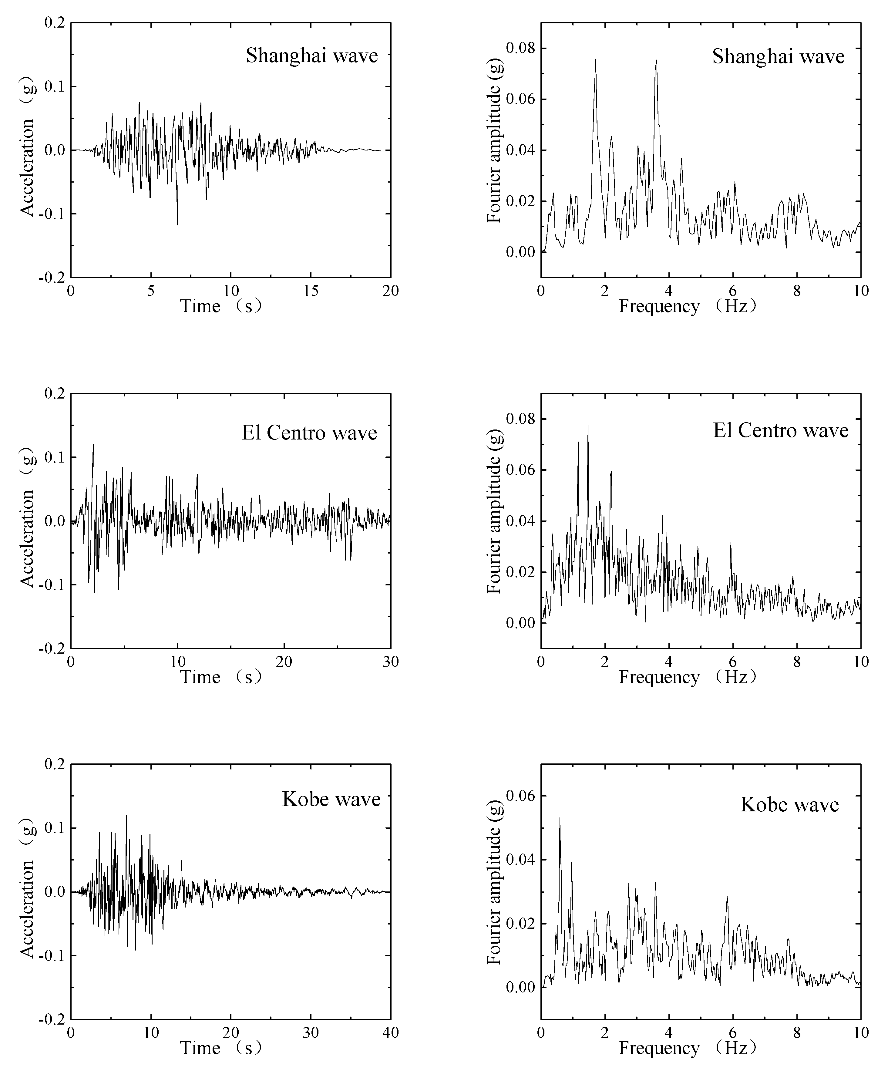
The Shanghai artificial wave, El Centro wave and Kobe wave are adopted as the input earthquake motions. Figure 2 shows the seismic acceleration time histories and spectra. It should be noted that the Shanghai artificial wave is a kind of synthetic earthquake motion developed to predict bedrock movements under the specific construction site [26]. The frequency content of the Shanghai artificial motion is mainly below 10 Hz and the dominate frequency ranges from to 1.7 to 3.6 Hz based on the results of a Fourier transform [27]. The peak base acceleration (PBA) of such three motions are scaled to 0.12 g in this paper.
It is assumed that the bedrock is rigid, the bottom of the model is fixed in such a way that no movement is allowed on the vertical and horizontal direction. Moreover, the lateral boundary is set as the equal displacement and impermeable boundary [28]. In this way, vertically polarized shear waves (SV seismic waves) can be properly considered in the seismic issue of the soil station system.
3.2. Soil Modeling
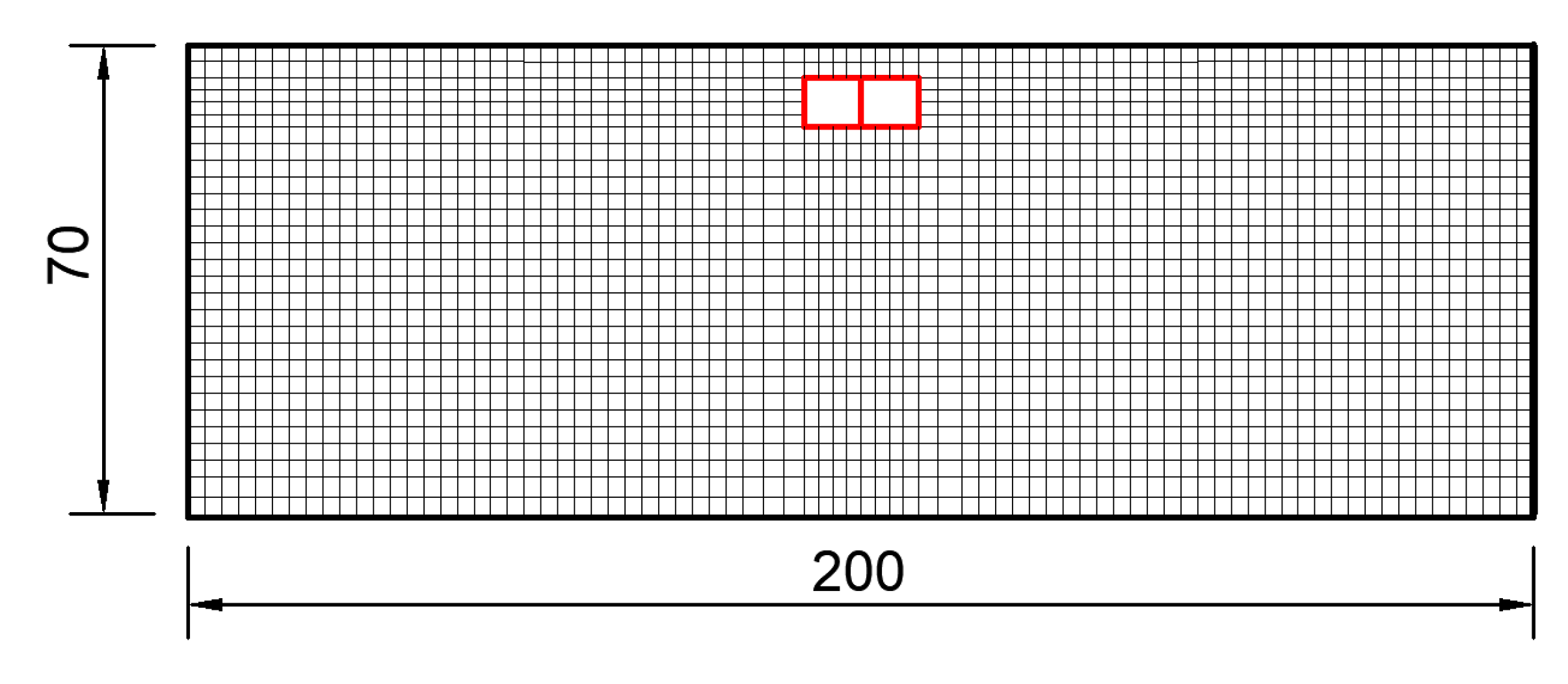
The analysis is carried out under plane strain assumptions [29]. Note that the seismic response of the soil-station system is a 3D issue, a 2D analysis model is carried out by assuming plane strain condition. Linear elastic material is adopted in the model for simulating the soil layer. In addition, the soil layer is simulated with total stress analysis. Moreover, the soil layer in finite element analysis (FEA) model is homogeneous, and the properties of soil are constant along the depth in a vertical direction. The dimension of the soil domain is 200 m long and 70 m deep (bedrock level). The soil parameters applied in the FEA model are listed in Table 1. Quad elements are employed to model the soil layer. Four-noded quad elements can be used to perform drained analysis, total stress analysis, and undrained analysis.
3.3. Structure Modeling
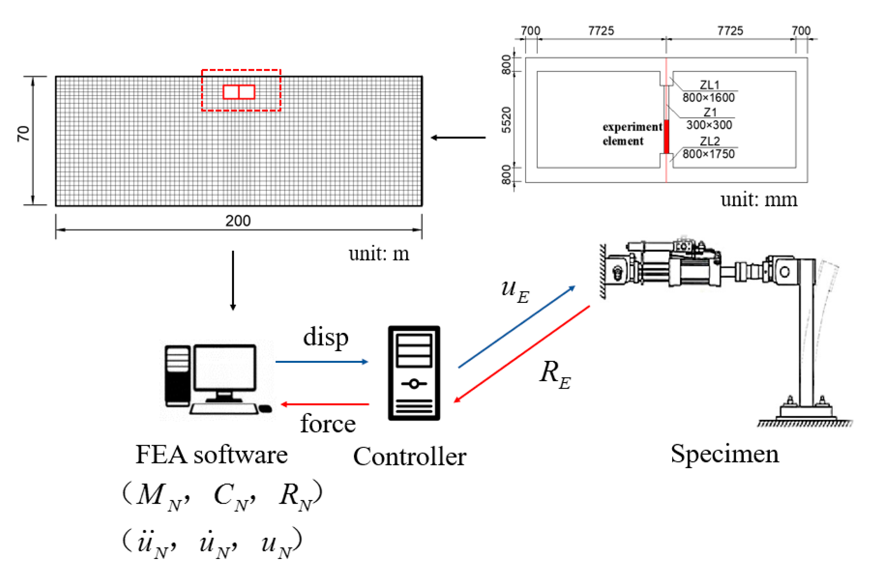
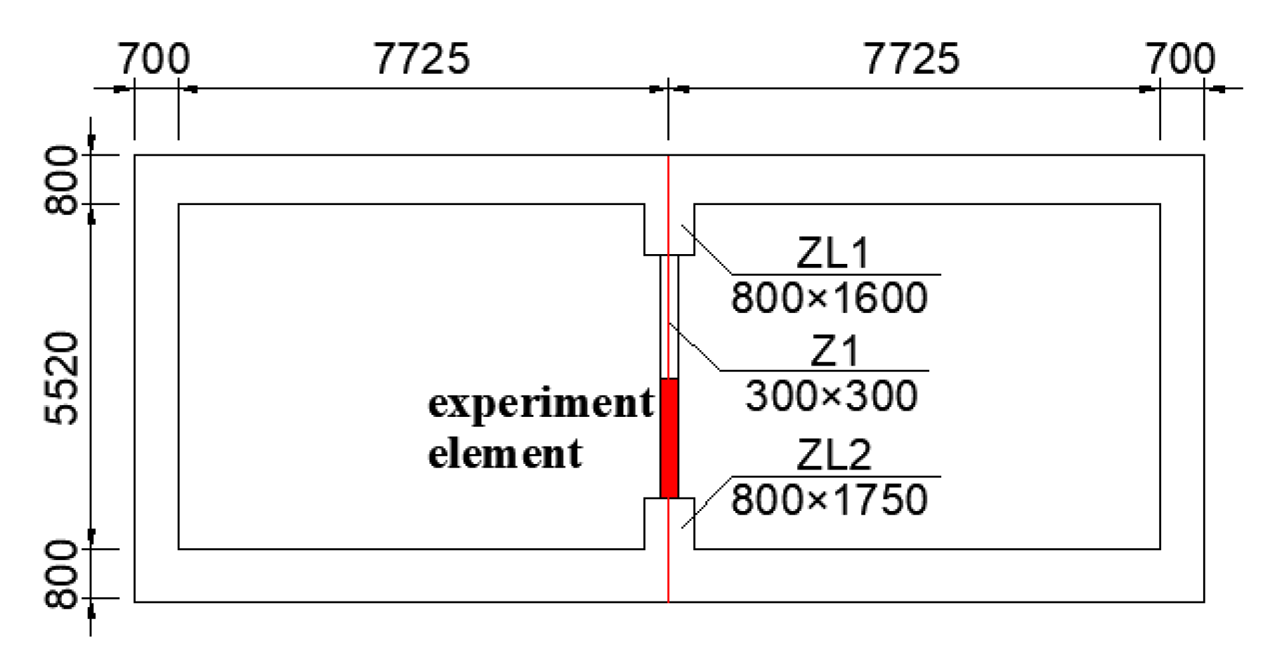
A typical rectangular subway station is adopted as the computational model. Figure 3 and Figure 4 show the FEA model in detail. The FEA model is taken sufficiently long so that lateral boundaries would not influence the seismic response of soil layer. The dimensions of the soil domain are 200 m long and 70 m deep. The rectangular subway station section is 17 m × 7.2 m, the station is embedded 4.8m deep below ground surface. It should be emphasized that the bedrock is 70 m away from the ground surface. The soil elements are 3.5 m in thickness based on the column spacing. In addition, the top slab is 0.8 m thick, the bottom slab is 0.85 m thick and the side wall is 0.7 m thick. Further, the intermediate column section is 0.3m × 0.3m.
In the FEA model, the concrete compressive strength is 39.8 MPa, and the concrete strain at maximum strength is 0.002. The concrete crushing strength is 20 MPa, and the concrete strain at crushing strength is 0.004. Nonlinear beam column elements are adopted to simulate the slabs, walls and intermediate columns. Concrete 01 material is selected in OpenSees. Such material is used for constructing a uniaxial Kent-Scott-Park concrete material object with a degraded linear unloading/reloading stiffness. No tensile strength is considered in Concrete 01 material [30].
The soil and structure are directly bonded together using the equalDOF command. This is a simplified algorithm and the slippage of soil near the structure could not be considered. In the refined analysis model, the above factors need to be considered, and the contact element can be adopted for the simulation. A one-dimensional nonlinear spring and a tangentially nonlinear spring could simulate the behaviour of the slippage of soil near the structure [31]. A section of 2 × 2 m soil elements are adopted for the reason that the soil element length should be less than approximately one-tenth to one-eighth of the wavelength associated with the maximum frequency component of the input seismic motion. For the case of a 70 m deposit excited by the Shanhai artificial wave, a target damping ratio of 5% is calculated by calibrating parameters in Equations (3)–(5). The first mode of the site and five times this frequency for and are selected as parameter for the target damping ratio [32].
4. Hybrid Simulation Procedure
4.1. Virtual Hybrid Simulation Procedure
A virtual hybrid simulation is performed based on the FEA model mentioned before. In physical hybrid simulation case, middleware platform OpenFresco provides a bridge between a standard finite element analysis program and laboratory control data-acquisition systems. In virtual hybrid simulation, one OpenSees process stands for numerical substructure, the other OpenSees process stands for experimental substructure. Adapter elements are utilized to manage communication between two OpenSees processes with OpenFresco [33,34]. This approach provides an important advantage that all of the connected codes run continuously without need to shut down and restart, hence reducing analysis time consumptions significantly. In this way, virtual hybrid simulation can be realized with two OpenSees processes connected by adapter elements on OpenFresco platform.
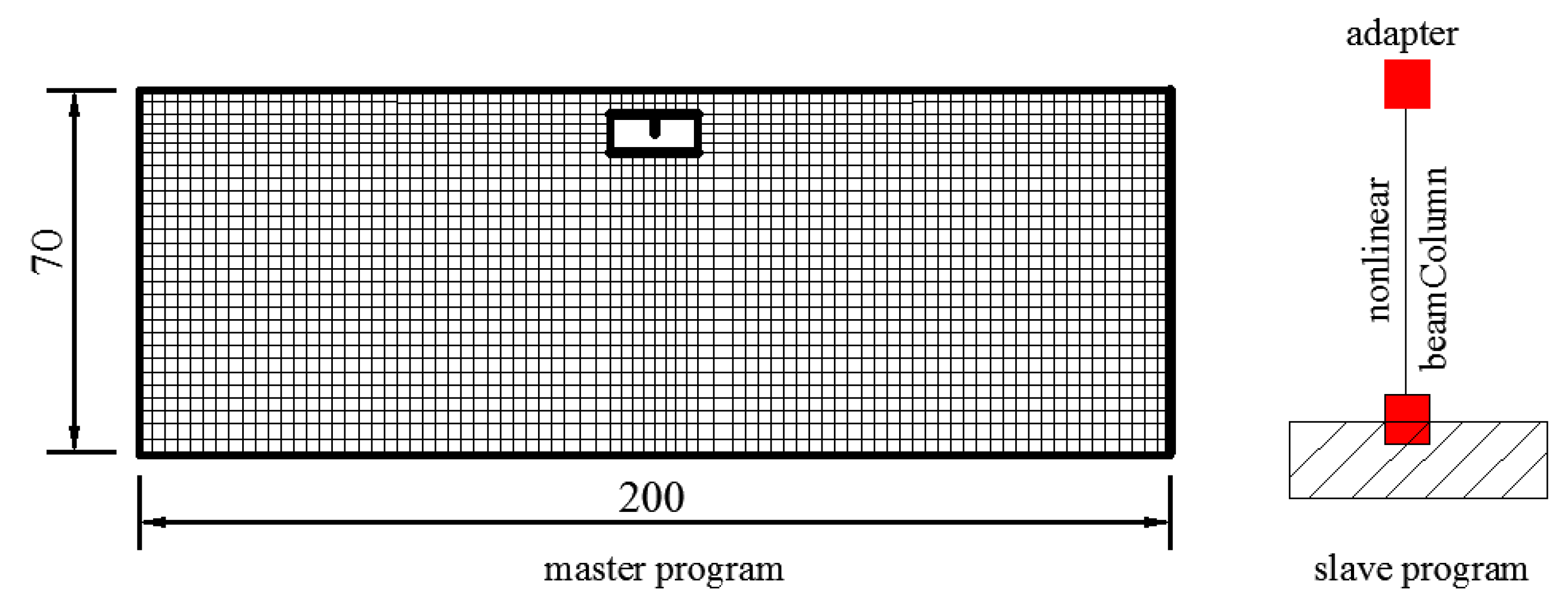
When coupling two or more finite element programs, the structure is generally divided into two parts: master and slave. The master is the main part which solves the equation of motion of the whole structure, while the slave represents different substructures and is responsible for the modelling and analysis of them [35]. As shown in Figure 5, the half intermediate column was analyzed in the slave program, the rest of the structure’s components and soil were analyzed in the master program. The adapter element, which connected the slave program and master program on the interface node, ensured that the two OpenSees shared same displacement order during virtual hybrid test process. In the slave program, the base of the column is restrained at all three degrees of freedom. The initial stiffness matrix of the column element needs to be specified. Such a matrix can be determined from geometric condition.
In the slave program, the substructure conforms to Equation (6):
where M represents the global mass matrix; represents the global resisting force vector; P represents seismic load vector; represents the global element load vector.
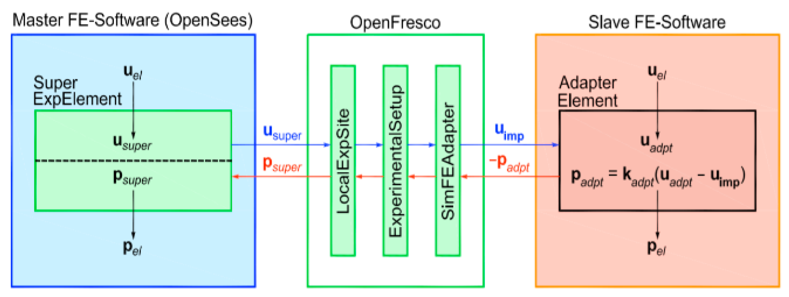
In Equation (7), represents externally applied load vector due to the imposed displacements, represents the stiffness of the adapter element, represents imposed displacements, represents nodal force vector of the adapter element, represents load vector due to deformations, represents the adapter element deformations. According to Equation (7), the element force of the adapter element is composed of two parts, one part is from the nodal force caused by the imposed displacement from the master program, and the other part is from the nodal force caused by the deformation of the adapter element itself. When a calculation step begins, the displacement order is transmitted to the slave program from the master program. When a calculation step finishes in the slave program, unbalanced force feedback is transmitted to the main program. The flow chart of data interaction between master program and slave program is shown in Figure 6. When the first analysis step begins, target displacement is calculated by the master program. It then sends these displacements using a TCP/IP socket to the OpenFresco simulation application server.
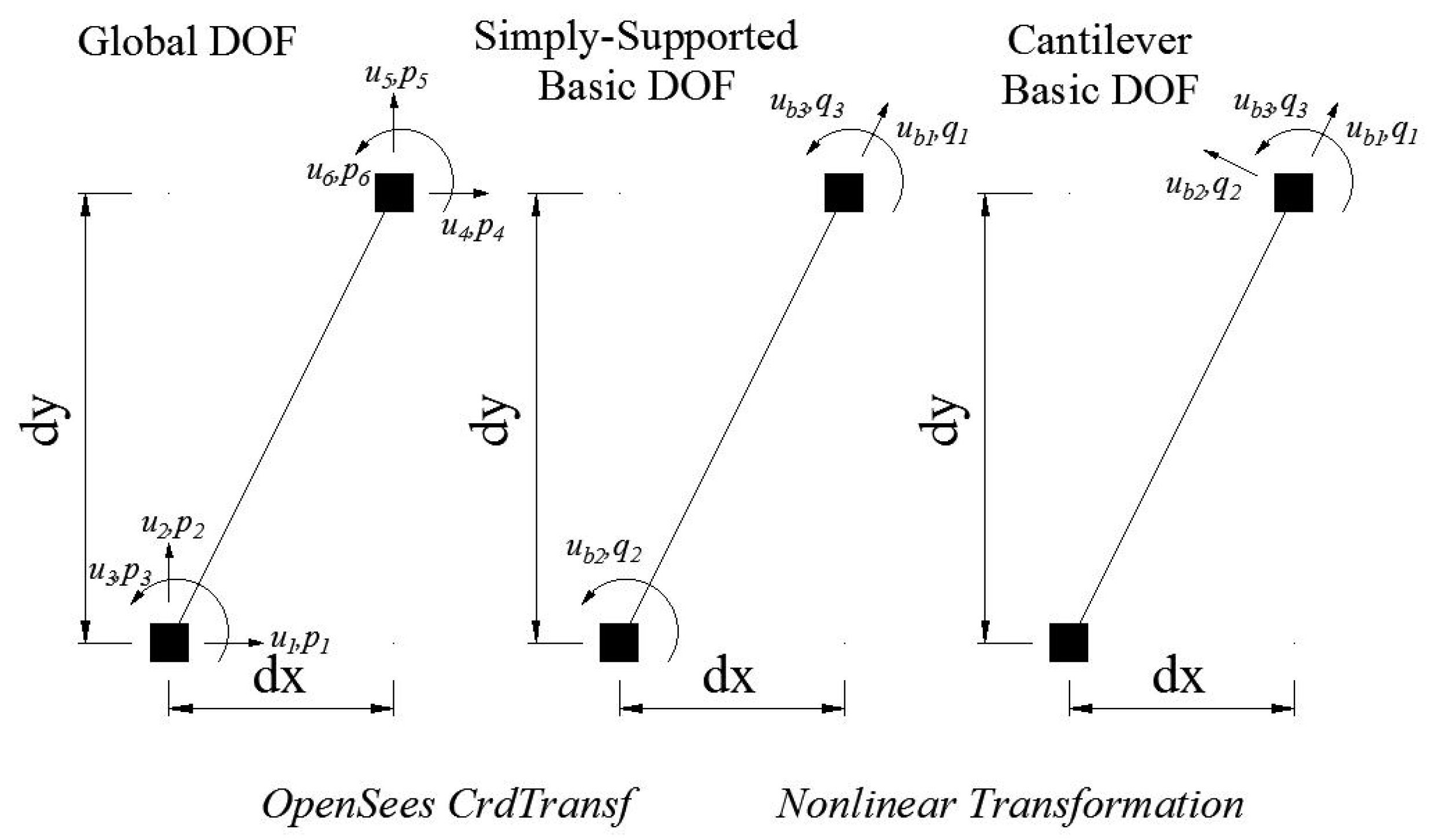
On OpenFresco platform, the experimental site module and the experimental setup module are responsible for storing, transmitting and converting displacement signals and force signals. The displacement order is transformed on OpenFresco platform by setting related parameters of experimental site module and experimental setup module. The experiment beam column element is presented in this case. Degrees of freedom (DOF) transformation for the experiment beam column element is shown in Figure 7. The adapter element then combines the received displacements with its own element displacements . Once the equilibrium solution process of the slave program has converged, the negative of the element force vector is returned to the SimFEAdapter experimental control object across the TCP/IP socket. Finally, the element force is transmitted to the master program, which is then capable to determine the new trial displacements and proceed to the next time step.
It should be emphasized that the integration methods of the finite element calculation should be adapted to each other in the master program and the slave program. In this case, the static integrator is applied in the slave program for the reason that the influence of inertial force and damping is not considered in the slave program. The Hilber-Hughes-Taylor integration method is applied in the master program. In order that the command displacement at the interface point is consistent with the top point displacement of column in slave program, it should be ensured that the stiffness of the adapter element is much larger than the lateral stiffness of the center column in slave program. In this case, the stiffness of the adapter element is selected as 2500 kN/mm.
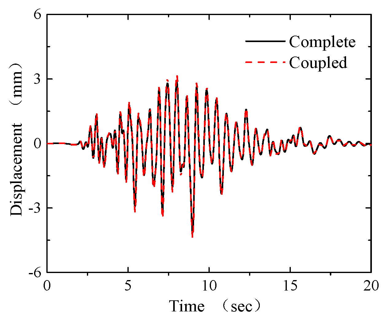
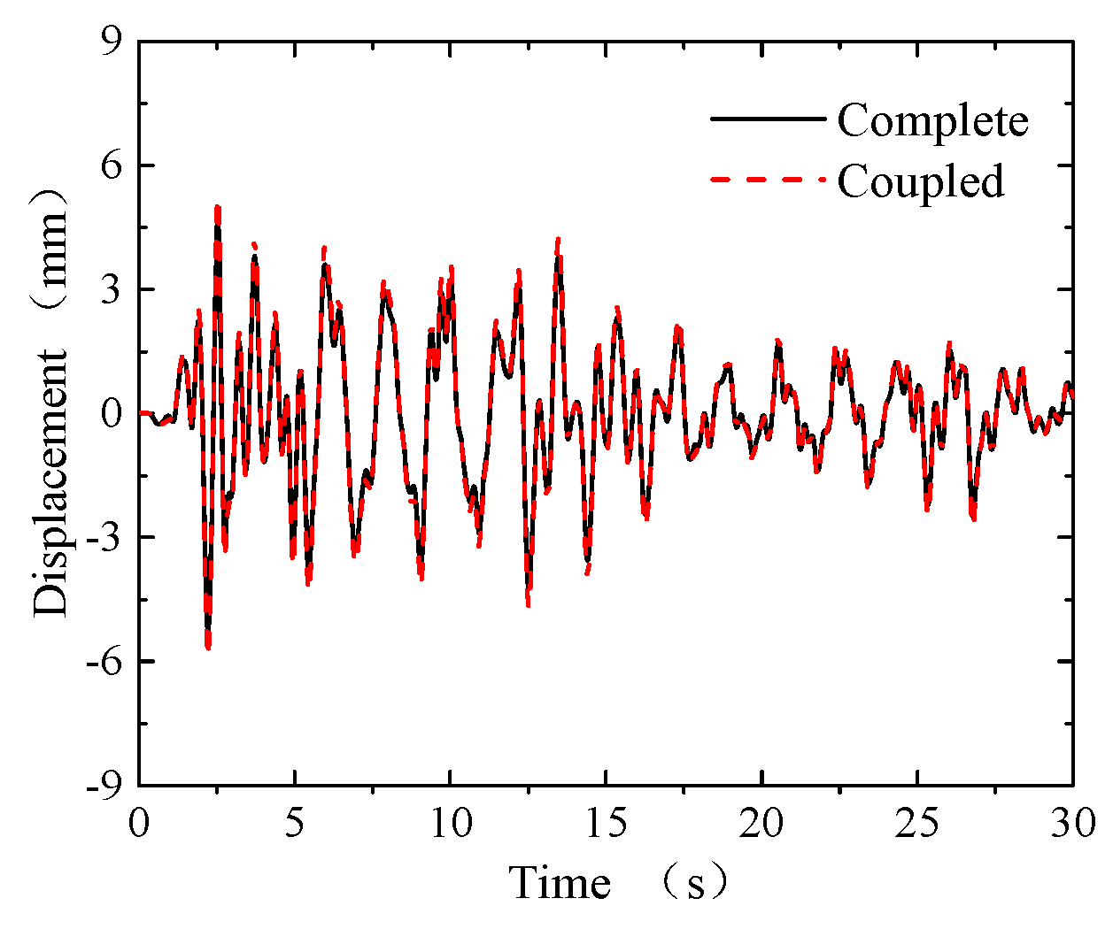
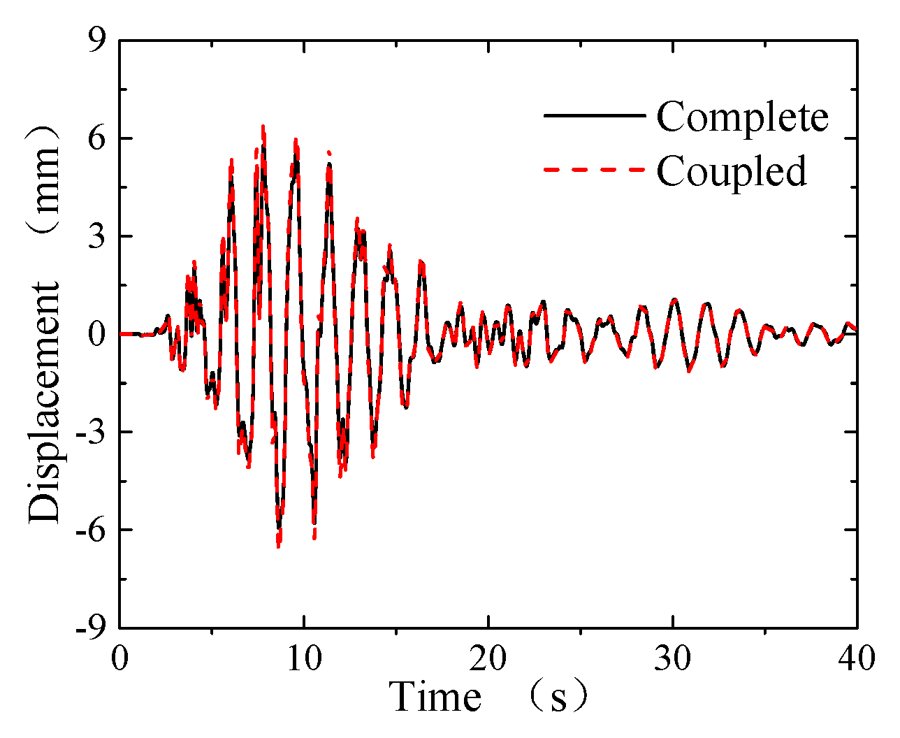
In order to verify the accuracy of the virtual hybrid test, a numerical model with the same material parameters and geometric parameters is established on OpenSees platform. The drift responses of the intermediate column in the soil station system are selected as a calibration index to verify the accuracy of the virtual hybrid test. As shown in Figure 8, Figure 9 and Figure 10, The drift responses of the virtual hybrid test (labeled as “Coupled”) and the complete numerical model (labeled as “Complete”) match well during the whole seismic process, which illustrates that the adapter elements work well during virtual hybrid simulation process.
As shown in Figure 8, peak drift in complete numerical model is −4.14 mm and peak drift in virtual hybrid simulation is −4.40 mm when the Shanghai wave is applied as input motion. A complete numerical response could be regarded as standard solution, the test error of virtual hybrid simulation is 6.4%. As shown in Figure 9, peak drift in complete numerical model is −5.30 mm and peak drift in virtual hybrid simulation is −5.69 mm when El Centro wave is applied as input motion. The test error is 7.3%. As shown in Figure 10, peak drift in complete numerical model is −5.94 mm and peak drift in virtual hybrid simulation is –6.40 mm when Kobe wave is applied as input motion. The test error is 7.8%.
In short, the virtual hybrid test process is a feasible hybrid simulation method. Two OpenSees programs run simultaneously with the adapter elements. The virtual hybrid test provides a theoretical basis for the physical hybrid test and verifies the feasibility of the FEA model.
4.2. Physical Hybrid Simulation Procedure
An intermediate column in the subway station is adopted as an experimental physical model, while the remainder of the subway station and geotechnical medium is classified as an analytical numerical model. In the experimental physical model, horizontal force is applied on the top of intermediate column by actuator in order to consider the horizontal degree of freedom. The bottom of the intermediate column is fixed to a strong floor to satisfy the boundary conditions in the analytical model. Experimental element, experimental site, experimental setup and experimental control should be defined to connect the experimental physical model and the analytical model through Openfresco. The purpose of OpenFresco middleware is to mediate the transactions between the computational driver and the physical transfer system. With a computational driver, the physical transfer system and middleware hybrid simulation framework, the hybrid simulation system is established.
The MTS-CSI control method is adopted as an experimental control method with the MTS loading system. MTS-CSI defines a control point that manages the displacement command of the test interface node at a specified degree of freedom. Moreover, this point can feed back the displacement and load responses of the interface node from experiment substructure. In such a hybrid test, the control point is selected as the inflection point of the intermediate column element. A horizontal actuator is connected with steel specimen during the loading process. In this case, the specimen was loaded with one actuator in horizontal direction. The signal of experiment substructure is converted by defining experimental setup setting in OpenFresco. The numerical substructure and the experimental substructure are both in the same laboratory. The communication is carried out in the local area network. The type of hybrid test is a local hybrid test. In OpenSees FEA model, nonlinear beam column elements are selected to simulate the seismic behaviors of intermediate column, side wall, station roof and station floor. On the OpenFresco platform, an experiment beam column element with initial stiffness matrix is adopted to represent the steel specimen in hybrid test. Since the numerical model is a 2D analytical model, the experiment element is also a 2D experimental beam column element. The experimental beam column element has two end nodes, each of which has three degrees of freedom in the axial, tangential, and rotational directions. As shown in Equation (8), the initial stiffness matrix of the experiment element can be obtained by theoretical calculation. According to the geometric information and material properties of the hybrid test specimen, the initial parameters of the experiment element are calculated. In this way, the experiment beam column element is defined in OpenFresco.
5. Experimental Setup and Test Program
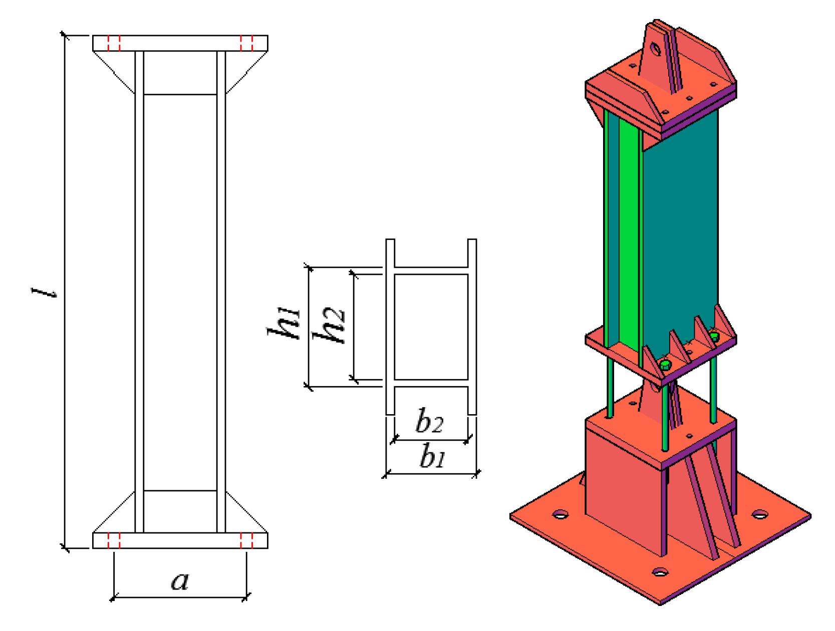
The hybrid simulation system is composed of the FEA platform OpenSees, middleware platform OpenFresco and the MTS loading system. The physical hybrid simulation was carried out in the multi-functional shaking tables lab of Tongji University. OpenFresco built a bridge between the numerical substructure and experiment substructure. Data communication and control coordination were performed on the OpenFresco platform. In addition, in order to investigate the experimental error of the hybrid simulation process, the corresponding FEA model of the soil station system was carried out by OpenSees software for each working condition. The solution of the numerical model could be regarded as a target solution for the corresponding hybrid simulation process. In the physical hybrid test, the actuator is fixed at the top of the column specimen to simulate the horizontal displacement under earthquake excitation. The top point of column specimen is the interface between numerical substructure and physical substructure. As shown in Figure 11, the top of the column and the bottom of the column are hinged. A special design is adopted for the bottom part of the column specimen. Four screws are installed to connect steel column specimen and bottom base. The bending stiffness of steel column specimen could be changed by replacing the screws at the column foot. In this way, the bending stiffness could be specified according to the test needs. Since the bending stiffness of the column itself is much larger than that of the screws, the failure mode of such tests would be the bucking failure of screws. Such an experiment could be easily repeated by replacing screws so that theupper column specimen would not be damaged during test process. In the seismic event of soil station system, numerical results demonstrated that the collapse of the structure was caused by the poor ductility of the intermediate columns. The intermediate column is the key component of seismic design in underground structures. Therefore, a cantilevered steel column is designed for hybrid simulation. Furthermore, the cantilever steel column represents the lower half of the intermediate column of the station. The lateral stiffness of steel column specimen can be obtained from Equation (9).
where is flexibility coefficient; is column height; is column elastic modulus; is moment of inertia; is rotation stiffness; is outer surface width; is outer surface height; is inner surface width; is inner surface height; is screw diameter; is screw space; is screw elastic modulus; is screw length.
The cantilever steel column specimen is the physical substructure of the soil station system hybrid test system, and the remaining parts of the FEA model are treated as numerical substructure. After each integration step, the numerical substructure in the soil station system calculates the displacement response at the control point, horizontal load is applied to physical substructure by loading system according to displacement order. After the displacement command is applied to the physical substructure, the restoring force signal of steel column specimen is measured by the actuator and transmitted back to the data interaction system. On the OpenFresco platform, restoring force response order and displacement response order would be exchanged at each integration step. Such orders would be converted according to geometric transformations by setting experiment site, experiment element, experiment control and experiment actuator. After the numerical substructure obtains a restoring force signal from the physical substructure, such a signal would be transmitted back to dynamic equations to complete the calculation of the next time step in the numerical substructure. The displacement command for next time step would be calculated on basis of restoring force signal accepted. Such a cycle would be repeated until the test is over. Based on the results of the virtual hybrid test procedure and the analytical model, the physical substructure specimens were designed according to the principle of equivalent lateral stiffness. The lateral stiffness of the test substructure was adjusted by changing the screws which were installed at the bottom of steel column. In this case, four vertical screws with a diameter of 15 mm were placed at the bottom of the column, and the lateral stiffness of the physical substructure was 2.10 kN/mm measured by loading system. The lateral stiffness of the intermediate column element is extracted in OpenSees, which is 2.06 kN/mm correspondingly. During the hybrid simulation process, a stiffness matrix of the physical substructure is updated according to the feedback force signal.
6. Overview of Experimental Observation
6.1. Phase 1: Pseudo-Static Tests
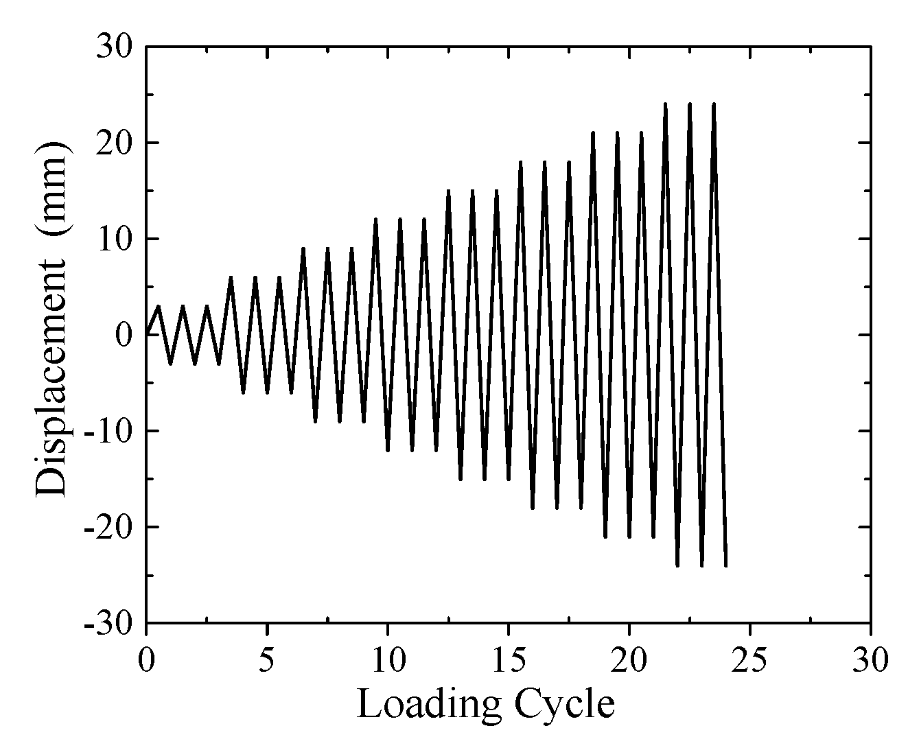
In order to investigate the plastic behaviors and energy dissipation capacity of a steel specimen during a real seismic event, a pseudo-static test of the steel specimen was conducted before a hybrid simulation test. The bottom of the column was fixed on the strong floor and the column end was connected to a hydraulic actuator which permitted free horizontal degree of freedom of the column. Each test specimen was subjected to a pseudo-static reversed cyclic simulated earthquake loading as shown in Figure 12. In order to investigate the plastic behaviors and energy dissipation capacity of steel specimen during a real seismic event, the loading sequence adopted in this testing program followed the typical pseudo-static test sequence. In the current study, it is believed that the probable seismic resistance of a sub-component evaluated following the simple testing sequence is able to provide a satisfactory behavior during a real seismic event [34]. The horizontal cyclic loading applied to the specimens throughout the test was displacement controlled. The horizontal loading was applied to the top of the column using a 500kN capacity hydraulic actuator. No axial load was applied to the test specimens.
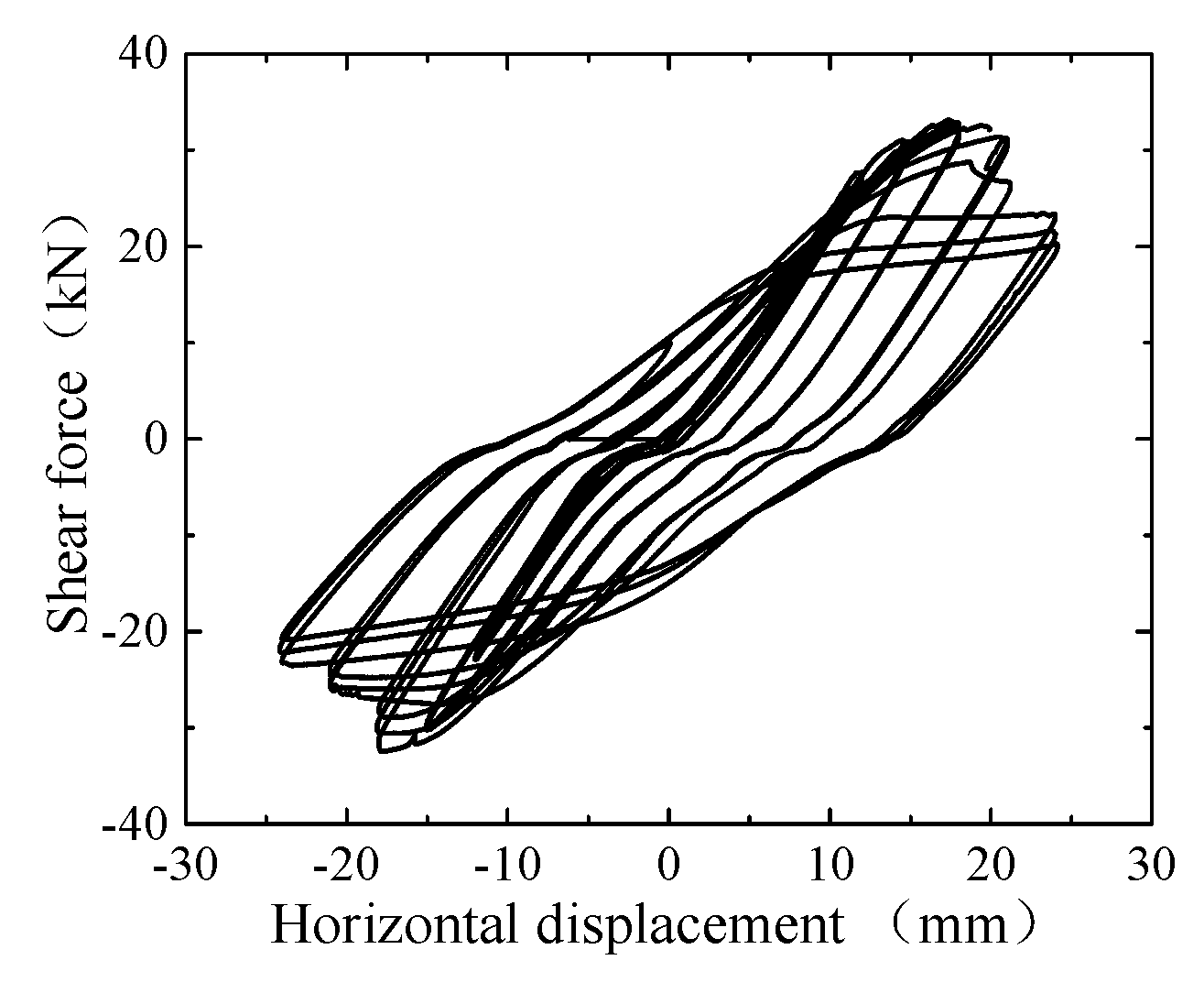
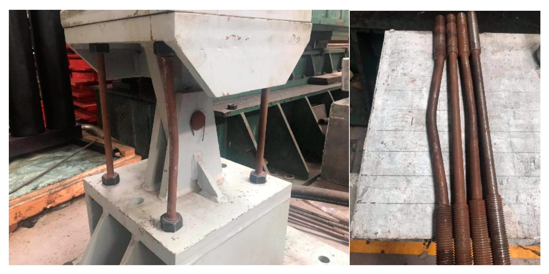
As shown in Figure 13, shear force versus horizontal displacement relationship illustrates loading capacity and mechanical behaviors of test specimen. Steel column specimen reached the yield load (26.5 kN) when horizontal displacement reached 13.2 mm. Steel column specimen reached the ultimate load (32.3 kN) when horizontal displacement reached 17.4 mm. The hysteretic response was mainly characterized by the stiffness degradation and the strength degradation. As shown in Figure 14, the most important type of failure mode in the bolt rod area was mainly screw yielding failure.
6.2. Phase 2: Hybrid Simulation Tests
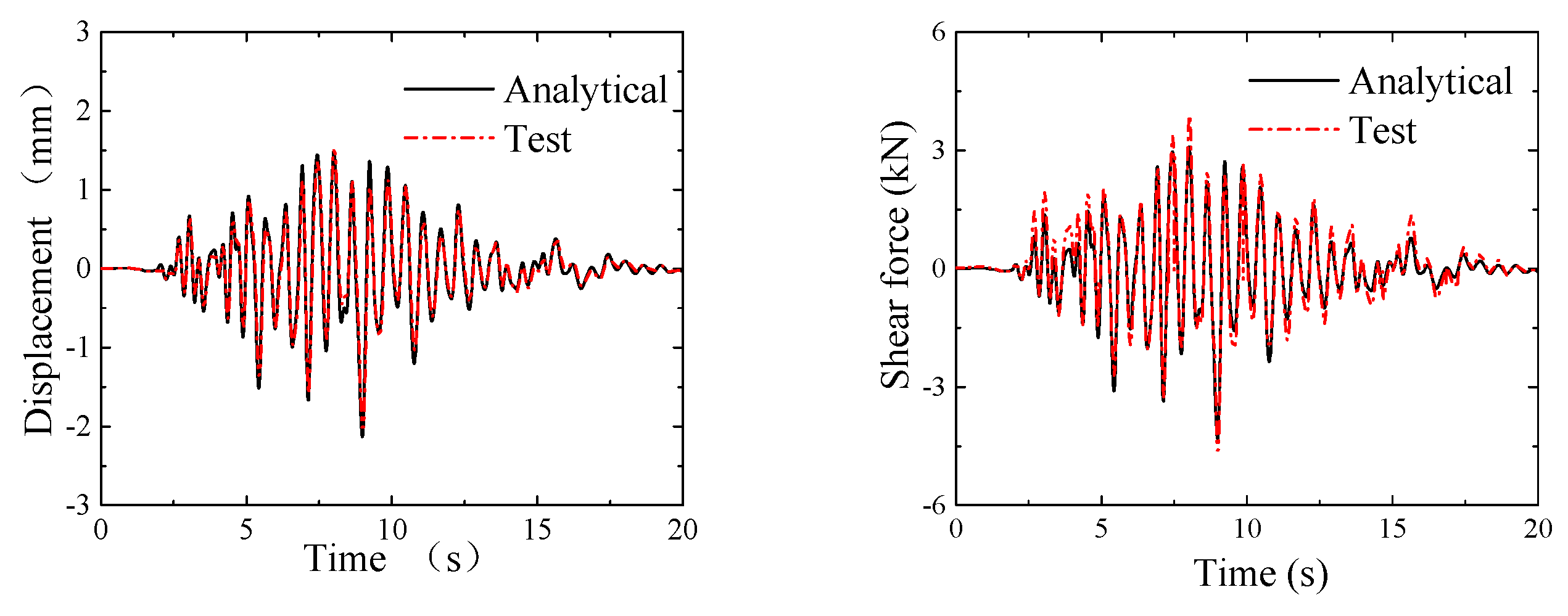
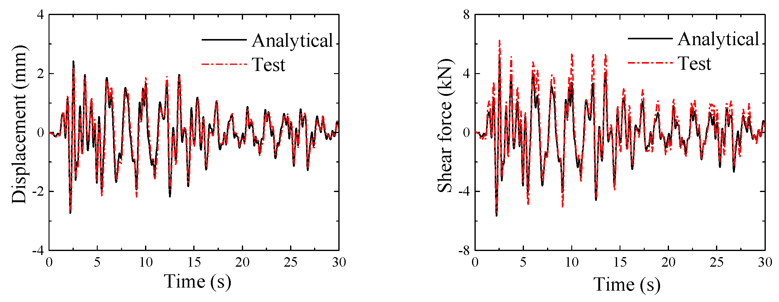
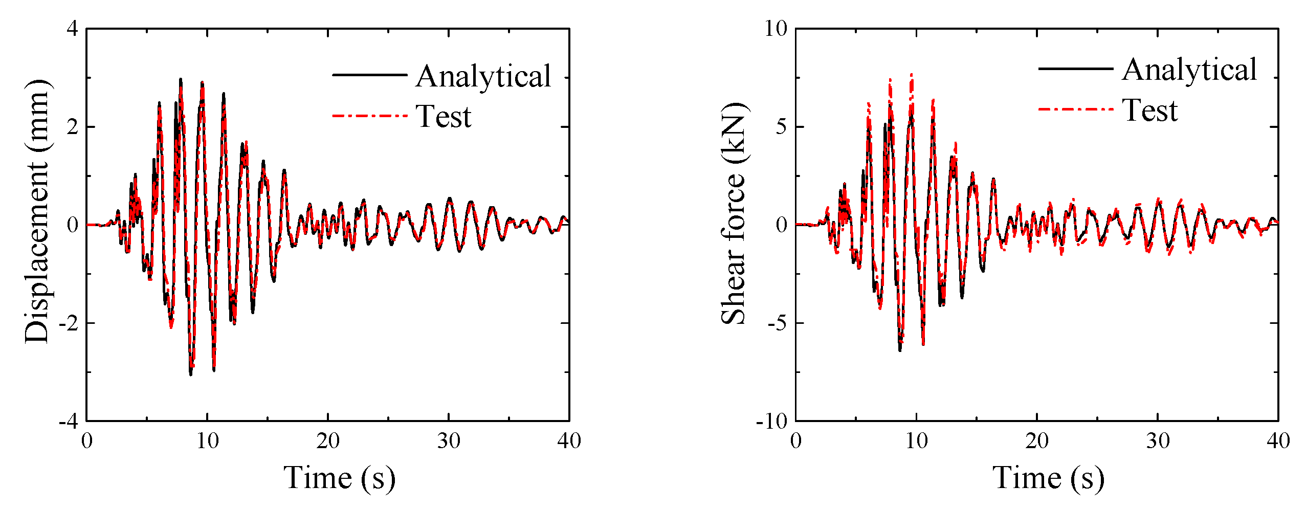
With the previously mentioned method, a series of hybrid simulation tests were carried out on the test model under the following base accelerations: Shanghai artificial wave, El Centro wave and Kobe wave. The peak acceleration of three waves is 0.12g. Figure 15 shows lateral displacement and shear force time histories of control point in Shanghai artificial wave case. Figure 16 shows the lateral displacement and shear force time histories of control point in the El Centro wave case. Figure 17 shows lateral displacement and shear force time histories of control point in Kobe wave case. It should be emphasized that the shear force test results in the three working conditions were larger than the analytical results for the reason that the actual stiffness of the intermediate column specimen was greater than the theoretical stiffness in the analytical model. Based on the pseudo-static test results above, it should be noted that the specimen stayed in elastic stage during the three working conditions. Overall, such a specimen applied in hybrid simulation tests was reasonable in this case.
In order to calibrate the accuracy of the hybrid test, shear force and horizontal displacement response of the numerical model were plotted in the same figure. It can be seen that the numerical simulation results matched well with the hybrid simulation test results under earthquake excitation. Thus, the feasibility and accuracy of the physical hybrid simulation test could be verified. The good correspondence between the hybrid simulation and analytically obtained response data validated the analytical model of soil station system. The comparison suggested a good agreement, which indicated the proposed hybrid simulation composed by OpenSees, OpenFresco and MTS performed well in the soil station system hybrid simulation.
7. Conclusions
A study of the two-dimensional seismic response of a soil station system by applying hybrid simulation is reported in this paper. Firstly, the soil station system FEA model is developed for the subsequent hybrid simulation process. The virtual hybrid simulation method is implemented on bases of OpenSees and OpenFresco with an adapter element. The adapter element is then used to connect two FEA programs to implement a virtual hybrid test process. The virtual hybrid simulation provides a theoretical basis for the following physical hybrid test. Moreover, the virtual hybrid simulation also helps to verify the feasibility of a developed numerical substructure in the hybrid test. According to the principle of equivalent lateral stiffness, a novel steel specimen is designed to physically model the intermediate column in this paper. The hybrid test results are compared with the analytical results, to validate the effectiveness and accuracy of the proposed hybrid simulation method. The following conclusions can be drawn:
- The implementation of a virtual hybrid simulation with two OpenSees processes based on adapter elements is a good way to verify the effectiveness and robustness of the hybrid simulation system. The results of the virtual hybrid simulation are in agreement with the numerical simulation results, which verify the correctness of the established hybrid test system.
- The variable stiffness steel column specimens applied in the hybrid test were designed according to the corresponding stiffness in the numerical substructure. The lateral stiffness of the steel specimen is changed by replacing the screws. The stiffness could be obtained from design parameters before testing.
- The mechanical behavior of the intermediate column under earthquake excitation could be reproduced by the proposed hybrid simulation system composed of OpenSees, OpenFresco, MTS-CSI and loading system.
Author Contributions
Conceptualization, C.-Y.Y. and Y.Y.; Data curation, Y.-C.M.; Investigation, X.-S.C.; Methodology, C.-Y.Y. and X.-S.C.; Software, X.-S.C. and Y.-C.M.; Supervision, Y.Y.; Writing—original draft, X.-S.C.; Writing—review editing, C.-Y.Y. and Y.Y.
Funding
This research was funded by Shanghai Committee of Science and Technology (16DZ1200302).
Conflicts of Interest
The authors declare no conflict of interest.
References
- Terzic, V.; Stojadinovic, B. Hybrid Simulation of Bridge Response to Three-Dimensional Earthquake Excitation Followed by Truck Load. Struct. Eng. 2014, 140, 1–11. [Google Scholar] [CrossRef]
- Iida, H.; Hiroto, T.; Yoshida, N. Damage to Daikai subway station. Spec. Issue Soils Found. 1996, 1, 283–300. [Google Scholar] [CrossRef]
- Lu, C.; Hwang, J. Nonlinear collapse simulation of Daikai Subway in the 1995 Kobe earthquake. Tunn. Undergr. Space Technol. 2019, 87, 78–90. [Google Scholar] [CrossRef]
- Cilingir, U.; Madabhushi, S.P.G. A model study on the effects of input motion on the seismic behavior of tunnels. Soil Dyn. Earthq. Eng. 2011, 31, 452–462. [Google Scholar] [CrossRef]
- Zhuang, H.; Hu, Z.; Wang, X. Seismic responses of a large underground structure in liquefied soils by FEM numerical modelling. Bull. Earthq. Eng. 2015, 13, 3645–3668. [Google Scholar] [CrossRef]
- Tsinidis, G. Response characteristics of rectangular tunnels in soft soil subjected to transversal ground shaking. Tunn. Undergr. Space Technol. 2017, 62, 1–22. [Google Scholar] [CrossRef]
- Ma, C.; Lu, D.; Du, X. Seismic performance upgrading for underground structures by introducing sliding isolation bearings. Tunn. Undergr. Space Technol. 2018, 74, 1–9. [Google Scholar] [CrossRef]
- Huo, H.; Bobet, A.; Fernández, G. Load Transfer Mechanisms between Underground Structure and Surrounding Ground: Evaluation of the Failure of the Daikai Station. J. Geotech. Geoenviron. Eng. 2005, 131, 1522–1533. [Google Scholar] [CrossRef]
- Williams, M.S.; Blakeborough, A. Laboratory Testing of Structures under Dynamic Loads: An Introductory Review. Philos. Trans. Math. Phys. Eng. Sci. 2001, 359, 1651–1669. [Google Scholar] [CrossRef]
- Hakuno, M.; Shidawara, M.; Hara, T. Dynamic Destructive Test of a Cantilever Beam Controlled by an Analog-computer. Proc. Jpn. Soc. Civ. Eng. 1969, 1969, 1–9. [Google Scholar] [CrossRef]
- Chen, Z.; Wang, H.; Wang, H. Application of the Hybrid Simulation Method for the Full-Scale Precast Reinforced Concrete Shear Wall Structure. Appl. Sci. 2018, 8, 252. [Google Scholar] [CrossRef]
- Phillips, B.M.; Spencer, B.F. Model-Based Feedforward-Feedback Actuator Control for Real-Time Hybrid Simulation. J. Struct. Eng. 2013, 139, 1205–1214. [Google Scholar] [CrossRef]
- Chen, C.; Ricles, J.M.; Marullo, T.M. Real-time hybrid testing using the unconditionally stable explicit cr integration algorithm. Earthq. Eng. Struct. Dyn. 2010, 38, 23–44. [Google Scholar] [CrossRef]
- Kolay, C.; Ricles, J.M.; Marullo, T.M. Implementation and application of the unconditionally stable explicit parametrically dissipative KR-method for real-time hybrid simulation. Earthq. Eng. Struct. Dyn. 2015, 44, 735–755. [Google Scholar] [CrossRef]
- Kolay, C.; Ricles, J.M. Force-Based Frame Element Implementation for Real-Time Hybrid Simulation Using Explicit Direct Integration Algorithms. Struct. Eng. 2018, 144. [Google Scholar] [CrossRef]
- Pan, P.; Nakashima, M.; Tomofuji, H. Online test using displacement-force mixed control. Earthq. Eng. Struct. Dyn. 2005, 34, 869–888. [Google Scholar] [CrossRef]
- Günay, S.; Mosalam, K.M. Enhancement of real-time hybrid simulation on a shaking table configuration with implementation of an advanced control method. Earthq. Eng. Struct. Dyn. 2015, 44, 657–675. [Google Scholar] [CrossRef]
- Yang, T.Y.; Tung, D.P.; Li, Y. Theory and implementation of switch-based hybrid simulation technology for earthquake engineering applications. Earthq. Eng. Struct. Dyn. 2017, 46, 2603–2617. [Google Scholar] [CrossRef]
- Wu, B.; Ning, X.; Xu, G. Online numerical simulation: A hybrid simulation method for in complete boundary conditions. Earthq. Eng. Struct. Dyn. 2018, 47, 889–905. [Google Scholar] [CrossRef]
- Spencer, B.F.; Carrion, J.E.; Phillips, B.M. Real-time hybrid testing of semi-actively controlled structure with MR damper. In Proceedings of the Second International Conference on Advances in Experimental Structural Engineering, St. Louis, MO, USA, 10–12 June 2009. [Google Scholar]
- Kim, S.; Christenson, R.; Phillips, B.; Spencer, B.F. Geographically distributed real-time hybrid simulation of MR dampers for seismic hazard mitigation. In Proceedings of the 20th Analysis and Computation Specialty Conference, Chicago, IL, USA, 29–31 March 2012; ASCE: Reston, VA, USA, 2012. [Google Scholar]
- Li, X.; Ozdagli, A.I.; Dyke, S. Development and Verification of Distributed Real-Time Hybrid Simulation Methods. Comput. Civ. Eng. 2017, 31. [Google Scholar] [CrossRef]
- Shao, X.; Griffith, C. An overview of hybrid simulation implementations in NEES projects. Eng. Struct. 2013, 56, 1439–1451. [Google Scholar] [CrossRef]
- Stefanaki, A.; Sivaselvan, M.V.; Tessari, A. Soil-foundation-structure interaction using hybrid simulation. In Proceedings of the International Conference on Structural Mechanics in Reactor Technology, Manchester, UK, 10–14 August 2015. [Google Scholar]
- Mahin, S.A.; Shing, P.B. Pseudodynamic Method for Seismic Testing. J. Struct. Eng. 1985, 111, 1482–1503. [Google Scholar] [CrossRef]
- Shanghai Tunnel Engineering Rail Transit Design Research Institute. Preliminary Design of Shanghai Riverine Tunnel; Book 1, General Specification; Shanghai Tunnel Engineering Rail Transit Design Research Institute: Shanghai, China, 2013. (In Chinese) [Google Scholar]
- Tao, D.; Lin, J.; Lu, Z. Time-Frequency Energy Distribution of Ground Motion and Its Effect on the Dynamic Response of Nonlinear Structures. Sustainability 2019, 11, 702. [Google Scholar] [CrossRef]
- Zienkiewicz, O.C.; Bicanic, N.; Shen, F.Q. Earthquake Input Definition and the Trasmitting Boundary Conditions. In Computational Nonlinear Mechanics; Springer: Vienna, Austria, 1989; pp. 109–138. [Google Scholar]
- Bao, X.; Xia, Z.; Ye, G. Numerical analysis on the seismic behavior of a large metro subway tunnel in liquefiable ground. Tunn. Undergr. Space Technol. 2017, 66, 91–106. [Google Scholar] [CrossRef]
- Yang, J.; Li, P.; Lu, Z. Numerical Simulation and In-Situ Measurement of Ground-Borne Vibration Due to Subway System. Sustainability 2018, 10, 2439. [Google Scholar] [CrossRef]
- Zhang, Y.; Conte, J.P.; Yang, Z.; Elgamal, A.; Bielak, J.; Acero, G. Two-Dimensional Nonlinear Earthquake Response Analysis of a Bridge-Foundation-Ground System. Earthq. Spectra 2008, 24, 343–386. [Google Scholar] [CrossRef]
- Amorosi, A.; Boldini, D.; Elia, G. Parametric study on seismic ground response by finite element modelling. Comput. Geotech. 2010, 37, 515–528. [Google Scholar] [CrossRef]
- Schellenberg, A.; Huang, Y.; Mahin, S.A. Structural FE-software coupling through the experimental software framework. In Proceedings of the 14th World Conference on Earthquake Engineering, Beijing, China, 12–17 October 2008. [Google Scholar]
- Schellenberg, A.; Kim, H.K.; Takahashi, Y. OpenFresco Command Language Manual; University of California: Berkeley, CA, USA, 2009. [Google Scholar]
- Ghaffary, A.; Karami Mohammadi, R. Framework for virtual hybrid simulation of TADAS frames using opensees and abaqus. J. Vib. Control 2016, 12. [Google Scholar] [CrossRef]
Figure 1.
Key components of a hybrid simulation model.

Figure 2.
Input earthquake motions.

Figure 3.
Cross section of soil station model (unit: m).

Figure 4.
Cross section of station (unit: mm).

Figure 5.
Master program and slave program in soil station model (unit: m).

Figure 6.
Sequence of operations and data exchange [34].
Figure 6.
Sequence of operations and data exchange [34].

Figure 7.
Transformation in beam column experiment element [34].
Figure 7.
Transformation in beam column experiment element [34].

Figure 8.
Drift response for Shanghai wave case.

Figure 9.
Drift response for El Centro wave case.

Figure 10.
Drift response for Kobe wave case.

Figure 11.
Design drawing of steel column specimen.

Figure 12.
Loading scheme.

Figure 13.
Hysteresis curve of steel specimen.

Figure 14.
Bolt failure pattern.

Figure 15.
Displacement and force response for Shanhai case.

Figure 16.
Displacement and force response for El Centro case.

Figure 17.
Displacement and force response for Kobe case.


Table 1.
Properties of soil.
| Variables | Parameters |
|---|---|
| Density | 1.48 ton/m3 |
| Elastic Modulus | 86.7 MPa |
| Poisson ratio | 0.3 |
| Shear velocity | 150 m/s |
| Shear Modulus | 33.4 MPa |
© 2019 by the authors. Licensee MDPI, Basel, Switzerland. This article is an open access article distributed under the terms and conditions of the Creative Commons Attribution (CC BY) license (http://creativecommons.org/licenses/by/4.0/).
Share and Cite
MDPI and ACS Style
Yang, C.-Y.; Cai, X.-S.; Yuan, Y.; Ma, Y.-C. Hybrid Simulation of Soil Station System Response to Two-Dimensional Earthquake Excitation. Sustainability 2019, 11, 2582. https://0-doi-org.brum.beds.ac.uk/10.3390/su11092582
AMA Style
Yang C-Y, Cai X-S, Yuan Y, Ma Y-C. Hybrid Simulation of Soil Station System Response to Two-Dimensional Earthquake Excitation. Sustainability. 2019; 11(9):2582. https://0-doi-org.brum.beds.ac.uk/10.3390/su11092582
Chicago/Turabian StyleYang, Cheng-Yu, Xue-Song Cai, Yong Yuan, and Yuan-Chi Ma. 2019. "Hybrid Simulation of Soil Station System Response to Two-Dimensional Earthquake Excitation" Sustainability 11, no. 9: 2582. https://0-doi-org.brum.beds.ac.uk/10.3390/su11092582
Note that from the first issue of 2016, this journal uses article numbers instead of page numbers. See further details here.