Novel Test Bench for the Active Reduction of Biomass Particulate Matter Emissions


Industrial Engineering School, University of Vigo, Campus Lagoas-Marcosende, s/n, 36310 Vigo, Spain
*
Author to whom correspondence should be addressed.
Sustainability 2020, 12(1), 422; https://0-doi-org.brum.beds.ac.uk/10.3390/su12010422
Submission received: 17 December 2019
/
Revised: 2 January 2020
/
Accepted: 3 January 2020
/
Published: 6 January 2020
(This article belongs to the Special Issue Bioresources and Utilization of Biomass in Sustainability)
Abstract
:This paper introduces an experimental plant specifically designed to challenge the main operating issues related to modern biomass combustion systems (mainly NOx, particulate matter, and deposition phenomena). The prototype is an 11–18 kW overfed fixed-bed burner with a modular configuration, and the design considers the implementation of certain strategies for improving combustion: (1) a complete refrigeration system that also includes the fuel bed; and (2) an air injection control through flue gas recirculation. First, the stability and repeatability of the facility were successfully tested, establishing the duration of transient periods in the phase of experiment design. The results revealed similar effects in temperature and particulate emissions when comparing the use of the cooling bed and recirculation techniques. Reductions of 15% and up to 70% were achieved for the exhaust temperature and particulate matter concentration, respectively. Otherwise, the refrigeration considerably reduced the bed temperature, especially in its core, which enhanced the condensation of volatile salts and therefore the fouling phenomena. Although the viability of using both techniques as temperature control methods is demonstrated, further studies are needed to clarify the specific effects of each technology and to clarify the possible significance of a hybrid solution that combines both strategies.
1. Introduction
The interest in using alternative biofuels in the depletion of fossil sources is increasing worldwide. The combustion of solid biomass has adverse effects due to its inherent nature, being identified as undesirable pollutant emissions, effects over human health and certain operational problems that can significantly contribute to physical installation damage. To solve its inherent disadvantages and promote the use of biomass in residential and industrial thermal processes, the current research trend is focused mainly on emission abatement methods (highlighting particulate matter filtration and NOx reduction) and control of the deposition phenomena (fouling and slagging) [1].
Combustion improvement techniques are commonly classified as primary measurements, whether they directly affect the combustion process preventing the formation of pollution, and secondary measurements, whether they address exhaust gas cleaning [2]. According to several authors [3,4,5], most of the strategies developed for combustion efficiency improvements have direct implications and relation to the control of the air injection and the bed temperature.
Air staging has been developed and introduced in commercial biomass devices during the last few decades [6]. Several researchers, such as Nuutien et al. [7], Khodaei et al. [8,9], or Regueiro et al. [10], have demonstrated that staggered combustion led to a depletion in particulate matter (PM) and gaseous emissions in small-scale appliances. In this sense, Nussbaumer [2] and Wiinikka et al. [11] reported the implication of an under-stoichiometric primary injection on the reduction of alkali compounds released, which is attributed to lower fuel bed temperatures.
Among other strategies for controlling the oxidizing agent, the flow gas recirculation technique (FGR) is one of the most widespread, especially in the automotive field. It consists of a portion of the warm exhaust gas re-entering as a part of the oxidizing flow and is mainly used as a method to decrease the thermal NOx concentration in the exhaust gas [12]. Some studies have focused on the the effectiveness of the FGR technique in applications with high N content fuels, such as coal [13,14] or biomass from different origins [15,16,17,18]. Other studies tested this method combined with air staging, with effective NOx reduction [5,19]. However, the literature on FGR has been focused on gaseous emissions; thus, any relevant analysis regarding the influence in PM emissions and deposit formation is necessary.
On the other hand, bed temperature plays a key role in combustion chemistry. Bed temperature directly affects chemical kinetics and is responsible as the primary role in the reactions, and therefore, the formation of different species, including fouling and slagging deposits. A widespread but less-used technology for temperature control in burning systems is cooling the combustion chamber. This technology has been applied specifically to reduced bed temperatures in domestic biomass boilers by Gehrig et al. [3,20]. The authors highlighted that cooled beds allow a direct study of bed temperatures without affecting other combustion parameters, which is contrary to methods such as FGR. However, although the fundamental aspects related to biomass refrigerated chambers are discussed in the literature, many scientific questions related to their effects on the combustion process, emissions and interactions with other subsystems have not yet been addressed.
Accordingly, the present work aims to develop and implement an experimental biomass combustion unit for the continuous monitoring and regulation of the critical parameters affecting combustion. The main novelty of the proposed facility lies in the introduction of a cooling circuit for the fuel bed, which will allow us to study the influence of the cold walls in the combustion process, emissions and deposition phenomena. In addition, since the ultimate objective lies in reducing certain problems related to biomass combustion (PM and gaseous emissions, fouling and slagging), the design also considers the implementation of other certain techniques for combustion improvement, such as air staging or FGR. This paper provides a complete description of the combustion unit and its auxiliary systems, together with the results obtained from preliminary experiments.
2. Materials and Methods
2.1. Plant Description and Design
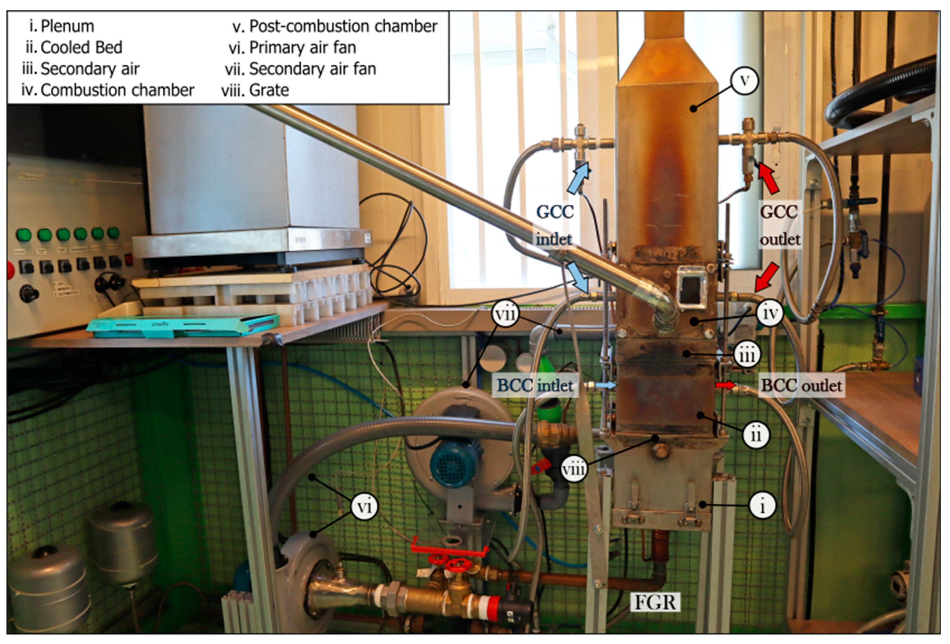
To implement the abovementioned techniques for combustion process improvement, a custom experimental small-scale biomass boiler was designed. It was made of AISI 316L stainless steel with total dimensions of 200 × 200 × 1500 mm (length × width × height). The grate has an effective internal cross-section of 150 × 150 mm. The combustion unit was designed to produce between 11 and 18 kW, providing a specific thermal power of 500–800 kW/m². The unit was designed for working mainly with pelletized biomass, although other forms such as chips would be allowed. Figure 1 includes a scheme of the complete combustion facility, including auxiliary circuits and the combustion unit modules.
The modular configuration of the plant allows for interchanging the position of each part according to the different experimental requirements. This, together with the large number of variables that are able to be measured, provides high versatility in the amount of information that can be extracted from the experimental plant.
As depicted in Figure 1, the designed experimental plant is formed by the:
- (i)
- Plenum, which is where the primary air flows upwards in the facility. It is used for initiating the combustion reaction. Before the air reaches the fuel bed, the air passes through the grate, which consists of 625 holes with 3 mm diameter, which equates to a 20% open area.
- (ii)
- Cooled bed, which is formed by three rows of heat exchanger tubes and cooling jackets on the four walls. In addition, it also has an array of nine K-type thermocouples, which allow for monitoring temperature profiles inside the pellet bed during the whole burning test.
- (iii)
- Secondary air module, whose purpose is to provide the airflow used to complete the combustion of the unburned species formed during the first stages of the combustion. It has a single row of 45° oriented holes. This configuration enables the airflow to enter the combustion chamber with a swirl effect, which promotes turbulence; thus, a proper mixing of the oxidizing agent and fuel occur.
- (iv)
- Combustion chamber, which also has cooled walls. Its removable frontal face has the fuel inlet and a small visor for performing visual inspection of the flame during the combustion experiment. It has two temperature probes where a B-type thermocouple is inserted for flame temperature measurements.
- (v)
- Post-combustion chamber, where the secondary oxidation takes place. It is a refrigerated module that, as well as the bed, has three rows of tubes acting as heat exchangers in its upper zone. It allows for the possibility of inserting a block of a ceramic porous material in cases when flame confining is required.
2.2. Strategies for Combustion Improvement. Implemented Systems
2.2.1. Air Stratification
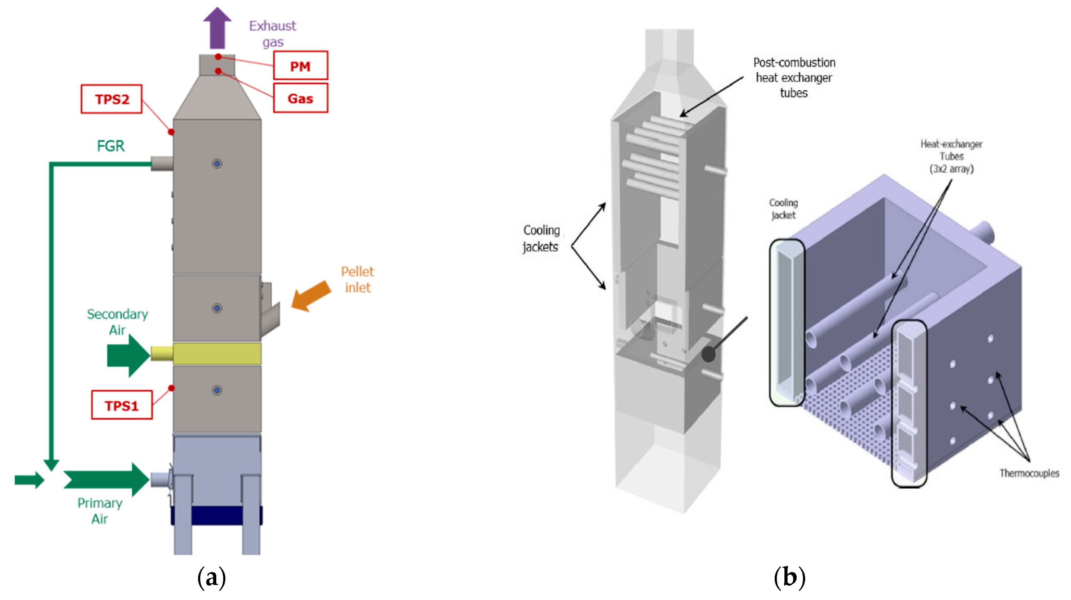
As depicted in Figure 2a, the combustion unit has separate inlets: on the one hand, the air that is needed for starting the combustion reaction and that primarily reacts with the potentially combustible species (basically C, H, S, N) named “primary air”. On the other hand, the air used in a later combustion phase is used for complete oxidation of the unburned species (named “secondary air”). Proper control of the air entering each combustion phase improves the process efficiency, reduces undesired emissions and deposition problems, and lengthens the lifespan of the combustion installation [10].
Air is supplied by two centrifugal single inlet fans (Soler & Palau CBB 60 N). In this case, the regulation of the airflow is performed through throttle valves as the initial method. The air mass flow is measured through two hot-film air-mass sensors (HFM) located at the primary and secondary inlets. The measurement principle is based on the heat that is dissipated when a determined airflow passes through the warmed sensor. The selected meter was a Bosch HFM 5, version 1.
2.2.2. FGR
The combustion unit incorporates the “Internal Flue Gas Recirculation” technique (IFGR). A portion of the hot exhaust gases are suctioned by the primary air fan, bypassed through a cooled conduct and mixed with the fresh primary air before entering the plenum.
The recirculating air flow is defined according to a lambda probe-based regulation. The system has two wideband lambda sensors (Bosch LSU 4.9D) located in both the FGR line, λFGR, and plenum inlet, λpl. The system is able to establish a fixed O2% in the exhaust gas, continuously applying a mass balance to the FGR bypass, according to Expression (1):
where refers to the oxygen content in the fresh air supplied by the primary fan (typically, ambient air); refers to the recirculated gas; and refers to the air entering through the plenum module.
The difficulty of this control process relies on the fact that the operator and control system should be able to simultaneously regulate the FGR needle valve and the feeding rate to provide stable combustion (a fixed O2% within the exhaust gas). Furthermore, the recirculated gas flow passes through a refrigerated pipe that enables a temperature reduction from 400 to 50 °C, avoiding the introduction of an excessively hot mixture for the primary oxidation.
2.2.3. Refrigeration System
The experimental plant was designed as a refrigerated unit, having two separated cooling circuits to remove the produced heat (Figure 2b). The first circuit is used for cooling the bed named bed cooling circuit (BCC), and the other cooling circuit provides the refrigeration of the combustion and post-combustion chambers plus the FGR line named general cooling circuit (GCC). As previously mentioned, the main characteristic of the present plant is the refrigeration of the fuel bed. The planned experiments will focus on the study of its influence in the combustion reaction and emissions, aiming to establish the implications of introducing cold walls in that zone.
Circulating water was selected as the coolant responsible for receiving the energy produced during combustion. Each circuit has a pumping unit (DAB, Evotron 80), a flowmeter (pulsed output single jet water meter DALC/25) and a dissipation fan (Ferroli, AE-F series) of 5 kW and 20 kW for the BCC and GCC, respectively.
The system also has the capability of water temperature control by the use or lack of the different dissipation mechanisms: (1) internal recirculation-short circuit; (2) external recirculation-long circuit, with dissipation fan off; (3) external recirculation, with dissipation fan on.
2.2.4. Temperature Monitoring
The water temperature in the cooling circuits is measured with PT100 thermometers. They are located at six strategic points along the experimental boiler: inlets and outlets of the BCC and GCC.
In addition, 6-mm diameter K-type thermocouples were selected for measuring temperatures along the post-combustion chamber and in the chimney, as well as in the FGR line. Nevertheless, the extremely high values expected to in the flame zone, surpassing 1400 °C, have induced the use of a B-type thermocouple. Since these high-temperature applications are not common and the working atmosphere is expected to be aggressive, a custom-made coated thermocouple was used. The final diameter of the B-type thermocouple was 6 mm, and the selected material for the external protection was sintered Al2O3. This ceramic covering provides sensor resistance against slag and fouling deposition, chemical attack from its environment (condensation of corrosive alkali salts), thermal shocks and hermitic sealing to environmental conditions [21].
Specifically, the bed module presents a temperature mapping system consisting of an array of nine K-type thermocouples. Its configuration allows continuous monitoring of the temperatures of the different bed zones in 3D at different heights and distances from the ignition zone (see Figure 2b). The location of each thermocouple can be changed in the XY axis, allowing for different 3D map configurations according to the selected disposition patterns (aligned or staggered). The K-type thermocouples were covered by stainless steel beans that protected the sensing device from the high temperatures of the flame zone and the aggressive ambient of the combustion chamber.
The main application of the presented system lies in obtaining information about how the combustion is performing inside the bed. Bed temperatures provide feedback about the propagation of the flame and reaction along the fuel or disturbances in the reaction originating from the presence of the cold walls (refrigeration), primary and secondary air entrances, etc., which would be translated into adjustments in the associated sub-systems.
2.2.5. Auxiliary Systems
The fuel feeding circuit is composed of a hopper from which the pellets are transported to the combustion unit through an ascending endless screw (Ferroli 0U2000X0). The hopper is situated on a scale (Radwag WLC C2/K), which continuously records the mass, and it is located so that the fuel enters the combustion chamber by gravity drop and passes through a stainless steel tube. The feeding rate is controlled by means of the feeding cycles: the system has a timer that allows for the regulation of the on-off periods of the screw motor.
Regarding the determination of the main substances present within the exhaust gas flow, the facility has a sampling probe connected to a SERVOMEX 4900 gas analyser after passing through a conditioning unit to remove remains of moisture and condensed species. The analyser uses electrochemical cell sensors that allow for the continuous measurement of the concentrations of O2, CO2, CO and NO.
The total suspended PM concentration is determined by gravimetric methods. A vacuum pump isokinetically pulls the exhaust through the sampling line, which uses a critical orifice that ensures a gas flow of 12 lpm. Quartz fibre filters of 47 mm diameter are used for PM collection. In addition, a thirteen-stage low-pressure impactor, DEKATI DLPI, is used to measure the mass-size distribution. Each impactor stage has a 25 mm aluminium filter, which receive a thermal treatment before and after each test applying the standard norm UNE-303-5:2012. The sampling line and both the filter holder and the DLPI are heated at 120 °C to avoid water condensation. Furthermore, thermophoretic sampling (TPS) can be performed to study the morphology of the emitted particles. The TPS system and transmission electron microscope (TEM) methodology have already been described in a previous study [22]. Figure 2a includes the location of the different sampling points used in the facility.
2.3. Design of Experiments
Initially, a series of 10 preliminary tests were carried out to establish the transient period duration and the stability of the facility. The control parameters that define the test set are displayed in Table 1. As stated by Regueiro et al. [23], the quality of the fuel plays a relevant role in plant stability. According to this, woody pellets were used due to their low ash content (<1% weight, dry basis). A detailed fuel analysis can be found in previous works [22].
Then, different experiments were carried out varying the operating configuration, in order to study the limiting operating conditions for both implemented systems. Tests were named “raw” when both BCC or FGR systems were turned off, and “cooled bed (CB)” or “FGR” depending on the tested configurations. Table 2 includes the defining control variables for each type of experiments.
3. Preliminary Results
3.1. Plant Stability and Repeatability
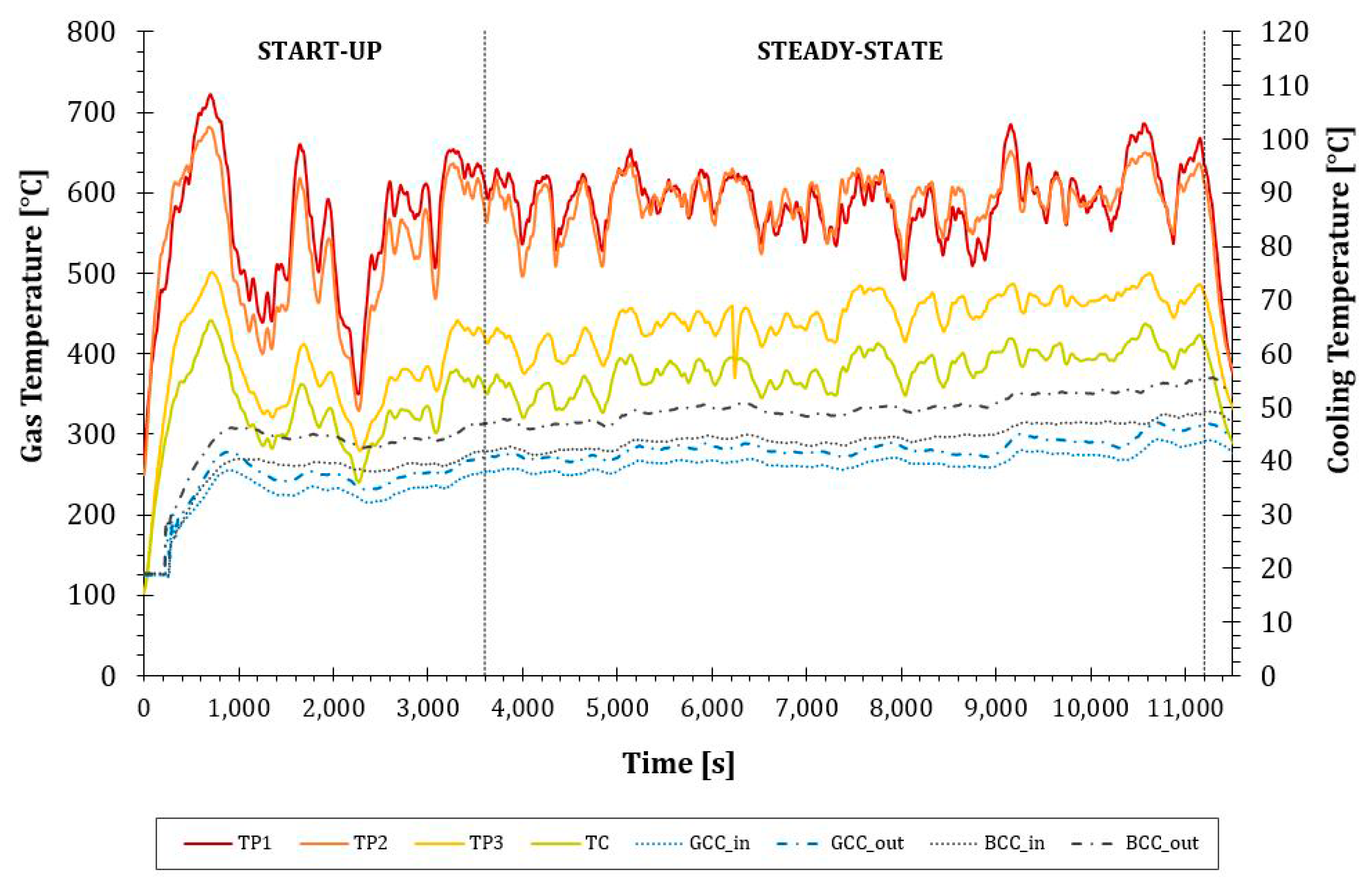
As abovementioned, the transient period duration and the stability of the facility were stablished according to the plant response to preliminary tests. The main operating parameters (burning rate, gas and cooling water temperatures) were analysed. The initial transient period was characterized by intense signal oscillations, which were stabilized within a ±10% deviation band. This stabilization period was shorter than 50 min in every case. The total duration of the experiments was established by a 60 min start-up (transient), followed by a stable period of 125 min (steady state) and then a 10 min switch-off (transient). Figure 3 illustrates the post-combustion and cooling temperatures during a complete experiment, specifying the abovementioned phases. The oscillating pattern in stable time evolution curves is assumed to be inherent to the discontinuous feeding system, as mentioned in a previous work [24].
Once the steady period was established, the repeatability of the plant was studied in terms of the relative deviation of exhaust gas and burning rates within the preliminary test set. The results show relative deviations up to 7.28% for the exhaust gas temperature and 5.21% in the burning rate, which confirm an adequate behaviour of the experimental device.
3.2. Operation of the Implemented Systems: Cooled Bed
Regarding the cooling system analysis, a series of tests at different configurations were performed, named “raw” and “cooled bed”, when the BCC system was turned on or off. The GCC system was turned on in every experiment.
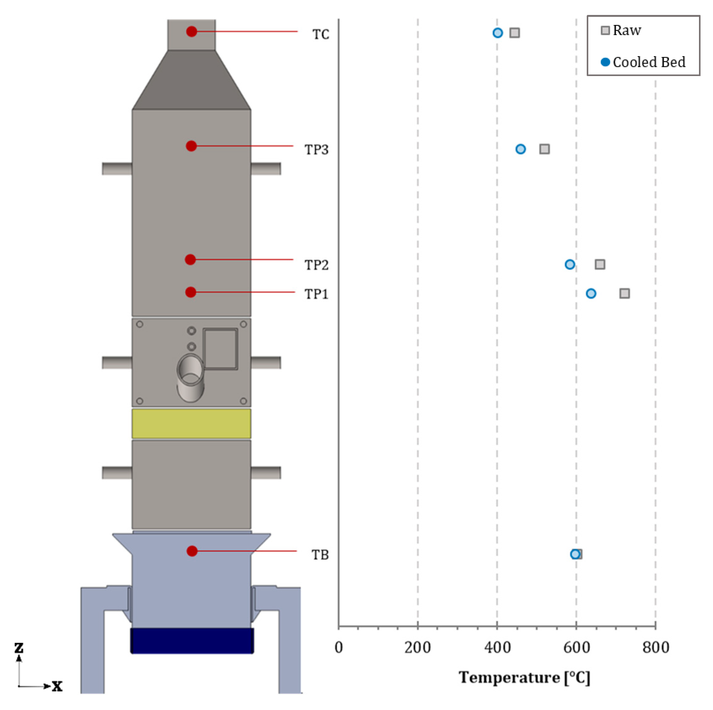
The cooling effect is reflected in the exhaust gas temperature profiles along the whole plant, as depicted in Figure 4, where the temperature reduction is clear, being stronger when closer to the flame-front zone. The dissipation ability of the cooling system was determined by studying each water circuit separately. The regular operation of the GCC in the highest dissipation level is characterized by water temperatures in the range of 45–50 °C, obtaining an average increase of 5–7 °C. The BCC system was able to obtain a maximum temperature increase of 9 °C and was stabilized at temperatures between 50–60 °C (Figure 3). With this configuration, the cooling system was allowed to extract between 5–7 kW, which is approximately half of the thermal power generated in the combustion process. The study also revealed that the cooling capacity of the BCC was 3 kW, which remained constant for every experiment. This value is considerably higher than other plants working with cooled beds, such as the facility proposed by Gerigh et al. [3] with 0.5 kW. Nevertheless, it was evidenced that the initial BCC configuration limited the refrigerating system performance. Therefore, after the preliminary experiments, the 5-kW heater was substituted with an 8-kW unit. The new BCC configuration has a higher temperature increase range (from 8 to 20 °C), which increases the portion of the evacuated heat in the bed from one third to a half of the total dissipated by the whole system.
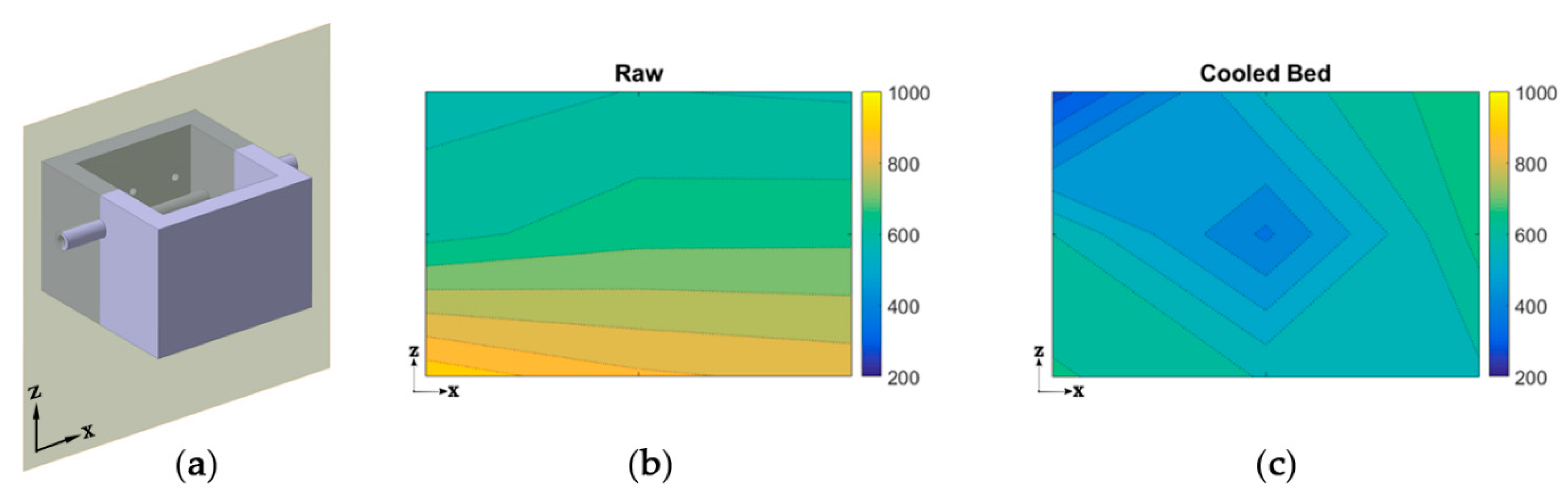
Figure 5 depicts the temperature maps obtained in the central transversal section of the bed module for a raw and a cooled-bed experiment with the 8-kW configuration. Results are displayed for a transversal section of the module, along plane ZX. The difference in temperature distribution profiles and the influence of the BCC circuit in the flame temperature can be observed, with decreasing values especially in the core of the module (from 680 °C to 390 °C).
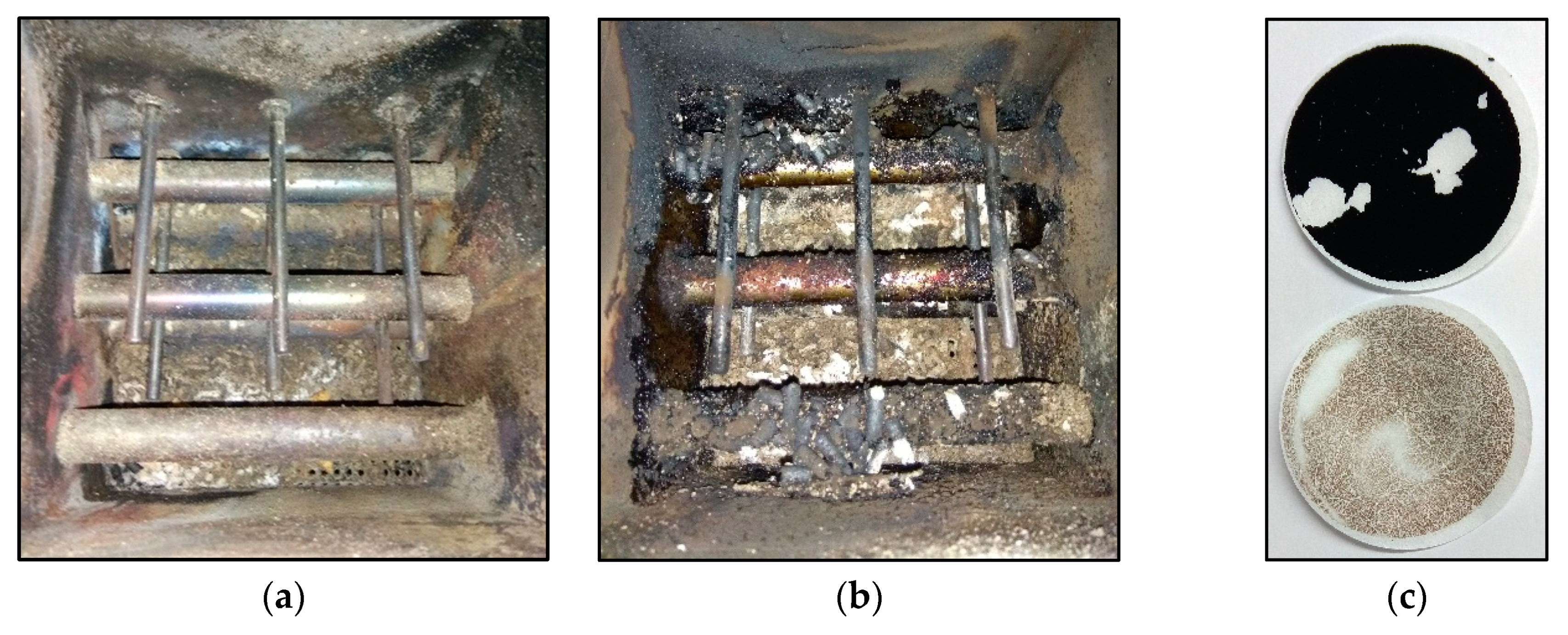
In addition, these changes in bed temperature resulted in strong differences in deposit formation and PM emissions. As shown in Figure 6a,b, when the BCC is activated, the reduction in bed temperatures enhances the condensation of certain compounds in its exchanger tubes. The sticky nature of these substances leads to the retention of more residual matter in the cold walls of the bed, resulting in the decrease in the released PM. In addition, according to the appearance of the sampled matter, the released PM is mainly inorganic for cooled bed experiments (Figure 6c). The preliminary results show a considerable decrease in PM released due to the effect of bed refrigeration, obtaining values up to 70%. This trend was also found by Petterson et al. [25], Jones et al. [26] and Alonso [27]. Therefore, it is expected that the fouling deposition tendencies in the heat exchangers are strongly affected by the presence of a cooled bed. This effect will be further investigated in future work as it is beyond the goals of the current paper.
3.3. Operation of the Implemented Systems: FGR
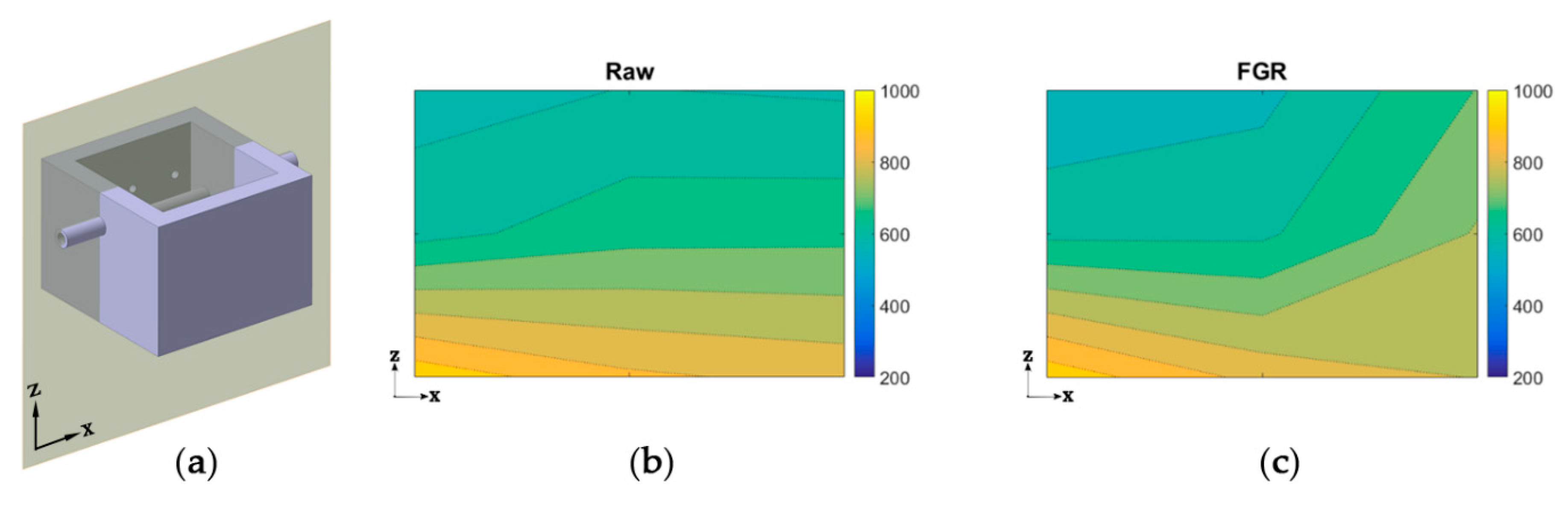
Regarding the flow gas recirculation system (FGR), a series of tests at different configurations were performed, named “raw” and “FGR”. Temperature maps obtained in the central transversal section of the bed module for a raw and FGR experiment are depicted in Figure 7. The influence in the temperature profile can be perceived. As expected, the recirculation of a portion of primary air through the plenum helps to decrease the bed temperature. This effect becomes more evident in the horizontal profile, where the well-stratified profile is changed by a central temperature reduction. It is notable that for preliminary tests, the bed height rises to one third of the total module; thus, the abovementioned phenomenon indicates that the recirculation would have implications as a bed-temperature controller.
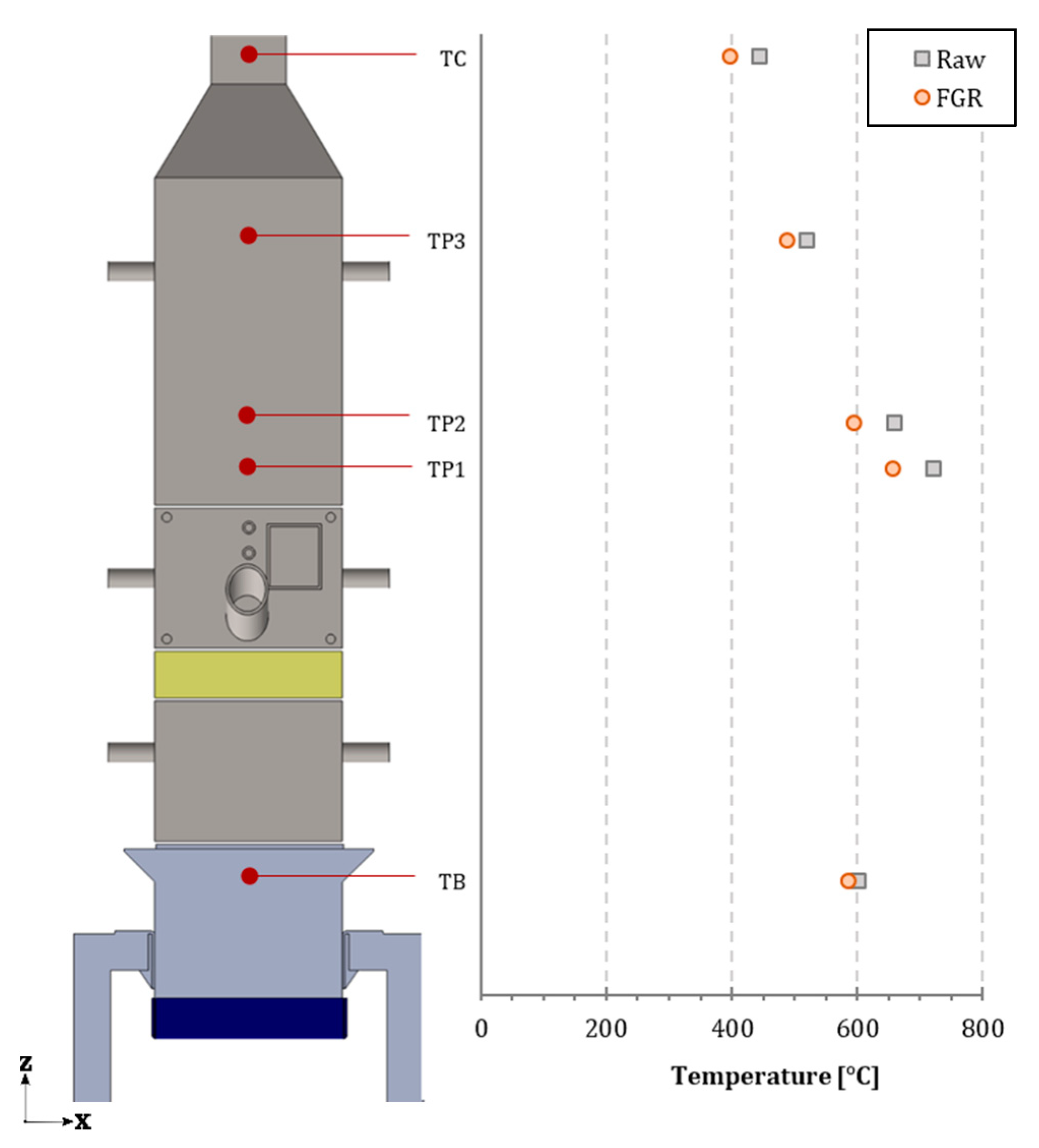
Regarding the effect in the exhaust gas temperature profile, the preliminary tests show slightly lower values in the case of FGR. According to the literature [5], this can be attributed to the reduction of the oxidizing-fuel ratio due to the recirculation of a less O2 rich gas. This implies diminished reactivity potential and, therefore, lower reaction temperatures in both zones, bed and exhaust gas, as depicted in Figure 8. The PM emissions were reduced up to 65% when the recirculation was activated, with apparently low or null fouling formation in the bed heat exchangers. As previously mentioned, the implications of the FGR on PM emissions, composition and fouling phenomena need to be further investigated in future works.
Comparing the FGR and the cooling bed effects, the results show similar temperature variations along the exhaust gas flows. Interestingly, from the operating point of view, this study supports the possibility of controlling the bed and exhaust temperature through two different methods: direct bed cooling in regular air inlets, and decreasing the O2 presence through FGR. In addition, this work allows for the possibility of studying a hybrid solution that combines both methods and its commercial viability.
4. Conclusions
The experimental plant was effectively set up and it was able to work under stable and repeatable conditions. The numerous variables that are measured allow to characterize the combustion processes in a very complete way.
The preliminary results show the effective role of the refrigerated bed, which is responsible for a considerable temperature reduction in the fuel bed as well as in the exhaust gas. This cooling effect is also suspected of decreasing the released particulate matter (PM), which is detrimental to deposit formation in the internal facility surfaces. Moreover, similar trends were found using the flue gas recirculation (FGR) technique in both exhaust temperatures and particle emissions. In addition, the recirculation apparently did not contribute to enhance the fouling formation.
According to the presented results, the possibility of using these two methods for temperature control in combustion units is demonstrated. Therefore, further studies are needed to clarify the implications of cooled bed and FGR in biomass systems. In this sense, future research will be aimed at analysing their influence on gaseous and PM emissions in detail by focusing on the effects in terms of particle morphology and composition. Furthermore, these preliminary results open the door for the study of the combination of bed cooling and recirculation techniques as an interesting hybrid solution.
Author Contributions
Conceptualization, J.P. and D.P.; Methodology, R.P.-O.; Data curation, R.P.-O.; Investigation, R.P.-O. and D.P., Writing—original draft preparation, R.P.-O.; Writing—review and editing, D.P. and J.P.; Project supervision, J.L.M. All authors have read and agreed to the published version of the manuscript.
Funding
This research was financially supported by the project RTI-2018-100765-B100 of the Ministry of Science, Innovation and Universities (Spain). The work of Raquel Pérez-Orozco has been supported by the grant FPU-15/02430 of the Ministry of Education, Culture and Sports (Spain).
Conflicts of Interest
The authors declare no conflict of interest.
Abbreviations
The following abbreviations are used in this article
| BCC | Bed cooling circuit |
| FGR | Flue gas recirculation |
| GCC | General cooling circuit |
| HFM | Hot-film air-mass sensor |
| IFGR | Internal flue gas recirculation |
| O2,FGR | Oxygen content in the recirculated gas [%] |
| O2,pf | Oxygen content supplied by the primary fan [%] |
| O2,pl | Oxygen content entering through the plenum [%] |
| PM | Particulate matter |
| TB | Bed temperature [°C] |
| TC | Chimney temperature [°C] |
| TEM | Transmission electron microscope |
| TP | Post-combustion temperature [°C] |
| TPS | Termophoretic sampling |
| λFGR | Air excess in FGR line (-) |
| λpl | Air excess in plenum (-) |
References
- Vicente, E.D.; Alves, C.A. An overview of particulate emissions from residential biomass combustion. Atmos. Res. 2018, 199, 159–185. [Google Scholar] [CrossRef]
- Nussbaumer, T. Combustion and Co-combustion of Biomass: Fundamentals, Technologies, and Primary Measures for Emission Reduction. Energy Fuels 2003, 17, 1510–1521. [Google Scholar] [CrossRef]
- Gehrig, M.; Pelz, S.; Jaeger, D.; Hofmeister, G.; Groll, A.; Thorwarth, H.; Haslinger, W. Implementation of a firebed cooling device and its influence on emissions and combustion parameters at a residential wood pellet boiler. Appl. Energy 2015, 159, 310–316. [Google Scholar] [CrossRef]
- Díaz-Ramírez, M.; Sebastián, F.; Royo, J.; Rezeau, A. Influencing factors on NOX emission level during grate conversion of three pelletized energy crops. Appl. Energy 2014, 115, 360–373. [Google Scholar] [CrossRef]
- Houshfar, E.; Khalil, R.A.; Løvås, T.; Skreiberg, Ø. Enhanced NOx reduction by combined staged air and flue gas recirculation in biomass grate combustion. Energy Fuels 2012, 26, 3003–3011. [Google Scholar] [CrossRef]
- Nussbaumer, T. Aerosols from biomass combustion. In Technical Report on Behalf of the IEA Bioenergy Task 32; Verenum Research, Zurich, and Lucerne University of Applied Sciences and Arts: Horw, Switzerland, 2017; p. 32. [Google Scholar]
- Nuutinen, K.; Jokiniemi, J.; Sippula, O.; Lamberg, H.; Sutinen, J.; Horttanainen, P.; Tissari, J. Effect of air staging on fine particle, dust and gaseous emissions from masonry heaters. Biomass Bioenergy 2014, 67, 167–178. [Google Scholar] [CrossRef]
- Khodaei, H.; Guzzomi, F.; Patiño, D.; Rashidian, B.; Yeoh, G.H. Air staging strategies in biomass combustion-gaseous and particulate emission reduction potentials. Fuel Process. Technol. 2017, 157, 29–41. [Google Scholar] [CrossRef]
- Khodaei, H.; Guzzomi, F.; Yeoh, G.H.; Regueiro, A.; Patiño, D. An experimental study into the effect of air staging distribution and position on emissions in a laboratory scale biomass combustor. Energy 2017, 118, 1243–1255. [Google Scholar] [CrossRef]
- Regueiro, A.; Jezerská, L.; Patiño, D.; Pérez-Orozco, R.; Nečas, J.; Žídek, M. Experimental study of the viability of low-grade biofuels in small-scale appliances. Sustainability 2017, 9, 1823. [Google Scholar] [CrossRef] [Green Version]
- Wiinikka, H.; Gebart, R. The influence of air distribution rate on particle emissions in fixed bed combustion of biomass. Combust. Sci. Technol. 2005, 177, 1747–1766. [Google Scholar] [CrossRef]
- Tsiliyannis, C.A. Emissions and Power Losses due to Biofuel or Biomass Nitrogen: Assessment and Prevention Mechanisms. Energy Fuels 2016, 30, 9396–9408. [Google Scholar] [CrossRef]
- Hu, Y.; Yan, J. Characterization of flue gas in oxy-coal combustion processes for CO2 capture. Appl. Energy 2012, 90, 113–121. [Google Scholar] [CrossRef]
- Granados, D.A.; Chejne, F.; Mejía, J.M.; Gómez, C.A.; Berrío, A.; Jurado, W.J. Effect of flue gas recirculation during oxy-fuel combustion in a rotary cement kiln. Energy 2014, 64, 615–625. [Google Scholar] [CrossRef]
- Duan, F.; Chyang, C.-S.; Lin, C.-W.; Tso, J. Experimental study on rice husk combustion in a vortexing fluidized-bed with flue gas recirculation (FGR). Bioresource Technology 2013, 134, 204–211. [Google Scholar] [CrossRef]
- Li, P.-W.; Chyang, C.-S. A comprehensive study on NOx emission and fuel nitrogen conversion of solid biomass in bubbling fluidized beds under staged combustion. J. Energy Inst. 2019, 93, 324–334. [Google Scholar] [CrossRef]
- Tu, Y.; Zhou, A.; Xu, M.; Yang, W.; Siah, K.B.; Subbaiah, P. NOX reduction in a 40 t/h biomass fired grate boiler using internal flue gas recirculation technology. Appl. Energy 2018, 220, 962–973. [Google Scholar] [CrossRef]
- Chen, Q.; Zhang, X.; Zhou, J.; Sharifi, V.N.; Swithenbank, J. In Effects of Flue Gas Recirculation on Emissions from a Small Scale Wood Chip Fired Boiler. Phys. Procedia 2015, 66, 65–68. [Google Scholar] [CrossRef] [Green Version]
- Zhang, L.-H.; Chyang, C.-S.; Duan, F.; Li, P.-W.; Chen, S.-Y. Comparison of the thermal behaviors and pollutant emissions of pelletized bamboo combustion in a fluidized bed combustor at different secondary gas injection modes. Energy 2016, 116, 306–316. [Google Scholar] [CrossRef]
- Gehrig, M.; Jaeger, D.; Pelz, S.K.; Kirchhof, R.; Thorwarth, H.; Haslinger, W. Influence of a Direct Firebed Cooling in a Residential Wood Pellet Boiler with an Ash-Rich Fuel on the Combustion Process and Emissions. Energy Fuels 2016, 30, 9900–9907. [Google Scholar] [CrossRef]
- Pyszko, R.; Brestovič, T.; Jasminská, N.; Lázár, M.; Machů, M.; Puškár, M.; Turisová, R. Measuring temperature of the atmosphere in the steelmaking furnace. Measurement 2015, 75, 92–103. [Google Scholar] [CrossRef]
- Patiño, D.; Pérez-Orozco, R.; Porteiro, J.; Lapuerta, M. Characterization of biomass PM emissions using thermophoretic sampling: Composition and morphological description of the carbonaceous residues. J. Aerosol Sci. 2019, 127, 49–62. [Google Scholar] [CrossRef]
- Regueiro, A.; Patiño, D.; Porteiro, J.; Granada, E.; Míguez, J.L. Effect of air staging ratios on the burning rate and emissions in an underfeed fixed-bed biomass combustor. Energies 2016, 9, 940. [Google Scholar] [CrossRef]
- Pérez-Orozco, R.; Patiño, D.; Porteiro, J.; Cid, N.; Regueiro, A. Influence of the Feeding Rate on the Transient Behavior of a Biomass Combustor. Chem. Eng. Technol. 2019, 42, 2520–2529. [Google Scholar] [CrossRef]
- Pettersson, A.; Niklasson, F.; Moradian, F. Reduced bed temperature in a commercial waste to energy boiler - Impact on ash and deposit formation. Fuel Process. Technol. 2013, 105, 28–36. [Google Scholar] [CrossRef]
- Jones, F.; Niklasson, F.; Lindberg, D.; Hupa, M. Effects of reduced bed temperature in laboratory-and full-scale fluidized-bed boilers: Particle, deposit, and ash chemistry. Energy Fuels 2013, 27, 4999–5007. [Google Scholar] [CrossRef]
- Alonso, M.; Rodriguez, N.; Gonzalez, B.; Arias, B.; Abanades, J.C. Capture of CO2 during low temperature biomass combustion in a fluidized bed using CaO. Process description, experimental results and economics. Energy Procedia 2011, 4, 795–802. [Google Scholar] [CrossRef] [Green Version]
Figure 1.
Scheme of the internally cooled bed facility, including plant modules and water circuits: general cooling circuit and bed cooling circuit (GCC and BCC, respectively).
Figure 1.
Scheme of the internally cooled bed facility, including plant modules and water circuits: general cooling circuit and bed cooling circuit (GCC and BCC, respectively).

Figure 2.
(a) Air-gas circuits and sampling points, including thermophoretic (TPS1 and TPS2), particulate matter (PM) and gas. (b) Configuration of the cooling system and detail of the cooled bed module.
Figure 2.
(a) Air-gas circuits and sampling points, including thermophoretic (TPS1 and TPS2), particulate matter (PM) and gas. (b) Configuration of the cooling system and detail of the cooled bed module.

Figure 3.
Time evolution of temperature signals for a complete experiment. The left axis represents the gas temperatures along the plant from the post-combustion module (TP1, TP2, and TP3) to the chimney (TC). The right axis represents the cooling temperatures before and after the combustion for both water circuits: general (GCC in and out) and bed (BCC in and out).

Figure 4.
Gas temperature profile along the combustion unit for experiments with and without bed refrigeration (Cooled Bed and Raw, respectively). Temperatures were measured in the pellets (TB), in the post-combustion chamber (TP1, TP2, TP3) and in the chimney (TC).
Figure 4.
Gas temperature profile along the combustion unit for experiments with and without bed refrigeration (Cooled Bed and Raw, respectively). Temperatures were measured in the pellets (TB), in the post-combustion chamber (TP1, TP2, TP3) and in the chimney (TC).

Figure 5.
Temperature map of the central bed module section, plane ZX (a) for an experiment performed under raw (b) and cooled bed (c) conditions. Total airflow: 9 kg/h; air stratification: 50% primary-50% secondary; feeding cycle: 1 [s] ON–8 [s] OFF; temperatures are in °C.
Figure 5.
Temperature map of the central bed module section, plane ZX (a) for an experiment performed under raw (b) and cooled bed (c) conditions. Total airflow: 9 kg/h; air stratification: 50% primary-50% secondary; feeding cycle: 1 [s] ON–8 [s] OFF; temperatures are in °C.

Figure 6.
View of the residues retained in the bed module and the grate after a test (a) without bed refrigeration and (b) with cooled bed. (c) PM filters sampled during a raw (upper) and a cooled bed (bottom) experiment.
Figure 6.
View of the residues retained in the bed module and the grate after a test (a) without bed refrigeration and (b) with cooled bed. (c) PM filters sampled during a raw (upper) and a cooled bed (bottom) experiment.

Figure 7.
Temperature map of the central bed module section, plane ZX (a) for an experiment performed under raw (b) and flue gas recirculation-FGR (c) conditions. Total airflow: 9 kg/h; air stratification: 35% primary-15% FGR-50% secondary; feeding cycle: 1 [s] ON–7 [s] OFF; temperatures are in °C.
Figure 7.
Temperature map of the central bed module section, plane ZX (a) for an experiment performed under raw (b) and flue gas recirculation-FGR (c) conditions. Total airflow: 9 kg/h; air stratification: 35% primary-15% FGR-50% secondary; feeding cycle: 1 [s] ON–7 [s] OFF; temperatures are in °C.

Figure 8.
Gas temperature profile along the combustion unit for experiments with and without flue gas recirculation (FGR and Raw, respectively). Temperatures were measured in the pellets (TB), in the post-combustion chamber (TP1, TP2, TP3) and in the chimney (TC).
Figure 8.
Gas temperature profile along the combustion unit for experiments with and without flue gas recirculation (FGR and Raw, respectively). Temperatures were measured in the pellets (TB), in the post-combustion chamber (TP1, TP2, TP3) and in the chimney (TC).


Table 1.
Control variables defining the preliminary test set.
| Constant Parameter | Value |
|---|---|
| Total airflow | 6 [kg/h] |
| Air staging (%primary/%secondary) | 30%/70% |
| Feeding cycle (time ON/time OFF) | 1/9 [s] |
| Cooling bed system | ON |
| Flue gas recirculation (FGR) system | OFF |
Table 2.
Control variables defining raw, cooled bed (CB), and flue gas recirculation (FGR) experiments.
Table 2.
Control variables defining raw, cooled bed (CB), and flue gas recirculation (FGR) experiments.
| Constant Parameter | Value | ||
|---|---|---|---|
| Experiment set name | Raw | Cooled Bed (CB) | Flue gas recirculation (FGR) |
| Total airflow [kg/h] | 6; 9 | 6; 9 | 6; 9 |
| Air staging (%primary/% secondary) | 30%/70% | 30%/70% | 30%/70% |
| 50%/50% | 50%/50% | 50%/50% | |
| Cooling bed system | OFF | ON | OFF |
| General cooling system | ON | ON | ON |
| Flue gas recirculation (FGR) system | OFF | OFF | ON |
© 2020 by the authors. Licensee MDPI, Basel, Switzerland. This article is an open access article distributed under the terms and conditions of the Creative Commons Attribution (CC BY) license (http://creativecommons.org/licenses/by/4.0/).
Share and Cite
MDPI and ACS Style
Pérez-Orozco, R.; Patiño, D.; Porteiro, J.; Míguez, J.L. Novel Test Bench for the Active Reduction of Biomass Particulate Matter Emissions. Sustainability 2020, 12, 422. https://0-doi-org.brum.beds.ac.uk/10.3390/su12010422
AMA Style
Pérez-Orozco R, Patiño D, Porteiro J, Míguez JL. Novel Test Bench for the Active Reduction of Biomass Particulate Matter Emissions. Sustainability. 2020; 12(1):422. https://0-doi-org.brum.beds.ac.uk/10.3390/su12010422
Chicago/Turabian StylePérez-Orozco, Raquel, David Patiño, Jacobo Porteiro, and José Luís Míguez. 2020. "Novel Test Bench for the Active Reduction of Biomass Particulate Matter Emissions" Sustainability 12, no. 1: 422. https://0-doi-org.brum.beds.ac.uk/10.3390/su12010422
Note that from the first issue of 2016, this journal uses article numbers instead of page numbers. See further details here.