ABGS: A System for the Automatic Generation of Building Information Models from Two-Dimensional CAD Drawings

Department of Computer Engineering, Chung-Ang University, 84 Heukseok-Ro, Seoul 06974, Korea
*
Author to whom correspondence should be addressed.
Sustainability 2020, 12(17), 6713; https://0-doi-org.brum.beds.ac.uk/10.3390/su12176713
Submission received: 16 June 2020
/
Revised: 10 August 2020
/
Accepted: 12 August 2020
/
Published: 19 August 2020
(This article belongs to the Special Issue Human-Centric Urban Services)
Abstract
:Building Information Modeling (BIM) refers to 3D-based digital modeling of buildings and infrastructure for efficient design, construction, and management. Governments have recognized and encouraged BIM as a primary method for enabling advanced construction technologies. However, BIM is not universally employed in industries, and most designers still use Computer-Aided Design (CAD) drawings, which have been used for several decades. This is because the initial costs for setting up a BIM work environment and the maintenance costs involved in using BIM software are substantially high. With this motivation, we propose a novel software system that automatically generates BIM models from two-dimensional (2D) CAD drawings. This is highly significant because only 2D CAD drawings are available for most of the existing buildings. Notably, such buildings can benefit from the BIM technology using our low-cost conversion system. One of the common problems in existing methods is possible loss of information that may occur during the process of conversion from CAD to BIM because they mainly focus on creating 3D geometric models for BIM by using only floor plans. The proposed method has an advantage of generating BIM that contains property information in addition to the 3D models by analyzing floor plans and other member lists in the input design drawings together. Experimental results show that our method can quickly and accurately generate BIM models from 2D CAD drawings.
1. Introduction
In the field of architecture, design drawings provide important information on all the design-related aspects of buildings to be constructed. After the era of making designs using paper, pens and various manual tools, that is, since the 1970s, drawings have been prepared using Computer-Aided Design (CAD). In the early 2000s, Building Information Modeling (BIM) emerged as a widely accepted concept. BIM refers to the modeling (i.e., planning, design, structure/equipment/electricity engineering, construction, maintenance, and even disposal) of facilities in multi-dimensional virtual spaces. In addition, BIM includes information on all activities related to the modeling as well as the model itself. BIM encompasses the related technologies, software, and processes, and concepts [1,2].
Governments consider BIM as a major means of advancing architectural technology and have conducted substantial research in collaboration with academia to establish BIM in the market. For example, the Public Procurement Service of the Korean government required the application of BIM in the initial public offering stage for projects costing of 50 billion KRW or greater; this requirement applied to all public construction bids from 2011. Since then, this requirement has been gradually expanded to apply to all projects subject to customized services for procurement service construction orders starting in 2018.
The active efforts of governments to promote the use of BIM are favorable conditions for establishing it. However, the development of national standards, clarification of the roles between companies, and settlement of systems for public orders are still insufficient. This can result in additional expenses such as research and development costs and initial facility investment costs, making it difficult for private enterprises to actively utilize BIM, because it is not easy to achieve profits by adopting it [3]. There have also been major problems associated with using BIM in design offices since its introduction. These problems include the lack of skilled BIM users and software compatibility issues. In addition, the building permission system and design environment remain in their existing two-dimensional (2D) form, and it is difficult to improve productivity due to the mix of BIM and CAD. Consequently, 2D drawings are still required for collaboration among different business entities [4]. Therefore, it is necessary to recreate 2D drawings using BIM design files, and research has also been conducted to automatically generate 2D drawings using BIM [5]. In addition, small and medium-sized architectural firms, which represent the majority, often employ existing 2D-based designs while BIM partners transform 2D drawings into three-dimensional (3D) models to produce 3D, 4D, and 5D BIM results. Hence, it is unreasonable to rapidly introduce BIM manufacturing tools to field workers who are only proficient in CAD.
Scan-to-BIM [6] is one of the widely known methods for conveniently generating BIM. This is a method to construct a BIM using data generated by scanning a target building with a laser scanner, or photo data taken using a drone or a camera. This is a work that can be done on a building that has already been built, so that this alone has no way of knowing whether the building was built as intended by the designer, agreed by the owner, approved by the relevant public agency before the actual work has started. Therefore, in order to verify whether the completed construction was performed according to the original CAD design, the BIM for the design and the BIM for the actual building must be created and compared, respectively. For this purpose, a 2D-to-BIM, or CAD-to-BIM, method is often required.
With this motivation, we propose the development of a system that automatically generates BIM models from 2D drawings prepared using CAD and outputs the results as an Industry Foundation Classes (IFC) file, where IFC is an international standard format. The overall idea of this method is depicted in Figure 1. Unlike most traditional methods analyzing only floor plans to detect structural components through pattern analysis of symbols and lines, our method can be more accurate for detecting structural components because it analyzes the floor plans after limiting the type and characteristics of structural components to be shown in the floor plan through the analysis of member lists as well as floor plans. Furthermore, the proposed system has an advantage of creating data properties in addition to geometric information (i.e., 3D models) by analyzing floor plans and member lists (i.e., column list, beam list, slab list, wall list, etc.) together. This can reduce the risk of information loss that may occur during the process of conversion from CAD to BIM. Another important advantage is that our method is able to process CAD drawings without using layer information while keeping reasonable processing speed. The layer provided by CAD is a convenient function and CAD workers create layers for each member such as column layer and beam layer in many cases. As a result, there are attempts to separate the members denoted on a floor plan using the layers in most of existing methods. However, since drawings of a single member can be divided into multiple layers in reality, the existing methods may fail to function correctly in such case. Therefore, it is often advantageous to be able to process CAD input independent of layers with reasonable speed.
A building is designed to form a structure that can resist all forces acting on it, enabling it to maintain its shape and position. The structure is also called a framework because it forms the skeleton of a building. Building structures can be classified according to various criteria. Based on the materials that make up the structures, building structures can be classified as wood structures, brick structures, cement block structures, reinforced concrete structures, steel frame structures, steel-reinforced concrete structures, etc. Based on the type of structure, they can be classified into Rahmen structure, wall structure, truss structure, arch structure, and many others. Most modern residential and commercial facilities are built with Rahmen or wall-type structures using reinforced concrete. The elements that constitute this structure are called members, which include foundations, columns, beams, walls, and slabs. Detailed information on the material composition and the location of these members in a building is provided in the design drawings. Our work mainly focuses on the creation of a software system (SW) that performs BIM for the four main members of the frame (i.e., column, beam, wall, and slab) and the floor plan in the structure of a building that employs reinforced concrete. Urban services in smart cities often require digital modeling of urban infrastructures. The proposed system also facilitates the digital modeling and smart management of urban infrastructures, especially buildings, with low cost.
The remainder of this paper is organized as follows. Section 2 presents previous studies related to CAD drawings and BIM generation. With regard to establishing a system that automatically generates BIM models using CAD-prepared 2D drawings, Section 3 discusses the basics of the input design drawings and output IFC file formats that will be used for the proposed system. Section 4 describes the details of the proposed system, and Section 5 provides the analysis results of the implemented system. Finally, we present our conclusion in Section 6.
2. Related Work
CAD has been used to prepare design drawings for several decades. Research on analyzing CAD drawings and automatically producing relevant results has a long history. CAD can be utilized to develop a consistent system for structural analysis, section calculation, and frame evaluation [7]. Architectural drawing recognition technology has been studied to effectively handle large amounts of CAD drawings in digital form [8]. Hsu et al., demonstrated a technique for extracting and automatically classifying text information from 2D drawings drawn using CAD to effectively manage numerous design drawings [9]. Systems can extract information from CAD drawings and calculate the volume based on the extracted information. These studies focused on printing CAD-prepared design drawings for image analysis, directly analyzing the state of the file to extract the desired information, and automating the task of classifying or objectifying this information. Although the aforementioned previous attempts may differ from our method in terms of actual implementation, the basic concept of extracting and objectifying appropriate information from design drawings is an underlying commonality.
Several related studies, such as those on converting IFC files into other formats, modifying the contents of the file itself, or analyzing the contents to extract and process building-related information have been conducted. Zhu et al., proposed an open-source approach that converts IFC file data to a shape file in order to utilize the BIM information in a geographic information system (GIS) [10]; this approach included an enhanced automatic multipatch generation algorithm to achieve this transformation effectively [11]. In a study by Ying et al., the IFC model expresses a curved surface as a polyhedron shape. An algorithm for creating a new IFC BIM model was developed to ensure that the polyhedron shape has the correct geometric relationship [12]. A framework to determine whether model elements are correctly mapped to the IFC class by searching for IFC BIM components was developed [13]. Lin et al., proposed i-GIT, which uses geometrical information from IFC models to create an indoor route [14]. Zhang et al., developed an algorithm that automatically analyzes BIM models in IFC files and suggested preventive measures for various cases that are related to falls [15]. Rio et al., conducted a study to further define and enter the attribute information contained in IFC files to examine whether the building violated the prescribed law [16]. With regard to the issues of eco-friendliness and energy conservation, Andriamamonjy et al., proposed a method of analyzing IFC files to automatically enter the information required for an eco-friendly housing performance assessment program [17]. Chen et al., developed an algorithm to extract IFC-based cladding requirements for building energy performance assessment [18].
In the field of computer science and engineering, the technology for automatically creating BIM models based on 2D horizontal and vertical drawings can be considered as already mature [19]. A comprehensive survey of this technology was described in Yin et al. [20]. Such technologies are also already available in the field of architectural design. In fact, there have been many attempts to create 3D design information from various underlying data. Such attempts can be divided into two main types: (i) constructing BIM models by scanning, photographing, and analyzing a building using devices such as lasers or cameras for its operation and maintenance [21], (ii)preparing a 3D design directly from drawings or related information.
Regarding the first type, the construction of 3D indoor information through ground laser scanning was performed [22,23]; furthermore, Li et al. [24] compared the 2D vector data extracted using a ground radar (LiDAR) with architectural design drawing data to analyze the usability of 3D indoor information. Lu et al., created a system that automatically analyzes images of buildings taken using digital cameras to recognize building surface materials and store them in the IFC format [25,26,27]. A low-cost RGB-D cameras can be used for automatic generation of indoor as-built BIM models [28]. Regarding the second type, most approaches are based on automatic or semiautomatic analysis of architectural floor plans [29] including topological information [30,31]. The input can be scanned plans [32,33,34] as well as mechanical drawings [35,36]. The conversion from 2D information to BIM models often requires recognition of 2D data and 3D model reconstruction processes [37,38]. Lee et al., analyzed 2D design data to automatically generate terrain information in three dimensions, particularly after the completion of civil engineering works [39]. Zlatanova et al., conducted a study regarding the creation of 3D spatial information using a 2D fire target drawing [40]. Semantic ambiguities may occur during the conversion process from 2D CAD data to 3D BIM models. Zhang et al. [41] addressed this problem by eliminating the ambiguities and improving information integrity. Similar algorithms for the reconstruction of 3D models from floor plans can be also used for immersive virtual reality applications [42]. In a recent work, Beacons coupled with BIM models were used to provide location and guidance inside a building in real time [43].
Most existing studies of the second type are characterized by analyzing only the floor plan, regardless of whether using scanned 2D floor plans or CAD files. If all we want is just a simple 3D model, not BIM, this can be enough. However, what we want is often a BIM that contains property information in addition to 3D models. Given that all the information required for the construction is included in the drawings and specifications, more drawings in addition to the floor plan can be analyzed to obtain valuable results, and thus a method to do so like ours is desirable.
The term automation means that a software handles a majority of the work that is supposed to be done manually. It is necessary to further clarify the meaning of “automation”, which can be considered with regard to two aspects: (i) the number of stages of a manual process that are being executed by the software and (ii) the proportion of the total manually written or entered information that is handled by the software. The former is referred to as process automation, whereas the latter as information input automation. It is very important that these two are satisfied simultaneously, including the required extent of satisfaction.
In terms of process automation, CAD generally supports layer functionality, and it is common for CAD users to use it for creating design drawings. For example, a user creates a column layer to draw a column, and a beam layer to draw a beam. Then, when developing an analysis algorithm, one may want to use the patterns drawn by the user such that the function works by inferring the characteristics of the layer; however, one cannot ensure that only the members that correspond to that layer are included. If the design drawings are directly modified, beams may inadvertently be drawn on column layers. In this case, drawing beams on an inappropriate layer is only an internal problem with regard to CAD, and a combined drawing will be seen from the perspective of those who see the printed designs on any layer. However, a software that analyzes drawings on a layer-by-layer basis will face difficulties in this regard. Accordingly, several CAD analysis softwares require users to assign layers before starting the analysis. The meaning of each layer should be designated by the user. Similarly, when processing the entire file is difficult, users can drag each area using a mouse to specify that area. These methods significantly reduce the degree of automation of the process.
There are open source BIM projects and related softwares that can be freely used for BIM modeling and visualization [44]. Table 1 summarizes a list of such projects. On the other hand, there are commercial BIM platforms that can be used for BIM modeling as well as analysis and visualization. Revit by AutoDESK and ArchiCAD by Graphisoft, which are considered leaders in introducing BIM design software to design offices, support outputting files in the IFC format in addition to their own output file formats.
3. Input and Output Information
We divide the architectural design process into the (i) planning, (ii) intermediate, and (iii) implementation steps. In the planning step, architects set design goals for a building and present a potential plan based on the data provided by the owner. Architects also propose a plan for establishing the design concept and the basic system, and obtain approval from the owner. In this step, architects or designers identify basic information for the design based on the overall data of the building as well as the related facilities and sites. Generally, cadastral maps, urban planning charts, and survey charts are used; however, as the aforementioned maps and charts often differ from the ground truth, the conditions of the surroundings should be checked through onsite surveys. Through these planning steps, the outlines of the building size, composition, flow plan, layout plan, etc. are devised. An overall policy on the structure, materials, and facilities is discussed with the building owner to draw conclusions.
In the intermediate step, various reviews are performed to clarify the details of the planned design, minimize the possibility of changes in the implementation step, prepare a design document that elucidates the amount and capacity of materials and equipment required according to the system confirmation, and to obtain approval from the owner. In this step, the judgment of administrative agencies and other groups related to the intended building is obtained. The structural plan and facility plan are developed based on the planned design, and the drawings are prepared by accurately indicating the location and dimensions of the structural members.
The implementation step involves the preparation of architecture design documents necessary for bidding, forming contracts, and constructing the building based on the result of the intermediate step so that the scope, quantity, quality, dimensions, location, material, texture, color, etc. of the construction work can be determined. As the name indicates, this step involves the creation of an implementation design drawing with detailed information that can be used during construction. The architecture design document encompasses the drawings of construction works, structural bill of materials, specifications regarding the construction of a building, etc. In other words, the architecture design document contains all the information necessary to proceed with the construction work, including the design drawings, calculation of the budget for constructing the building, and documents related to the geology of the construction sites. Although laws and regulations define what an architecture design document is, they do not define the format of such a document and the content to be included in it. Different users may have different criteria regarding the information required for design drawings and the manner in which that information should be written. Concerned professionals and organizations have made agreements and set standards on the composition and form of design drawings within the people engaged in fieldwork after a regular process in the field of architectural design. One example of such an agreement is the Korean Architectural Documents and Information Standard [45] written by the Korean Architects Association. Although this standard is not mandatory because it is merely a guideline, it serves as a good reference, as it is believed to contain the consensus on design drawings. This standard provides clarification on the types of drawings that should be included when preparing design drawings. In this report, discussions with regard to design drawings are presented based on this standard. The design drawings to be used in relation to the framework within the scope of this paper are those corresponding to the member list and the structural floor plan; hence, we examine the information contained in them, as follows.
3.1. Member List
The member list is a general list for each member: columns, beams, slabs, and walls. This list contains information on the cross-sectional shape of each member. The materials required for each member should be placed in the list. To construct the frames of reinforced concrete structures, which is the main subject of this research, rebars and concrete are used as raw materials. Consequently, the crucial information includes the manner and shape in which the rebars are arranged. Here, we introduce the details of the column list, beam list, slab list, wall list, and structural floor plan, which comprise the member list.
3.1.1. Column List
In the field of architectural and structural engineering, a column is a structural element that transfers the weight of the upper structural elements to other lower structural elements. Columns are often used to support beams on which the upper portions of walls or ceilings are laid. A column list is a table that contains information regarding the columns, e.g., symbol, form (i.e., shape), size, main bar, sub-bar, and hoop. Figure 2a shows a real example of a column list. This column list contains information on column C3 of the basement. A (floor, symbol) pair identifies the column. Column C3 of this basement floor will have the indicated cross-sectional shape, which is in length. The main-bar will comprise 22 HD25 standard bars, the sub-bar will comprise 6 HD13 standard bars, the hoop-bar will comprise HD10 standard rebars at intervals of 300 mm, and the supplementary bars will comprise HD10 standard rebars at intervals of 200 mm. Some of these data may be omitted depending on whether they are essential or optional.
3.1.2. Beam List
A beam is a member installed horizontally between columns. It is designed to transmit the force to the columns horizontally via the slab. A long horizontal member experiences a downward load in the middle owing to the influence of gravity, and the principle of action-reaction causes both ends to rise upward. Because the forces acting on the center of the beam and on both ends of the beam are different, the arrangement of the rebars should also be different. A beam can be divided into an internal end, a center, and an external end. Similar to the column list, the beam list is a table that contains information regarding the beams, such as the symbol, form (i.e., shape), size, top, bottom, stirrup, and subbar. However, the beam is more distinctive than the column. Each beam property is divided into three types (columns in the table) under one symbol. The three types are internal, center/all, and external. Based on the construction criteria, the property “center/all” is mandatory and the columns “internal” and “external” are optional. Thus, cross-section information and rebar information, which are listed under one symbol, can be presented in one column or be divided into two columns or three columns. Figure 2b shows an actual example of a beam list.
3.1.3. Slab List
A slab refers to a floor plate. Similar to the tables for columns and beams, the slab table contains information, such as the symbol, form, thickness, specification of center and end rebars (e.g., Lx and Ly) regarding the slabs. Figure 2c presents a real example of a slab list; this list is different from those corresponding to columns and beams in that there is no sketch of the cross-sectional shape. The cross-sectional sketch of the floor plate is drawn separately and not included in the list.
3.1.4. Wall List
Columns, beams, and slabs are all members of the structure, whereas walls can be built as members of the structure or for finishing. For example, partition walls or brick walls for interior decoration, which are built to temporarily block large spaces, are not members of the structure and cannot support the weight of buildings. Therefore, the walls used for support are called retaining walls, and the corresponding wall lists are called retaining wall lists. Similar to the slab list, there is no shape label in the wall list. Figure 2d presents a real example of a wall list.
3.1.5. Structural Floor Plan
In architecture, a floor plan is a horizontal projection of each floor of a building. A floor plan is drawn for all floors from the basement to the uppermost floor of the building to be built, and horizontal projections for roofs and rooftop floors are also included in the floor plan. Among these plans, a floor plan prepared for structural construction is called a structural floor plan. It contains information on the manner in which all members, such as columns, beams, slabs, and walls, should be placed.
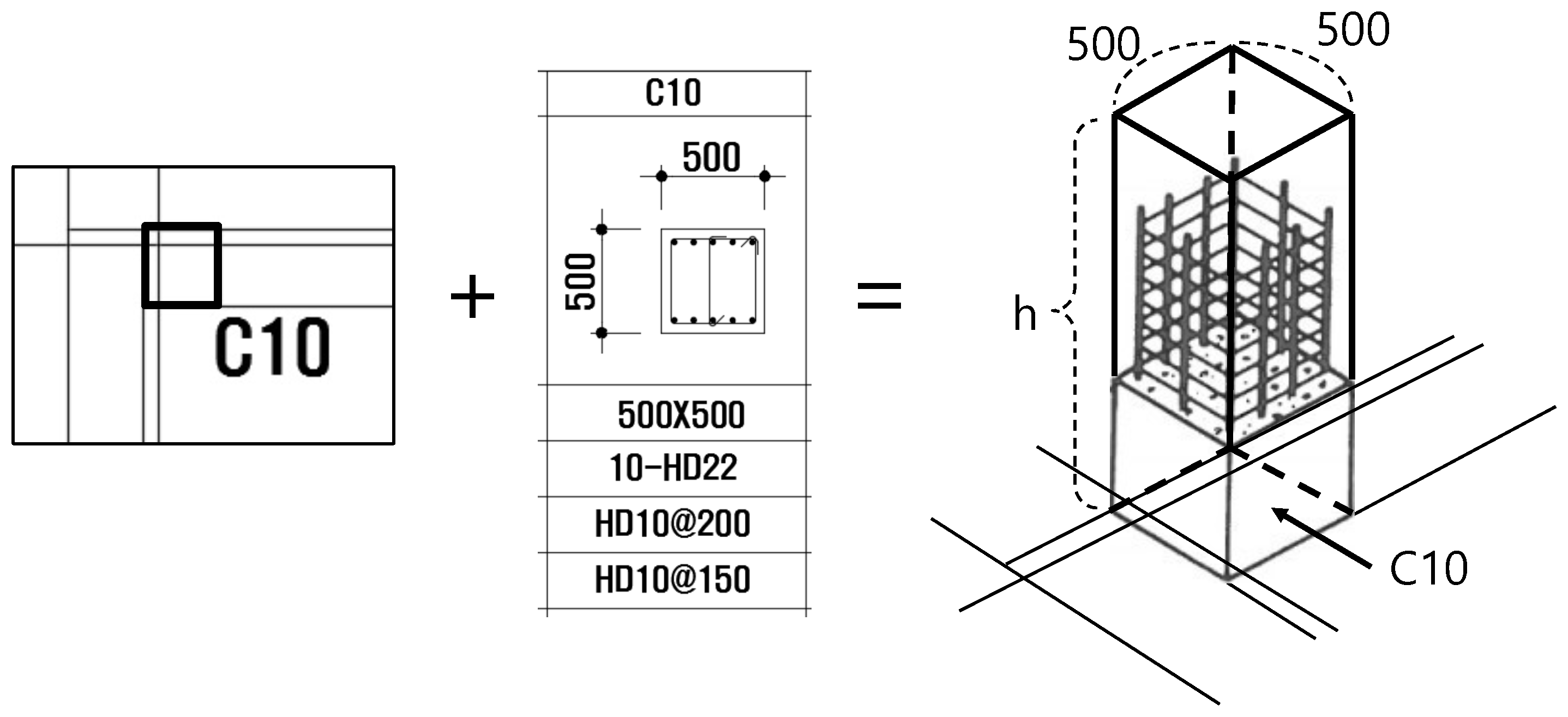
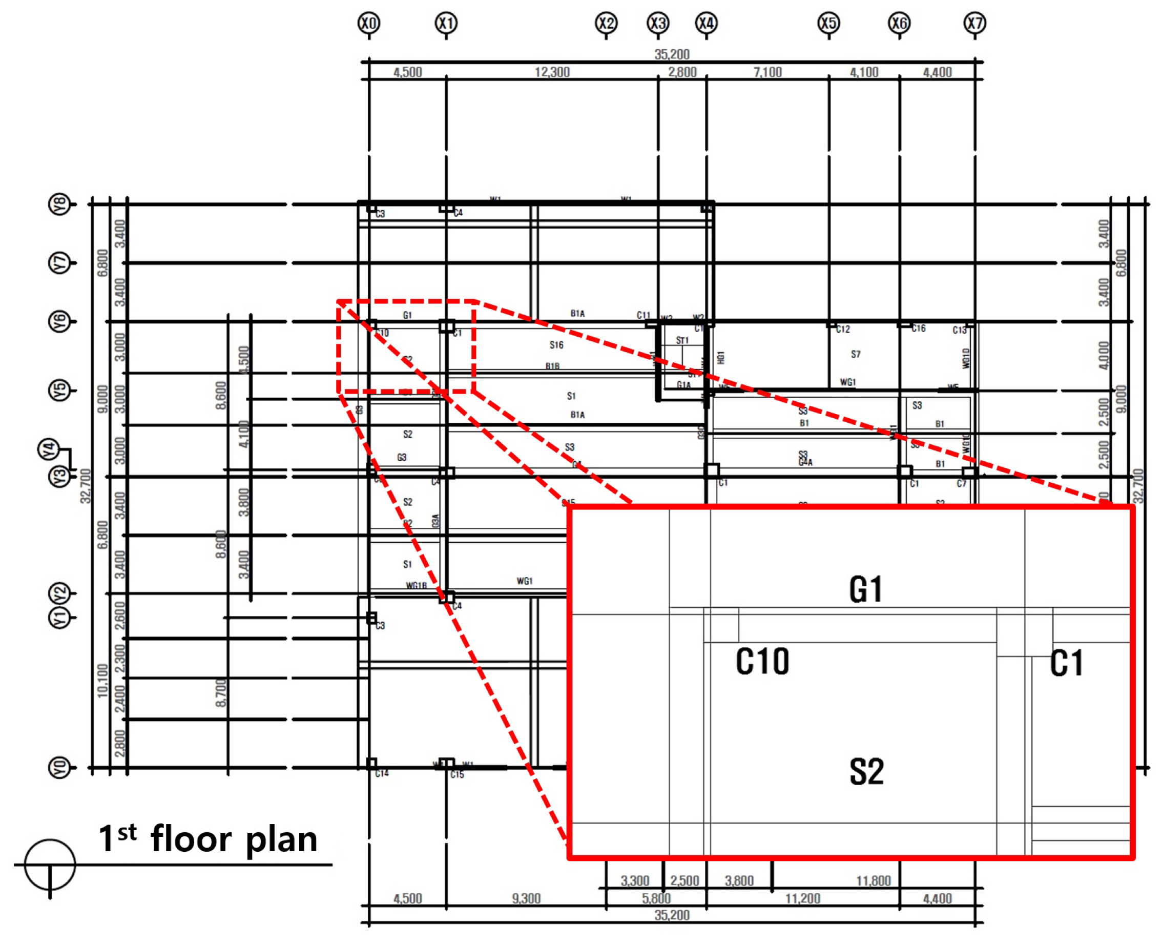
The structural floor plan includes dimension lines consisting of straight lines and numbers. Moreover, members installed on the exterior and interior of the building are also indicated in the plan. Notably, a single member is drawn as a rectangle; however, connected members can be drawn without separation. Next to the rectangle indicating a single member, a symbol, which is the same as that listed in the corresponding member list, is drawn to indicate the member type. For example, in the magnified portion in Figure 3, the symbol C10 is marked and a square is drawn on the upper left. This means that the symbol C10 must exist in the column list; furthermore, columns with rebars and cross-sectional shapes corresponding to the ones listed in (1st floor, C10) in the column list will be placed in the location corresponding to C10 (indicated by a square) in this structural floor plan. If information corresponding to (1st floor, C10) does not exist in the column list, it means that there is an error in the drawing. Thus, in the case of this particular structural floor plan, it is clear that a hexagon (1F, C10) extending vertically as high as 1F will be erected in the position corresponding to C10. Figure 1 shows the example of this construction.
Similarly, the magnified portion in Figure 3 displays a long rectangular shape drawn horizontally between C10 and C1. The cross-sectional shape of a beam (1st floor, G1) in the beam list can be also used to reconstruct a hexagon extending horizontally along the length of the rectangle drawn below G1. Thus, one can reconstruct the entire structure in three dimensions using member lists and structural floor plans.
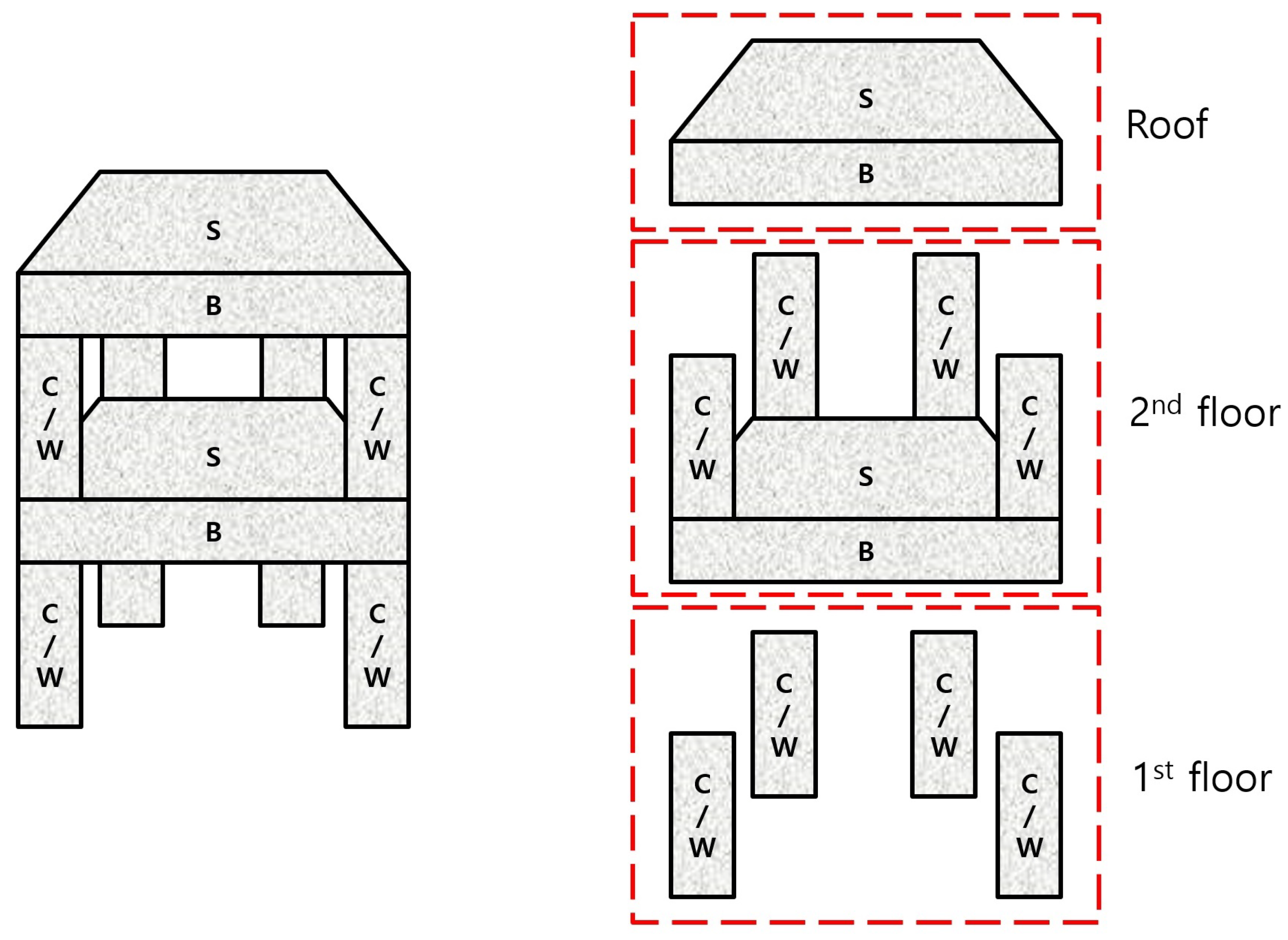
In addition, it is worthwhile to mention that the concept of a floor in a structural floor plan can be slightly different from what general people may perceive as depicted in Figure 4. For example, the structural floor plan of the second floor should contain columns and walls of the second floor and beams and slabs on the first floor. Another characteristic is that columns, beams and walls are rectangular, but the slabs are without rectangles, but only with symbols. The floor plate pointed by this symbol is surrounded by adjacent columns, beams, and walls. In other words, the area of a floor plate is the area drawn inside adjacent columns, beams, and walls.
3.2. IFC File Format
IFC is a standard file format proposed to enable digitized descriptions of facilities, including buildings and civil infrastructure, and their environments. We use IFC as our output format for BIM model generation. The open international standard (ISO 16739) was designed for a variety of hardware devices, software platforms, and interfaces. The related research and promotion are carried out by buildingSMART International (http://www.buildingsmart.org). The IFC file format was published from December 1996 (version 1.0) to April 2019 (version 4.2). Among the various versions, version 2.3.0.1, version 4.0 (ISO 16739:2013), and version 4.0.2.1 (ISO 16719:18) have been used as standards.
It should be noted that buildingSMART International officially recommends the use of the latest version, IFC4.1. Furthermore, buildingSMART International has announced that IFC4.1 is fully compatible with IFC4.0 and with the core definition IFC 2x3 TC1 of 4.1 and 4.0. In spite of this, the list of all software products that support IFC file formats (displayed on the homepage of buildingSMART International) indicates that software support is limited to version 2.3.
4. Automatic BIM Model Generation
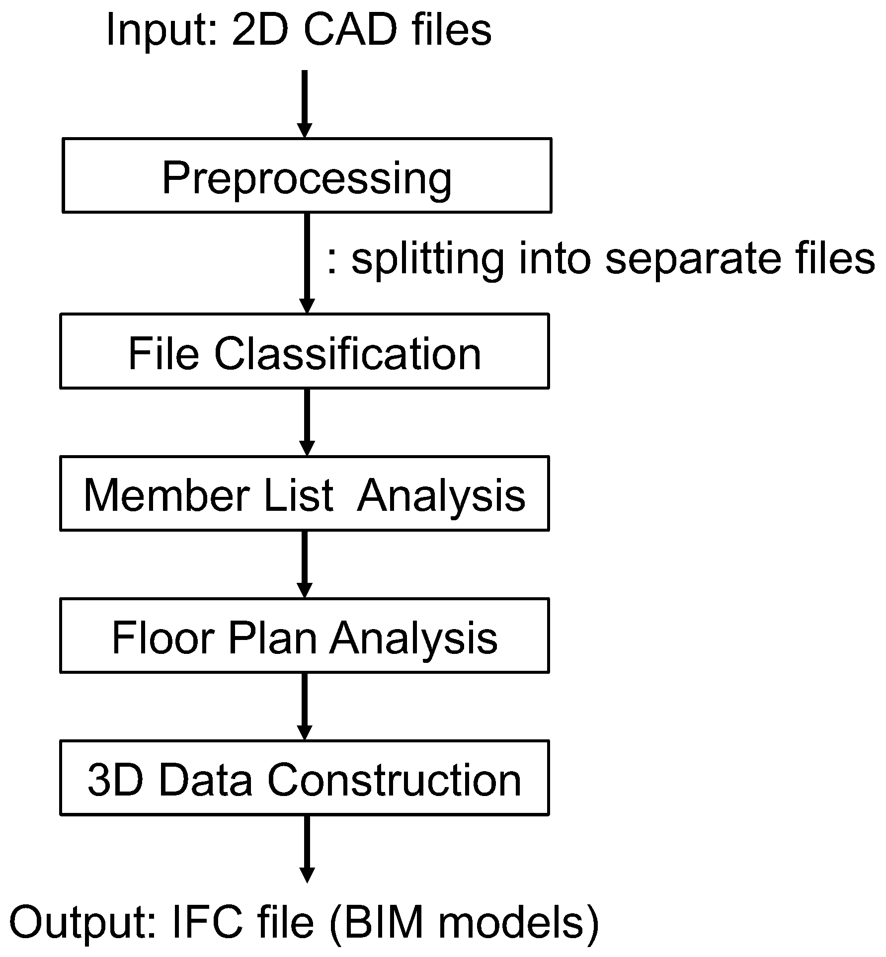
Based on the background knowledge and existing research mentioned previously, we focus on the automatic creation of BIM models from 2D CAD drawings. We also describe the development of the proposed system, termed as the Automatic BIM model Generation System (ABGS), as well as the methods involved. The overall process of the proposed system (i.e., ABGS) is depicted in Figure 5.
4.1. Preprocessing
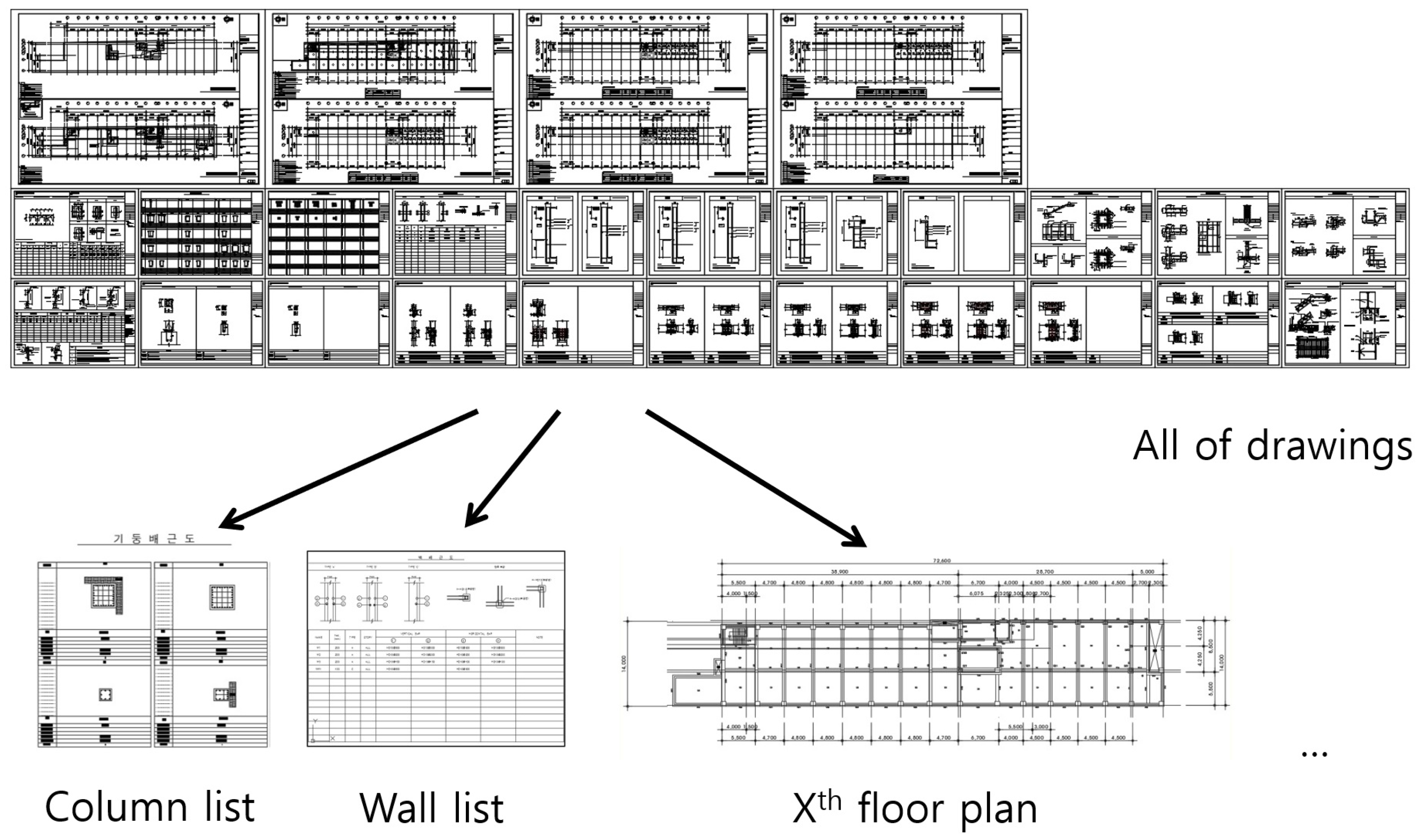
Drawing analysis may be considered the analysis of drawings printed on paper or saved as image files; however, designers typically use CAD to make drawings and then store them in the native format of the CAD software to share them; therefore, a rather unnecessary step is necessitated: outputting the drawing to paper or outputting it as an image. Therefore, this study is based on the direct analysis of CAD files without considering the output phase. In addition, when designers need to infer how to store design drawings in a CAD file, they can collect relevant drawings and store them in one file per group, and in some cases, they can store all drawings in a single file. As the process of analyzing drawings in this study requires analyzing each drawing as a single file, we perform preprocessing to convert the input drawings that are in a combined form into separate drawing files. Figure 6 shows an example of preprocessing.
4.2. Construction of ABGS Process
The ABGS process is divided into the file classification, member list analysis, floor plan analysis, 3D model construction, and output generation steps. In the ABGS, all necessary user inputs are performed at the beginning of the process to eliminate user input during SW execution and ensure automation.
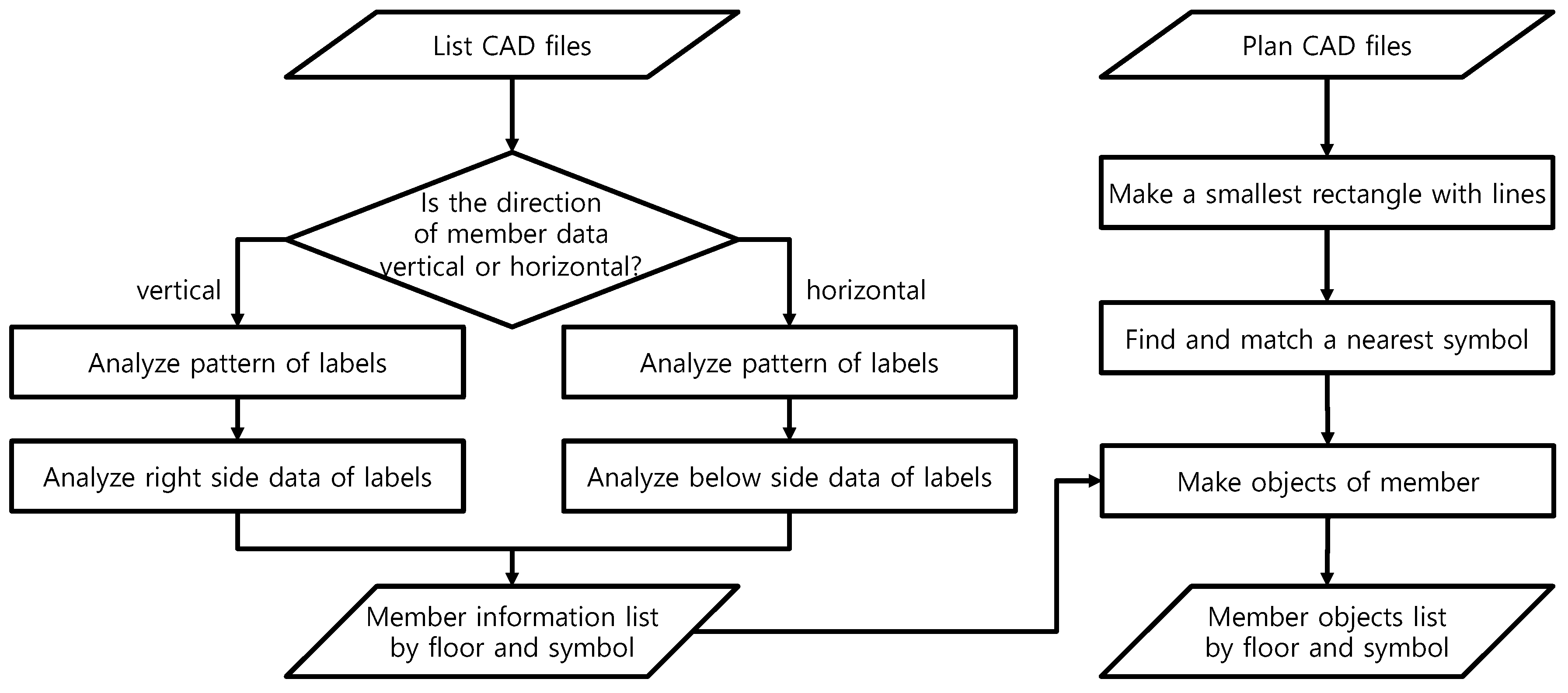
During the initialization of the ABGS, a user creates a project and the necessary buildings. Then, he/she enters the CAD files that he/she wants to convert, including the necessary information, such as the number of floors and floor height. When the user prompts the SW to start the conversion, all processes then proceed internally within the software until the IFC file is output. Figure 5 shows a conceptual flowchart of the entire ABGS process. We describe the working of this process as follows. First, the entered file is classified according to its name, i.e., according to whether it is a floor plan or a list, and the member lists to which it corresponds. The algorithm for extracting information from each member list is not substantially different from the order in which a person reads a drawing. Information is converted, from left to right and from top to bottom, into a list of data structures separated by (floor, sign) pairs. The information that corresponds to the cross-sections of members is extracted from the drawings. The text in the drawings is also extracted to obtain symbols and other member-specific information (i.e., properties). The analysis of list-CAD files is depicted in the left part of Figure 7.
As mentioned in Section 3, the labels in the column list and beam list are displayed in portrait form on the extreme left, and the data corresponding to these labels are written on the right side of the labels. When analyzing the beam list, it is important to note that several cross-sections can possess one symbol. In the slab list, unlike the column list or the beam list, the label is marked horizontally at the top and the corresponding data are displayed at the bottom of the label. If there is more than one type of floor plate, rows will be added at the bottom of the table for each symbol. As the form can be considered as symmetric based on the column list or the beam list, the order in which data are read can be changed from vertical to horizontal. In some cases, different floors may be displayed separately for the same symbol. Because this is also seen as symmetrical based on the origin of the form in which the rebar information is displayed at each end of a single symbol in the view table, the drawing can be analyzed via either vertical reading or horizontal reading. The wall list can be analyzed without difficulty because it possesses the same shape as the slab list; however, it has different labels. After analyzing each list of columns, beams, slabs, and walls, the member information is generated for each (floor, symbol) pair. All floor members have a (floor, symbol) pair as an identifier.
Our method analyzes the member lists and the floor plan of a building in the same way that we can imagine the entire three-dimensional view of the building through the floor plan of each floor. We use the lines drawn on a floor plan to create a rectangle and run an algorithm that creates a pair of the rectangle with its nearest symbol in that floor plan. This method is reasonable because the symbols of the members, which are intended to be perceived by a user, are consistent with the general writing conventions of real people, who tend to draw symbols close to the member to which they correspond. Then, the information extracted from the floor plan and each (shape, symbol) pair are used to perform a search; they are then matched with the information corresponding to each floor symbol. This is a one-to-many match, in which the (floor, symbol) member information resulting from the list analysis is matched to several (shape, symbol) pairs in floor plans. The analysis of floor plan CAD files is illustrated in the right part of Figure 7.
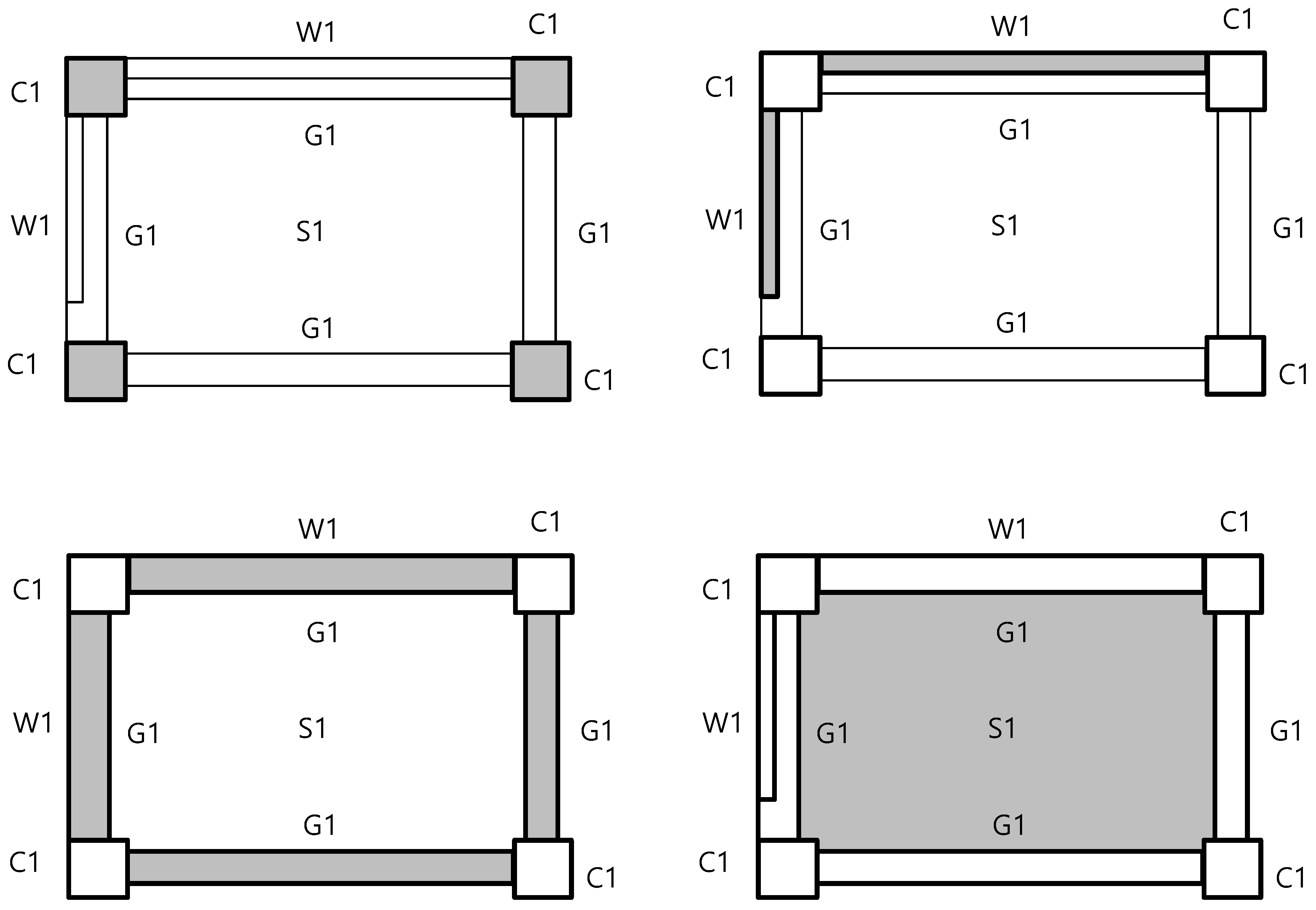
The order of finding each member in the floor plan is as follows. First, find the column in the (shape, symbol) pairs. After the squares of each column are detected, pairs of square and symbol (i.e., shape and symbol) are created by combining the lines existing between the columns. In these pairs of (shape, symbol), we find the walls, followed by the beams. Next, the space surrounded by columns, walls and beams naturally becomes a slab. This is illustrated in Figure 8.
The same symbol may be used several times to represent a member within a floor plan. This does not present any issue and can even be considered natural because this simply means that members with the same attributes will be used in many places. A problem may occur when there is a rectangle in the floor plan and the symbol next to it is not found in any member list. This is because we do not know what this rectangular shape means. Similarly, if there is only a shape but no symbol is given, the meaning of this shape is unknown. Alternatively, if only the symbol is written and no shape is present, the attributes of the member are known, but the location of the member within the plane is unknown, assuming that the information corresponding to the symbol is within the list. In this study, these cases are ignored, and in fact, it would be appropriate to ignore such cases because the design is unclear. However, when considering user convenience, it would be worthwhile to perform a preprocessing analysis and inform the user if there is only a shape or symbol, prior to full-scale operation. It would be also desirable to replace the missing information in the list with the most structurally relevant information and inform the user of this replacement.
Three-dimensional objects are constructed using user-entered height information and inter-planar topology information based on the analysis of member lists and floor plans. The information is saved in a file in accordance with the IFC format. To obtain the output, an open-source project was selected and employed in this study. With regard to the software environment, IFcOpenShell was used; it included developer characteristics, development language support, execution-based OS, and stand-alone application support. The results were saved as IFC2x3 files.
4.3. ABGS Data Structure
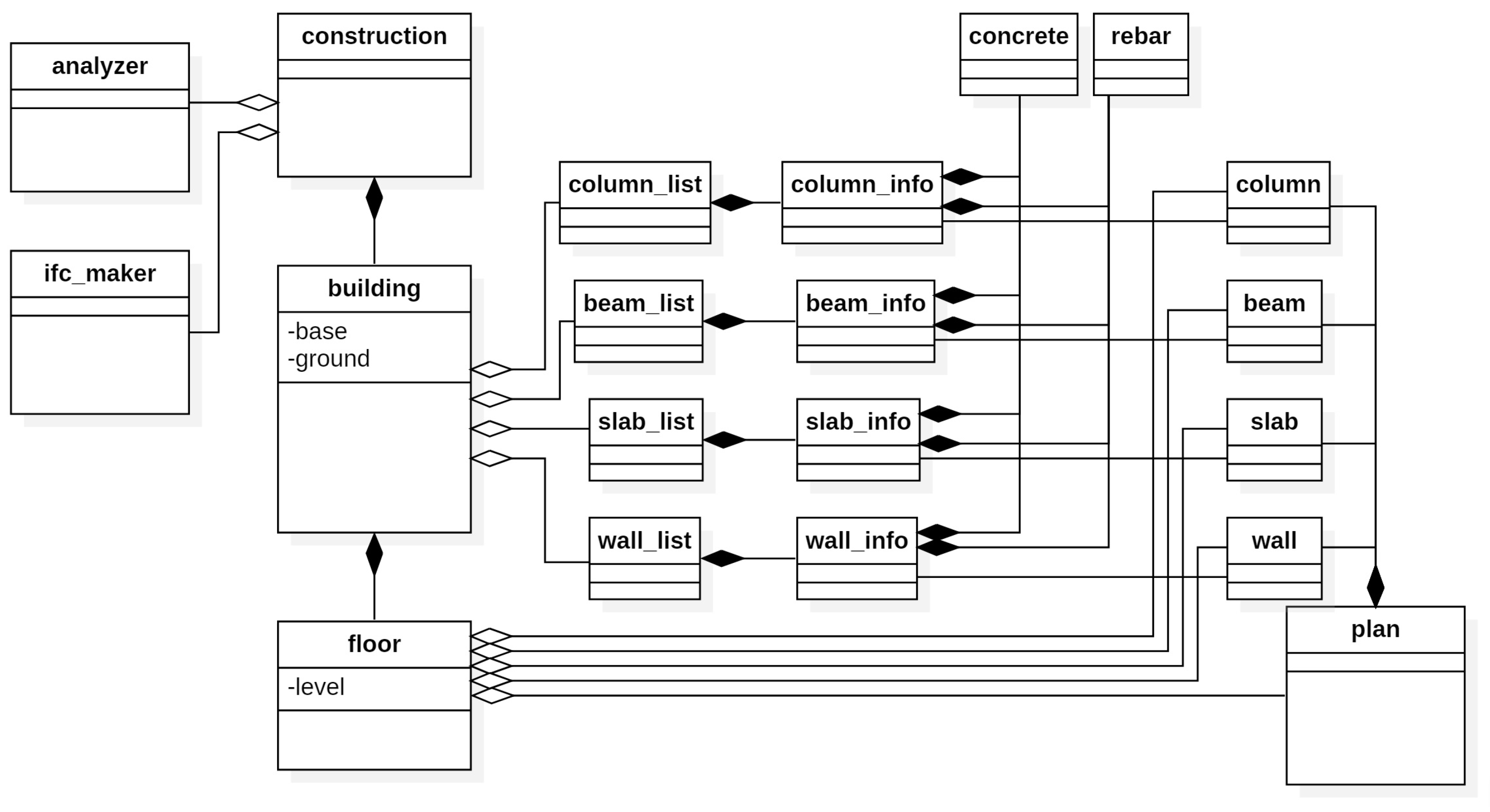
Figure 9 is a class diagram that shows the relationships among data entities in ABGS. In the beginning, one project instance is created for a unit of construction. In one project instance, the user can create and own as many building instances as desired. One building instance contains column_list, beam_list, slab_list and wall_list as raw data and column_info, beam_info, slab_info and wall_info as member information generated from each list drawing. Since our work is based on reinforced concrete structures, the class concrete and the class rebar contain material properties of concrete and rebar, respectively. They also belong to member information. floor instances that belong to the building instance are created as the number of floors entered by the user. Each floor plan instance is matched with a floor instance in a one-to-one manner. A floor object generated via the analysis of the member list based on the floor symbols belongs to a building instance. The floor instance is designed to have drawings for each floor, such as a floor plan, and the information generated from the drawings. Therefore, in the same way that the building instance contains the raw data of each drawing and the information generated from them, the floor instance contains plan instances (i.e., raw data for each floor plan) and column, beam, slab and wall instances that are the generated information. analyzer instance has two roles: (i) generating member information (e.g., column_info, beam_info, slab_info and wall_info) from raw data of each member list and (ii) generating member objects (e.g., columns, beams, slabs and walls) from raw data of each floor plan. ifc_maker instance is responsible for outputting each extracted member object, building information and construction information in the IFC format.
4.4. ABGS User Interface
The ABGS has a menu and a file tree that allows the creation of projects, addition of buildings, and the creation of drawings. The size, height, etc. can also be entered through the property input window corresponding to a building. The desired task can be specified and started through the pop-up menu in the main menu or the file tree, and the output is printed through the output window.
5. Experimental Results
The design drawings represent the shapes of various buildings, and each designer has a unique way of creating design drawings. Therefore, a crucial concern is whether the developed system can account for inter-designer variations among design drawings and produce the desired outcome. Accordingly, we implemented and tested the ABGS system for various architectural datasets. The experiment was conducted on a desktop hardware platform equipped with an Intel Core i5-4570 CPU, 8 GB of main memory, and a Microsoft Windows 7 64-bit operating system.
We selected the following two sets of drawings as experimental data among architectural design drawings with reinforced concrete structures. The selection was performed by considering whether the drawings were representative of the drawing methods employed in various architecture companies and whether they could handle floor settings according to their purpose and various types of floor plans. Table 2 contains the attributes of the selected data.
A project was created to test the ABGS using the experimental data, and a CAD file with floor properties such as size and height was input into the ABGS. After executing the algorithm, the results were saved in the IFC format. The number of each of the four members (i.e., columns, beams, slabs, and walls) in the input CAD file was compared with those in the output IFC file to measure the accuracy of our system and ensure that the form of the BIM model contained in the output was the same as the original building shape intended by the designer. The execution time was also measured.
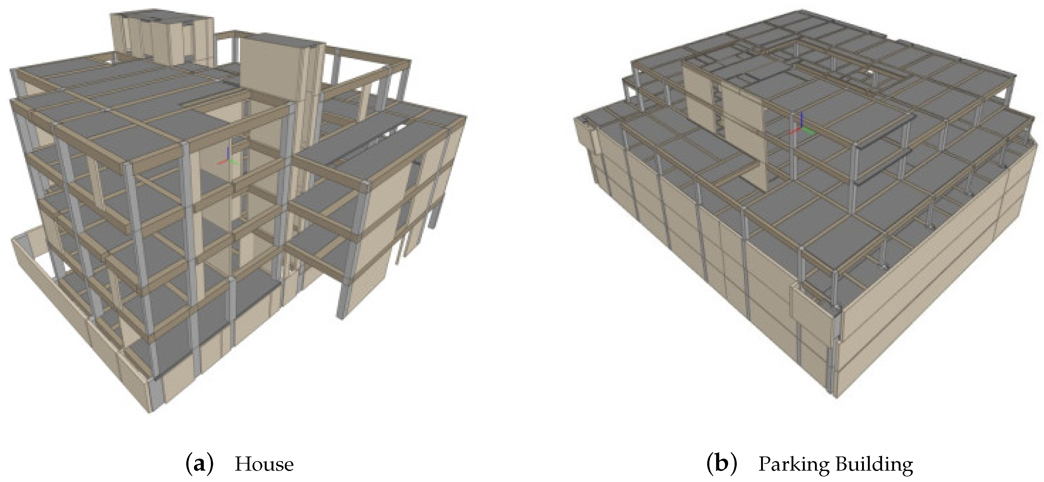
An IFC file was obtained by processing a design drawing for a house with one basement level and four floors above the ground level using our method, as illustrated in Figure 10a. The execution time was 27 seconds, and the results obtained for each of the four members are presented in Table 3. In addition, Table 3 compares the number of symbols in the input CAD drawings and the number of components generated in the output BIM models for each member. The number of columns differs by one in the second, third, and fourth floors above the ground. This was caused by a mismatch between the dimensions indicated on the column list and the dimensions drawn on the floor plan. The column with the symbol C12 occurred once in the second, third, and fourth floors, and the size of the column was in the column list; however, the size of this column was in the floor plan, causing a mismatch. With regard to the beams, there is a difference of two in the third floor above the ground. This was caused by a mismatch between the list and the floor plan, and the symbol on the floor plan of the third floor above the ground was not processed because the symbol was stated as having only one basement floor to two floors above the ground. Regarding the walls, a difference of one was observed for the fourth floor. This is because a symbol was indicated on the floor plan, but there was no corresponding shape; therefore, this instance was not processed because it was unclear whether the designer’s intention was to indicate that the wall existed or whether was the symbol was drawn erroneously.
Similarly, an IFC file was obtained by processing a design drawing for a three-story parking building, as shown in Figure 10b. The execution time was 26 s. The results obtained for each of the four members are summarized in Table 4. Regarding the beams, there is a difference of two for the ground floor and six for the second floor. This difference was caused by the symbol being in the floor plan but not in the beam list.
The processing time increases in proportion to the size of the building; however, there is a significant reduction in the processing time of method compared to that of conventional BIM software. In addition, the number of members before and after each conversion was checked to ensure that the BIM model was created correctly when the information between the member lists and the floor plan was correct, and that basic information for each member object was correctly entered.
6. Conclusions
We proposed a step-by-step process through which BIM models are automatically created from 2D CAD drawings of concrete structures. We also proposed a system (i.e., ABGS) that operates according to the proposed process. We implemented our system and applied it to typical CAD drawings that are actually used in the industry. The proposed ABGS automatically creates a BIM model by directly analyzing CAD file drawings that designers have previously used. The system does not require direct modeling by users unlike conventional BIM softwares, and allows users to easily obtain IFC files representing BIM models from CAD file inputs and a few simple user inputs. It was demonstrated that the ABGS can process a building design with five to six stories within approximately tens of seconds and generate the output. It creates an accurate model, as intended by the designer, as long as the information between the member lists and the floor plan corresponds well. In addition, it has the ability of receiving information that should be provided in a BIM model, such as the attributes of floors and buildings. Using the proposed ABGS, designers who desire to obtain a BIM model but find it difficult to use BIM production tools can obtain an IFC file containing the BIM model in a facile manner. However, ABGS has limitations of not performing analysis of height-related drawings, such as cross-sectional or side views, and relies on the user’s numeric input for height values. Further research will be required to automatically generate building information for the finishing work, as the building is constructed by completing not only the frames but also the finishing works.
Our method is especially useful for constructing BIM of existing buildings where only 2D CAD drawings are available. The lack of 3D models and their data properties in existing buildings often makes smart management and effective renovation projects difficult [46]. Our system converts the CAD drawings into BIM information with low cost and we can easily take benefits of using BIM. For example, our method coupled with the scan-to-BIM method can be used to verify whether construction was performed according to the original CAD design. The BIM for the design and the BIM for the actual building can be created and compared.
From the practitioner’s point of view, the quantity of materials required for actual construction, especially the quantity of rebars, is important information to be obtained in addition to 3D model information. If this information is entered, it will be possible to obtain a BIM with higher utilization value. Although this study did not proceed to the results of calculating the quantity of rebars and directly inputting them into property information, it can be considered that the basis for calculating the quantity of rebars using the rebar information in the list drawing and entering it as property information was prepared. It is expected that the information of quantity can be calculated with more than 90% accuracy only from the relevant information in the list drawing, but in order to provide more accurate results to actual workers, more information related to rebars such as joint length and settling length should be entered. Basically, these lengths are determined through the formula determined by the rules like Korea Building Code [47], but despite these rules, in actual construction, slightly different values may be given for each construction site as necessary. These items are described in the drawing entitled general notes. In order to reflect these values, it would be better to add more techniques to analyze the tables and texts in the general notes.
Author Contributions
Conceptualization, Y.B. and B.-S.S.; methodology, Y.B. and B.-S.S.; software, Y.B.; validation, Y.B., B.-S.S.; formal analysis, Y.B.; investigation, Y.B.; resources, Y.B.; data curation, Y.B.; writing–original draft preparation, Y.B. and B.-S.S.; writing–review and editing, Y.B. and B.-S.S.; visualization, Y.B.; supervision, B.-S.S.; project administration, B.-S.S.; funding acquisition, Y.B. and B.-S.S. All authors have read and agreed to the published version of the manuscript.
Funding
This work was supported by the Ministry of Education of the Republic of Korea and the National Research Foundation of Korea (NRF-2018S1A5B6070270).
Acknowledgments
This research was supported by the Chung-Ang University research grant in 2018.
Conflicts of Interest
The authors declare no conflict of interest.
References
- Azhar, S. Building Information Modeling (BIM): Trends, Benefits, Risks, and Challenges for the AEC Industry. Leadersh. Manag. Eng. 2011, 11, 241–252. [Google Scholar] [CrossRef]
- Gu, N.; London, K. Understanding and facilitating BIM adoption in the AEC industry. Autom. Construct. 2010, 19, 988–999. [Google Scholar] [CrossRef]
- Chen, K.; Lu, W.; Peng, Y.; Zheng, L.; Niu, Y.; Rowlinson, S. An investigation of the latent barriers to BIM adoption and development. In Proceedings of the 20th International Symposium on Advancement of Construction Management and Real Estate; Springer: Berlin/Heidelberg, Germany, 2017; pp. 1007–1017. [Google Scholar]
- An, Y.; Lee, G. Survey on the Status of BIM adoption in Korea; The BIM: Brussels, Belgium, 2016; pp. 8–12. [Google Scholar]
- Kim, I.; Lee, M.; Choi, J.; Kim, G. Development of an application to generate 2D drawings in automation using open BIM technologies. Korean J. Comput. Design Eng. 2016, 21, 417–425. [Google Scholar] [CrossRef]
- Hajian, H.; Becerik-Gerber, B. Scan to BIM: Factors affecting operational and computational errors and productivity loss. In Proceedings of the 27th International Symposium on Automation and Robotics in Construction, Bratislava, Slovakia, 25–27 June 2010; pp. 265–272. [Google Scholar]
- Mitchell, W.J. Computer-Aided Architectural Design; Mason Charter Pub. Inc.: New York, NY, USA, 1977. [Google Scholar]
- Ah-Soon, C.; Tombre, K. A step towards reconstruction of 3-D CAD models from engineering drawings. In Proceedings of the 3rd International Conference on Document Analysis and Recognition, Montreal, QC, Canada, 14–16 August 1995; Volume 1, pp. 331–334. [Google Scholar]
- Hsu, J.Y. Content-based text mining technique for retrieval of CAD documents. Autom. Construct. 2013, 31, 65–74. [Google Scholar]
- Zhu, J.; Wang, P.; Wang, X. An Assessment of Paths for Transforming IFC to Shapefile for Integration of BIM and GIS. In Proceedings of the 2018 26th International Conference on Geoinformatics, Kunming, China, 28–30 June 2018; pp. 1–5. [Google Scholar]
- Zhu, J.; Wang, X.; Chen, M.; Wu, P.; Kim, M.J. Integration of BIM and GIS: IFC geometry transformation to shapefile using enhanced open-source approach. Autom. Construct. 2019, 106, 102859. [Google Scholar] [CrossRef]
- Ying, H.; Lee, S. An algorithm to facet curved walls in IFC BIM for building energy analysis. Autom. Construct. 2019, 103, 80–103. [Google Scholar] [CrossRef]
- Koo, B.; Shin, B. Applying novelty detection to identify model element to IFC class misclassifications on architectural and infrastructure Building Information Models. J. Comput. Design Eng. 2018, 5, 391–400. [Google Scholar] [CrossRef]
- Lin, W.Y.; Lin, P.H. Intelligent generation of indoor topology (i-GIT) for human indoor pathfinding based on IFC models and 3D GIS technology. Autom. Construct. 2018, 94, 340–359. [Google Scholar] [CrossRef]
- Zhang, S.; Teizer, J.; Lee, J.K.; Eastman, C.M.; Venugopal, M. Building information modeling (BIM) and safety: Automatic safety checking of construction models and schedules. Autom. Construct. 2013, 29, 183–195. [Google Scholar] [CrossRef]
- Rio, J.; Ferreira, B.; Martins, J.P.P. Expansion of IFC model with structural sensors. Informes Construcción 2013, 65, 219–228. [Google Scholar] [CrossRef]
- Andriamamonjy, A.; Saelens, D.; Klein, R. An automated IFC-based workflow for building energy performance simulation with Modelica. Autom. Construct. 2018, 91, 166–181. [Google Scholar] [CrossRef]
- Chen, P.H.; Cui, L.; Wan, C.; Yang, Q.; Ting, S.K.; Tiong, R.L. Implementation of IFC-based web server for collaborative building design between architects and structural engineers. Autom. Construct. 2005, 14, 115–128. [Google Scholar] [CrossRef]
- Santos, D.; Dionísio, M.; Rodrigues, N.; Pereira, A.; Leiria, I.I.I. Efficient Creation of 3D Models from Buildings’ Floor Plans. Int. J. Interact. Worlds 2011, 2011, 1–30. [Google Scholar] [CrossRef]
- Yin, X.; Wonka, P.; Razdan, A. Generating 3d building models from architectural drawings: A survey. IEEE Comp. Graph. Appl. 2008, 29, 20–30. [Google Scholar] [CrossRef] [PubMed]
- Lu, Q.; Lee, S. Image-based technologies for constructing as-is building information models for existing buildings. J. Comput. Civil Eng. 2017, 31, 04017005. [Google Scholar] [CrossRef]
- Xiong, X.; Adan, A.; Akinci, B.; Huber, D. Automatic creation of semantically rich 3D building models from laser scanner data. Autom. Construct. 2013, 31, 325–337. [Google Scholar] [CrossRef] [Green Version]
- Arayici, Y. Towards building information modelling for existing structures. Struct. Surv. 2008, 26, 210–222. [Google Scholar] [CrossRef] [Green Version]
- Li, J.; He, X.; Li, J. 2D LiDAR and camera fusion in 3D modeling of indoor environment. In Proceedings of the 2015 National Aerospace and Electronics Conference (NAECON), Dayton, OH, USA, 15–19 June 2015; IEEE: Piscataway, NJ, USA, 2015; pp. 379–383. [Google Scholar]
- Lu, Q.; Lee, S. A semi-automatic approach to detect structural components from CAD drawings for constructing as-is BIM objects. In Proceedings of the Computing in Civil Engineering 2017, Seattle, WA, USA, 25–27 June 2017; pp. 84–91. [Google Scholar]
- Lu, Q.; Lee, S.; Chen, L. Image-driven fuzzy-based system to construct as-is IFC BIM objects. Autom. Construct. 2018, 92, 68–87. [Google Scholar] [CrossRef]
- Lu, Q.; Chen, L.; Li, S.; Pitt, M. Semi-automatic geometric digital twinning for existing buildings based on images and CAD drawings. Autom. Construct. 2020, 115, 103183. [Google Scholar] [CrossRef]
- Li, Y.; Li, W.; Tang, S.; Darwish, W.; Hu, Y.; Chen, W. Automatic Indoor as-Built Building Information Models Generation by Using Low-Cost RGB-D Sensors. Sensors 2020, 20, 293. [Google Scholar] [CrossRef] [Green Version]
- Ahmed, S.; Liwicki, M.; Weber, M.; Dengel, A. Improved automatic analysis of architectural floor plans. In Proceedings of the 2011 International Conference on Document Analysis and Recognition, Beijing, China, 18–21 September 2011; pp. 864–869. [Google Scholar]
- Yang, B.; Liu, B.; Zhu, D.; Zhang, B.; Wang, Z.; Lei, K. Semiautomatic Structural BIM-Model Generation Methodology Using CAD Construction Drawings. J. Comput. Civil Eng. 2020, 34, 04020006. [Google Scholar] [CrossRef]
- Dominguez, B.; García, Á.; Feito, F.R. Semiautomatic detection of floor topology from CAD architectural drawings. Comput. Aided Design 2012, 44, 367–378. [Google Scholar] [CrossRef]
- Gimenez, L.; Hippolyte, J.L.; Robert, S.; Suard, F.; Zreik, K. Reconstruction of 3D building information models from 2D scanned plans. J. Build. Eng. 2015, 2, 24–35. [Google Scholar] [CrossRef]
- Gimenez, L.; Robert, S.; Suard, F.; Zreik, K. Automatic reconstruction of 3D building models from scanned 2D floor plans. Autom. Construct. 2016, 63, 48–56. [Google Scholar] [CrossRef]
- Riedinger, C.; Jordan, M.; Tabia, H. 3D models over the centuries: From old floor plans to 3D representation. In Proceedings of the 2014 International Conference on 3D Imaging (IC3D), Liege, Belgium, 9–10 December 2014; pp. 1–8. [Google Scholar]
- Cho, C.Y.; Liu, X.; Akinci, B. Automated building information models reconstruction using 2D mechanical drawings. In Advances in Informatics and Computing in Civil and Construction Engineering; Springer: Berlin/Heidelberg, Germany, 2019; pp. 505–512. [Google Scholar]
- Cho, C.Y.; Liu, X. An automated reconstruction approach of mechanical systems in building information modeling (BIM) using 2D drawings. In Proceedings of the Computing in Civil Engineering 2017, Seattle, WA, USA, 25–27 June 2017; pp. 236–244. [Google Scholar]
- Lewis, R.; Séquin, C. Generation of 3D building models from 2D architectural plans. Comput. Aided Design 1998, 30, 765–779. [Google Scholar] [CrossRef]
- Noack, R. Converting CAD Drawings to Product Models. Ph.D. Thesis, Institutionen för Fastigheter och Byggande, Stockholm, Sweden, 2001. [Google Scholar]
- Lee, H.J.; Park, E.G.; Moon, G.S. The methods for 3D terrain model automation using 2D plan. J. Korean Soc. Geosp. Inform. Syst. 2013, 21, 87–93. [Google Scholar]
- Zlatanova, S.; Holweg, D. 3D Geo-information in emergency response: A framework. In Proceedings of the 4th International Symposium on Mobile Mapping Technology (MMT’2004), Kunming, China, 29–31 March 2004; pp. 29–31. [Google Scholar]
- Zhang, C.; Zhu, A.X.; Zhou, L.; Che, M.; Qiu, T. Constraints for Improving Information Integrity in Information Conversion From CAD Building Drawings to BIM Model. IEEE Access 2020, 8, 81190–81208. [Google Scholar] [CrossRef]
- Gerstweiler, G.; Furlan, L.; Timofeev, M.; Kaufmann, H. Extraction of structural and semantic data from 2D floor plans for interactive and immersive VR real estate exploration. Technologies 2018, 6, 101. [Google Scholar] [CrossRef] [Green Version]
- Ferreira, J.C.; Resende, R.; Martinho, S. Beacons and BIM models for indoor guidance and location. Sensors 2018, 18, 4374. [Google Scholar] [CrossRef] [Green Version]
- Logothetis, S.; Karachaliou, E.; Stylianidis, E. From OSS CAD to BIM for cultural heritage digital representation. Int. Arch. Photogramm. Remote Sens. Spat. Inform. Sci. 2017, 42, 439. [Google Scholar] [CrossRef] [Green Version]
- Korean Institute of Architects. Korean Architectural Documents and Information Standard, ver 1.1. Available online: https://www.kia.or.kr:8446/sub/data/dataRoom/dataRoom.asp (accessed on 10 August 2020). (In Korean).
- Volk, R.; Stengel, J.; Schultmann, F. Building Information Modeling (BIM) for existing buildings—Literature review and future needs. Autom. Construct. 2014, 38, 109–127. [Google Scholar] [CrossRef] [Green Version]
- Ministry of Land, Infrastructure and Transport, Infrastructure and Transport. Korea Building Code (KBC). 2016. Available online: http://www.law.go.kr/ (accessed on 10 August 2020). (In Korean).
Figure 1.
Example of 3D reconstruction. Hexahedral shape (right figure) of a column can be reconstructed in 3D from a 2D floor plan and a column list (left figure).
Figure 1.
Example of 3D reconstruction. Hexahedral shape (right figure) of a column can be reconstructed in 3D from a 2D floor plan and a column list (left figure).

Figure 2.
Examples of member lists. (a) column list; (b) beam list; (c) slab list; (d) wall list.

Figure 3.
Example of structural floor plan.

Figure 4.
Division of a building structure with two stories (left) into individual floors that will be drawn on structural floor plan (right). C: column, W: wall, S: slab, and B: girder/beam.
Figure 4.
Division of a building structure with two stories (left) into individual floors that will be drawn on structural floor plan (right). C: column, W: wall, S: slab, and B: girder/beam.

Figure 5.
Overall process of our method (i.e., ABGS).

Figure 6.
An example of preprocessing.

Figure 7.
Analysis of CAD files.

Figure 8.
Analysis of floor plans.

Figure 9.
Class diagram of ABGS.

Figure 10.
BIM Rendering Results of ABGS.


Table 1.
Open source projects for CAD and BIM.
| Software | Characteristic | Website |
|---|---|---|
| Open Source BIM Server | Managing IFC files as databases. | www.bimserver.org |
| BIM Surfer | WebGL viewer that displays IFC files on web browser. | www.bimsurfer.org |
| IfcOpenShell | IFC geometry engine based on OpenCascade. | www.ifcopenshell.org |
| IfcPlusPlus | IFC viewer using QT and C++ environment. | www.ifcquery.com |
| FreeCAD | Utilizing IfcOpenShell based on OpenCascade. | www.freecadweb.org |
| xBIM Toolkit | NET open source software development toolkit. | www.xbim.net |
Table 2.
Experimental data and properties.
| A | B | |
|---|---|---|
| Type | House | Parking Building |
| Size | B1F-4F | B3F-3F |
| Total Floor Area | around 5900 m | around 8770 m |
Table 3.
Results of applying our method to House data. (unit: number of structural components).
| Column | Beam | Slab | Wall | |||||
|---|---|---|---|---|---|---|---|---|
| CAD | IFC | CAD | IFC | CAD | IFC | CAD | IFC | |
| BF1 | 24 | 24 | 39 | 39 | 25 | 25 | 33 | 33 |
| F1 | 26 | 26 | 61 | 61 | 32 | 32 | 32 | 32 |
| F2 | 26 | 25 | 59 | 59 | 31 | 31 | 36 | 36 |
| F3 | 26 | 25 | 60 | 58 | 29 | 29 | 36 | 36 |
| F4 | 20 | 19 | 35 | 35 | 22 | 22 | 32 | 31 |
| rooftop | - | - | - | - | 6 | 6 | 19 | 19 |
| Total | 122 | 119 | 254 | 252 | 145 | 145 | 188 | 187 |
Table 4.
Results of applying our method to Parking Building data. (unit: number of structural components).
Table 4.
Results of applying our method to Parking Building data. (unit: number of structural components).
| Column | Beam | Slab | Wall | |||||
|---|---|---|---|---|---|---|---|---|
| CAD | IFC | CAD | IFC | CAD | IFC | CAD | IFC | |
| BF3 | 46 | 46 | 117 | 117 | 76 | 76 | 33 | 33 |
| BF2 | 46 | 46 | 122 | 122 | 81 | 81 | 32 | 32 |
| BF1 | 46 | 46 | 146 | 146 | 121 | 121 | 32 | 32 |
| F1 | 42 | 42 | 128 | 126 | 74 | 74 | 15 | 15 |
| F2 | 26 | 26 | 94 | 88 | 52 | 52 | 15 | 15 |
| F3 | 6 | 6 | 25 | 25 | 18 | 18 | 15 | 15 |
| Total | 212 | 212 | 632 | 624 | 422 | 422 | 142 | 142 |
© 2020 by the authors. Licensee MDPI, Basel, Switzerland. This article is an open access article distributed under the terms and conditions of the Creative Commons Attribution (CC BY) license (http://creativecommons.org/licenses/by/4.0/).
Share and Cite
MDPI and ACS Style
Byun, Y.; Sohn, B.-S. ABGS: A System for the Automatic Generation of Building Information Models from Two-Dimensional CAD Drawings. Sustainability 2020, 12, 6713. https://0-doi-org.brum.beds.ac.uk/10.3390/su12176713
AMA Style
Byun Y, Sohn B-S. ABGS: A System for the Automatic Generation of Building Information Models from Two-Dimensional CAD Drawings. Sustainability. 2020; 12(17):6713. https://0-doi-org.brum.beds.ac.uk/10.3390/su12176713
Chicago/Turabian StyleByun, Youngsoo, and Bong-Soo Sohn. 2020. "ABGS: A System for the Automatic Generation of Building Information Models from Two-Dimensional CAD Drawings" Sustainability 12, no. 17: 6713. https://0-doi-org.brum.beds.ac.uk/10.3390/su12176713
Note that from the first issue of 2016, this journal uses article numbers instead of page numbers. See further details here.