A Parametric Study of a Solar-Assisted House Heating System with a Seasonal Underground Thermal Energy Storage Tank


1
Department of Thermal Engineering, Ho Chi Minh City University of Technology and Education, Ho Chi Minh City 700000, Vietnam
2
Graduate School of Mechanical Engineering, Jeju National University, Jeju 63243, Korea
3
Department of Mechanical Engineering, Jeju National University, Jeju 63243, Korea
*
Author to whom correspondence should be addressed.
Sustainability 2020, 12(20), 8686; https://0-doi-org.brum.beds.ac.uk/10.3390/su12208686
Submission received: 15 July 2020
/
Revised: 16 October 2020
/
Accepted: 16 October 2020
/
Published: 20 October 2020
(This article belongs to the Special Issue Advances in Solar Thermal Energy)
Abstract
:The requirement for energy is increasing worldwide as populations and economies develop. Reasons for this increase include global warming, climate change, an increase in electricity demand, and paucity of fossil fuels. Therefore, research in renewable energy technology has become a central topic in recent studies. In this study, a solar-assisted house heating system with a seasonal underground thermal energy storage tank is proposed based on the reference system to calculate the insulation thickness effect, the collector area, and an underground storage tank volume on the system performance according to real weather conditions at Jeju Island, South Korea. For this purpose, a mathematical model was established to calculate its operating performance. This mathematical model used the thermal response factor method to calculate the heat load and heat loss of the seasonal underground thermal energy storage tank. The results revealed that on days with different weather conditions, namely, clear weather, intermittent clouds sky, and overcast sky, the obtained solar fraction was 45.8%, 17.26%, and 0%, respectively. Using this method, we can save energy, space, and cost. This can then be applied to the solar-assisted house heating system in South Korea using the seasonal underground thermal energy storage tank.
1. Introduction
Domestic hot water and space heating production in residential buildings provides roughly 60% of the total energy requirement in cold climate nation-states and about 43% in modest and warm weather countries in 2010 [1]. Recently, global energy consumption has increased significantly, especially concerning hydrocarbon deposit-based energies. Therefore, the fast and intensive use of hydrocarbons causes substantial damage, threatens the energy supply chain, and raises energy prices and environmental pollutions. Such economic and environmental issues drive the quest for alternative ways of providing energy sources, which requires conversion to clean and sustainable renewable energy assets that will never be exhausted. Renewable energy technologies currently account for about 13.3% of universal energy needs [2,3].
Solar energy is a fascinating technology amid all other renewable energies that absorb and transform abundant energy from the sun into useable energy. Evacuated tube collectors (ETC) transform solar energy to heat that can be applied to residential and commercial buildings in space or water heating and air conditioning. The energy needs for space heating of buildings can be supplied by solar radiation, employing various arrangements from the seasonal underground thermal energy storage tank (SUTEST) [4]. SUTEST is a feasible solution to resolve the inconsistency concerning heat supply and demand. In the meantime, it is used to store heat on an hourly, daily, weekly, and seasonal basis and thus is contributes towards a worldwide energy conversion [5]. It has already been described as one of the safest, most efficient, and most cost-effective space heating and cooling systems [6]. The capacity of thermal energy storage tanks needs to be increased to advance the efficiency of solar-assisted heating systems. Nevertheless, due to space constraints, the installation of large storage tanks in a small-family house is often limited. There are many constraints, limiting the possibility of utilizing the large stores such as the area of the rooftop, the ceiling height of the basement, the dimension of the entrance, etc. Recently, there has been a trend to utilize the underground storage in a house as a SUTEST for solar-assisted heating systems to raise the consumption of solar thermal energy using seasonal solar thermal energy storage.
Solar energy is an essential source of renewable energy to the solar heating systems, but the problem limits its use as a time-dependent source of energy. If the energy supply occurs at different times due to demands, some energy can be lost [7]. When the solar-assisted heating system with a seasonal underground thermal energy storage tank is built, the system can be charged during the summertime, for example, via solar thermal output, and can be stored for future use throughout the cold wintertime [8,9]. Dincer [10,11] dealt with the approaches and uses of identification, evaluation, and usage of thermal energy storage systems, in addition to the economic, energy preservation, and eco-friendly aspects of such systems. Theoretically, Inalli et al. [12] researched a domestic heating system due to solar energy stored in a spherical underground tank. Ucar and Inalli [13] used the finite element method to evaluate the efficiency of solar heating systems using seasonal storages. Utilizing a MATLAB computer code, they resolved heat transfer problems as a function of time among storage, surrounding ground, and the measured transient temperature distribution inside the ground surrounding the tank. They witnessed a rise in storage temperature and a drop-in storage volume with a rise in the collector area.
Nordell and Hellstrom [14] achieved a 60% solar fraction (solar energy is 60% of the total heat demand) for a compound of 90 small houses with an entire heat demand of 1080 MWh, a source temperature of 30 °C and a solar collector area of 3000 m2. Qu and Yin [15] considered the design, installation, modeling, and testing of a solar-based thermal system that could theoretically provide 39% of cooling and 20% of the heating load for building space, respectively. Regarding the comprehensive exploration of seasonal thermal energy storage constructed from residential solar installations and prototypes, most of the current plans are in Denmark [16,17], Germany [18,19], Sweden [20], China [21,22,23], Canada [24,25], and the United States [26]. Among these, some researchers established the TRNSYS model for the project that is used to examine the seasonal thermal energy storage (STES) system proficiency. Building an underground thermal energy storage tank (UTEST) on a fairly large scale with a minimum volume of 20,000 m3 is advantageous for storing and extracting heat seasonally and reducing capital cost. Besides, large-scale STES schemes are most effective regarding technological capability and financial sustainability [27]. In addition, Willasmil et al. [28] analyzed and discussed in depth the methods used to enclose STES with insulation materials. The properties’ characteristics and comparative costs were reported for insulating materials suitable for TES up to 90 °C. Accordingly, a large-scale and long-span TES allows for a more robust and easier deployment of solar-energy and has advantages concerning lower fossil fuel usage and immediate higher energy savings and lower emissions [29,30]. Li et al. [31] presented the control strategies for the solar collector system to improve a solar heating system’s performance with underground pit seasonal storage in the non-heating season. Yumrutas and Unsal evaluated the annually periodic operation condition and long-term performance of a solar-assisted house heating system with a heat pump and an underground energy storage tank [32].
This study aims to evaluate the insulation thickness effect, the collector area, and, the volume of SUTEST through system performance. To calculate the operation performed using the thermal response factor method, an accurate systematic model is constructed to calculate the heating capacity of a residential building and the heat loss of the underground thermal storage tank. As solar fraction increases, the operating cost automatically decreases due to the energy saving. The parametric effects for the SUTEST performance are discussed, and they are expected to be useful for upcoming enhancement work.
2. Materials and Methods
2.1. Reference Solar-Assisted House Heating System
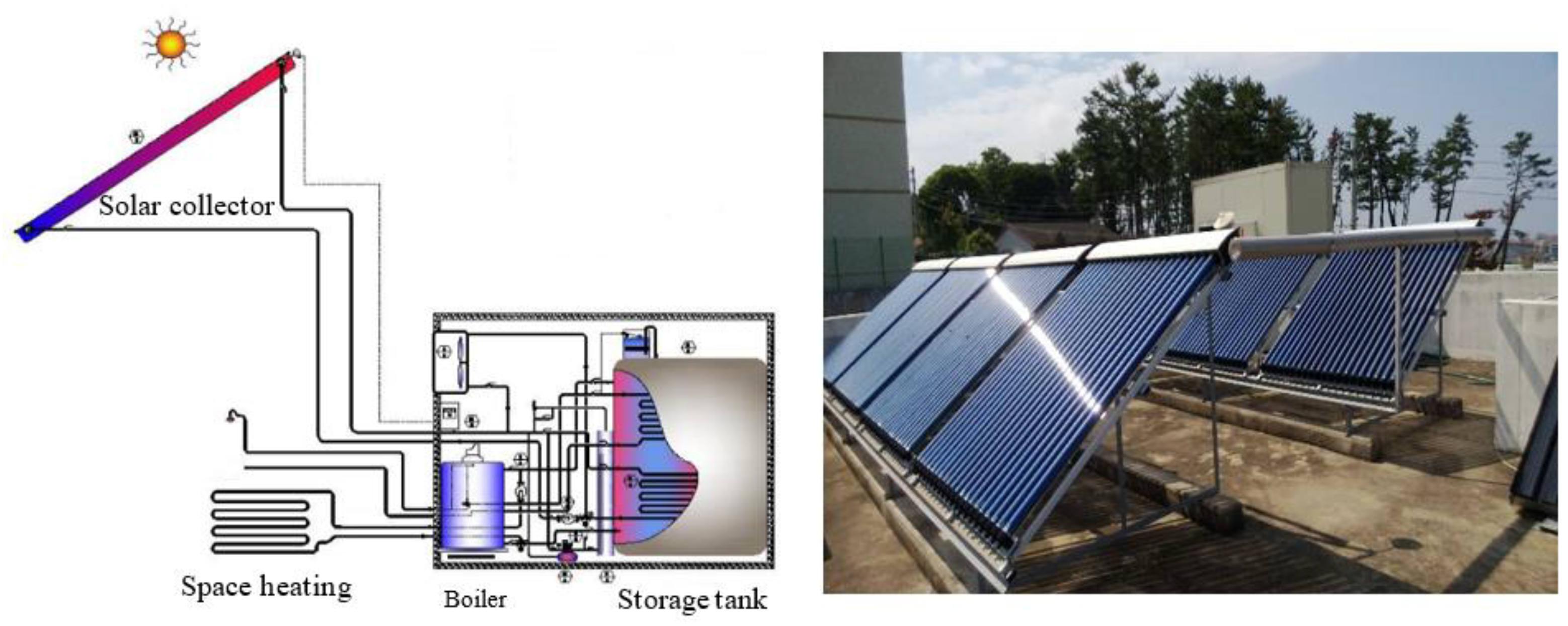
The reference solar-assisted house heating system is presented in Figure 1, which is designed and installed on a Jeju Island home’s rooftop. The latitude, longitude, and altitude of Jeju Island are 33°31′ North, 126°32′ East, and 8 m elevation above the sea level. This system comprises an evacuated tube collector, has a total collection surface area of 26 m2 and was installed with a 45° tilt angle with respect to the horizontal plane towards the south, a thermal storage tank of 1.2 m3, an auxiliary boiler, and the heating panels, as shown in Figure 1. In this reference system, via the heat exchanger in the collector loop, the useful heat gain from the evacuated tube collectors is conveyed by the solar collector to the storage tank. In the case of hot water in the home, if the exit temperature does not hit the required temperature it is heated by the boiler and provided to the user. In the case of space heating, the hot water in the storage tank is delivered through the panels hidden in each room’s floor spaces. When the hot water temperature is adequately high, the energy is extracted from the thermal storage tank; conversely, if the hot water temperature is lower than the appropriate temperature, the boiler is turned on, and hot water is supplied straight to the panels. For the auxiliary boiler, the fuel is kerosene, and the boiler efficiency is assumed to be 80%. The fuel density is 0.839 kg/m3 and the lower heating value is 42,886 kJ/kg.
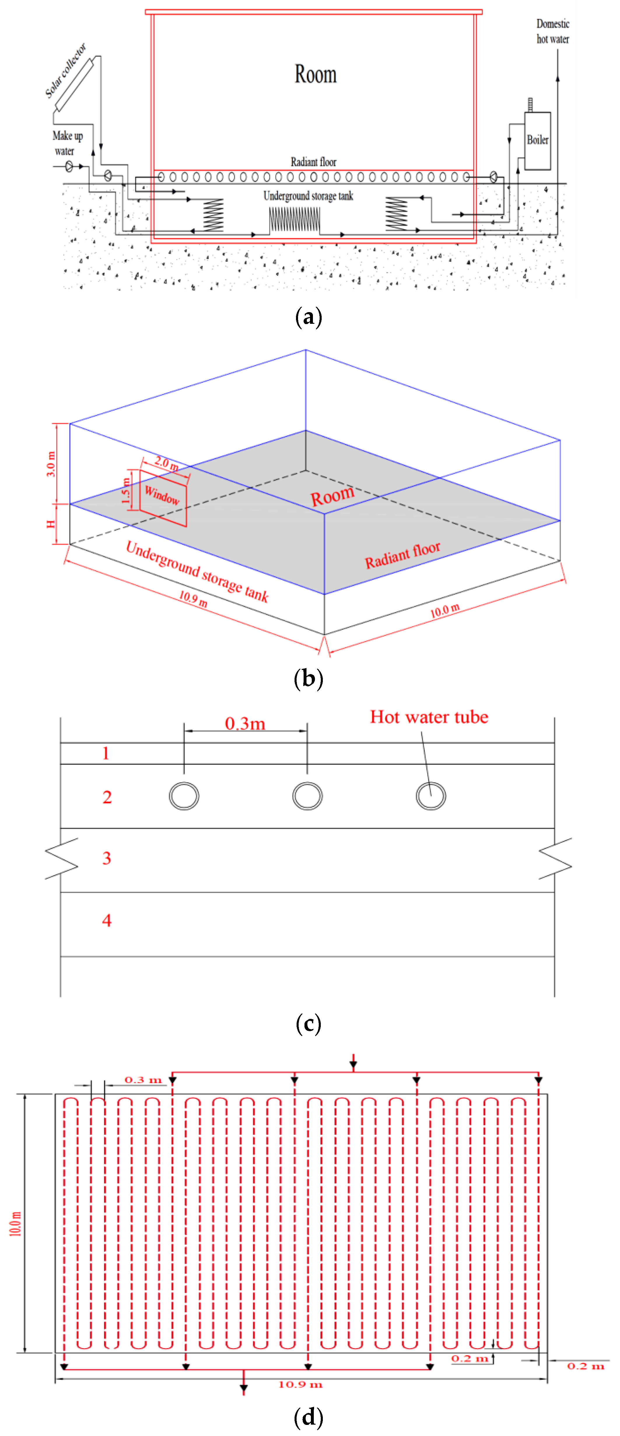
The general view of the proposed and investigated system for a residential house based on the reference solar assisted house heating system is shown in Figure 2. The operation of this system is as follows. The water temperature in the SUTEST is maintained at a minimum value of 50 °C to ensure space heating supply, even during the daytime and for domestic hot water with low solar radiation. Depending on the desires of residential proprietors, four different approaches were designed in the present study. The first loop is the heat addition in which the captured solar energy is transmitted from the solar collector to the SUTEST through the heat exchanger in the collector loop since the tank temperature is much lower than the outlet temperature of the solar collector. The second loop is the heat extraction, an open-loop for domestic water supply used to get thermal energy from the SUTEST and deliver it to users. The required domestic hot water temperature is fixed at 45 °C. In the third loop, the heat addition takes place such that the boiler transfers heat from the combustion process of fuel to the working fluid (water). The working fluid is then pumped to the SUTEST via the heat exchanger in the boiler loop. The boiler loop pump switched on since the SUTEST temperature is less than the set value of 50 °C. The fourth mode is the heat being taken out, actually an open loop that considers the working fluid delivered to the house to remove thermal energy from the UTEST. The heat is transferred via radiant floor heating (tubes with hot water buried inside the floor) to the house. Working fluid is responsible for transferring thermal energy as loops (see Figure 2a).
The SUTEST is built underground to insulate the tank for a somewhat more reliable and less intense cold season as per underground conditions. Also, the temperature of the soil remains constant year-round. The cubic shape is constructed of concrete walls with polyurethane insulation. Figure 2b showed the dimensions of the walls and window. The house is composed of walls, a roof, a window, and a radiant floor. The walls consist of four layers of materials: an internal layer of 20 mm gypsum wallboard, the second layer of 50 mm mineral fiber batt insulation, the third layer of 100 mm concrete, and an external layer of 10 mm cement mortar. The window consists of three layers of materials, an internal layer of 15 mm glass, the second layer of 12.7 mm air (cavity layer), and an external layer of 15 mm glass. The house’s base length, width, and height are 10.9 m, 10 m, and 3 m, respectively. The base width and the height of the window are 2.0 m and 1.5 m, respectively. The floor consists of four layers of materials: a surface layer of 10 mm wood, the second layer of 10 mm cement mortar, the third layer of 100 mm insulation (mineral fiber batt), and a bottom layer of 100 mm concrete; the area of the floor is 109 m2. The four layers of materials and the radiant floor are illustrated in Figure 2c. The tubes are embedded in the cement mortar slabs. To distribute the temperature uniformly and create a comfortable environment for the occupants, the tubes are divided into four branches, illustrated in Figure 2d. The mass flow rate of each branch is set to about 2.0 kg/s. A total tube length of 345.6 m, outer tube diameter of about 0.03 m, thickness of 0.003 m, and tube spacing of about 0.3 m are chosen. Materials’ thermal properties details are given in Table 1.
2.2. Calculation/Theory
2.2.1. Solar Collector
The useful heat gain Qu of the ETC is calculated as provided by [33] as follows:
where m and Ac are the water flow rate and the aperture area of the ETC, respectively. It is the solar radiation on the surface of the ETC and is the cover transmittance absorptance. Tci, Tco and Ta are the inlet and outlet water temperature of the evacuated tube collector and the ambient temperature. UL is the overall heat loss coefficient of the collector.
The collector heat removal factor FR, which is related to the collector area, overall heat loss coefficient, and mass flow rate is determined as:
where F’ and m are the collector efficiency factor and mass flow rate of water in the collector loop.
2.2.2. Seasonal Underground Thermal Storage Tank
An energy balance on the seasonal underground thermal storage tank (SUTEST) is expressed as:
where Qbol and QW are the heat of boiler transfer to the SUTEST and the heat delivered from the SUTEST to the user. Qst-hl and Qpanel are the heat loss of the SUTEST and the radiant floor’s heat, respectively. ; M and cp are the volume and the specific heat of the water in the SUTEST, respectively. Ts is the temperature of water in the SUTEST.
2.2.3. Residential House
The heat balance model for a residential house can be viewed as four distinct processes: the outside surface heat balance, the wall conduction process, the inside surface heat balance, and the air heat balance. This section will describe in detail heat transfer processes for a residential house.
Outside Surface Heat Balance
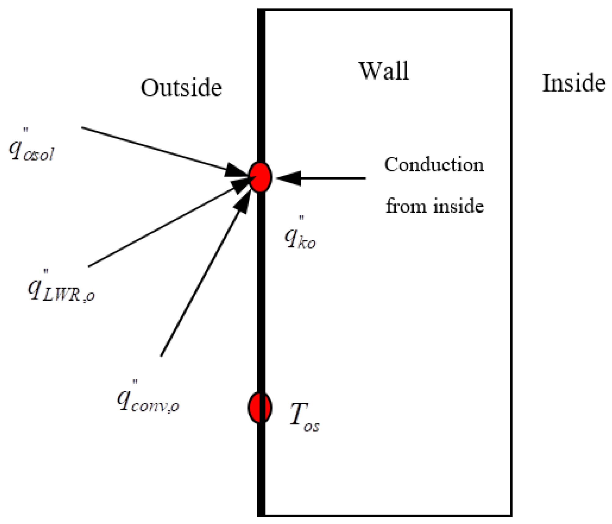
The outside surface heat balance for opaque surfaces consists of four heat transfer processes: net longwave radiation from the environment, convection heat transfer between exterior surface and outside air, short wave radiation, and conduction of the element. These heat transfer components are indicated as in Figure 3, and the outside surface heat balance is expressed as:
where and are absorbed direct and diffuse solar radiation heat flux, and net longwave radiation is absorbed from surroundings. and are convective heat flux exchange with outside air and conduction heat flux on the outside surface, respectively.
Wall Conduction Process
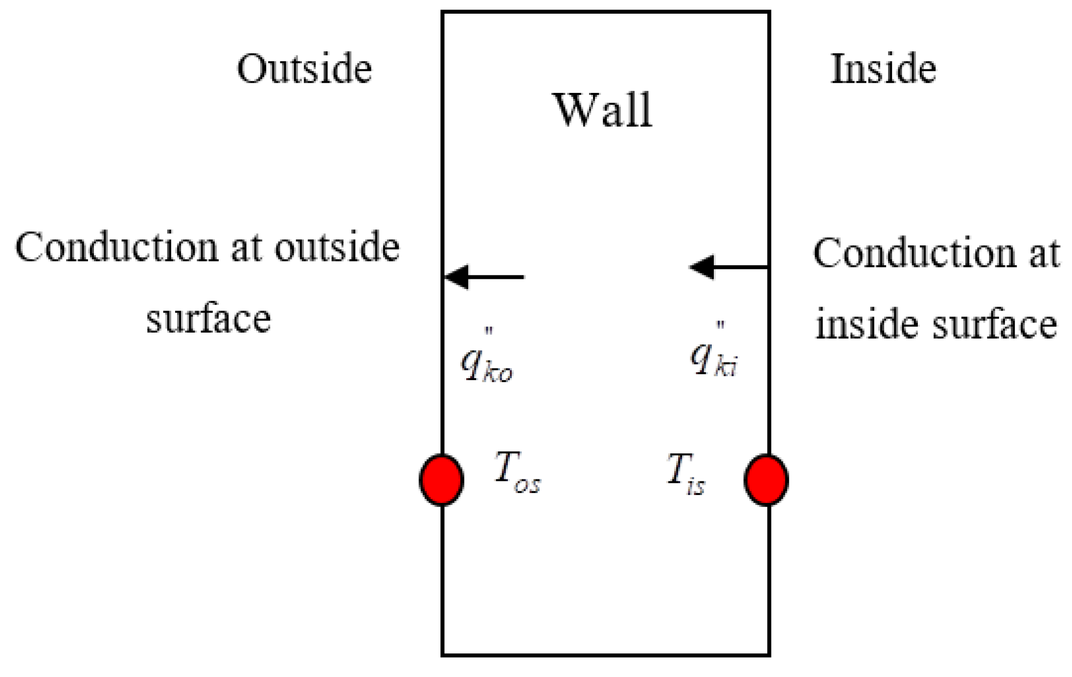
The heat conduction process through building walls is shown graphically in Figure 4, and are the conduction heat fluxes at the inside and outside surface, and Tsi and Tos are the surface temperatures on the inside and outside of the wall. For building heating load calculation, it must be assumed that the wall conduction process through multilayer constructions functions as a one-dimensional transient process. Each layer material is homogeneous, isotropic, and has constant thermal properties (i.e., and ).
The most current thermal load calculation methods of building constructions are the transfer function method, the heat balance method, the radiant time series method, and the thermal response factor method. In this study, the thermal response factor method is used as the method of choice for calculating heating loads. The Equation for heat conduction in a layer of building material is given as follows [34,35,36,37,38,39,40]:
T is the temperature at position (x) and time (t), and α is the layer material’s thermal diffusivity. The heat flux at an arbitrary position x and time t based on Fourier’s of conduction is given as:
where K is the thermal conductivity of the layer material (W/mK).
The solution of Equations (5) and (6) can be represented in terms of Laplace variable s relates the heat flows and temperatures at both surface of the wall as:
The Equation (7) can be re-written based on relating surface temperatures and heat flows of both surfaces as follows:
where GX(s), GY(s), GZ(s) and are the transfer functions of outside, cross, and inside heat conduction of construction, respectively.
The outside surface heat flux for time t in terms of current and past boundary temperatures as inputs and the response factors is expressed as:
and for the inside surface heat flux is as follows:
Xj, Yj, and Zj are external response factors, cross-response factors, and internal response factors.
Heat Balance of Inside Surface
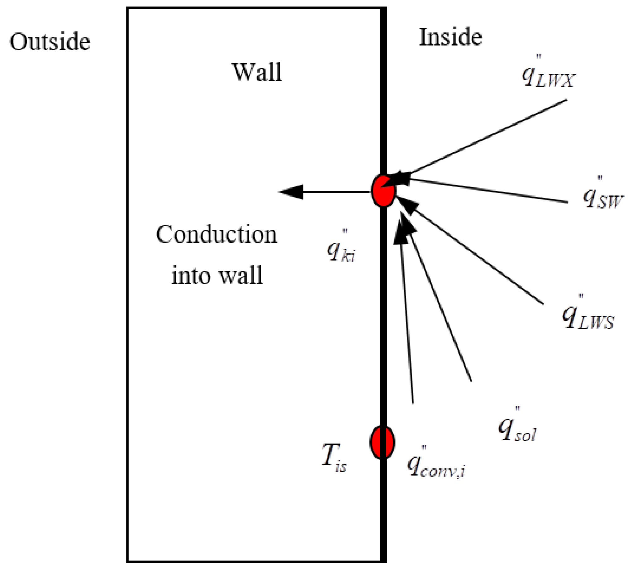
The inside heat balance consists of four heat transfer components: wall conduction, convection from air zone to the inside surface, short wave radiation, and longwave radiant interchanger. These four components are shown schematically in Figure 5. The inside heat balance for each surface is expressed as:
Where , , and are net longwave radiation from zone surfaces, net short-wave radiation from lights, and net longwave radiation from equipment in the zone. and are transmitted solar radiation absorbed by zone surface and convective heat flux from the air zone to the inside surface.
Room Air Heat Balance
The room air heat balance consists of four heat transfer components: convection from zone air to inside surfaces, transport of outside air directly into the zone by infiltration and ventilation, convection heat transfers from internal sources, and heat transfer rate due to the heating panel. The room air heat balance is calculated as follows:
where and are heat capacity of air in the room and convection heat transfer from the room air to the inside surfaces. and are heat transfer from internal sources, i.e., people, lights, equipment, etc., and heat gain due to infiltration.
Based on the calculated overall heat transfer coefficient, the heat flux through the radiant floor is calculated as follows:
where Tpi and Tr are the inlet water temperature of the radiant floor and room air temperature. mp and Up are the mass flow rate of water through the radiant floor and overall heat transfer coefficient of the radiant floor.
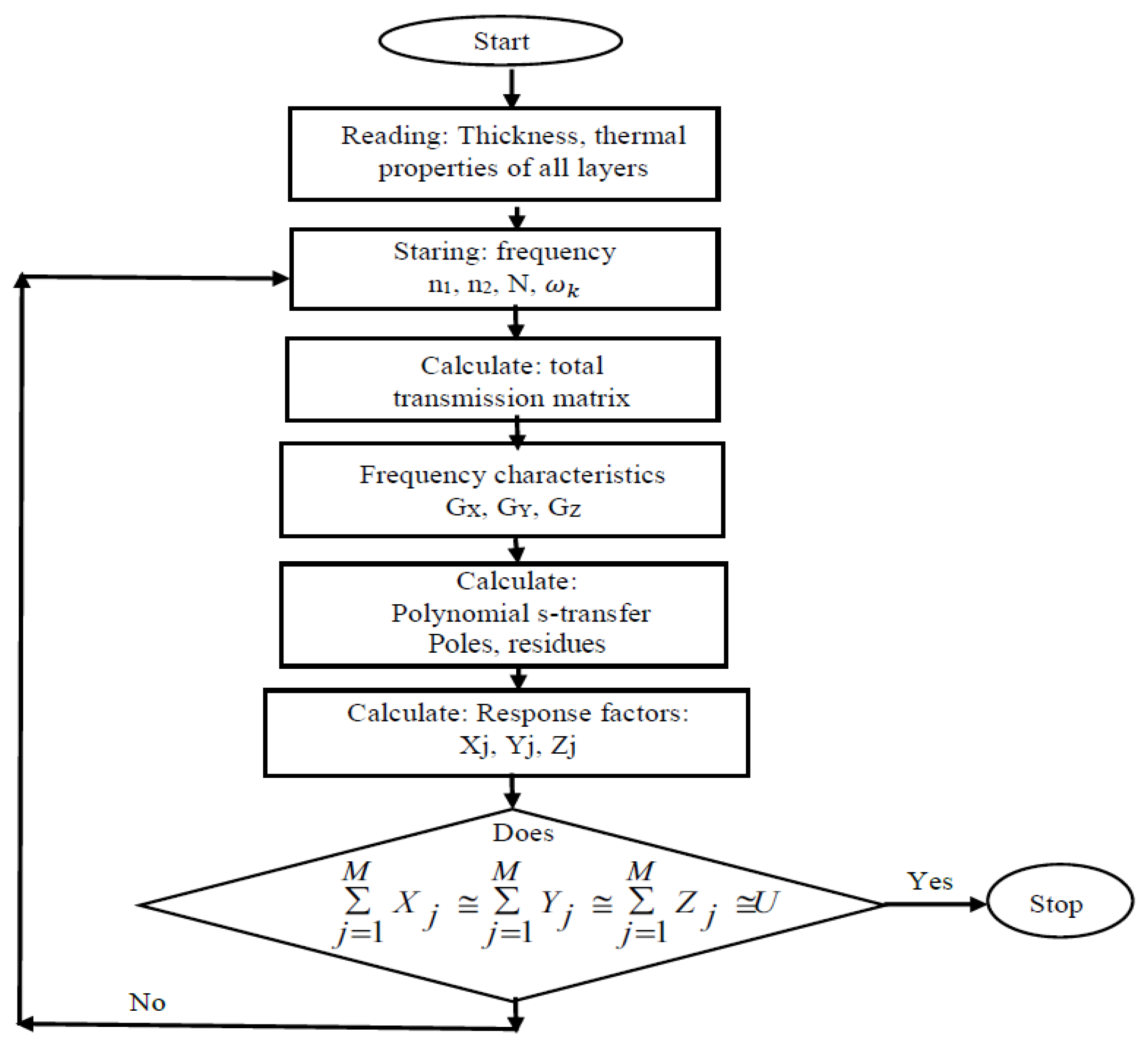
A MATLAB code with a derived mathematical model was developed in this work to calculate the multilayer thermal response factors for a residential house. The flow charts of the calculation program are shown in Figure 6 and Figure 7, respectively. To perform this calculation, the accurate selection of frequency points is essential. It is necessary to determine the number of N frequency points and the required frequency range [10−n1/s, 10−n2/s]. In general, n1 = 7 ÷ 10, n2 = 2 ÷ 4 and N = 10 × (n1˗ n2) + 1. However, the values of n1, n2, and N can be changed depending on materials such as lightweight materials, medium-weight materials, and heavyweight materials. To expand the computation accuracy, the frequency features from the N1th ~ N2th frequency point within the N frequency points are carefully chosen to create the polynomial s-transfer functions, where N1 ≥ 1 and N2 ≤ N. Throughout the calculation process, the values of N1 and N2 are adjusted until the computation precision is not further enhanced. The coefficients of polynomial s-transfer functions change with the difference of parameters n, m, n1, n2, N1, N2. In order to check whether the multilayer thermal response factors constructions are accurate or not, it is important to consider whether the U-factor of multilayer constructions is equivalent to the sum of its thermal response factors used in equation (14).
The 5th order polynomial s-transfers, GX(s), GY(s), GZ(s) for the outside conduction of heat, across heat conduction, and inside heat conduction of the walls, roof, window, and SUTEST were functioned by the frequency domain regression (FDR) process. Thermal response factors of the walls, roof, window, and SUTEST, which were calculated based on polynomial s-transfers GX(s), GY(s), GZ(s) are given in Table 2. In addition, the values of n1, n2, and N, the error percentage (EP) concerning the U-factor, and the total thermal response factors of the outside heat conduction, across heat conduction, and inside heat conduction are also given as in Table 2.
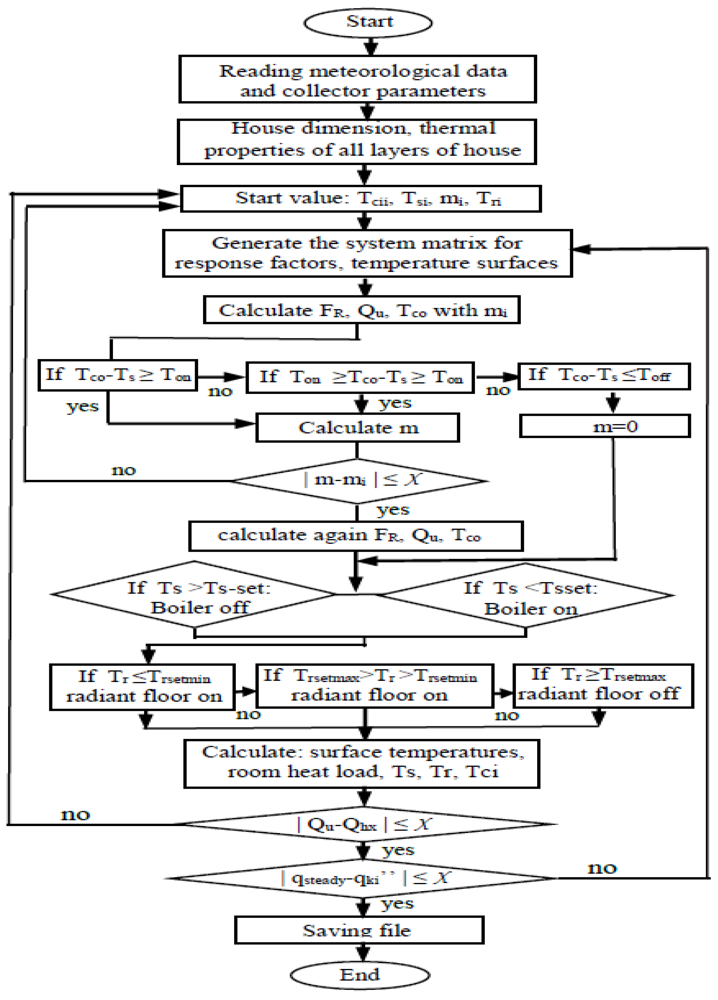
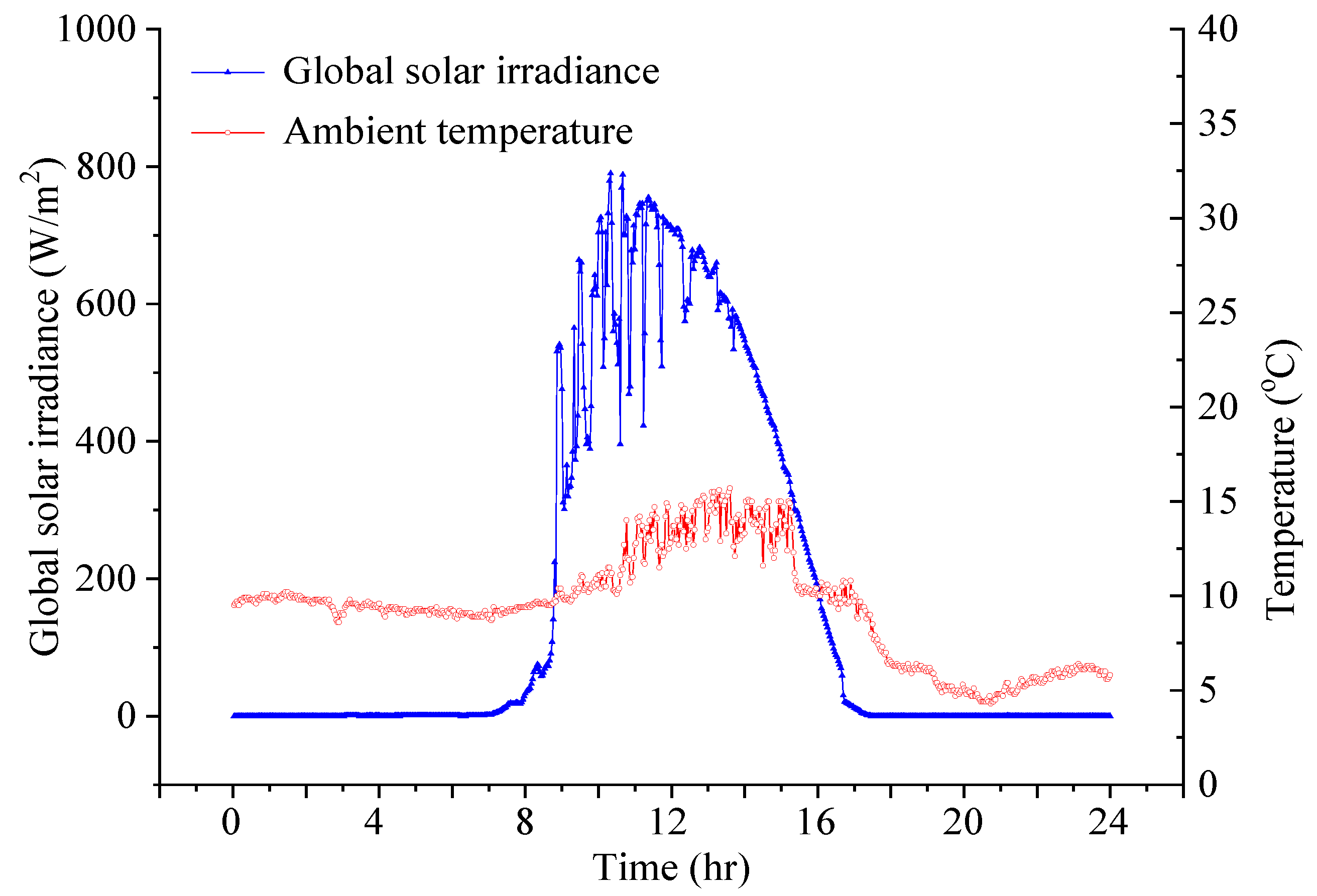
The initial inlet temperature values of collector Tci are the same as the ambient temperature Ta. In the underground thermal storage tank, the initial water temperature value Tsi is 50 °C. The initial mass flow rate value is considered as 0.05 kg/s. The connecting pipe heat loss between the underground thermal storage tank and the radiant floor is neglected. Therefore, the underground thermal storage tank’s water temperature is similar to the inlet temperature of the radiant floor. The bottom surfaces and the side of the radiant floor are correctly insulated. The initial temperature of the house is 22.9 °C. The inside surface convection coefficients of the house are constant. They were chosen to be 4.6 W/m2K for walls, 1.5 W/m2K for the roof, and 6 W/m2K for the floor, respectively. The adjacent ground of the storage tank is expected to have the same configuration and constant thermo-physical characteristics. The ground temperature was chosen to be 16.5 °C. There are no internal heat sources or domestic hot water supply to the user. The simulation was performed with the time step of 120 s. This is the smallest time step that can be satisfied with the convergence requirement of Equation (14). The simulation input on whether findings consist of global solar irradiance and ambient temperature is shown in Figure 8. In this simulation, the heat stabilities expressed concerning response factors that are solved for each time of the day. The solution method may be iterative (initial guess of the surface temperatures and heat fluxes are updated until they converge). A check on the solution validity is obtained by solving a steady-state problem Equation (15).
3. Results and Discussion
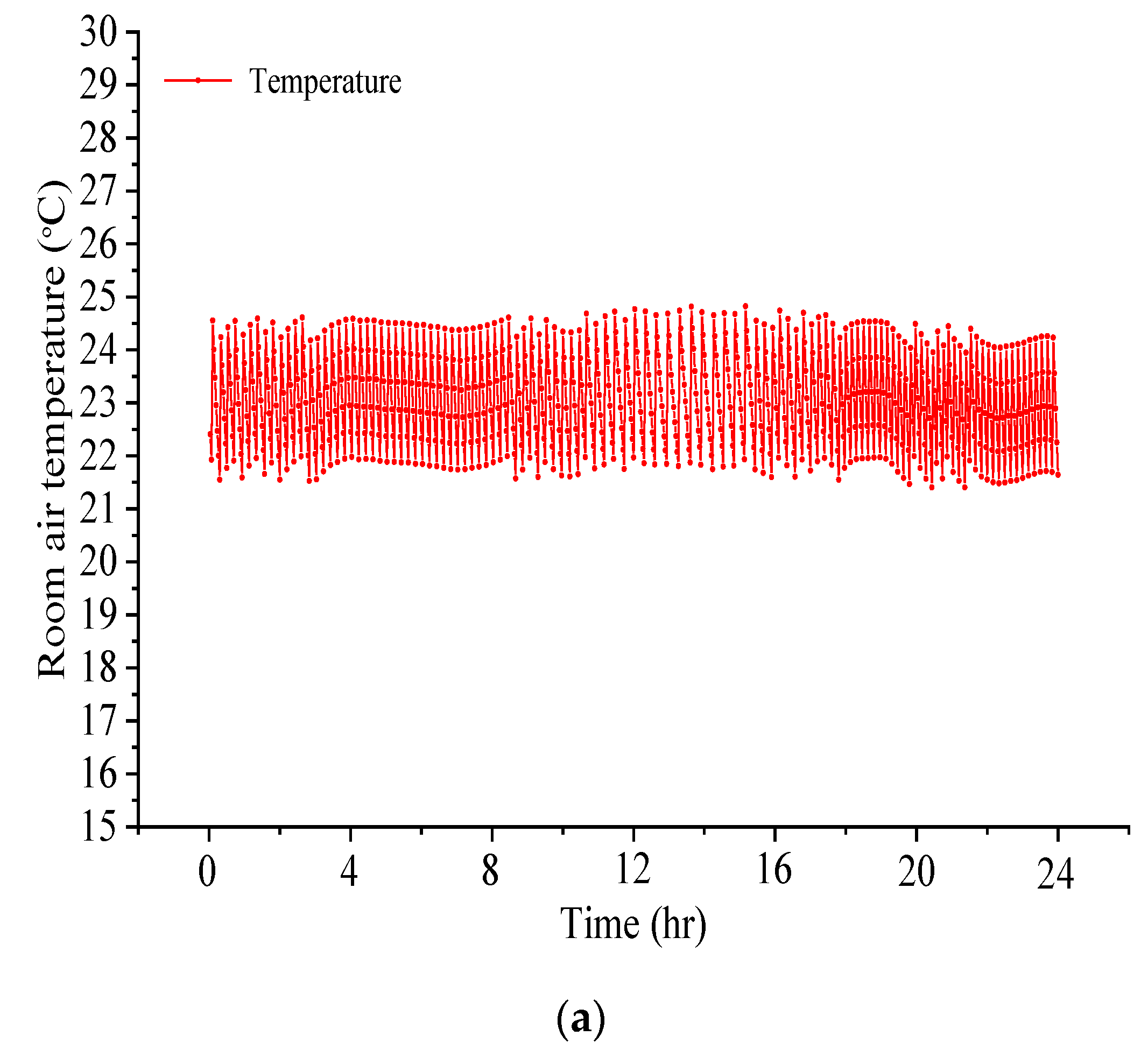
To satisfy the occupants’ comfort and health, the minimum room temperature was set to be 22 °C whereas the maximum room temperature was set to be 25 °C. This means that the room air temperature was retained between 22 °C to 25 °C. On the other hand, an easiness dead band is set from 22 °C to 25 °C to create a hysteresis heating cycle. The control procedure of the radiant floor is simple. The pump of the radiant floor loop was based on the sensor signal, this sensor was mounted inside the room. The radiant floor loop pump is switched on when the room air temperature fell below 22 °C and remains on until the room air temperature reaches 25 °C, at which point it will be switched off. If the temperature decreases below 22 °C, a fresh cycle begins. The oscillation of the room air temperature during the day is shown in Figure 9a. As indicated in Figure 9a, the room air temperature intensely oscillated between 00:00 and 08:30, and then slowly oscillated until about 16:30 and then strongly oscillated until about 24:00. This is due to the oscillating of the ambient temperature leading to the change of the heat load of the room.
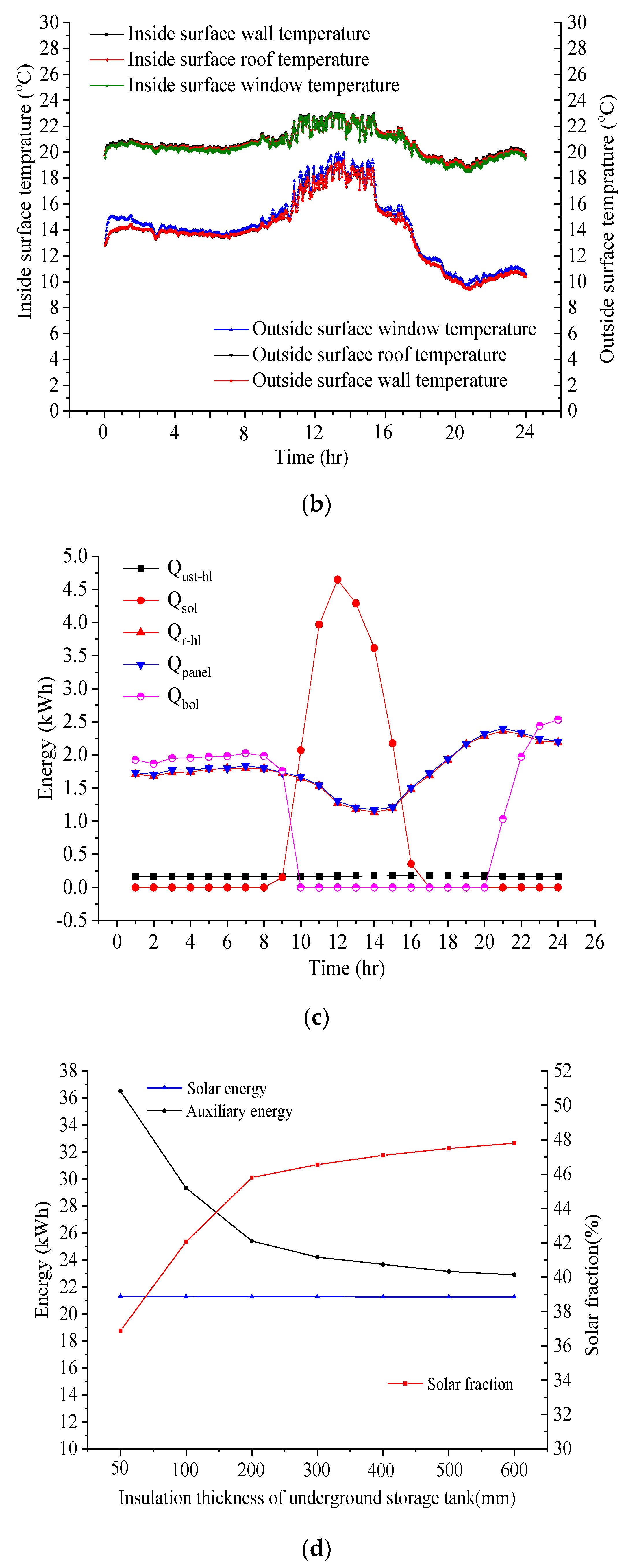
Figure 9b describes the temperature oscillation of the outside surfaces and inside surfaces of the room during the day. As seen in Figure 9b, the dissimilarity between the inside surface temperatures and, the room air temperature ranges from 0.5 °C to 2 °C, while the variations regarding the temperature of the outside surfaces and the ambient temperature range from 2 °C to 5 °C. This difference strongly decreased from 09:00 to 16:00, and the increased ambient temperature led to the room’s heat capacity decreasing. The temperature oscillation of the surfaces is not the same. This is due to the surfaces of the room having a convection coefficient, and different building materials.
Figure 9c shows the solar-assisted heating system heat transfer trend for the residential houses during the day. In this work, an underground thermal storage tank is 10 m3 and is built of concrete with polyurethane insulation of 200 mm were taken into consideration. The useful heat gains heat flux of the solar collector is conveyed to the underground thermal storage tank. From 09:00 to 16:00 the auxiliary heat flux of the boiler was transported to the underground thermal storage tank during 00:00 to 09:00 and from 21:00 to 24:00. The radiant floor heat flux supplied into the room slightly changed between 00:00 and 08:30, decreased slowly until about 15:00, and then increased again. This is because of the change in ambient temperature and the fluctuation of the global solar irradiance, leading to the change of the room’s heat load . The heat flux of the heat loss of the underground thermal storage tank slightly changed. That is because the ground temperature is constant, and the water temperature in the underground thermal storage tank slightly changed during the day. The solar fraction is usually used to measure the solar heating system’s efficiency, which means the fraction of the total heating capacity provided by the sun. The valuable heat gain amount of the solar collector, the auxiliary heat amount of the boiler, the heat amount of the radiant floor , the heat load of the room , the heat loss amount of the underground thermal storage tank, and the solar fraction for during the day are given in Table 3.
Figure 9d shows the effect of the underground thermal storage tank′s insulation thickness on system effectiveness throughout the day. When the insulation thickness ranges from 50 mm to 200 mm, the amount of extra energy sharply decreases from 36.5 kWh to 25.41 kWh, the useful heat gain decreases only slightly, and the solar fraction strongly increases from 36.89% to 45.8%. This is because the increase in insulation thickness leads to a decrease in the underground thermal storage tank’s heat loss. When the insulation thickness grows larger than 200 mm, the amount of auxiliary energy continued to decrease, but at a much lower rate, the useful heat gain continued to slightly decrease, and the solar fraction tends to be steady. This is because the increase in water temperature is lower than the increase in the U-factor of the underground thermal storage tank, while the heat loss of the underground thermal storage tank decreases slowly.
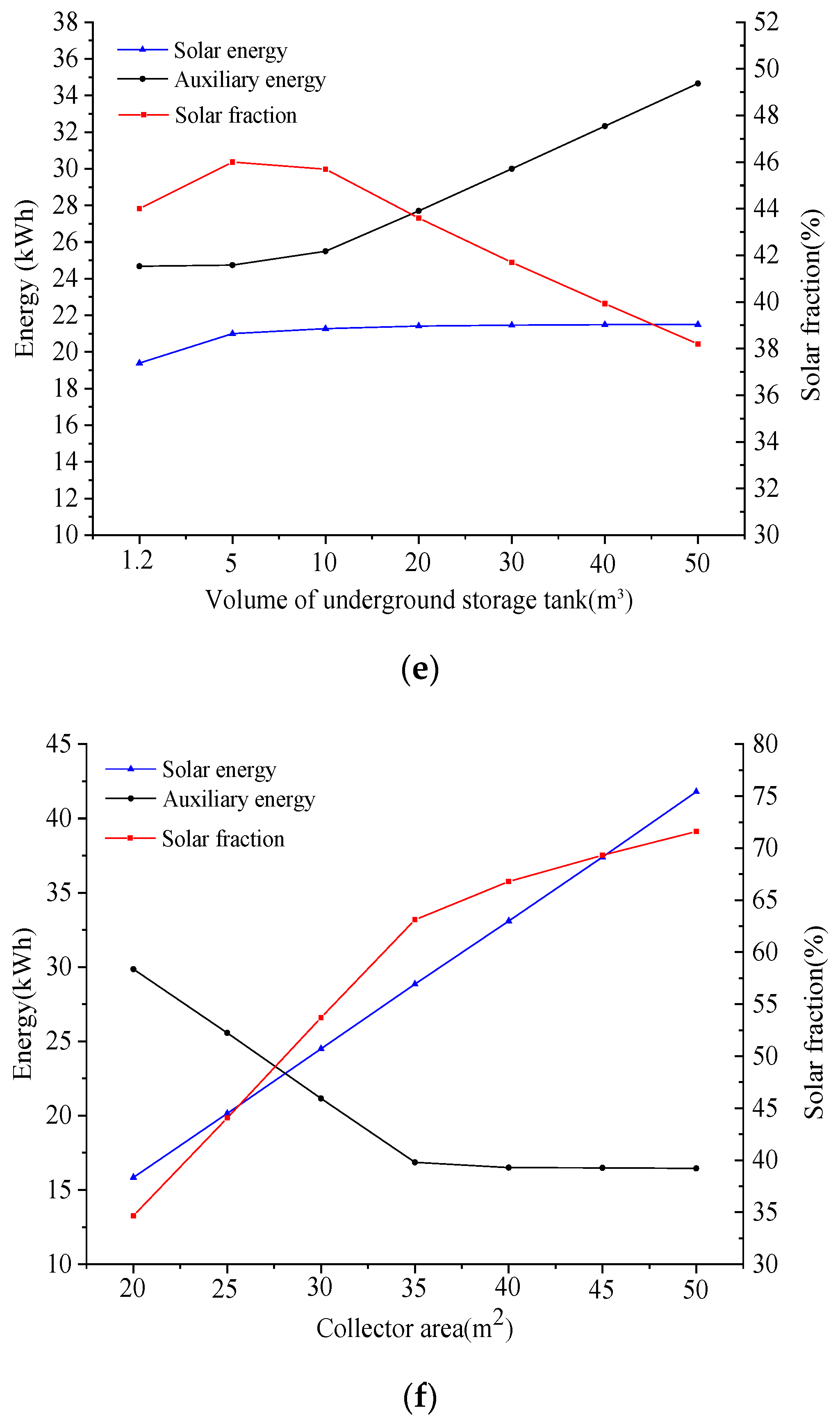
Figure 9e shows the effect of the underground thermal storage tank’s volume on system performance during the day. When the underground thermal storage tank volume ranges from 1.2 m3 to 5 m3, the amount of auxiliary energy slightly increases, the useful heat gain increases from 19.39 kWh to 21 kWh, and the solar fraction sharply increases from 43.9% to 46.1%. For tank volume sizes from 5 m3 to 50 m3, the number of auxiliary energies increases gradually until about 10 m3 and then increases sharply, while the useful heat gain tends to be steady. The solar fraction slightly decreases until about 10 m3 and then strongly decreases. This is because the collector remains the same while the underground thermal storage tank volume increases. At the underground thermal storage tank, 1.2 m3 did not have enough thermal mass to store as much useful heat gain as the larger underground thermal storage tank. The tanks 5 m3 and larger were able to store more useful heat gain transferred to the room via the radiant floor.
The room model with an underground thermal storage tank 5 m3 could supply more heat to the room via the radiant floor, which lowers the sum of heat delivered by the supporting boiler. However, once the underground thermal storage tank’s volume increased above 5 m3, the quantity of heat delivered by the supporting boiler increased. This can be explained by the required temperature of water in the underground thermal storage tank not being less than 50 °C. Therefore, the volume increase leads to an increase in the storage mass, and more energy is required to maintain this temperature. Thus, although the 50 m3 tank can constitute the total stored energy, the temperature of that larger tank is not as high. Therefore, further increases in tank size were not advantageous. The large volume of the underground thermal storage tank is meaningful only when a large solar collector area accompanies it.
Figure 9f demonstrates the solar collector area’s consequences on system efficiency throughout the day. Once the collector area ranges from 20 m2 to 35 m2, the amount of auxiliary energy strongly decreases from 29.86 kWh to 16.86 kWh, the useful heat gain increases from 15.84 kWh to 28.85 kWh, and the solar fraction sharply increases from 34.66% to 63.12%. This is because the greater the area of collectors, the more significant the amount of useful heat gain that can be captured, stored, and distributed into the room. When the collector area grows more massive than 35 m2, the number of auxiliary energies tends to be steady, while the useful heat gain continued to upsurge and the solar fraction slowly increases. This is due to the simulation calculated during the day. Therefore, in the earlier morning, the energy amount required to maintain the underground thermal storage tank’s water temperature is not less than 50 °C, so this energy was provided by the auxiliary boiler. However, after that period, it was provided by the useful heat gain of the solar collectors.
4. Conclusions
In the present study, the solar-assisted heating system for a residential house with a seasonal underground thermal storage tank is developed, and the following conclusion could be obtained. This work proposes a solar-assisted heating system for a residential house with SUTEST, in which the heat load of the house and heat loss of the SUTEST were evaluated by the thermal response factor method. A MATLAB program was developed, depending on the basic mathematical model to compute the thermal response factors. The polynomial s-transfers of building construction were also estimated.
The optimal insulation thickness of SUTEST should be better or equal to 200 mm. This ensures the highest solar fraction. The optimal volume of the SUTEST was determined at 5 m3. This work also demonstrated that the large volume of the underground thermal storage tank is meaningful only when a large solar collector area accompanies it. For this study, we recommend that a residential house’s solar-assisted heating system with a thermal storage tank should be replaced by the solar-assisted heating system with a boiler and a SUTEST. This will become the cause of the rise in solar fraction and a decrease in SUTEST heat loss.
The simulations were performed on dissimilar days in terms of weather conditions, i.e., a clear day, intermittently cloud sky, and overcast sky to calculate the system operation with a constant mass flow rate for the collector loop. The simulated results showed that the obtained solar fraction was 45.8%, 17.26%, and 0%.
Author Contributions
Methodology, validation, formal analysis, investigation, L.M.N. Writing—original draft preparation and writing—review and editing, W.R.; supervision, funding acquisition, and project administration, Y.C.P. All authors have read and agreed to the published version of the manuscript.
Funding
The technology innovation program supported this work (No. 20182020109700, development of a hybrid cooling system for refrigeration truck with an ejector) funded by the Ministry of Trade, Industry and Energy (MOTIE, Korea), by the National Research Foundation of Korea (No. 2020R1A2C1011871), and by the project of 2021 funded by Ho Chi Minh City University of Technology and Education, Ho Chi Minh City, Vietnam.
Conflicts of Interest
The authors declare no conflict of interest.
Nomenclature
| Ac | Aperture area of collector (m2) |
| Cp | Specific heat (J/kg. K) |
| Cair | Heat capacity of air in the room (J/K) |
| FR | Collector heat removal factor |
| It | Solar radiation (W/m2) |
| K | Thermal Conductivity (W/mK) |
| L | Thickness (mm) |
| N | Number of frequency points |
| M | Volume of water in the SUTEST (m3) |
| m | Mass flow rate of collector loop (kg/s) |
| mp | Mass flow rate of the radiant floor (kg/s) |
| Qbol | Heat of boiler (W) |
| Qpanel | Heat of radiant floor (W) |
| Qr-hl | Room heat load (W) |
| Qu | Useful solar heat gain (W) |
| Qust-hl | Heat loss of storage tank (W) |
| Convection heat transfer from the room air to the inside surfaces (W) | |
| Heat transfer from internal sources, i.e., people, lights, equipment, etc. (W) | |
| Heat gain due to infiltration (W) | |
| Absorbed direct and diffuse solar radiation heat flux (W/m2) | |
| Net longwave radiation absorbed from surroundings (W/m2) | |
| Convective heat flux exchange with outside air (W/m2) | |
| Outside surface heat flux (W/m2) | |
| Inside surface heat flux (W/m2) | |
| Net longwave radiation from zone surfaces (W/m2) | |
| Short wave radiation from lights (W/m2) | |
| Net longwave radiation from equipments in zone (W/m2) | |
| Transmitted solar radiation absorbed by zone surface (W/m2) | |
| convective heat flux from the air zone to inside surface (W/m2) | |
| R | Resistance (m2K/W) |
| TES | Thermal energy storage |
| STES | Seasonal thermal energy storage |
| SUTEST | Seasonal underground thermal energy storage tank |
| UTEST | Underground thermal energy storage tank |
| Ta | ambient temperature (°C) |
| Tis | Inside surface temperature (°C) |
| Tos | Outside surface temperature (°C) |
| Tci | Collector inlet temperature (°C) |
| Tco | Collector outlet temperature (°C) |
| Ts | Temperature of water in the SUTEST (°C) |
| Tsi | Storage tank inlet temperature (°C) |
| Tr | Room air temperature (°C) |
| Tpi | Inlet water temperature of the radiant floor (°C) |
| UST | Underground storage tank |
| UL | overall heat loss coefficient of the collector (W/m2K) |
| Up | overall heat transfer coefficient of the radiant floor (W/m2K) |
| ρ | Density of water (kg/m3) |
| cover transmittance absorptance |
References
- OECD/IEA. Transition to Sustainable Buildings. Strategies and Opportunities to 2050, (2013) 31. Available online: https://www.iea.org/publications/freepublications/publication/Building2013_free.pdf (accessed on 8 July 2020).
- Buker, M.S.; Riffat, S.B. Solar assisted heat pump systems for low temperature water heating applications: A systematic review. Renew. Sustain. Energy Rev. 2016, 55, 399–413. [Google Scholar] [CrossRef]
- Kamel, R.S.; Fung, A.S.; Dash, P.R.H. Solar systems and their integration with heat pumps: A review. Energy Build. 2015, 87, 395–412. [Google Scholar] [CrossRef]
- Wang, H.; Qi, C.; Wang, E.; Zhao, J. A case study of underground thermal storage in a solar-ground coupled heat pump system for residential buildings. Renew. Energy 2008, 34, 307–314. [Google Scholar] [CrossRef]
- Gallo, A.B.; Simoes-moreira, J.R.; Costa, H.K.M.; Santos, M.M.; Moutinho, E. Energy storage in the energy transition context: A technology review. Renew. Sustain. Energy Rev. 2016, 65, 800–822. [Google Scholar] [CrossRef]
- Wang, H.; Zhao, J. Center solar heating technology with seasonal thermal storage. Sol. Energy 2005, 108, 27–31. [Google Scholar]
- Novo, A.V.; Bayon, J.R.; Castrro-Fresno, D.; Rodriguez-hernandez, J. Review of seasonal heat storage in large basins: Water tanks and gravel-water pits. Appl. Energy 2010, 87, 390–397. [Google Scholar] [CrossRef]
- Thomsen, P.D.; Overbye, P.M. Energy storage for district energy systems. In Advanced District Heating and Cooling (DHC) Systems; Wiltshire, R., Ed.; Woodhead Publishing: Oxford, UK, 2016; pp. 145–166. [Google Scholar]
- Soarknaes, P. Simulation method for a pit seasonal thermal energy storage system with a heat pump in a district heating system. Energy 2018, 152, 533–538. [Google Scholar] [CrossRef]
- Dincer, I. Thermal energy storage systems as a key technology in energy conservation. Int. J. Energy Res. 2002, 26, 567–588. [Google Scholar] [CrossRef]
- Dincer, I. On thermal energy storage systems and applications in buildings. Energy Build. 2002, 34, 377–388. [Google Scholar] [CrossRef]
- Inalli, M.; Unsal, M.; Tanyildizi, V. A computational model for a solar heating system with underground thermal spherical storage. Energy 1997, 22, 1163–1172. [Google Scholar] [CrossRef]
- Ucar, A.; Inalli, M. A thermos-economical optimization of a domestic solar heating plant with seasonal storage. Appl. Eng. 2007, 27, 450–456. [Google Scholar] [CrossRef]
- Nordell, B.; Hellstrom, G. High temperature solar heated seasonal storage system for low temperature heating of building. Sol. Energy 2000, 69, 511–523. [Google Scholar] [CrossRef]
- Qu, M.; Yin, H.; Archer, D.H. A solar thermal cooling and heating system for a building: Experimental and model based performance analysis and design. Sol. Energy 2010, 84, 166–182. [Google Scholar] [CrossRef]
- Heller, A. 15 Years of R&D in central solar heating in Denmark. Sol. Energy 2000, 69, 437–447. [Google Scholar]
- Lin, W.; Ma, Z.; Ren, H.; Gschwander, S.; Wang, S. Multi-objective optimization of thermal energy storage using phase change materials for solar air systems. Renew. Energy 2019, 130, 1116–1129. [Google Scholar] [CrossRef]
- Bauer, D.; Marx, R.; Nußbicker-Lux, J.N.; Ochs, F.; Heidemann, W.; Muller-Steinhagen, H. German central solar heating plants with seasonal heating storage. Sol. Energy 2010, 84, 612–623. [Google Scholar] [CrossRef]
- Bauer, D.; Marx, R.; Druck, H. Solar district heating for the built environment technology and future trends within the European project Einstein. Energy Procedia 2014, 57, 2716–2724. [Google Scholar] [CrossRef] [Green Version]
- Lundh, M.; Dalenback, J.O. Swedish solar heated residential area with seasonal storage in rock: Initial evaluation. Renew. Energy 2008, 33, 703–711. [Google Scholar] [CrossRef]
- Tao, T.; Zhang, F.; Zhang, W.; Wan, P.; Shen, X.; Li, H. Low cost and marketable operational experiences for a solar heating system with seasonal thermal energy storage (SHSSTES) in Hebei (China). Energy Procedia 2015, 70, 267–274. [Google Scholar] [CrossRef] [Green Version]
- Xu, L.; Torrens, J.I.; Guo, F.; Yang, X.; Hensen, J.L.M. Application of large underground seasonal thermal energy storage in district heating system: A model-based energy performance assessment of a pilot system in Chifeng, China. Appl. Eng. 2018, 137, 319–328. [Google Scholar] [CrossRef]
- Xu, J.; Li, Y.; Wang, R.Z.; Liu, W. Performance investigation of a solar heating system with underground seasonal energy storage for greenhouse application. Energy 2014, 67, 63–73. [Google Scholar] [CrossRef]
- Quintana, H. A Practical Approach to Model Predictive Control (MPC) for Solar Communities. Master’s Thesis, University of Montreal, Montreal, QC, Canada, October 2013. [Google Scholar]
- Catolico, N.; Ge, S.; McCartney, J.S. Numerical modeling of a soil-borehold thermal energy storage system. Vadose Zo. J. 2016, 15, 1–17. [Google Scholar]
- Baser, T.; McCartney, J.S. Transient evaluation of a soil-borehole thermal energy storage system. Renew. Energy 2018, 147, 2582–2598. [Google Scholar] [CrossRef] [Green Version]
- Solar District Heating Guidelines: Storage Fact Sheet. Available online: http://citeseerx.ist.psu.edu/viewdoc/download?doi=10.1.1.456.6216&rep=rep1&type=pdf (accessed on 8 July 2020).
- Villasmil, W.; Fischer, L.J.; Worlitschek, J. A review and evaluation of thermal insulation materials and methods for thermal energy storage systems. Renew. Sustain. Energy Rev. 2019, 103, 71–84. [Google Scholar] [CrossRef]
- Amiri, L.; de Brito, M.A.R.; Baidya, D.; Kuyuk, A.F.; Ghoreishi-Madiseh, S.A.; Sasmito, A.P.; Hassani, F.P. Numerical investigation of rock-pile based waste heat storage for remote communities in cold climates. Appl. Energy 2019, 252, 113475. [Google Scholar] [CrossRef]
- Ochs, F.; Dahash, A.; Tosatto, A.; Janetti, M.B. Techno-economic planning and construction of cost-effective large-scale hot water thermal energy storage for Renewable District heating systems. Renew. Energy 2019, 150, 1165–1177. [Google Scholar] [CrossRef]
- Li, X.; Wang, Z.; Li, J.; Yang, M.; Yuan, G.; Bai, Y.; Chen, L.; Xu, T.; Gilmanova, A. Comparison of control strategies for a solar heating system with underground pit seasonal storage in the non-heating season. J. Energy Storage 2019, 26, 100963. [Google Scholar] [CrossRef]
- Yumrutaş, R.; Ünsal, M. Energy analysis and modeling of a solar assisted house heating system with a heat pump and an underground energy storage tank. Sol. Energy 2012, 86, 983–993. [Google Scholar] [CrossRef]
- Duffie, J.A.; Beckman, W.A. Solar Engineering of Thermal Processes, 3rd ed.; Wiley: Hoboken, NJ, USA, 2006. [Google Scholar]
- Chen, Y.; Wang, S. A new procedure for calculating periodic response factors based on frequency domain regression method. Int. J. Therm. Sci. 2005, 44, 382–392. [Google Scholar] [CrossRef]
- Ciulla, G.; Brano, V.L.; Orioli, A. A criterion for the assessment of the reliability of ASHRAE cinduction transfer function coefficients. Energy Build. 2010, 42, 1426–1436. [Google Scholar] [CrossRef]
- Wang, S.; Chen, Y. A novel and simple building load calculation model for building and system dynamic simulation. Appl. Therm. Eng. 2001, 21, 683–702. [Google Scholar] [CrossRef]
- Li, S.Q.; Chen, Y.; Spiler, J.D.; Fisher, D. Applicability of calculation methods for conduction transfer function of building constructions. Int. J. Therm. Sci. 2009, 48, 1441–1451. [Google Scholar] [CrossRef]
- Rees, S.; Lysebetten, G.V. A response factor approach to modelling long-term thermal behavior of energy piles. Comput. Geotechices 2020, 120, 1033424. [Google Scholar]
- Rasooli, A.; Itard, L. In-situ rapid determination of walls’ thermal conductivity, volumetric heat capacity, and thermal resistance, using response factors. Applied Energy. 2019, 253, 113539. [Google Scholar] [CrossRef]
- Chen, Y.; Pan, B.; Zhang, X.; Du, C. Thermal response factors for fast parameterized design and long-term performance simulation of vertical GCHP systems. Renew. Energy 2019, 136, 793–804. [Google Scholar] [CrossRef]
Figure 1.
Illustration of a reference solar-assisted house heating system.

Figure 2.
Proposed system diagrams. (a) Solar-assisted house heating using an underground thermal energy storage system; (b) House dimension; (c) 1. The surface layer (wood); 2. Cement mortar; 3. Insulation; 4. Concrete)); (d) Radiant floor hot water tube dispositions.
Figure 2.
Proposed system diagrams. (a) Solar-assisted house heating using an underground thermal energy storage system; (b) House dimension; (c) 1. The surface layer (wood); 2. Cement mortar; 3. Insulation; 4. Concrete)); (d) Radiant floor hot water tube dispositions.

Figure 3.
Schematic of outside surface heat balance.

Figure 4.
Schematic of the wall conduction process

Figure 5.
Inside surface heat transfer components.

Figure 6.
Flow chart for thermal response factor calculations.

Figure 7.
Flow chart for the calculation of an underground thermal energy storage system.

Figure 8.
Global solar irradiance and ambient temperature.

Figure 9.
Solar-assisted heating system temperature oscillation and parametric effects. (a) The room air temperature oscillation during the day; (b) The outside surfaces temperature oscillation and inside room surfaces during the day; (c) Solar-assisted heating system heat transfer for a residential house with an underground thermal storage tank; (d) Underground thermal storage tank effect of insulation thickness on system efficiency during the day; (e) Volume effect of underground thermal storage tank on system effectiveness throughout the day; (f) Solar collector area effect on method compactness throughout the day.


Table 1.
Main parameters for calculations.
| Description | The Thickness and Thermal Properties | |||||
|---|---|---|---|---|---|---|
| Thickness L (mm) | Thermal Conductivity K (W/mK) | Density ρ (kg/m3) | Specific Heat Cp (J/kg.K) | Resistance R (m2K/W) | ||
| Roof | Cement mortar | 10 | 0.93 | 1600 | 906 | 0.01075 |
| Concrete | 100 | 1.73 | 2235 | 1106 | 0.05780 | |
| Insulation | 50 | 0.0433 | 32 | 840 | 1.15473 | |
| Air layer | 250 | - | - | - | 0.18 | |
| Gypsum ceiling board | 20 | 0.16 | 641 | 840 | 0.125 | |
| Walls | Cement mortar | 10 | 0.93 | 1600 | 900 | 0.01075 |
| Concrete | 100 | 1.73 | 2225 | 1106 | 0.05780 | |
| Insulation | 50 | 0.0433 | 91 | 840 | 1.15473 | |
| Gypsum wall board | 20 | 0.727 | 1602 | 840 | 0.02751 | |
| Window Double Glazing | Glass | 15 | 0.756 | 2500 | 840 | 0.01984 |
| Air (cavity layer) | 12.7 | - | - | - | 0.18 | |
| Glass | 15 | 0.756 | 2500 | 840 | 0.01984 | |
| Floor | Surface layer | 10 | 0.16 | 700 | 1630 | 0.0625 |
| Cement mortar | 100 | 0.93 | 1600 | 900 | 0.10752 | |
| Insulation | 100 | 0.0433 | 91 | 840 | 2.30946 | |
| Concrete | 100 | 1.73 | 2235 | 1106 | 0.05780 | |
| UST | Cement mortar | 10 | 0.93 | 1600 | 900 | 0.01075 |
| Concrete | 100 | 1.73 | 2235 | 1106 | 0.05780 | |
| Insulation | 200 | 0.0433 | 91 | 840 | 4.61893 | |
| Concrete | 100 | 1.73 | 2235 | 1106 | 0.05780 | |
| CST | Insulation | 206 | 0.0433 | 91 | 840 | 4.75750 |
| Steel | 5 | 45.3 | 7833 | 502 | 1.10374 | |
Table 2.
Thermal response factor of the wall, roof, window, and seasonal underground thermal energy storage tank (SUTEST).
Table 2.
Thermal response factor of the wall, roof, window, and seasonal underground thermal energy storage tank (SUTEST).
| X(s) (W/m2K) | Y(s) (W/m2K) | Z(s) (W/m2K) | Frequency Points N | ||
|---|---|---|---|---|---|
| Wall | ∑ | 0.79949473 | 0.79949720 | 0.79949472 | N = 9 × (n1 − n2) +1 (n1 = 9, n2 = 3) |
| Uwall | 0.79949471 | 0.79949471 | 0.79949471 | ||
| EP | 2.5 × 10⁻⁶% | 3.11 × 10⁻⁴% | 1.25 × 10⁻⁶% | ||
| Roof | ∑ | 0.6543432181 | 0.6543432024 | 0.6543432030 | N= 9 × (n1 − n2) +1 (n1 = 9, n2 = 3) |
| Uroof | 0.6543303583 | 0.6543303583 | 0.6543303583 | ||
| EP | 1.96 × 10⁻³% | 1.96 × 10⁻³% | 1.96 × 10⁻³% | ||
| Window | ∑ | 4.552034304 | 4.550037054 | 4.552034304 | N= 11 × (n1 − n2) +1 (n1 = 6, n2 = 1) |
| Uwindow | 4.552075747 | 4.552075747 | 4.552075747 | ||
| EP | 9.1 × 10⁻⁴% | 4.47 × 10⁻⁴% | 4.14 × 10⁻³% | ||
| Underground storage tank | ∑ | 0.210735723 | 0.210964185 | 0.210735831 | N = 9 × (n1 − n2) +1 (n1 = 9, n2 = 3) |
| UUST | 0.210735720 | 0.210735720 | 0.210735720 | ||
| EP | 1.42 × 10⁻⁴% | 0.1% | 5.26 × 10⁻⁵% |
Table 3.
Simulation results during the day.
| Solar Fraction (%) | |||||
|---|---|---|---|---|---|
| 21.27 | 25.73 | 43.21 | 42.25 | 4.09 | 45.8 |
Publisher’s Note: MDPI stays neutral with regard to jurisdictional claims in published maps and institutional affiliations. |
© 2020 by the authors. Licensee MDPI, Basel, Switzerland. This article is an open access article distributed under the terms and conditions of the Creative Commons Attribution (CC BY) license (http://creativecommons.org/licenses/by/4.0/).
Share and Cite
MDPI and ACS Style
Nhut, L.M.; Raza, W.; Park, Y.C. A Parametric Study of a Solar-Assisted House Heating System with a Seasonal Underground Thermal Energy Storage Tank. Sustainability 2020, 12, 8686. https://0-doi-org.brum.beds.ac.uk/10.3390/su12208686
AMA Style
Nhut LM, Raza W, Park YC. A Parametric Study of a Solar-Assisted House Heating System with a Seasonal Underground Thermal Energy Storage Tank. Sustainability. 2020; 12(20):8686. https://0-doi-org.brum.beds.ac.uk/10.3390/su12208686
Chicago/Turabian StyleNhut, Le Minh, Waseem Raza, and Youn Cheol Park. 2020. "A Parametric Study of a Solar-Assisted House Heating System with a Seasonal Underground Thermal Energy Storage Tank" Sustainability 12, no. 20: 8686. https://0-doi-org.brum.beds.ac.uk/10.3390/su12208686
Note that from the first issue of 2016, this journal uses article numbers instead of page numbers. See further details here.