Development of Micro-Mobility Based on Piezoelectric Energy Harvesting for Smart City Applications

Faculty of Engineering, King Mongkut’s Institute of Technology Ladkrabang, Bangkok 10520, Thailand
*
Author to whom correspondence should be addressed.
Sustainability 2020, 12(7), 2933; https://0-doi-org.brum.beds.ac.uk/10.3390/su12072933
Submission received: 21 February 2020
/
Revised: 27 March 2020
/
Accepted: 1 April 2020
/
Published: 7 April 2020
(This article belongs to the Special Issue Sustainable Mobility and Transport)
Abstract
:This study investigates the use of an alternative energy source in the production of electric energy to meet the increasing energy requirements, encourage the use of clean energy, and thus reduce the effects of global warming. The alternative energy source used is a mechanical energy by piezoelectric material, which can convert mechanical energy into electrical energy, that can convert mechanical energy from pressure forces and vibrations during activities such as walking and traveling into electrical energy. Herein, a pilot device is designed, involving the modification of a bicycle into a stationary exercise bike with a piezoelectric generator, to study energy conversion and storage generated from using the bike. Secondly, the piezoelectric energy harvesting system is used on bicycles as a micro-mobility, light electric utility vehicle with smart operation, providing a novel approach to smart city design. The results show that the energy harvested from the piezoelectric devices can be stored in a 3200 mAh, 5 V battery and power sensors on the bicycle. Moreover, 13.6 mW power can be generated at regular cycling speed, outputting 11.5 V and 1.2 mA. Therefore, the piezoelectric energy harvesting system has sufficient potential for application as a renewable energy source that can be used with low power equipment.
1. Introduction
Energy demands at a global level are increasing, due to advances in technology and consumer habits that have resulted in higher energy demands both now and in the future [1]. Alternative energy technology—the use of renewable fuels—to produce electricity is a global solution because it is clean, renewable, and less polluting, thus potentially improving quality of life in the process of producing and recycling fuel. Clean energy sources are commonly used today—solar energy, waterpower, wind energy, and biomass energy [2]. Based on global issues, high energy costs are the result of not being able to meet energy demand with local supply, resulting in importing energy from neighboring countries at increased cost, raising the cost of utilities in the country, and the cost of living. Solving the energy problem is an essential part of developing a cleaner, brighter future.
The government has set energy policy to improve the energy situation in the country by developing power sources and power systems domestically and abroad. The distribution of energy sources and types is being diversified; the Thailand Power Development Plan (2015–2036) [3], aims to replace fossil fuels by at least 25% within 10 years by promoting clean energy development to reduce greenhouse gases and reduce global warming.
The cities of Thailand are trending towards the integration of technology and living in society; as a Smart City of the future, it aims to bring information technology to everyday life for convenience, security, and to raise the quality of life. Key to achieving this is an energy mix that can support various technology systems; renewable energy is essential in order to develop into a Smart City and help the country reduce its demand for imported energy.
While Thailand is advancing towards an intelligent city society, there are many innovations that can be adopted to improve living standards and realise energy goals. Bicycle travel has diminished because of the long travel time and discomfort associated with cycling when compared to an electric vehicle. Therefore, the idea to promote bicycle travel, along with the potential to generate alternative energy, has become an idea of interest in realising meaningful energy solutions and a healthy society. At present, Thailand is an aging society, with a population aged 60 years or over making up more than 10% of the population, and people aged 65 years or over making up more than 7% of the population. The public health plan regarding exercise for good health aims to achieve a healthy population that can effectively develop the country; in this light, micro-mobility has received attention for its health and sustainability benefits.
The vibration-based energy conversion termed piezoelectric energy harvesting has significant advantages when compared to other forms of renewable energy, including low start-up investment and less complex wiring. Piezoelectric energy harvesting has been identified as a candidate for low-power devices such as portable rechargeable devices [4], wireless electronic devices [5], and sensors [6]. However, this research aims to study the feasibility of electric power generation using piezoelectric materials applied to a broader scale, for example, creating a bikeway and pedestrian walkway with a power-generating floor that can be used to generate power through piezoelectric energy conversion. The relationship of piezoelectric materials, conversion of material methodology, matching the resonance frequency and physical parameters are considered to achieve the maximum harvested power [7]. There are two ways to generate electrical power from piezoelectric modules: hitting and vibrating. Generating power through vibration involves the vibrating frequency of the power source being matched with the resonance frequency of the piezoelectric module, but additional instrumentation is required to operate and control the vibration characteristics to achieve the resonance vibration. Hence, this paper focuses on using a hitting method, from an exercise bike, which involves the direct energy transfer by mechanical stress on piezoelectric modules to generate more electric energy than using vibration, owing to the fact that cycling is a low-frequency operation, it is difficult to reduce the piezoelectric natural frequency approaching the cycling frequency [8].
Based on the literature, multi-perspective analysis of the data to evaluate Smart City applications was introduced by Lau et al. [9]., it performed excellently with several smart city applications for different domains that leverage the data fusion techniques. Anjomshoaa et al. [10] presented a model of mobile sensing, that was mounted on top of garbage trucks and collected drive-by data for eight months in Cambridge, thermal irregularities and air pollutant hot spots identified. This technique presents more advantages than the conventional methods of collecting environmental data in urban areas to optimise data collection. Nizetic et al. [11] showed that smart technologies that improve energy efficiency and waste management strategies focus on the utilisation of insufficient resources. The usage of intelligent technologies supported by the IoT concept showed that potentials for improvements are essential, particularly in the smart city framework. Ismagilova et al. [12] focussed on the arrangement of smart cities with the United Nations sustainable development goals, focusing on the limitations of current developments and future trends for the Smart City concept. The technological aspects of Smart cities have been widely investigated. Some recent studies have taken a holistic Information System perspective focusing on issues such as citizens, quality of living, and sustainability. In the research of Korczak and Kijewska [13] Industrie 4.0 and Smart Logistics are studied, it can be seen that Smart Logistics provides one to distinguish the mainstream and the regulations of the further improvement of the perception of intelligent logistics, and Smart City concept. H. Haarstad and M. Wathna [14] examine the connections between Smart Cities and urban energy sustainability, and the feasibility of realising a Smart City. They noticed that city growth might obscure sustainability problems and disguise smart measures to encourage economic growth and innovation as energy sustainability measures. The micro-mobility framework in Smart City strategies are also presented in this paper. Cellina et al. [15] develop a living means in Switzerland within the framework of the Smart City, examining the effectiveness of new intelligent devices such as smartphone apps that influence low power consumption devices and have low carbon mobility to anticipate air pollution. Battarra et al. [16], implement the smart mobility model to encourage more efficient transport, convenience, sustainability, and information and communication technologies (ICT), and show that the efficiency of the transportation system has improved from this concept. The review paper from Peprah et al. [17], reports that Ghana is not a mobility-smart city; information logistic mobility, and information mobility are needed to further improve the people’s mobility. This requires a technologically literate and receptive population, and investments in transport infrastructure. Lopez-Carreiro and Monzon study the development of sustainable transport networks in a Smart City [18], based on the identification of quantitative indicators that assess urban mobility through a parameter known as the Smart Mobility Index that can be used to outline appropriate transport arrangements. In research conducted by Din et al. [19], a mobility management protocol is proposed; the proposed scheme gives the most reliable performance in terms of total signalling and handover suspension from currently known protocols. In conclusion, the Smart City concept is one of the new strategies to improve the competitiveness of the country, raise social quality, increase modernity, and become a developed country.
The use of alternative energy or clean energy to improve electricity generation is a widely researched topic, as it can be used as energy for domestic use and may generate revenue for the country if the energy can be exported; furthermore, it is environmentally friendly and benefits wellness and vitality, which may considerably affect tourism businesses and health tourism. In the research of Sun et al. [20], the consequences of power electronics on grid stability, aiming to support a national energy plan emphasising the use of renewable energy, are examined. Rahbar et al. [21], studied the integration and optimisation of renewable energy sources in a microgrid and presented online algorithms for use with multiple microgrids; the simulation results confirm that algorithms perform similarly to the optimal off-line solution under several practical settings. Du et al. [22] purposed an algorithm and model focused on developing solar power technology and delivering it to the power system; the proposed technique provided flexibility to integrate compared to variable renewable energy, which leads to the installation having less renewable capacity to achieve the same level of renewable energy penetration. Zhou et al. [23], proposed the optimal scheduling of various renewable energy sources, analysing multicarrier energy supplies and applying the method to a stand-alone microgrid; the proposed scheme can reduce the battery charging/discharging operations and also confirm its capability to provide a high penetration of variable renewables. Qazi et al. [24], presented a review of renewable energy sources management in the power generation system, and highlighted the influence of public opinion. Huang et al. [25], investigated the optimal configuration for multi-renewable energy systems and considered load profiles, energy prices, and equipment parameters to create optimal consideration systems; the proposed approach can optimize both the equipment selection and the configuration of the multi-energy system. Cao et al. [26] studied polypropylene ferroelectric (PPFE) as nanogenerators that can convert mechanical energy to electrical energy for self-powering devices and energy storage systems; the maximum power output obtained around 0.902 μW. This technique can be used for powering electronic devices and a solid-state battery chip. Li et al. [27] introduced polypropylene ferroelectric (PPFE), which is a lightweight, flexible, foldable, and biocompatible device. The scavenging energy from the touching LCD screen was demonstrated, and the finite element method determining mechanical–electrical energy conversion was presented. Wan et al. [28] demonstrated a porous-structured, PDMS film-based triboelectric nanogenerator device using intrinsically stretchable materials. The output response, different loading force and frequency are determined; this material is suitable for applying self-powered wearable electronic devices. Wang et al. [29] presents a non-resonant with ferrofluid as the liquid used for vibration energy harvesting; the response shows that it is able to harvest vibration energy over a broad frequency band energy harvesting. Wang et al. [30] presents multi-layer coils for vibration-energy harvesters with a magnet array and plastic spring based on electromagnetic energy conversion; the results show that a low resistance coil with a large number of spiral coil turns contributed to increasing power generation. It can be seen that there is a research focus on clean energy technology that supports the integration of renewable energy sources to help generate electricity for energy sustainability.
The piezoelectric effect is a material property that transduces mechanical action, whether compressive or tensile force, into electricity; internal stress causes ions to re-arrange, forming an electric displacement, resulting in an electric field being created as spontaneous polarization in ferroelectrics material. Ali et al. [31] investigates piezoelectric energy harvesting in biomedical applications, i.e., energies created through muscle relaxation, body movement, blood circulation, lung and cardiac motion, discussing the limitations and prospects of the technology. Kulkarni et al. [32] introduced the application of piezoelectric energy harvesting to automotive systems and showed that fuel injectors using piezoelectric technology are more accurate than conventional fuel injectors. Chen et al. [33] investigated the application of piezoelectric energy harvesting in building structures, and review piezoelectric materials in energy harvesters, sensors, and actuators for several construction systems. Tang et al. [34], evaluated piezoelectric technology in machining processes, and proposed a method that improved the stability and performance of the system using piezoelectric patches. Xu et al. [35], studied the electromechanical conversion characteristics of piezoelectric materials applied to the pavement, showing that road energy harvesting is feasible. Yang et al. [36], reviewed piezoelectric applications with a focus on methodologies that deliver a high-power output and wide operational bandwidth. Elhalwagy et al. [37], present a feasibility study applying piezoelectric energy harvesting to building floors, and propose a method to maximise the energy generated from the energy harvesting floor. The approach to generating electrical power from vibration has been discussed by Garimella et al. [38], with the proposed method being able to generate energy from unwanted vibrations. Laumann et al. [39], reviewed piezoelectric energy harvesting, analysing the projection of the technology into the future. Yang et al. [40], did theoretical calculations and experiments on piezoelectric energy conversion from linear and non-linear vibration, with the output energy related to the phase difference between excitations and responses. Wei and Jing [41] reviewed the modelling of piezoelectric vibration energy harvesting, using polymer and ceramic compounds as piezoelectric materials. Zhang et al. [42] focused on bandwidth and non-linear resonance in the vibration of piezoelectric energy harvesting and discussed non-linear effects. Reviews on non-linear vibration control are determined by Tran et al. [43]; moreover, the enhancement technique needed to convert the ambient energy is presented by Yildirim et al. [44], and the resonance tuning method introduced, matching frequency, is essential to enhance the performance of the electromechanical conversion. Cao et al. [45] presents the transverse piezoelectric effects of polypropylene ferroelectric to perform a self-powered and water-resistant bending sensor by analyzing electrical characteristics under the various bending conditions, where linear dependency on voltage and inverse square root dependency on power are determined. Cao et al. [46] performed the fundamental working principles of dipole moments in ferroelectric polymers to represent the energy conversion mechanism. The energy transmission was significantly affected by the internal impedance of instruments and instrument sampling rate.
From the literature review, it was found that there are currently alternative energy sources that are interesting and can be used to harvest ambient energy to be transformed into usable electrical energy. Therefore, this paper presents the use of piezoelectric material to accumulate energy from exercise in order to support energy conservation in a healthy society. The experiment was carried out by installing energy harvesting systems using piezoelectric materials on a stationary exercise bike system to study the feasibility of harvesting electric energy from exercise equipment, and further development of the system for installation on a moving bicycle. The study of electrical characteristics and the design of energy management circuits that are sufficient for the required load is presented in this article for the benefit of further development of the system to be more efficient and to be applied in several applications in the future.
2. Energy Harvesting from a Commuter Bicycle
In this section, the piezoelectric energy harvested from using an exercise bike is examined. The piezoelectric material used in the study is PZT-5H, PZT one of the most popular and commercial synthetic piezoelectric-ceramics owing to its atomic structure resulting in high relative electric displacement and permittivity, capable of working at a high Curie temperature. Moreover, PZT-5H has a better performance over other piezoelectric-ceramics at a comparable price. During its operation the piezoelectric apparatus converts mechanical energy into electrical energy, through an electromotive force created by a magnet mounted on the wheel, which causes a re-orientation of the corresponding magnets due to the polarity alignment causing repulsion between the magnets that are positioned on the tip of the piezoelectric device, as shown in Figure 1. The electric power is generated from both the thickness and shear modes of operation. However, here the emphasis is on the thickness mode because the installation of the piezoelectric devices and magnets, causing the tip displacement along the thickness axis.
The tip displacement of the piezoelectric modules causes a re-arrangement of the internal dipoles and the formation of an electric potential difference between the two sides, resulting in a current flow through the material, forming electrical energy. This electrical energy can be harvested through an energy harvesting circuit and stored in capacitors and batteries for later use. Allowing the energy to be used in low power devices such as sensors, Figure 1 presents the concept of energy harvesting from an exercise bike.
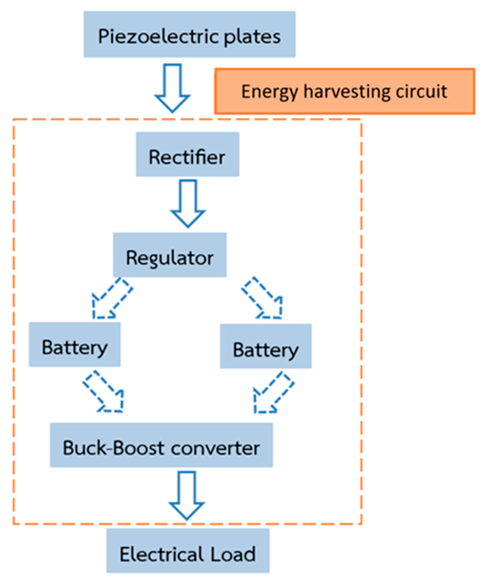
The overall energy harvesting flow chart is shown in Figure 2. A rectifier circuit converts the electrical signal from AC to DC, with a capacitor arrangement employed to reduce the ripple voltage. A voltage regulator circuit is used to reduce and maintain a constant voltage that connects to two batteries; the two batteries work as energy collectors and supply power to the load. Finally, a voltage converter increases or decreases the voltage level to meet load requirements.
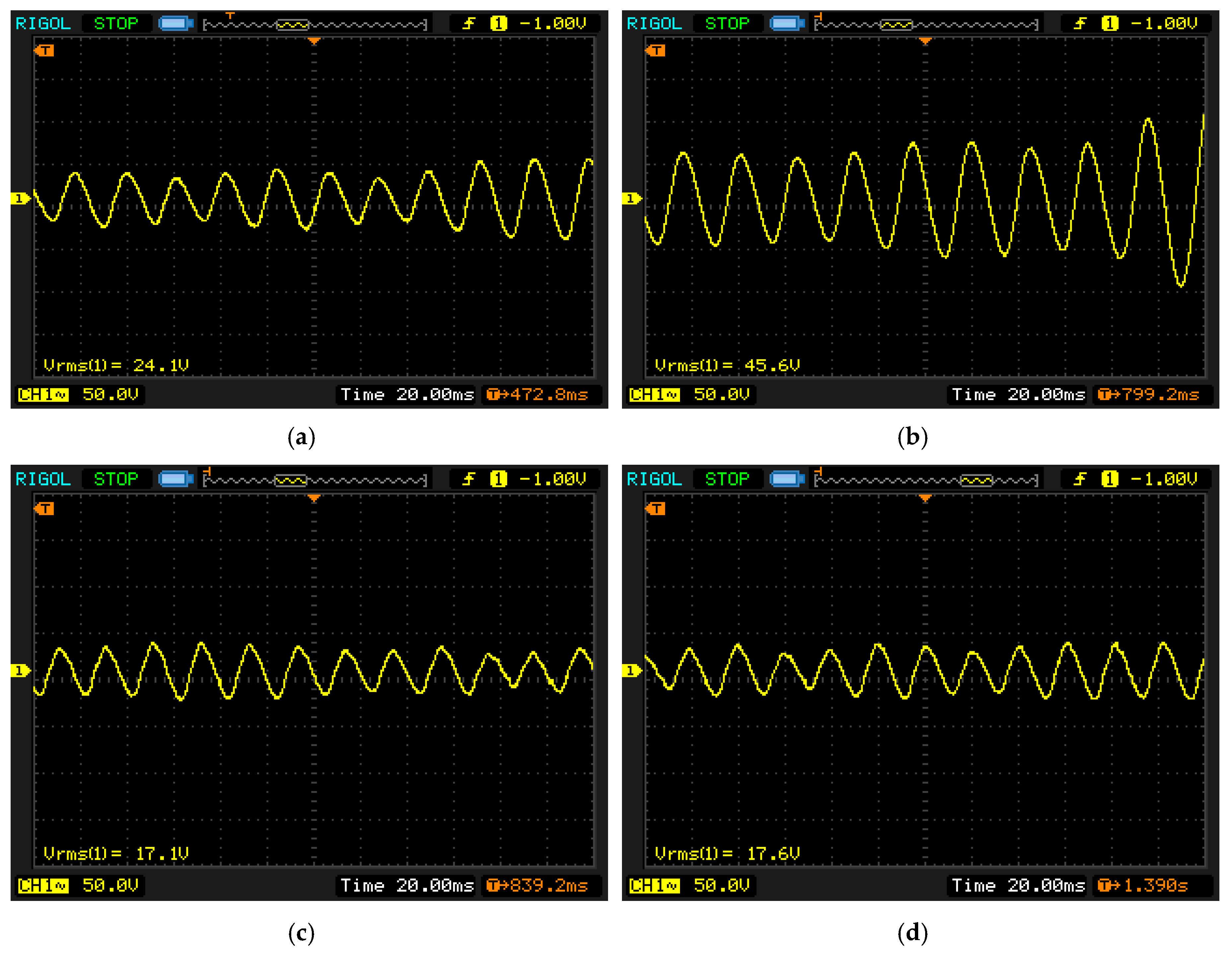
Voltage signals generated from the piezoelectric module were investigated by installing piezoelectric devices in varied configurations, from one to four modules with series and parallel circuitry configurations. Experiments were conducted at a cycling speed of 75 and 120 revolutions per minute (rpm). The open circuit voltage signals collected from the oscilloscope are seen in Figure 3, with measured electrical quantities presented in Table 1.
The pre-testing experiment excited the piezoelectric with direct force in order to study the circuit configuration that is suitable for installation in the subsequent investigations among two different speeds. The opened circuit voltage and the current when connected one kilohm resistance are measured, the output is calculated. From the experimental result, it can be seen that an average speed of 120 rpm had higher power output than 75 rpm because the piezoelectric module oscillated a greater vibration amplitude. At the same speed, the parallel configuration has a higher current and output power than the series configuration with constant voltage. Therefore, the parallel piezoelectric coupling was chosen to harvest energy from the exercise bike.
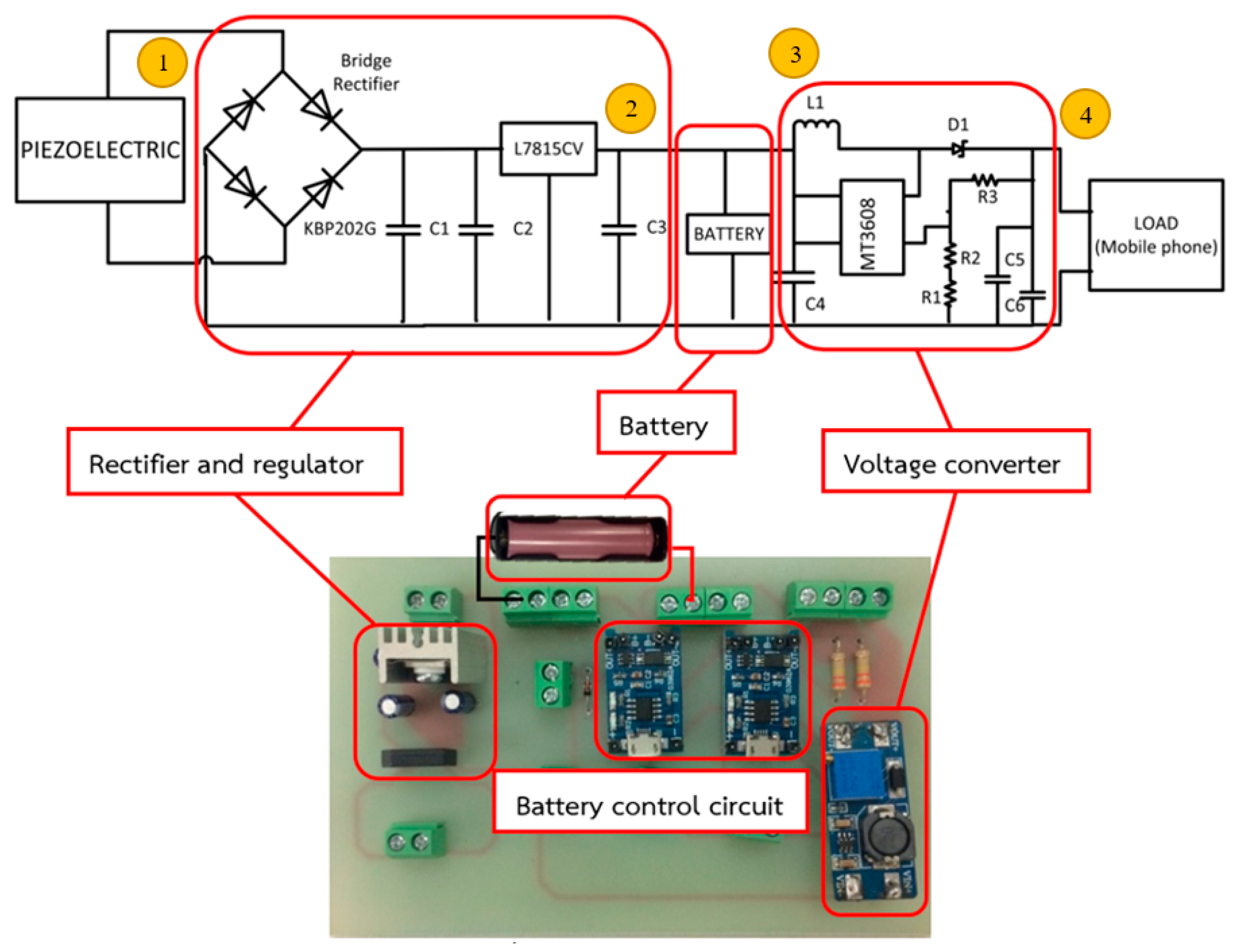
In the design of the rectifier circuit, the approximate input voltage from piezoelectric is set to 30 V; from this, the single-phase bridge rectifier KBP202G, capacitor (C1, C2, C3 = 0.1 µF) values, and positive voltage regulator L7815CV are selected to perform the energy harvesting circuit; the output voltage is equal to 15 V. The two cells are lithium-ion batteries, operating at 3.7 V, with a capacity of 2850 mAh. The energy harvesting circuit and schematic is shown in Figure 4.
Two cells, batteries A and B, are collecting energy and supplying the load alternatively, controlled by an open-source electronics platform, Arduino, set to interlocking mode. When the two cells are charging at the same time, the load consumes more current, resulting in rising heat loss and reduced battery life. The controller performs the following actions:
- If battery A has less than or equal to 50% capacity, and battery B has a more than 50% capacity, Arduino commands battery A to store energy from the piezoelectric and battery B serves the load;
- If the battery A has more than 50% capacity, and the battery B has less than or equal to 50% capacity, Arduino orders the battery A to supply the load and battery B harvest energy from the piezoelectric;
- If the batteries A and B have less than or equal to 50% capacity, Arduino commands battery A to store energy from the piezoelectric;
- If batteries A and B have more than 50% capacity, Arduino orders battery A to supply load.
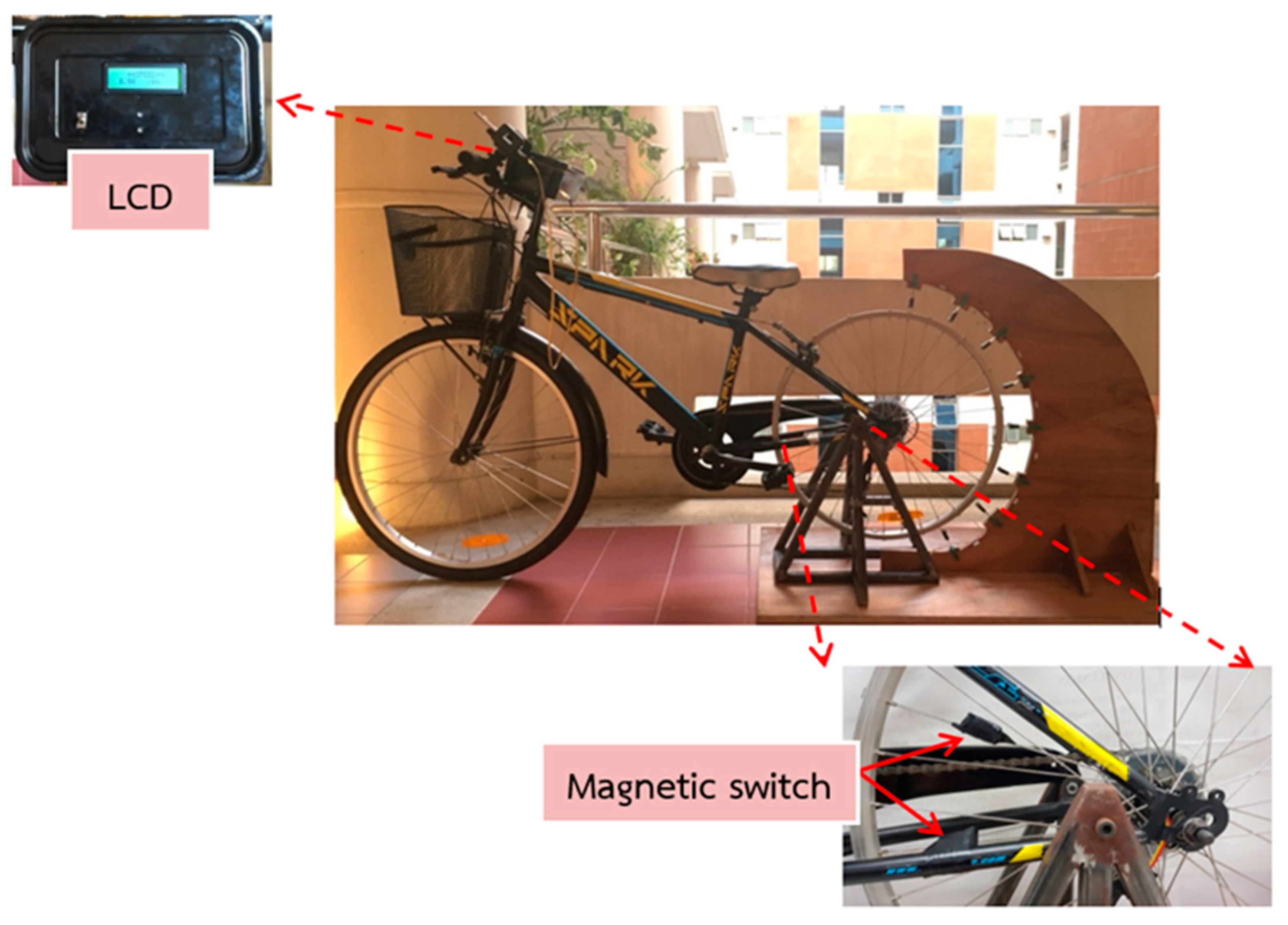
The speed measuring device uses a magnetic switch as a signal detector, with the switch consisting of two magnets positioned on the steel beam near the rear wheels, and the spokes of the rear wheels, as shown in Figure 5. When cycling, the magnet attached to the wheel spokes moves through the other magnets mounted on the steel beam. Arduino calculates and shows the speed on the LCD display mounted on the bars.
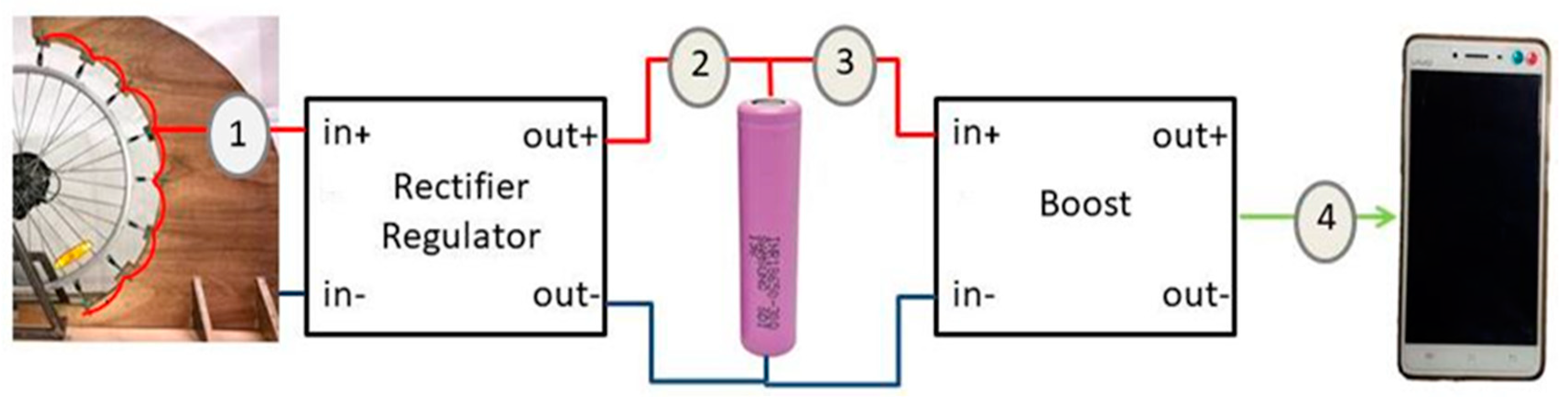
The electrical quantities were measured at three cycling speeds: 100, 120, and 140 rpm, with the measurement points shown in Figure 6. Point 1 is the AC voltage from the eight piezoelectric energy harvesters, connected in parallel. Point 2 is the DC voltage after the voltage regulation circuit. Point 3 is the DC voltage behind the battery. Point 4 is the DC voltage after the converter. The magnetic distance between the bike wheels and the piezoelectric devices was varied with different spacings, i.e., 6, 9 and 12 mm, and the results are shown in Table 2.
From the results it can be seen that at each magnetic distance, the piezoelectric apparatus generated comparable voltage output. A magnet spacing of 12 mm is chosen, as this length produced the highest magnetic force and provided clearance to protect the piezoelectric material from collision during operation.
Furthermore, at speeds of 100 and 140 rpm it was observed that the harvested energy was not being stored efficiently as battery charge. However, at a speed of 120 rpm the maximum AC voltage was observed, and the energy was stored in the battery efficiently. This is due to the optimized magnetizing force, which allows the piezoelectric modules to have the appropriate vibrating amplitude and frequency corresponding to the natural frequency of the piezoelectric material, resulting in more efficient power transfer.
3. Micro-Mobility Based on Piezoelectric Energy Harvesting
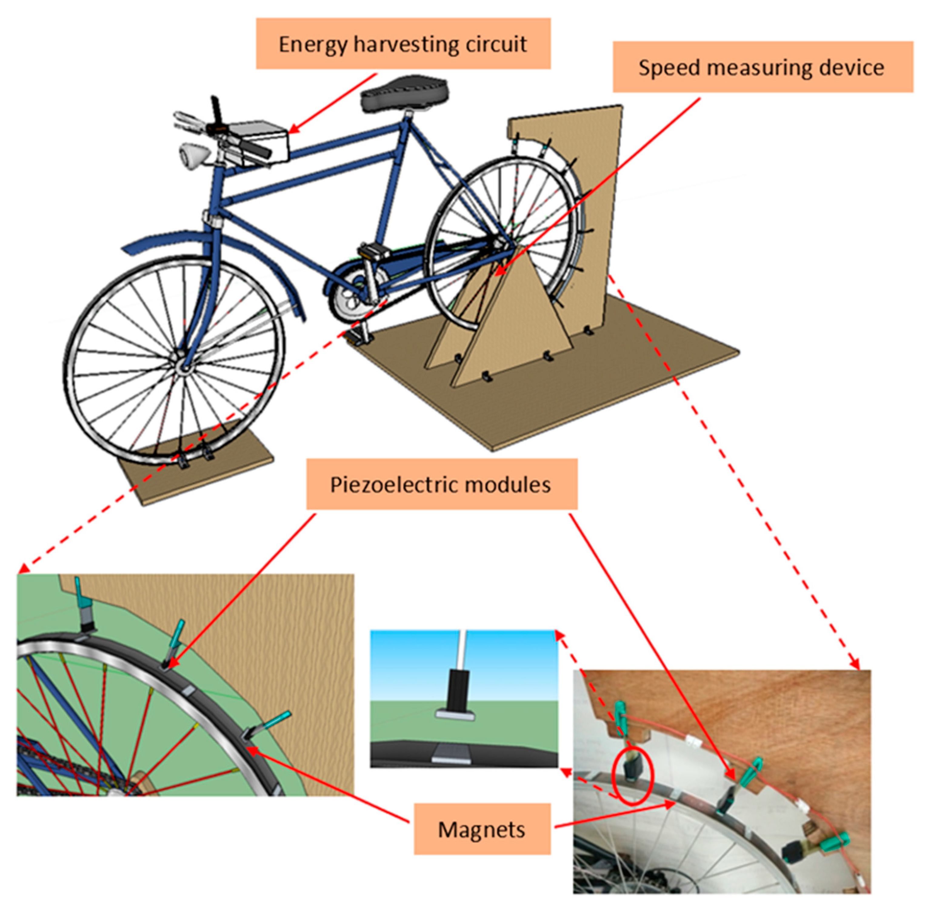
In this section, energy from the vibration force while cycling is used as the mechanical energy to generate AC in the piezoelectric material and harvested; this is achieved through an exerted electromotive force by a magnet configuration mounted to the wheels. A bicycle has been modified and developed to harvest energy; the apparatus consists of a piezoelectric circuit that is mounted on the front wheel hub and the back-wheel mudguard, a 3D-printed magnet apparatus, detection sensors and a control box in the bicycle basket. The harvesting circuit was controlled by Arduino ESP 32 Wi-Fi module and controlled via mobile application. The energy is stored in a 3200 mAh, 5 V battery in order to supply power to sensors mounted on the bicycle including a humidity and temperature sensor, ultrasonic sensor, hazardous gas detection sensor and a relay to control a 12 V light emitting diode (LED) at the front-wheel hub.
Two piezoelectric installation areas were selected on the bike: the front wheel hub, and the bike fender. The circuit control box is attached to the basket area, and contains the circuitry used to harvest energy from the piezoelectric, this includes: a charger circuit, Arduino Model ESP 32, two batteries, and a boost converter to supply LED load. The front wheel hub of the bicycle consists of eight devices, while the rear wheel mudguard was mounted with seven devices on each side. They are fastened by a bioplastic material, and a magnet attached near to the piezoelectric module imparts momentum on the piezoelectric material when the wheel spins.
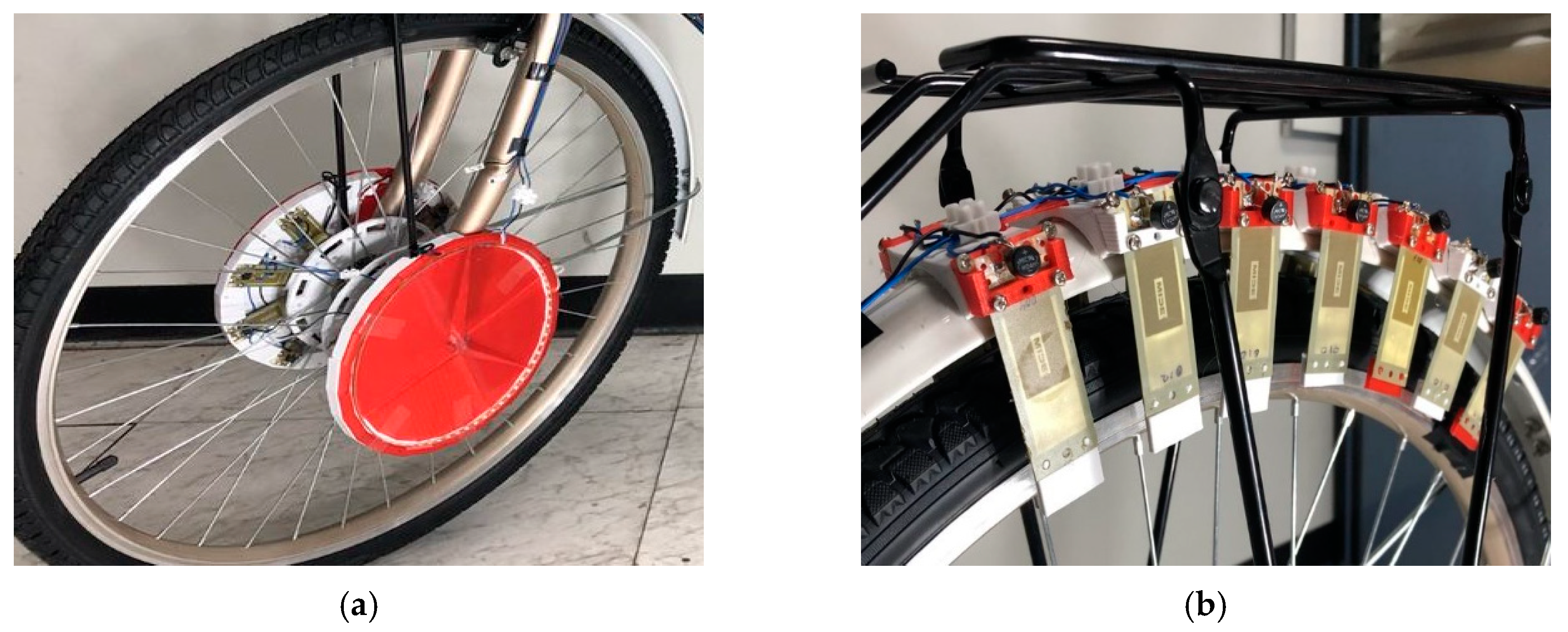
The front wheel hub of the bicycle is designed to house eight piezoelectric devices on each side. At the tip of each piezoelectric device is a magnetic bar to generate an electromotive force on the other four magnets, placed on the opposite side at the inner wheel, causing the piezoelectric material to vibrate during cycling. The energy harvesting apparatus on the front wheel uses sixteen piezoelectric devices and twenty-four magnets in total. Moreover, the bike’s rear-wheel fender area is designed to attach magnets to seven piezoelectric devices on each side, with a distance of 1.3 cm between the opposite two magnets on each side of the moving wheel. In total, eighteen magnets and fourteen piezoelectric devices are mounted on the rear wheel area, as seen in Figure 7.
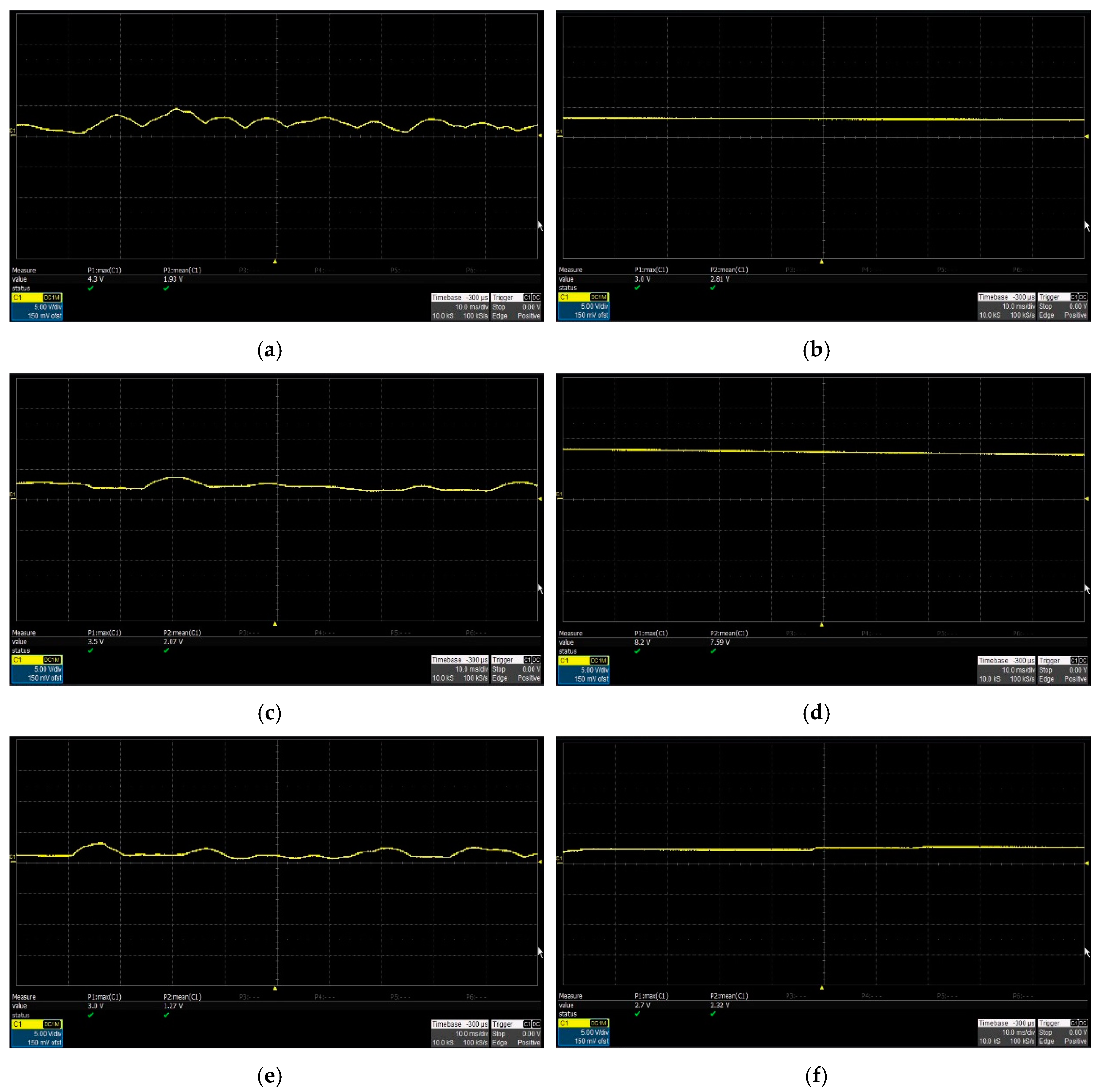
Experimental voltages were measured for a distance between the magnet and the piezo pad at the front wheel hub of 2.2 cm, and a rear wheel center area of 1.3 cm, by continuously cycling for 3 min and measuring the instantaneous voltage. The spin speed was varied between 30, 60, and 90 rpm, and the average voltage, current, and power are measured at four locations in the circuit: DC voltage after the rectifier circuit, behind the capacitor, behind the battery, and after the boost converter. The measurement point is different from the initial experiment and is shown in Figure 8, and observed electrical signals are displayed in Figure 9.
When measuring instantaneous voltage, the maximum voltage range at each speed is the result of the repulsion of the magnets, and it is seen to gradually decrease until the next magnet exerts an additional force. From the acquired signal, the voltage is continuously increasing and decreasing, with each range being unstable due to the ringing effect of the second-order system behavior, and the damping of the system in this case. When measuring at the capacitor, a steadier signal is obtained. Although the average voltage is higher, there is still an unstable range, possibly the result of unstable cycling force and magnetic contact range. The experimental results of each speed in all measurement areas are summarised in Table 3.
The small power production in the 90 rpm because the magnetic force exerted on the piezoelectric material is over too short a duration for the material to produce electrical energy at the appropriate frequency range. At 30 rpm, there is less power generation due to there being fewer vibrations in the frequency range that can produce power. Point 3 and point 4 are the areas for connecting the battery and the voltage circuit. Therefore, the resulting value is constant at all revolutions.
The influence of road surface on power generation was examined. Experiments to obtain combined voltage values of the front and back wheels when cycling on three different road surfaces at 30, 60 and 90 rpm were conducted by measuring the electrical quantities behind the capacitor under three different road surfaces using a cyclist load weight of 70 kg; the results are shown in Table 4. The three different road surfaces are: road surface type 1—smooth road surface; road surface type 2—moderately rough road surface featuring gravel; and road surface type 3—rough road surface featuring rocks and gravel.
From the results shown in the table, it can be seen that the road surface plays a role in the energy harvested during cycling. The maximum power was obtained when cycling in areas where the road surface is rough. As a result of the vibrating force of the magnets on the front wheels and rear wheel fenders, the front wheel area experiences greater vibrational force during the impact on rough surfaces, allowing more energy to be harvested. A rough road surface was seen to produce the most power compared to a moderately rough and smooth road surface, respectively.
The energy harvesting results obtained under different load weight are obtained and analysed. Values were obtained from both the front and back wheels, using different rider load weights to see the effect on electric power production. Cycling speeds of 30, 60, and 90 rpm are compared for three weight ranges 40–50 kg, 50–65 kg, and 65–80 kg, by measuring electrical quantities behind the capacitor, on a smooth road surface. The results are shown in Table 5.
From the results in Table 5, it can be that, in the case of all three rider load weights, with the same cycling speed, the power produced in each range is similar. Therefore, it can be concluded that the weight of the load has a minimal effect on the power that can be produced. The differing values may be due to spinning at uneven speeds. It was seen that the speed range that can produce the most power is 60 rpm, consistent with earlier results.
4. Conclusions
In this paper, an exercise bike has been modified by mounting a piezoelectric material apparatus on the frame, to be used as an electromechanical converter, converting the energy generated by exercise by-products into electrical energy. The installation and configuration of the piezoelectric harvesting apparatus were examined, and the location and distance of permanent magnets were investigated, to generate the maximum output energy.
From the results of the experiment adapting the energy harvesting system with piezoelectric in the first part of the experiment, a system with a moving exercise bike was developed. The efficiency of energy harvesting through the harvesting circuit was examined, with electrical measurements taken at four different positions in the circuit: the DC voltage after converter circuit, behind the capacitor, behind the battery, and after the boost converter circuit. The distance between the magnet attached to the piezoelectric plate and the magnet attached to the wheel frame was 2.2 cm for the front wheel, and 1.3 cm between the rear wheel fenders. The effect of the road surface on power generation showed that cycling on rough surfaces harvested the most energy, with more power being generated because of the additional shaking of the piezoelectric device. The influence of cyclist load weight on power generation was examined and was seen to not affect the energy harvested.
There is scope to improve the energy harvesting of this piezoelectric apparatus, through the addition of more piezoelectric modules or by increasing the magnet distance to the bicycle structure, or moving the magnets closer to each other; improving the energy harvested through the further optimization of physical parameters and density of piezoelectric modules is an area of future investigation. The results have shown promise for Internet of Things applications, in a more extensive system, that is able to support wireless device connection, self-powered micro-mobility devices are capable of generating significant data, and are an exciting prospect for Smart City design.
Author Contributions
C.J. conceptualization, formal analysis and design the experiment. P.S. performed the experiments, investigation and analyzed the data; C.J. funding acquisition, and A.N. contributed resource; C.J. wrote the paper, and A.N review and editing. All authors have read and agreed to the published version of the manuscript.
Funding
This research was funded by KING MONGKUT’S INSTITUTE OF TECHNOLOGY LADKRABANG RESEARCH FUND, THAILAND, grant number No. KREF046106.
Acknowledgments
The authors wish to gratefully acknowledge financial support for this research (No. KREF046106) from King Mongkut’s Institute of Technology Ladkrabang Research fund, Thailand.
Conflicts of Interest
The authors declare no conflict of interest.
References
- Mamat, R.; Sani, M.S.; Khoerunnisa, F.; Kadarohman, A. Target and demand for renewable energy across 10 ASEAN countries by 2040. Electr. J. 2019, 32, 1066–1070. [Google Scholar] [CrossRef]
- Hongtao, L.; Wenjia, L. The analysis of effects of clean energy power generation. Energy Procedia 2018, 152, 947–952. [Google Scholar] [CrossRef]
- Thailand Power Development Plan 2015–2036. Available online: https://www.egat.co.th/en/about-egat/strategy-policy/policy (accessed on 5 November 2019).
- Sarker, M.R.; Julai, S.; Sabri, M.F.; Said, S.M.; Islam, M.M.; Tahir, M. Review of piezoelectric energy harvesting system and application of optimization techniques to enhance the performance of the harvesting system. Sen. Actuators A Phys. 2019, 300, 1116–1134. [Google Scholar] [CrossRef]
- Chalioris, C.E.; Karayannis, C.G.; Angeli, G.M.; Papadopoulos, N.A.; Favvata, M.J.; Providakis, C.P. Applications of smart piezoelectric materials in a wireless admittance monitoring system (WiAMS) to Structures—Tests in RC elements. Case Stud. Constr. Mater. 2016, 5, 1–18. [Google Scholar] [CrossRef] [Green Version]
- Micek, P.; Grzybek, D. Wireless stress sensor based on piezoelectric energy harvesting for a rotating shaft. Sen. Actuators A Phys. 2019, 301, 1117–1144. [Google Scholar] [CrossRef]
- Bhuyan, S.; Sivanand, K.; Panda, S.K.; Kumar, R.; Hu, J. Resonance-Based Wireless Energizing of Piezoelectric Components. IEEE Magn. Lett. 2011, 2, 6000204. [Google Scholar] [CrossRef]
- Dong, H.; Wu, J.; Zhang, H.; Zhang, G. Measurement of a Piezoelectric Transducer’s Mechanical Resonant Frequency Based on Residual Vibration Signals. In Proceedings of the 2010 IEEE International Conference on Information and Automation, Harbin, China, 20–23 June 2010; pp. 1872–1876. [Google Scholar]
- Lau, B.P.L.; Marakkalage, S.H.; Zhou, Y.; Hassan, N.U.; Yuen, C.; Zhang, M.; Tan, U.X. A survey of data fusion in smart city applications. Inf. Fusion 2019, 52, 357–374. [Google Scholar] [CrossRef]
- Anjomshoaa, A.; Duarte, F.; Rennings, D.; Matarazzo, T.J.; de Souza, P.; Ratti, C. City Scanner: Building and Scheduling a Mobile Sensing Platform for Smart City Services. IEEE Internet Things J. 2018, 5, 4567–4579. [Google Scholar] [CrossRef]
- Nižetić, S.; Djilali, N.; Papadopoulos, A.; Rodrigues, J.J. Smart technologies for promotion of energy efficiency, utilization of sustainable resources and waste management. J. Clean. Prod. 2019, 231, 565–591. [Google Scholar] [CrossRef]
- Ismagilova, E.; Hughes, L.; Dwivedi, Y.K.; Raman, K.R. Smart cities: Advances in research—An information systems perspective. Int. J. Inf. Manag. 2019, 47, 88–100. [Google Scholar] [CrossRef]
- Korczak, J.; Kijewska, K. Smart Logistics in the development of Smart Cities. Transp. Res. Procedia 2019, 39, 201–211. [Google Scholar] [CrossRef]
- Haarstad, H.; Wathne, M.W. Are smart city projects catalyzing urban energy sustainability? Energy Policy 2019, 129, 918–925. [Google Scholar] [CrossRef]
- Cellina, F.; Castri, R.; Simão, J.V.; Granato, P. Co-creating app-based policy measures for mobility behavior change: A trigger for novel governance practices at the urban level. Sustain. Cities Soc. 2020, 53, 1011–1019. [Google Scholar] [CrossRef]
- Battarra, R.; Gargiulo, C.; Tremiterra, M.R.; Zucaro, F. Smart mobility in Italian metropolitan cities: A comparative analysis through indicators and actions. Sustain. Cities Soc. 2018, 41, 556–567. [Google Scholar] [CrossRef]
- Peprah, C.; Amponsah, O.; Oduro, C. A system view of smart mobility and its implications for Ghanaian cities. Sustain. Cities Soc. 2019, 44, 739–747. [Google Scholar] [CrossRef]
- Carreiro, I.L.; Monzon, A. Evaluating sustainability and innovation of mobility patterns in Spanish cities. Analysis by size and urban typology. Sustain. Cities Soc. 2018, 38, 684–696. [Google Scholar] [CrossRef]
- Din, S.; Paul, A.; Hong, W.H.; Seo, H. Constrained application for mobility management using embedded devices in the Internet of Things based urban planning in smart cities. Sustain. Cities Soc. 2019, 44, 144–151. [Google Scholar] [CrossRef]
- Sun, J.; Li, M.; Zhang, Z.; Xu, T.; He, J.; Wang, H.; Li, G. Renewable energy transmission by HVDC across the continent: System challenges and opportunities. CSEE J. Power Energy Syst. 2017, 3, 353–364. [Google Scholar] [CrossRef]
- Rahbar, K.; Chai, C.C.; Zhang, R. Energy Cooperation Optimization in Microgrids with Renewable Energy Integration. IEEE Trans. Smart Grid 2018, 9, 1482–1493. [Google Scholar] [CrossRef]
- Du, E.; Zhang, N.; Hodge, B.M.; Wang, Q.; Kang, C.; Kroposki, B.; Xia, Q. The Role of Concentrating Solar Power Toward High Renewable Energy Penetrated Power Systems. IEEE Trans. Power Syst. 2018, 33, 6630–6641. [Google Scholar] [CrossRef]
- Zhou, B.; Xu, D.; Li, C.; Chung, C.Y.; Cao, Y.; Chan, K.W.; Wu, Q. Optimal Scheduling of Biogas–Solar–Wind Renewable Portfolio for Multicarrier Energy Supplies. IEEE Trans. Power Syst. 2018, 33, 6229–6239. [Google Scholar] [CrossRef] [Green Version]
- Qazi, A.; Hussain, F.; Rahim, N.A.; Hardaker, G.; Alghazzawi, D.; Shaban, K.; Haruna, K. Towards Sustainable Energy: A Systematic Review of Renewable Energy Sources, Technologies, and Public Opinions. IEEE Access 2019, 7, 63837–63851. [Google Scholar] [CrossRef]
- Huang, W.; Zhang, N.; Yang, J.; Wang, Y.; Kang, C. Optimal Configuration Planning of Multi-Energy Systems Considering Distributed Renewable Energy. IEEE Trans. Smart Grid 2019, 10, 1452–1464. [Google Scholar] [CrossRef]
- Cao, Y.; Figueroa, J.; Pastrana, J.J.; Li, W.; Chen, Z.; Wang, Z.L.; Sepúlveda, N. Flexible ferroelectret polymer for self-powering devices and energy storage systems. ACS Appl. Mater. Interfaces 2019, 11, 17400–17409. [Google Scholar] [CrossRef]
- Li, W.; Torres, D.; Wang, T.; Wang, C.; Sepúlveda, N. Flexible and biocompatible polypropylene ferroelectret nanogenerator (FENG): On the path toward wearable devices powered by human motion. Nano Energy 2016, 30, 649–657. [Google Scholar] [CrossRef] [Green Version]
- Wan, H.; Cao, Y.; Lo, L.W.; Xu, Z.; Sepúlveda, N.; Wang, C. Screen-printed soft triboelectric nanogenerator with porous PDMS and stretchable PEDOT: PSS electrode. J. Semicond. 2019, 40, 112601. [Google Scholar] [CrossRef]
- Wang, Y.; Zhang, Q.; Zhao, L.; Kim, E.S. Non-Resonant, Electromagnetic Broad-Band Vibration-Energy Harvester Based on Self-Assembled Ferrofluid Liquid Bearing. IEEE/ASME J. Microelectromech. Syst. 2017, 26, 809–819. [Google Scholar] [CrossRef]
- Zhang, Q.; Wang, Y.; Zhao, L.; Kim, E.S. Integration of microfabricated low resistance and thousand-turn coils for vibration energy harvesting. J. Micromech. Microeng. 2016, 26. [Google Scholar] [CrossRef]
- Ali, F.; Raza, W.; Li, X.; Gul, H.; Kim, K.H. Piezoelectric energy harvesters for biomedical applications. Nano Energy 2019, 57, 879–902. [Google Scholar] [CrossRef]
- Kulkarni, H.; Zohaib, K.; Khusru, A.; Aiyappa, K.S. Application of piezoelectric technology in automotive systems. Mater. Today Proc. 2018, 5, 21299–21304. [Google Scholar] [CrossRef]
- Chen, J.; Qiu, Q.; Han, Y.; Lau, D. Piezoelectric materials for sustainable building structures: Fundamentals and applications. Renew. Sustain. Energy Rev. 2019, 101, 14–25. [Google Scholar] [CrossRef]
- Tang, B.; Akbari, H.; Pouya, M.; Pashaki, P.V. Application of piezoelectric patches for chatter suppression in machining processes. Measurement 2019, 138, 225–231. [Google Scholar] [CrossRef]
- Xu, X.; Cao, D.; Yang, H.; He, M. Application of piezoelectric transducer in energy harvesting in pavement. Int. J. Pavement Res. Technol. 2018, 11, 388–395. [Google Scholar] [CrossRef]
- Yang, Z.; Zhou, S.; Zu, J.; Inman, D. High-Performance Piezoelectric Energy Harvesters and Their Applications. Joule 2018, 2, 642–697. [Google Scholar] [CrossRef] [Green Version]
- Elhalwagy, A.M.; Ghoneem, M.Y.M.; Elhadidi, M. Feasibility Study for Using Piezoelectric Energy Harvesting Floor in Buildings’ Interior Spaces. Energy Procedia 2017, 115, 114–126. [Google Scholar] [CrossRef]
- Garimella, R.C.; Sastry, V.R.; Mohiuddin, M.S. Piezo-Gen—An Approach to Generate Electricity from Vibrations. Procedia Earth Planet. Sci. 2015, 11, 445–456. [Google Scholar] [CrossRef] [Green Version]
- Laumann, F.; Sørensen, M.M.; Lindemann, R.F.J.; Hansen, T.M.; Tambo, T. Energy harvesting through piezoelectricity—Technology foresight. Energy Procedia 2017, 142, 3062–3068. [Google Scholar] [CrossRef]
- Yang, Z.; Erturk, A.; Zu, J. On the efficiency of piezoelectric energy harvesters. Extrem. Mecha. Lett. 2017, 15, 26–37. [Google Scholar] [CrossRef]
- Wei, C.; Jing, X. A comprehensive review on vibration energy harvesting: Modelling and realization. Renew. Sustain. Energy Rev. 2017, 74, 1–18. [Google Scholar] [CrossRef]
- Zhang, H.; Corr, L.R.; Ma, T. Issues in vibration energy harvesting. J. Sound Vib. 2018, 421, 79–90. [Google Scholar] [CrossRef]
- Tran, N.; Ghayesh, M.H.; Arjomandi, M. Ambient vibration energy harvesters: A review on nonlinear techniques for performance enhancement. Int. J. Eng. Sci. 2018, 127, 162–185. [Google Scholar] [CrossRef]
- Yildirim, T.; Ghayesh, M.H.; Li, W.; Alici, G. A review on performance enhancement techniques for ambient vibration energy harvesters. Renew. Sustain. Energy Rev. 2017, 71, 435–449. [Google Scholar] [CrossRef] [Green Version]
- Cao, Y.; Figueroa, J.; Li, W.; Chen, Z.; Wang, Z.L.; Sepúlveda, N. Understanding the dynamic response in ferroelectret nanogenerators to enable self-powered tactile systems and human-controlled micro-robots. Nano Energy 2019, 63. [Google Scholar] [CrossRef]
- Cao, Y.; Li, W.; Sepúlveda, N. Performance of Self-Powered, Water-Resistant Bending Sensor Using Transverse Piezoelectric Effect of Polypropylene Ferroelectret Polymer. IEEE Sen. J. 2019, 19, 10327–10335. [Google Scholar] [CrossRef]
Figure 1.
Schematic of exercise bike implemented with energy harvesting system using a piezoelectric material.
Figure 1.
Schematic of exercise bike implemented with energy harvesting system using a piezoelectric material.

Figure 2.
The Piezoelectric energy harvesting circuit flow chart.

Figure 3.
The voltage signal from the various configurations of piezoelectric modules at average speeds 75 rpm: (a) Two piezoelectric modules connected in series; (b) Four piezoelectric modules connected in series; (c) Two piezoelectric modules connected in parallel; (d) Four piezoelectric modules connected in parallel

Figure 4.
Piezoelectric energy harvesting circuit and measurement position.

Figure 5.
The speed measuring devices mounted on energy harvesting exercise bicycle.

Figure 6.
Measurement points of electrical quantities within the energy harvesting circuit.

Figure 7.
The actual installation of piezoelectric modules on a bicycle: (a) Piezoelectric modules installation distance at front wheel; (b) Piezoelectric modules installation distance at rear wheel fenders.
Figure 7.
The actual installation of piezoelectric modules on a bicycle: (a) Piezoelectric modules installation distance at front wheel; (b) Piezoelectric modules installation distance at rear wheel fenders.

Figure 8.
The measurement points in bicycle experiment.

Figure 9.
The DC voltage signal at position 1 and position 2 at various speeds: (a) Position 1 at the speed of 30 rpm; (b) Position 2 at the speed of 30 rpm; (c) Position 1 at the speed of 60 rpm; (d) Position 2 at the speed of 60 rpm; (e) Position 1 at the speed of 90 rpm; (f) Position 2 at the speed of 90 rpm.

Table 1.
Summary of experimental results of electrical quantities from the piezoelectric devices.
| Configurations | Average Speed | ||||||
|---|---|---|---|---|---|---|---|
| 75 rpm | 120 rpm | ||||||
| Open Circuit Voltage (V) | Current (mA) | Power (µW) | Open Circuit Voltage (V) | Current (mA) | Power (µW) | ||
| Base case | One module | 14.4 | 0.09 | 8.10 | 22.5 | 0.10 | 10.10 |
| Series | Two modules | 24.1 | 0.10 | 10.10 | 30.3 | 0.11 | 12.10 |
| Three modules | 38.9 | 0.12 | 14.40 | 44.1 | 0.14 | 19.60 | |
| Four modules | 45.6 | 0.13 | 16.90 | 48.7 | 0.15 | 22.50 | |
| Parallel | Two modules | 17.1 | 0.19 | 36.10 | 23.6 | 0.23 | 52.90 |
| Three modules | 17.3 | 0.28 | 78.40 | 24.2 | 0.33 | 108.90 | |
| Four modules | 17.6 | 0.37 | 136.90 | 26.4 | 0.42 | 176.40 | |
Table 2.
Experimentally measured electrical quantities at various cycling speeds at magnetic distances of 6, 9 and 12 mm.
Table 2.
Experimentally measured electrical quantities at various cycling speeds at magnetic distances of 6, 9 and 12 mm.
| Measurement Points | Magnetic Distance 6 mm | Magnetic Distance 9 mm | Magnetic Distance 12 mm | |||||||
|---|---|---|---|---|---|---|---|---|---|---|
| 100 rpm | 120 rpm | 140 rpm | 100 rpm | 120 rpm | 140 rpm | 100 rpm | 120 rpm | 140 rpm | ||
| Point 1 | Voltage (V) | 5.67 | 6.03 | 5.11 | 5.20 | 6.09 | 5.15 | 5.25 | 5.69 | 5.14 |
| Current (mA) | 18 | 20 | 14 | 14 | 20 | 15 | 14 | 18 | 15 | |
| Power (mW) | 102.1 | 120.6 | 71.54 | 72.8 | 121.8 | 77.25 | 73.5 | 102.4 | 77.1 | |
| Point 2 | Voltage (V) | 3.76 | 4.16 | 3.92 | 3.52 | 4.20 | 3.20 | 3.36 | 4.16 | 3.20 |
| Current (mA) | 8 | 9 | 8 | 8 | 9 | 8 | 8 | 9 | 8 | |
| Power (mW) | 30.08 | 37.44 | 31.36 | 28.16 | 37.8 | 25.6 | 26.88 | 37.44 | 25.6 | |
| Point 3 | Voltage (V) | 3.92 | 3.92 | 3.92 | 3.92 | 3.92 | 3.92 | 3.92 | 3.92 | 3.92 |
| Current (mA) | 88 | 88 | 88 | 88 | 88 | 88 | 88 | 88 | 88 | |
| Power (mW) | 345 | 345 | 345 | 345 | 345 | 345 | 345 | 345 | 345 | |
| Point 4 | Voltage (V) | 5.68 | 5.68 | 5.68 | 5.68 | 5.68 | 5.68 | 5.68 | 5.68 | 5.68 |
| Current (mA) | 88 | 88 | 88 | 88 | 88 | 88 | 88 | 88 | 88 | |
| Power (mW) | 500 | 500 | 500 | 500 | 500 | 500 | 500 | 500 | 500 | |
Table 3.
Electrical quantities obtained from cycling at various speeds
| Measurement Points | Cycling Speed (rpm) | |||
|---|---|---|---|---|
| 30 | 60 | 90 | ||
| Point 1 | Voltage (V) | 1.93 | 2.81 | 2.62 |
| Current (mA) | 0.37 | 1.72 | 1.79 | |
| Power (mW) | 0.71 | 4.83 | 4.69 | |
| Point 2 | Voltage (V) | 2.07 | 7.59 | 7.04 |
| Current (mA) | 0.33 | 0.63 | 0.63 | |
| Power (mW) | 0.68 | 4.78 | 4.56 | |
| Point 3 | Voltage (V) | 3.80 | 3.80 | 3.80 |
| Current (mA) | 1.46 | 1.46 | 1.46 | |
| Power (mW) | 5.55 | 5.55 | 5.55 | |
| Point 4 | Voltage (V) | 10.00 | 10.00 | 10.00 |
| Current (mA) | 0.50 | 0.50 | 0.50 | |
| Power (mW) | 5.00 | 5.00 | 5.00 | |
Table 4.
The electrical quantities obtained from cycling at various speeds on various road surfaces.
Table 4.
The electrical quantities obtained from cycling at various speeds on various road surfaces.
| Measurement Conditions | Cycling Speed (rpm) | |||
|---|---|---|---|---|
| 30 | 60 | 90 | ||
| Smooth road surface | Voltage (V) | 8.54 | 11.44 | 9.73 |
| Current (mA) | 0.88 | 1.15 | 0.95 | |
| Power (mW) | 7.53 | 13.11 | 9.20 | |
| Moderately rough road surface | Voltage (V) | 10.69 | 11.49 | 11.49 |
| Current (mA) | 0.86 | 1.18 | 0.98 | |
| Power (mW) | 9.21 | 13.59 | 11.21 | |
| Rough road surface | Voltage (V) | 10.46 | 12.92 | 10.74 |
| Current (mA) | 0.92 | 1.17 | 1.25 | |
| Power (mW) | 9.67 | 15.08 | 13.38 | |
Table 5.
Electrical quantities obtained from cycling at various speeds on various weight ranges.
| Measurement Conditions | Cycling Speed (rpm) | |||
|---|---|---|---|---|
| 30 | 60 | 90 | ||
| Weight 40–50 kg. | Voltage (V) | 8.54 | 11.49 | 9.73 |
| Current (mA) | 0.88 | 1.18 | 0.95 | |
| Power (mW) | 7.53 | 13.59 | 9.20 | |
| Weight 50–65 kg. | Voltage (V) | 8.21 | 12.09 | 9.62 |
| Current (mA) | 0.92 | 1.01 | 0.96 | |
| Power (mW) | 7.57 | 12.19 | 9.24 | |
| Weight 65–80 kg. | Voltage (V) | 8.79 | 11.79 | 9.39 |
| Current (mA) | 0.79 | 1.06 | 0.73 | |
| Power (mW) | 6.91 | 12.51 | 6.92 | |
© 2020 by the authors. Licensee MDPI, Basel, Switzerland. This article is an open access article distributed under the terms and conditions of the Creative Commons Attribution (CC BY) license (http://creativecommons.org/licenses/by/4.0/).
Share and Cite
MDPI and ACS Style
Jettanasen, C.; Songsukthawan, P.; Ngaopitakkul, A. Development of Micro-Mobility Based on Piezoelectric Energy Harvesting for Smart City Applications. Sustainability 2020, 12, 2933. https://0-doi-org.brum.beds.ac.uk/10.3390/su12072933
AMA Style
Jettanasen C, Songsukthawan P, Ngaopitakkul A. Development of Micro-Mobility Based on Piezoelectric Energy Harvesting for Smart City Applications. Sustainability. 2020; 12(7):2933. https://0-doi-org.brum.beds.ac.uk/10.3390/su12072933
Chicago/Turabian StyleJettanasen, Chaiyan, Panapong Songsukthawan, and Atthapol Ngaopitakkul. 2020. "Development of Micro-Mobility Based on Piezoelectric Energy Harvesting for Smart City Applications" Sustainability 12, no. 7: 2933. https://0-doi-org.brum.beds.ac.uk/10.3390/su12072933
Note that from the first issue of 2016, this journal uses article numbers instead of page numbers. See further details here.