
Experimental Study of a Small-Size Vacuum Insulated Water Tank for Building Applications

 ,
,  , , and
Abstract
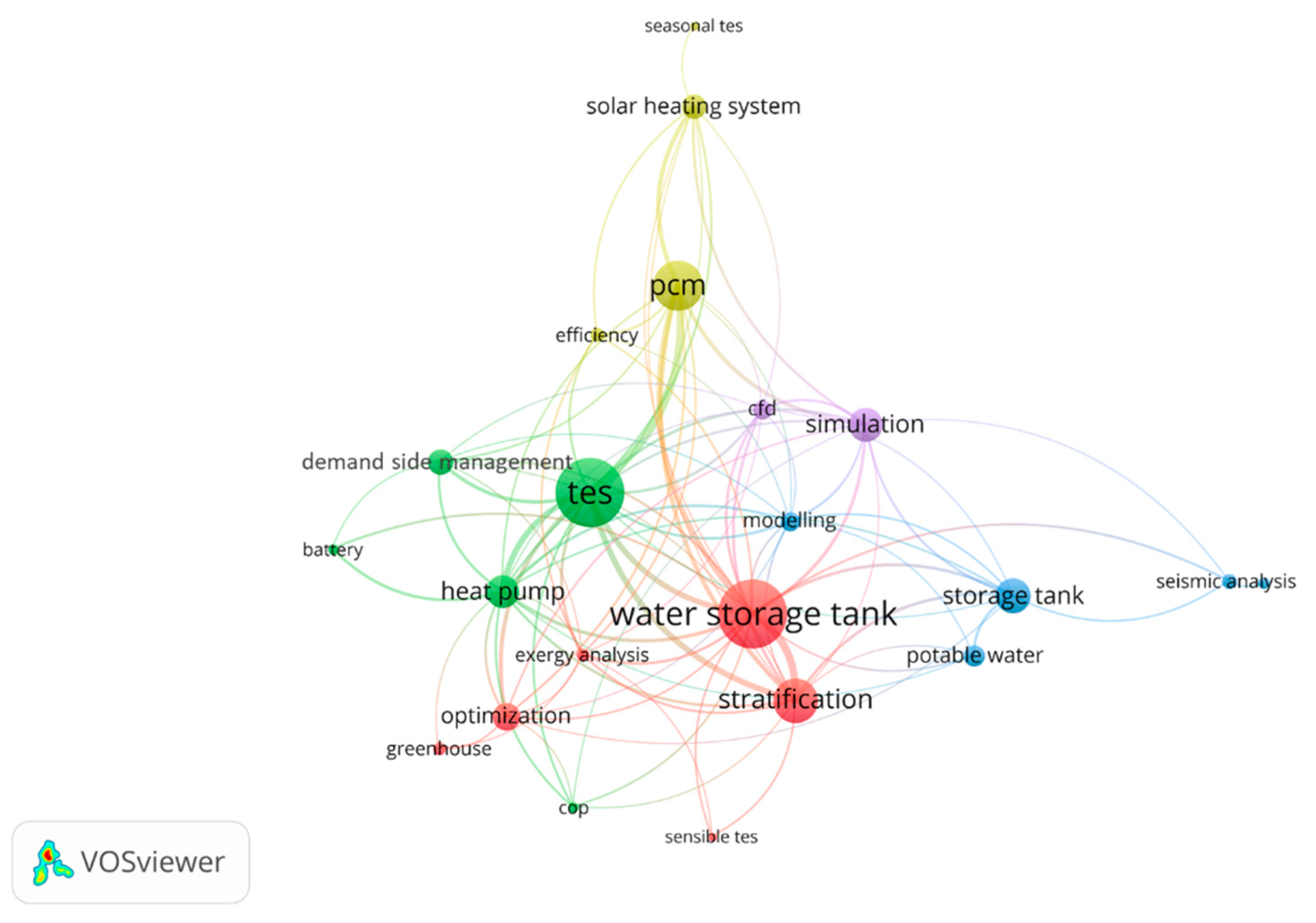
:1. Introduction
2. Materials and Methods
2.1. Experimental Methodology
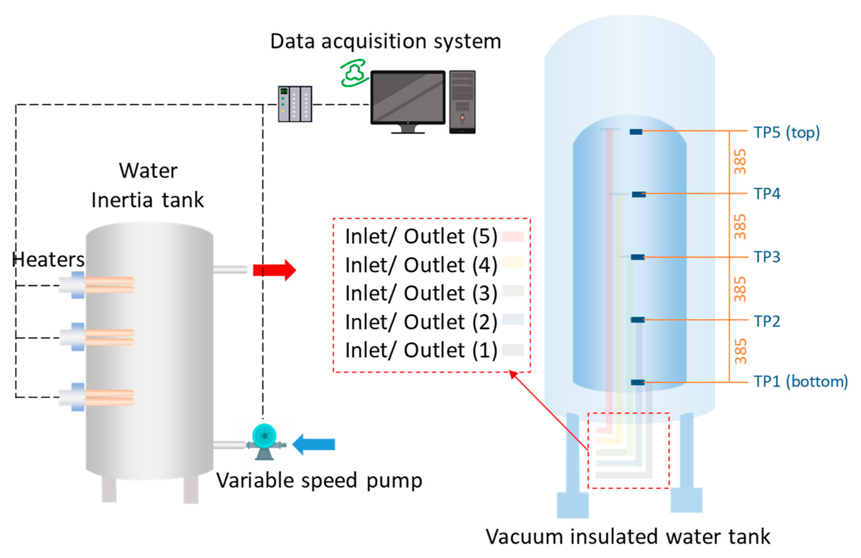
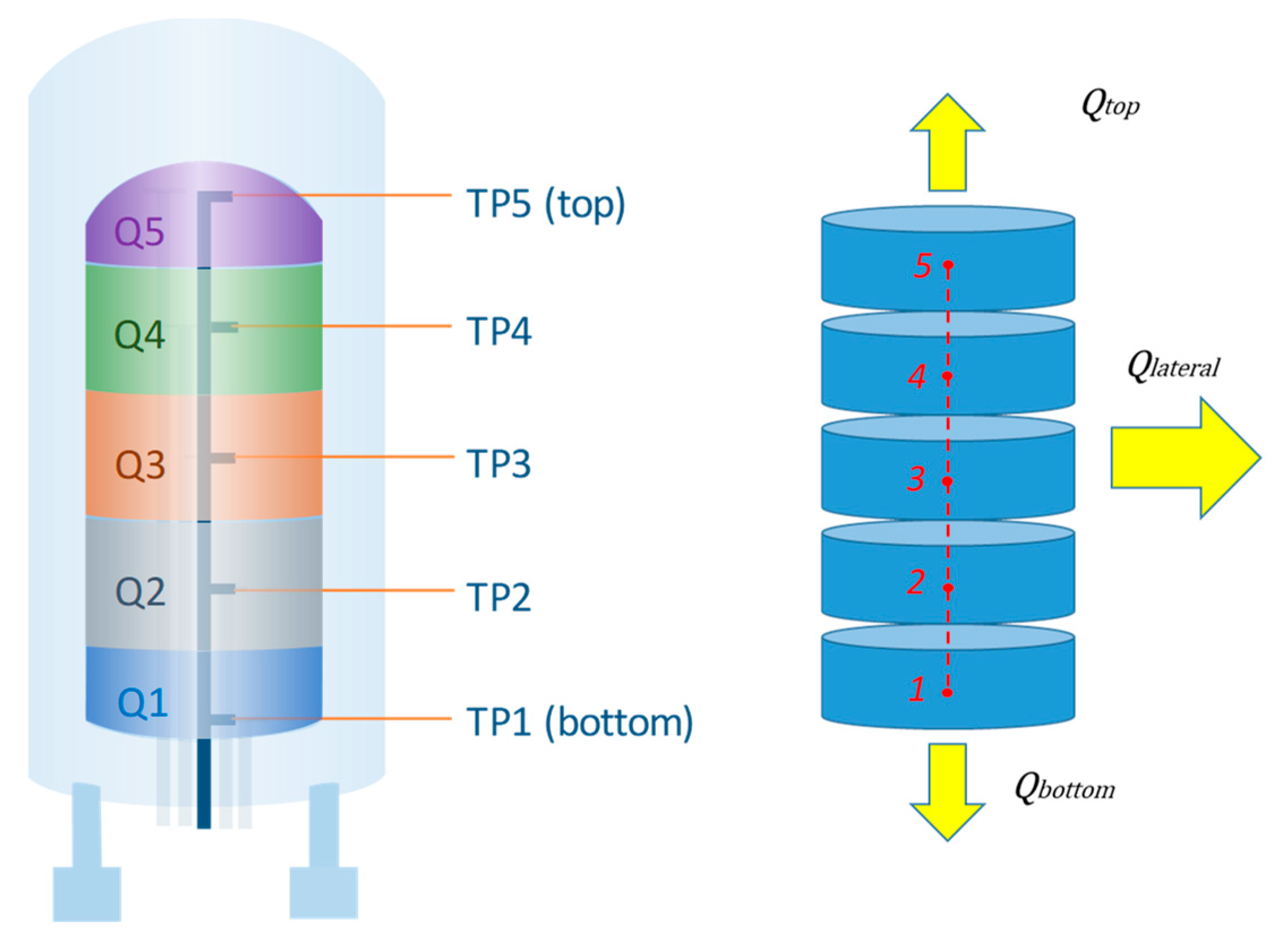
2.1.1. Experimental Set-Up
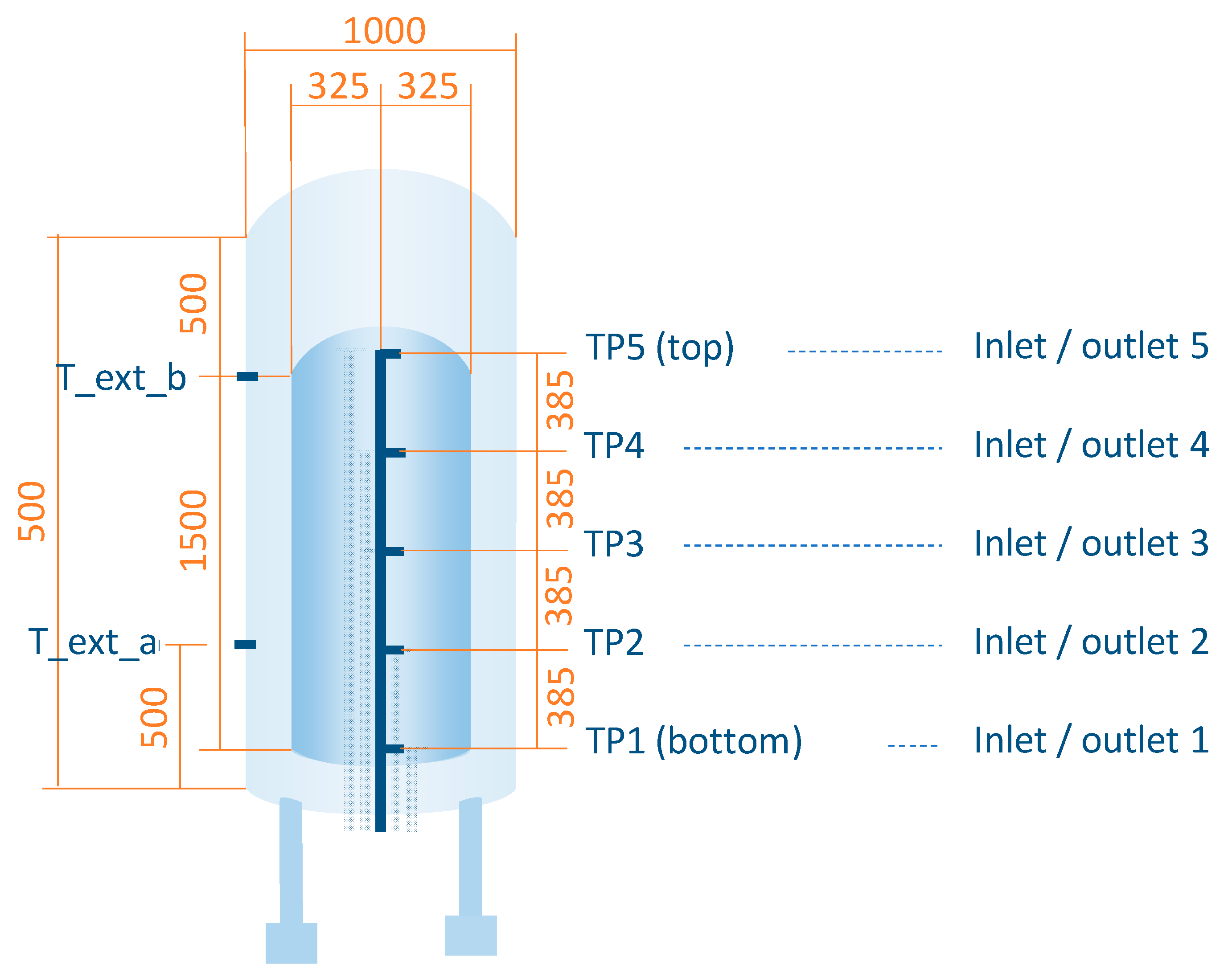
2.1.2. Characteristics of the Water Tank
2.1.3. Heat Losses Test
- Test A: water tank is preheated at a uniform temperature of 65 °C;
- Test B: water tank is preheated at 45 °C at the bottom and middle layers, and at 65 °C at the top.
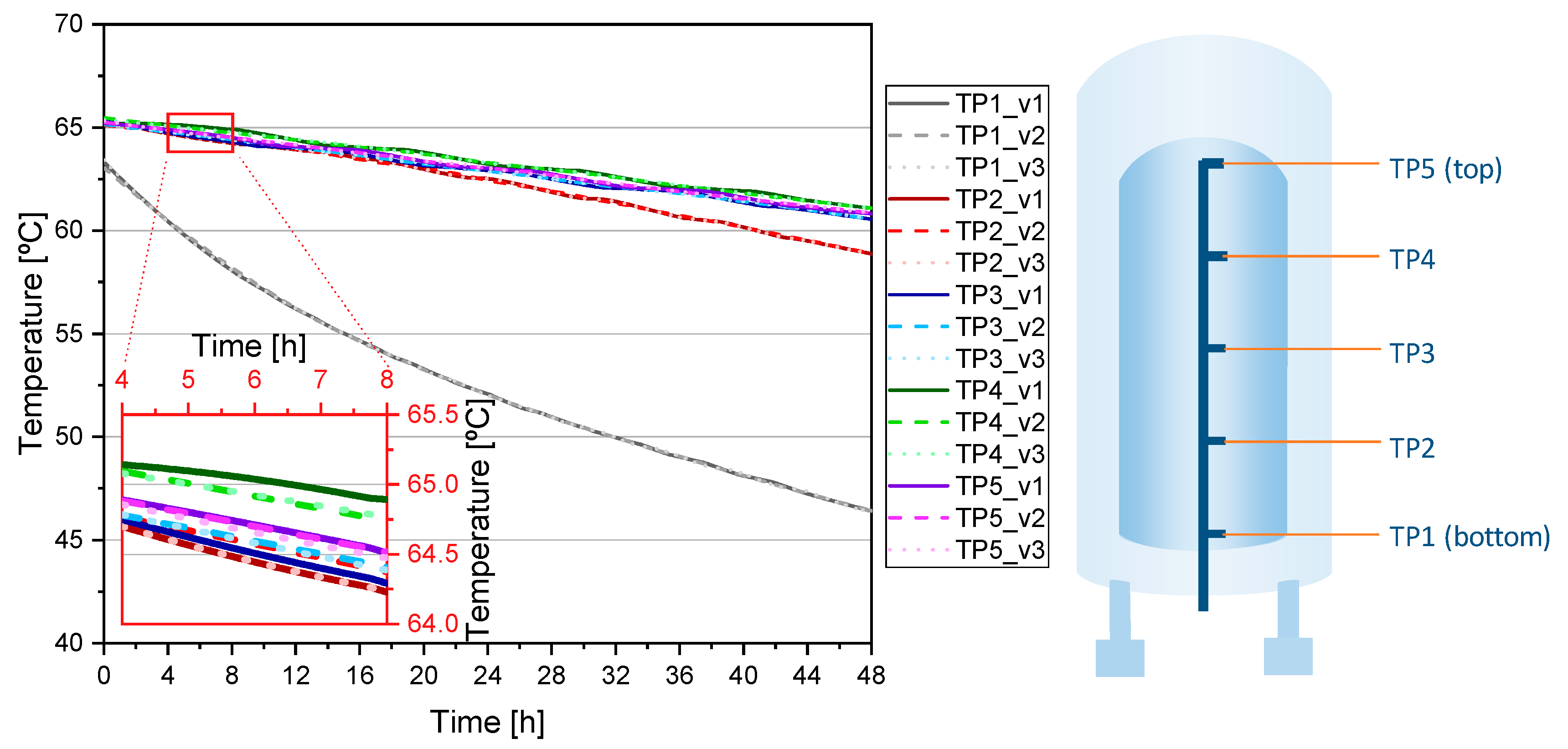
2.1.4. Repeatability of Results
2.2. Theoretical Methodology
3. Results
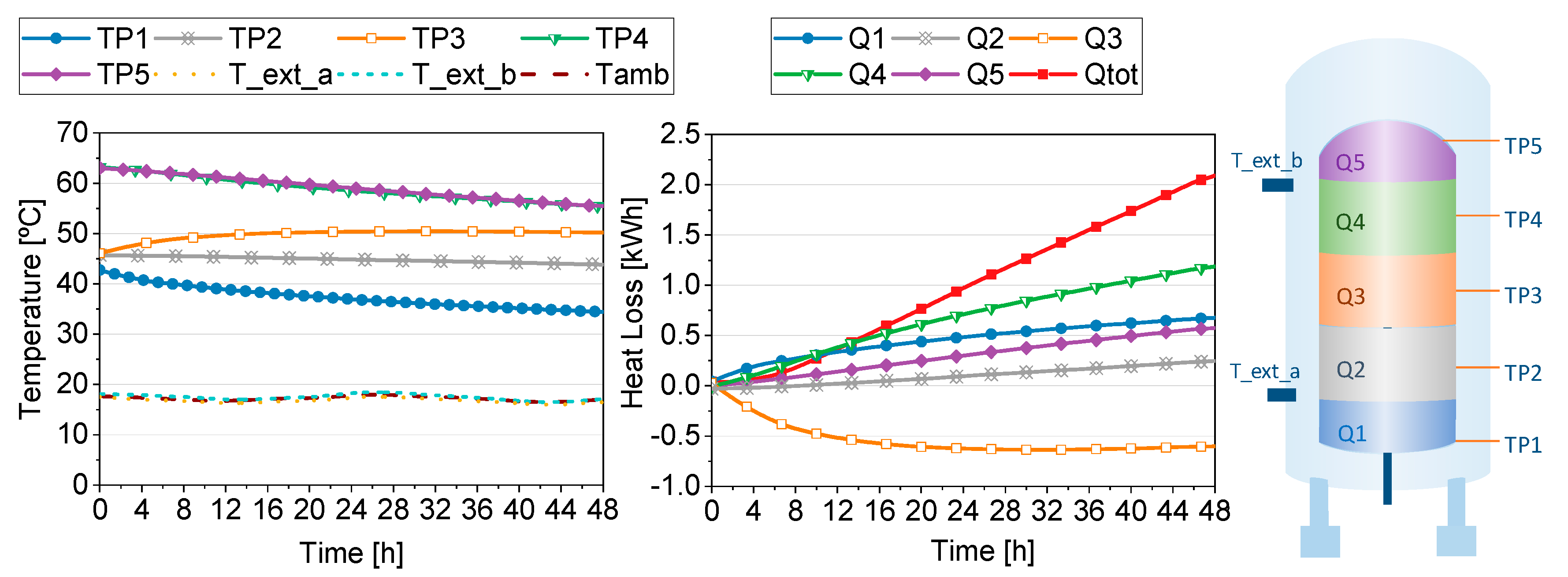
3.1. Heat Losses Test Results
3.1.1. Test A
3.1.2. Test B
3.2. U-Value Calculation
4. Discussion and Conclusions
Author Contributions
Funding
Institutional Review Board Statement
Informed Consent Statement
Data Availability Statement
Acknowledgments
Conflicts of Interest
References
- Navarro, L.; de Gracia, A.; Colclough, S.; Browne, M.; McCormack, S.J.; Griffiths, P.; Cabeza, L.F. Thermal energy storage in building integrated thermal systems: A review. Part 1. active storage systems. Renew. Energy 2016, 88, 526–547. [Google Scholar] [CrossRef] [Green Version]
- Arce, P.; Medrano, M.; Gil, A.; Oró, E.; Cabeza, L.F. Overview of thermal energy storage (TES) potential energy savings and climate change mitigation in Spain and Europe. Appl. Energy 2011, 88, 2764–2774. [Google Scholar] [CrossRef]
- Borri, E.; Tafone, A.; Zsembinszki, G.; Comodi, G.; Romagnoli, A.; Cabeza, L.F. Recent Trends on Liquid Air Energy Storage: A Bibliometric Analysis. Appl. Sci. 2020, 10, 2773. [Google Scholar] [CrossRef]
- Borri, E.; Zsembinszki, G.; Cabeza, L.F. Recent developments of thermal energy storage applications in the built environment: A bibliometric analysis and systematic review. Appl. Therm. Eng. 2021, 189, 116666. [Google Scholar] [CrossRef]
- Cabeza, L.F.; Frazzica, A.; Chàfer, M.; Vérez, D.; Palomba, V. Research trends and perspectives of thermal management of electric batteries: Bibliometric analysis. J. Energy Storage 2020, 32, 101976. [Google Scholar] [CrossRef]
- van Eck, N.J.; Waltman, L. Software survey: VOSviewer, a computer program for bibliometric mapping. Scientometrics 2010, 84, 523–538. [Google Scholar] [CrossRef] [PubMed] [Green Version]
- Kurşun, B.; Ökten, K. Effect of rectangular hot water tank position and aspect ratio on thermal stratification enhancement. Renew. Energy 2018, 116, 639–646. [Google Scholar] [CrossRef]
- Fan, J.; Furbo, S. Thermal stratification in a hot water tank established by heat loss from the tank. Sol. Energy 2012, 86, 3460–3469. [Google Scholar] [CrossRef]
- Han, Y.M.; Wang, R.Z.; Dai, Y.J. Thermal stratification within the water tank. Renew. Sustain. Energy Rev. 2009, 13, 1014–1026. [Google Scholar] [CrossRef]
- Dragsted, J.; Furbo, S.; Dannemand, M.; Bava, F. Thermal stratification built up in hot water tank with different inlet stratifiers. Sol. Energy 2017, 147, 414–425. [Google Scholar] [CrossRef] [Green Version]
- Chandra, Y.P.; Matuska, T. Stratification analysis of domestic hot water storage tanks: A comprehensive review. Energy Build. 2019, 187, 110–131. [Google Scholar] [CrossRef]
- Castell, A.; Medrano, M.; Solé, C.; Cabeza, L.F. Dimensionless numbers used to characterize strati fi cation in water tanks for discharging at low fl ow rates. Renew. Energy 2010, 35, 2192–2199. [Google Scholar] [CrossRef]
- Mazman, M.; Cabeza, L.F.; Mehling, H.; Nogues, M.; Evliya, H.; Paksoy, H.Ö. Utilization of phase change materials in solar domestic hot water systems. Renew. Energy 2009, 34, 1639–1643. [Google Scholar] [CrossRef]
- Mehling, H.; Cabeza, L.F.; Hippeli, S.; Hiebler, S. PCM-module to improve hot water heat stores with stratification. Renew. Energy 2003, 28, 699–711. [Google Scholar] [CrossRef]
- Klein, K.; Herkel, S.; Henning, H.-M.; Felsmann, C. Load shifting using the heating and cooling system of an office building: Quantitative potential evaluation for different flexibility and storage options. Appl. Energy 2017, 203, 917–937. [Google Scholar] [CrossRef]
- Yan, C.; Xue, X.; Wang, S.; Cui, B. A novel air-conditioning system for proactive power demand response to smart grid. Energy Convers. Manag. 2015, 102, 239–246. [Google Scholar] [CrossRef]
- Comodi, G.; Giantomassi, A.; Severini, M.; Squartini, S.; Ferracuti, F.; Fonti, A.; Nardi Cesarini, D.; Morodo, M.; Polonara, F. Multi-apartment residential microgrid with electrical and thermal storage devices: Experimental analysis and simulation of energy management strategies. Appl. Energy 2015, 137, 854–866. [Google Scholar] [CrossRef]
- Sirch Tankbau-Tankservice-Speicherbau GmbH. Available online: https://www.sirch.com/ (accessed on 20 April 2021).
- Villasmil, W.; Fischer, L.J.; Worlitschek, J. A review and evaluation of thermal insulation materials and methods for thermal energy storage systems. Renew. Sustain. Energy Rev. 2019, 103, 71–84. [Google Scholar] [CrossRef]
- Fuchs, B.; Hofbeck, K.; Faulstich, M. Vacuum insulation panels—A promising solution for high insulated tanks. Energy Procedia 2012, 30, 424–427. [Google Scholar] [CrossRef] [Green Version]
- Kang, M.; Kim, J.; You, H.; Chang, D. Experimental investigation of thermal stratification in cryogenic tanks. Exp. Therm. Fluid Sci. 2018, 96, 371–382. [Google Scholar] [CrossRef]
- Edward, L.; Filip, L. Influence of vacuum level on insulation thermal performance for LNG cryogenic road tankers. MATEC Web Conf. 2018, 240, 1019. [Google Scholar] [CrossRef]
- Kalder, J.; Annuk, A.; Allik, A.; Kokin, E. Increasing solar energy usage for dwelling heating, using solar collectors and medium sized vacuum insulated storage tank. Energies 2018, 11, 1832. [Google Scholar] [CrossRef] [Green Version]
- Fantucci, S.; Lorenzati, A.; Kazas, G.; Levchenko, D.; Serale, G. Thermal energy storage with super insulating materials: A parametrical analysis. Energy Procedia 2015, 78, 441–446. [Google Scholar] [CrossRef] [Green Version]
- Fuchs, B.; Hofbeck, K. First experience in vacuum insulated hot water storage with 100 m3. Energy Procedia 2014, 57, 2390–2398. [Google Scholar] [CrossRef] [Green Version]
- Beikircher, T.; Buttinger, F.; Demharter, M. Super-insulated long-term hot water storage. Sol. World Congr. 2011, 6, 4893–4898. [Google Scholar]
- Lang, S.; Gerschitzka, M.; Bauer, D.; Drück, H. Thermal conductivity of vacuum insulation materials for thermal energy stores in solar thermal systems. Energy Procedia 2016, 91, 172–181. [Google Scholar] [CrossRef] [Green Version]
- Cruickshank, C.A.; Harrison, S.J. Heat loss characteristics for a typical solar domestic hot water storage. Energy Build. 2010, 42, 1703–1710. [Google Scholar] [CrossRef]
- Deng, J.; Furbo, S.; Kong, W.; Fan, J. Thermal performance assessment and improvement of a solar domestic hot water tank with PCM in the mantle. Energy Build. 2018, 172, 10–21. [Google Scholar] [CrossRef]
- Sirch Tankbau-Tankservice-Speicherbau GmbH. Available online: https://pufferspeicher-sirch.de/start/ (accessed on 26 January 2021).


| Tank Volume (m3) | Insulation Type | U-Value (W/(m2·K)) | |||
|---|---|---|---|---|---|
| Top | Lateral | Bottom | |||
| This study | 0.535 | Double wall with vacuum | 0.32 | 0.38 | 2.00 |
| Cruickshank et al. [28] | 0.270 | Fibre-glass | 0.66 | 1.05 | 2.54 |
Publisher’s Note: MDPI stays neutral with regard to jurisdictional claims in published maps and institutional affiliations. |
© 2021 by the authors. Licensee MDPI, Basel, Switzerland. This article is an open access article distributed under the terms and conditions of the Creative Commons Attribution (CC BY) license (https://creativecommons.org/licenses/by/4.0/).
Share and Cite
Vérez, D.; Borri, E.; Crespo, A.; Zsembinszki, G.; Dawoud, B.; Cabeza, L.F. Experimental Study of a Small-Size Vacuum Insulated Water Tank for Building Applications. Sustainability 2021, 13, 5329. https://0-doi-org.brum.beds.ac.uk/10.3390/su13105329
Vérez D, Borri E, Crespo A, Zsembinszki G, Dawoud B, Cabeza LF. Experimental Study of a Small-Size Vacuum Insulated Water Tank for Building Applications. Sustainability. 2021; 13(10):5329. https://0-doi-org.brum.beds.ac.uk/10.3390/su13105329
Chicago/Turabian StyleVérez, David, Emiliano Borri, Alicia Crespo, Gabriel Zsembinszki, Belal Dawoud, and Luisa F. Cabeza. 2021. "Experimental Study of a Small-Size Vacuum Insulated Water Tank for Building Applications" Sustainability 13, no. 10: 5329. https://0-doi-org.brum.beds.ac.uk/10.3390/su13105329