
A Concise Review on Interlayer Bond Strength in 3D Concrete Printing
by
 , , , and
Adewumi John Babafemi
1 ,
,
John Temitope Kolawole
2 ,
,
Md Jihad Miah
3 ,
,
Suvash Chandra Paul
4 and
and
Biranchi Panda
5,* 1
Department of Civil Engineering, Stellenbosch University, Stellenbosch 7602, South Africa
2
School of Architecture, Building and Civil Engineering, Loughborough University, Loughborough LE11 3TU, UK
3
Department of Civil Engineering, University of Asia Pacific, Dhaka 1205, Bangladesh
4
Department of Civil Engineering, International University of Business Agriculture and Technology, Dhaka 1230, Bangladesh
5
Department of Mechanical Engineering, Indian Institute of Technology Guwahati, Assam 781039, India
*
Author to whom correspondence should be addressed.
Sustainability 2021, 13(13), 7137; https://0-doi-org.brum.beds.ac.uk/10.3390/su13137137
Submission received: 10 May 2021
/
Revised: 12 June 2021
/
Accepted: 21 June 2021
/
Published: 25 June 2021
(This article belongs to the Special Issue Fresh Properties of Sustainable Building Materials 3D Printing Application)
Abstract
:Interlayer bond strength is one of the key aspects of 3D concrete printing. It is a well-established fact that, similar to other 3D printing process material designs, process parameters and printing environment can significantly affect the bond strength between layers of 3D printed concrete. The first section of this review paper highlights the importance of bond strength, which can affect the mechanical and durability properties of 3D printed structures. The next section summarizes all the testing and bond strength measurement methods adopted in the literature, including mechanical and microstructure characterization. Finally, the last two sections focus on the influence of critical parameters on bond strength and different strategies employed in the literature for improving the strength via strengthening mechanical interlocking in the layers and tailoring surface as well as interface reactions. This concise review work will provide a holistic perspective on the current state of the art of interlayer bond strength in 3D concrete printing process.
1. Introduction
The construction industry is witnessing a surge in automation and digital fabrication, with digital fabrication techniques for concrete and other building materials now 3D printable using an additive manufacturing (AM) process. 3D concrete printing (3DCP) technology has received much attention in the last decade with an enormous research output globally. In general, the AM technology in building and construction can be categorized in to (1) extrusion and (2) powder-based processes. The powder-based 3DCP technique is an AM process that operates by jetting binder liquid through a nozzle to bond the powders together to form a three-dimensional entity. On the other hand, extrusion-based technique operates using layer-wise extrusion of cementitious materials according to the designed path in the digital model [1].
3DCP holds many key advantages compared to conventional construction method, such as the absence of formwork, minimized labor requirements, faster construction, and low environmental impacts. The application of 3DCP has seen notable successes, such as construction of longest footbridge, multi-story apartment in China [2,3,4] and many larger-scale housing projects around the world, but everyday practice still seems far away. Investigations have been conducted for several properties of 3DCP covering early age properties [5,6], mechanical properties [7,8,9], durability properties [10], shrinkage (plastic and drying) [11,12,13], fire response [14], fiber effects [15,16], rheological properties [17,18], etc., and, among all, mix design development has been addressed in many of the recent studies [13] due to some of the material challenges that exist in the extrusion-based 3D printing process [19].
3DCP brings about many new constraints and factors that can create a weak interfacial bond or often termed “cold joint” due to lack of intermixing between the layers. The interlayer bond strength in 3DCP can significantly influence mechanical and durability properties of printed structures in different environments. In the first stage, it depends on binders’ rheological properties, such as material constituents, mixing procedure [20], the time interval of deposition between the layers [21], nozzle standoff distance [22], printing speed [23] and other environmental factors. It is acknowledged that some contradictions exist in the literature regarding factors that influence bond strength. The controversies have been narrowed down to the differences in mix composition and environmental factors [24]. However, it is reported that the lack of mechanical and chemical bonds between layers are the major assumptions for the weakness in the interlayer bond strength [24].
Several research efforts have been undertaken on possible ways to improve the inter-layer zones. However, limited research is available on the possible solutions to this problem. This paper critically summarizes different methods to improve the bond strength of 3D printed concrete (3DPC) while highlighting the importance of testing methods and characterization of bonding behavior. The effect of critical parameters, such as process parameters and material design affecting the bond strength, are also discussed.
2. Methods for Bond Strength Measurement and Characterization
In 3DPC, testing for bond strength measurement and understanding the bonding behavior is one of the most important research topics, as it significantly dictates mechanical performance [22,25] and anisotropy of the printed structure [22]. It has been found that the layer-by-layer deposition causes the risk of cold joint formation between the layers [26], serving as the weakest link in the structure. Therefore, accurate measurement of the inter-layer bond strength in 3DPC is pertinent to its performance. The literature reveals that most of the bond tests used in 3DCP have been adopted from different interfacial bond test methods developed for measuring bond strength between new and old concrete [27,28], including splitting, shear, torsion and tension testing, as shown in Figure 1. These test methods have their associated advantages and problems. For example, the direct tensile pull-off tests can be easily set up in the field and laboratory. However, the results can be negatively influenced by eccentricity, while the shear test methods can inadvertently preclude an interface bending moment.
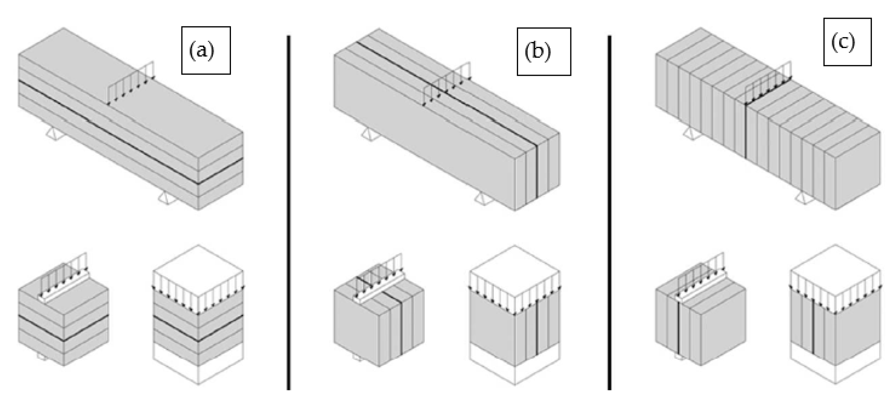
Zareiyan and Khoshnevis [28] suggested that the choice of test method should have loading like the stress conditions of the actual 3D printed structure. Therefore, interlayer bond strength tests for the printed structure are generally configured with the direction of its printing, i.e., perpendicular, longitudinal, and lateral, as shown in Figure 2 [21]. In 3DPC, the interlayer bond strength tests are mostly tensile, while some authors have considered shear, compression and bending (3-point) tests. It is noteworthy that the test results from these different tests differ significantly and similar variation in the results has been noticed for cast specimens; for example, Beushausen and Alexander [28] found mechanical adhesion in tension differs from the mechanical adhesion in shear, while Momayez et al. [29] noted that the slant shear test method produced results eight times higher than those of pull-off and splitting tests (the latter two tests had similar results).
The above-highlighted interlayer bond strength measurement methods (Figure 1) reflect a mechanical macrostructure level. It is sometimes scientifically necessary to investigate the interface at a microstructural level and, therefore, microscopic investigations of the layer interface are reviewed in this paper along with specimen preparation methods. Due to lack of standardized method for determining the interlayer bond strength of 3D printed concrete [30], researchers have adopted different methods for specimen preparation and testing. The different approaches reported in the literature along with different materials influence the final results and, therefore, an exact explanation for weak bond strength cannot currently be provided.
This section focuses on different mechanical measurement methods for evaluating bond strength properties, microscale test methods to characterize the microstructural performance of the interlayer, and specimen preparation methods such as test age, test sample slicing/extraction from printed part, layer number(s) in the test sample, etc.
2.1. Mechanical (Macroscale) Measurement Methods
The test methods reported in the literature include tensile (direct and split), flexural (three-point bending), shear, and compression tests. Some authors [30] used combination of these test methods, while others [25,31,32] use one of these methods. More details about these test methods are expatiated in the following sub-sections.
2.1.1. Tensile Test—Direct and Split
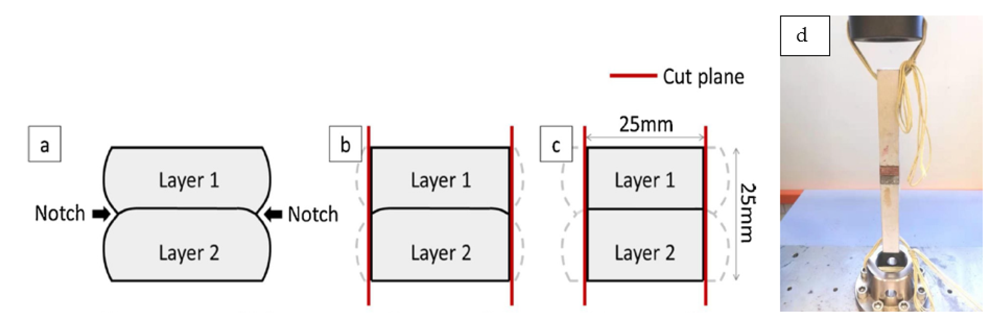
He et al. [31] conducted direct tensile test on 3D printed cementitious paste according to ASTM D7234 [33] standard with a unique sample preparation approach shown in Figure 3. Three layers were printed, and the bottom layer was cut off before testing. The side-notches were cut off partially or fully to avoid stress concentration. The result shows that the sample processing improved the bond strength with no major difference between part- and full-notch removals (Figure 3b,c).
Chen et al. [32] used printed part of two layers to investigate the bond strength of 3D printed limestone-calcined clay-based cementitious material and compared its performance with mold-casted samples. Similar to He et al. [31], formed notches due to deformation was avoided by choice of extraction (see Figure 4a); however, new notches were created to ensure failure at the interface zone, as shown in Figure 4b. Sanjayan et al. [34] also tested the bond strength with intentionally created notches while special care was taken to minimize eccentricity.
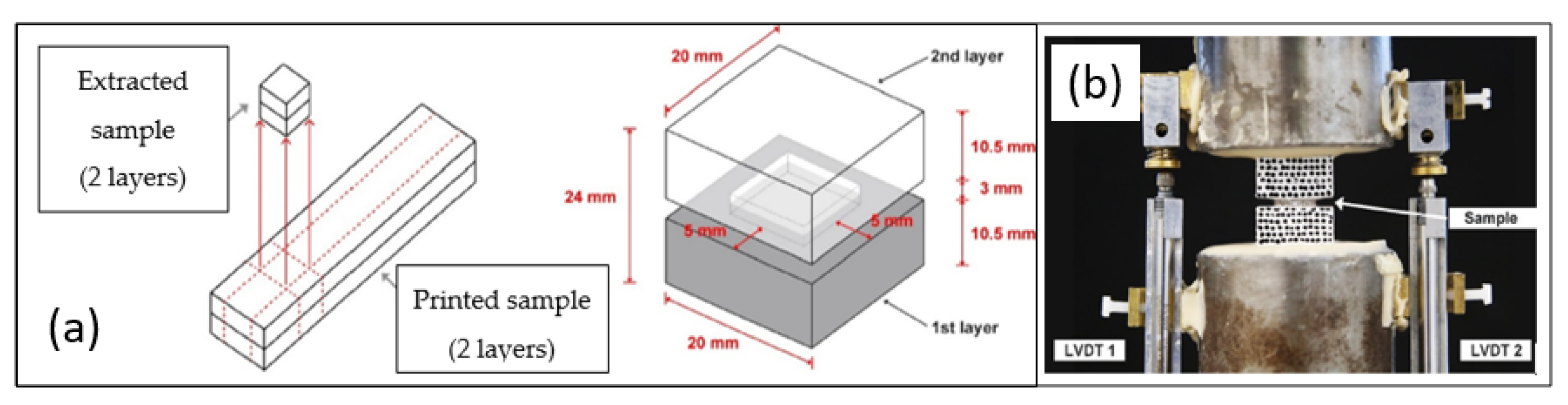
Wolf et al. [21] used split tensile test to evaluate the interlayer bond strength using 40 mm × 40 mm × 40 mm samples following NEN-EN 12390-6 [35] standard. Unlike earlier studies, the test sample used by Wolf et al. [30] contained up to five layers. Ma et al. [30] also used samples containing multiple layers for testing direct tensile bond strength, as shown in Figure 5. The focus of the study was on an applied interlayer mortar (containing calcium sulphoaluminate cement, cellulose fiber, and limestone filler) for improving bonding. At least six replicate samples were tested in this study.
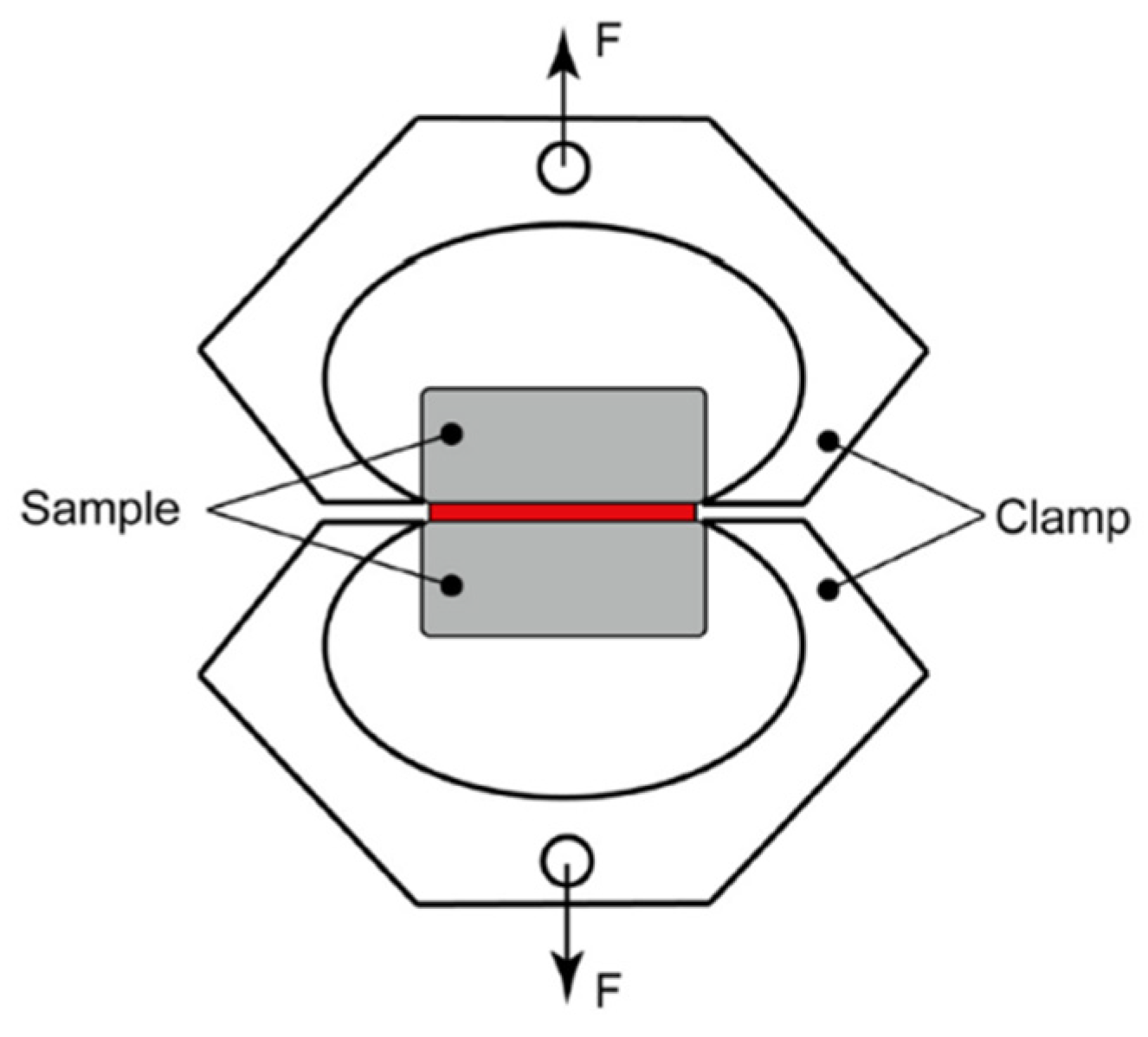
Another direct tensile test setup involving a clamp system (Figure 6) was used by Marchment et al. [36] to test the use of extruded paste as an interlayer bonding material. 3DPC samples were tested at 7 days with at least 9 replicate samples. It is believed that the test setup allowed for an even distribution of stress [36].
Unlike earlier geometries, Lee et al. [37] used cylindrical cores for the direct tensile test of 3D printed concrete at 28 days according to BS EN 14488-4 [38]. The geometry was purposefully used after X-ray computed microscopy (XCT) scans and the results suggest that the pore volume at the interlayer did not directly affect the failure of the mortar. This indicates that the point of higher pore is not necessarily the plane of debonding/fracture, which is in line with the findings of Chen et al. [32], where the authors used notches to ensure that the plane of failure occurs at the interlayer [37].
Similarly, a preliminary study by Zareiyan and Khoshnevis [28] found that uniaxial tensile test sometimes caused failures outside of the bond area and misalignment which can cause large scattering of results. The authors, therefore, adopted splitting tensile test using two-layer 100 mm cube specimens. This size is bigger than the 40 mm cubes used by Wolf et al. [21] and Geng et al. [39] for the splitting tensile test. Panda et al. [40] on the other hand, used sliced 40 mm cubes (without any form of processing) of two layers for direct tensile test after 28 days of curing. In another study, Panda et al. [23] used 50 mm cube slices for a direct tensile test. Instead of cube shape, Lee et al. [41] used four-layer 3DPC cylindrical samples (50 mm diameter and 140 mm high) to measure bond strength at 7, 14 and 28 days.
From the above and as seen in later sections, some authors allowed for multilayer samples for the interlayer bond test while others used two-layer samples. Zareiyan and Khoshnevis [28] evaluated the effects of single and four-layer splitting tensile (and compressive) test samples on 75 min, 3, 7 and 28 days and found that using multilayer sample can increase the interlayer bond strength by 10–30%. This has implications on the interpretation of results on the choice of sample geometry.
The aforementioned discussion, coupled with the use of varying concrete age and numerous replicate test samples by various authors underscore the fact that processing of samples and the test methodologies require standardization to ensure uniformity and consistency for digital concrete construction. It can be suggested that the material preparation approaches for bond strength should mimic the 3D printed part properties; for example, the processing technique used by He et al. [31] (side-notch removal in Figure 3) relates very well to subtractive post-processing approaches (such as milling) suggested by Buswell et al. [42].
2.1.2. Flexural or Bending Test
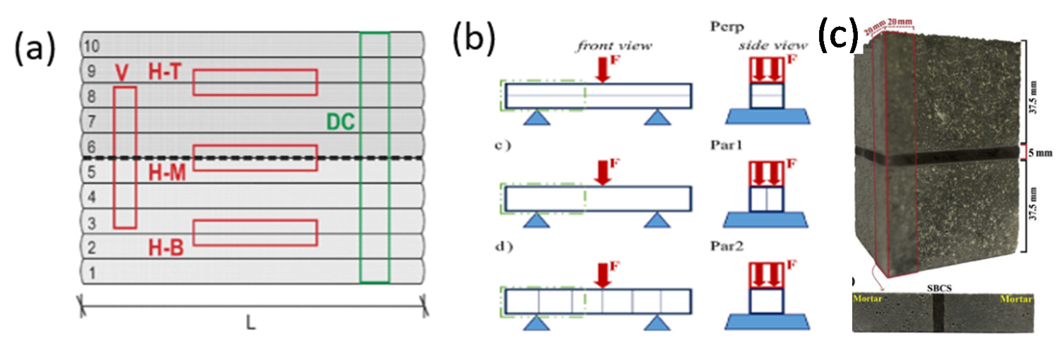
Kloft et al. [26] used three-point bending test to compare the interlayer bond strength of 3D sprayed concrete (3DSC) with 3D printed concrete and reported that 3DSC outperforms the 3D printed concrete. The samples were extracted and tested from printed parts, as shown in Figure 7a,b.
It should be noted that vertical (V) and horizontal (H-T, H-M and H-B) sliced samples were used for the bending tests, parallel and perpendicular to printing directions, respectively (two layers were allowed in the parallel direction test). Nerella et al. [22] also used three-point bending tests to evaluate the interlayer bond strength of 3DPC using samples extracted similar to Kloft et al. [26]. Testing ages of the samples were 1 and 28 days. Different sample extraction was used by Hosseini et al. [43], as shown in Figure 7c, with the three-point bending load applied at the interface.
Unlike previous authors, Wolf et al. [21] used sliced samples (40 mm × 40 mm × 160 mm) containing four layers for a three-point bending test with a similar loading setup shown in Figure 2 following NEN-EN 196-1 [44]. Dressler et al. [45] also used three-point bending test for 3D printed sample at 28 days concrete age using 20 mm × 20 mm × 125 mm sample; however, there was no information about the number of layers. More recently, Sanjayan et al. [34] tested 25 mm × 30 mm × 250 mm of two-layer specimens in three-point bending in both perpendicular and lateral directions for characterizing the inter layer bond strength.
2.1.3. Compression Test
The use of a simple compressive test for interlayer bond strength is arguable. For example, Nerella et al. [22] recognizes the inappropriateness of compressive test and suggested shear tests that inadvertently incorporate compression. Some authors [25,28] suggested that compressive loading in the direction parallel to the interlayer serves as an acceptable measure of interlayer bond strength while other authors [21,26,34,40] incorporating compressive test as part of interlayer bond studies are rather silent on its choice to evaluate interlayer bond. All these findings reiterate the fact that there is a need for standardization of the test method. Some studies in the literature using compressive test are summarized in this section.
Kloft et al. [26] conducted compression test (in both perpendicular and parallel directions) using 25 mm cubes, cured for 14 days, without explicitly stating if it is a measure of interlayer bond strength or not. Nerella et al. [22] also carried out compression test using fractured ends of the three-point bending samples and stated that the choice of compressive test for the interlayer bond is still of general interest for the overall design performance of 3D printed parts. Other researchers used compression test (without explicit mention of its choice for interlayer strength test) include Wolfs et al. [21], Panda et al. [23], and Sanjayan et al. [34]. Zareiyan and Khoshnevis [25,28] acknowledged the compression test in the printing direction as an adhesion test.
2.1.4. Shear Test
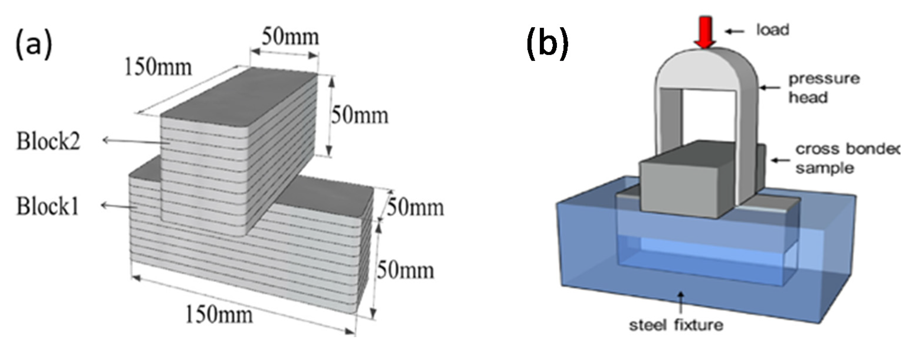
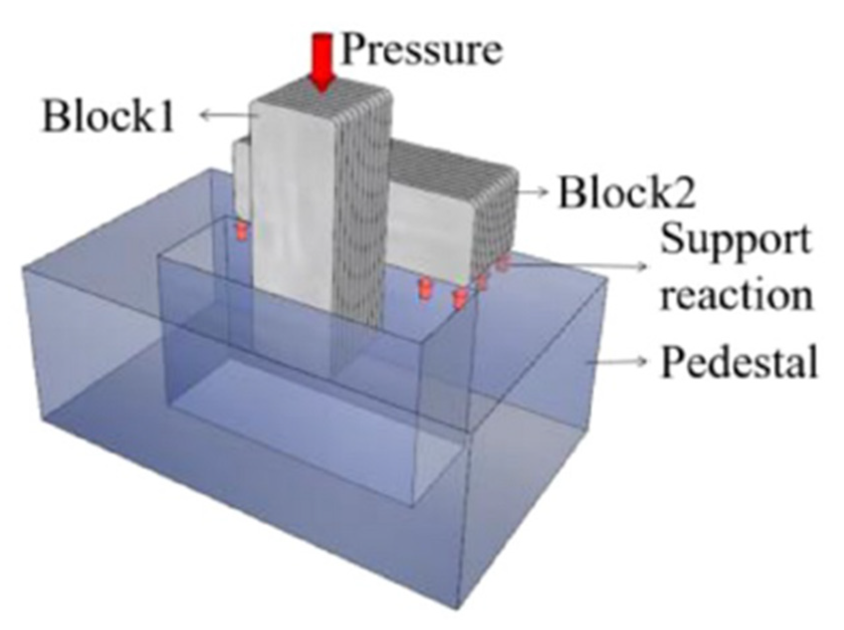
The use of the shear test to evaluate the bond strength is scarce in the literature. Ma et al. [30] and Wang et al. [46] tested shear bond strength between the interlayer of 3DPC using similar sample geometry shown in Figure 8. Ma et al. [30] stated that the shear test setup (Figure 10) is more practical because it is directly related to the stability of the structure.
From the reviewed studies, the choice of mechanical test method(s) (tensile, flexure/bending, shear and compression) is usually the onus of the researcher, with most studies giving no rationale for the choice of test method. It is noted there is no standard for determining the bond strength, and it is difficult to create a direct tensile experimental procedure that ensures no eccentricity and that every tested specimen will fail at the interface.
2.2. Microscale Characterisation
The discussion so far on the testing for adhesion of 3DPC layers focuses on evaluating the mechanical performance. Besides this basis of evaluation, an understanding of the factors influencing mechanical performance at the contact interface between the substrate and overlay layers is necessary. Therefore, microscale investigation of the interface properties using XCT, scanning electron microscopy (SEM), energy dispersive spectroscopy (EDS), X-ray diffraction (XRD), optical microscopy, flatbed scanner and nano-indentation is discussed in this section. It should be noted that some authors used combination of two or more methods for the microscale investigation.
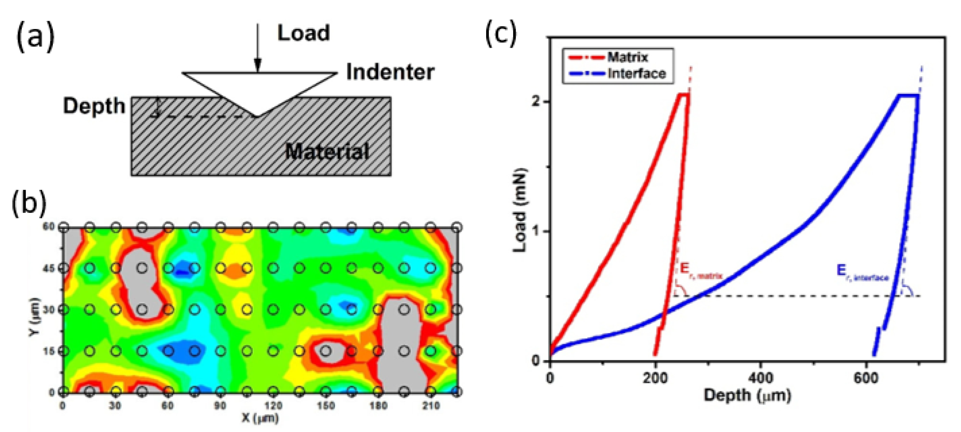
Geng et al. [39] used XCT scans for 40 mm × 40 mm × 80 mm samples, stating that only macro pores higher than 0.1 mm are detectable. Smaller scaled pores (micro pores) not detectable by XCT were investigated by scanning electron microscopy (SEM). The interfacial area of split samples was cut into smaller pieces (10 mm × 5 mm × 5 mm), ultrasonically cleaned for 15 min and immersed into ethanol alcohol for 3 days to stop hydration to analyses the interfacial pore structure at different scales. The SEM magnification was chosen in such a way that the micro interface between the hydration products can be clearly analyzed. The micromechanical performance of the interface was further characterized by nano-indentation. Since this often requires a smooth surface, the SEM samples were afterwards impregnated with epoxy resin and ground using SiC paper. After that, polished for 30 min with diamond suspensions and cleaned in ethanol to remove polishing residues for indentation testing, as shown in Figure 9.
Van Der Putten et al. [47] carried out microstructural characterization campaign of 3DPC. These include laser beam for surface roughness of the printed filament, pore size distribution using MIP for two-layer core, 2D air voids (macro pores) analysis (measured by RapidAir457 device) of the printed filament, XCT scans of the two-layer cores and SEM analysis of the cores. All these were used to understand the interlayer bond behavior of 3DPC. Chen et al. [32] also used XCT scans for the air void analysis on drilled two-layer cylindrical samples at 7 days, noting that pores only larger than 50 µm can be detected while Kloft et al. [26] used XCT for multi-layered cores drilled through the full height of the printed parts shown in Figure 7a.
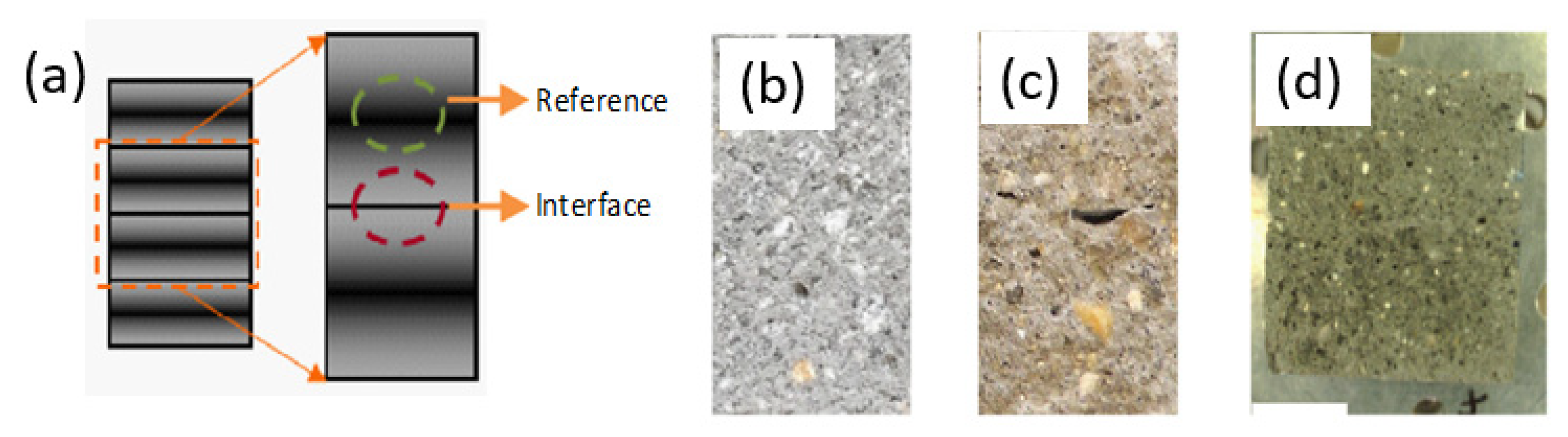
Nerella et al. [22] used the SEM facility in low vacuum mode for characterizing the interface of two printed layers and compared the performance with a reference (microstructure of a core taken from a single layer) as shown in Figure 10. The authors noted that for the sample preparation, sawing through the specimen distorts the interface due to pseudo-polishing by the saw blades and therefore splitting force can be applied vertically along the print direction to obtain a fresh broken surface (Figure 10b–d).
Ma et al. [30] used a combination of SEM, energy dispersive spectroscopy (EDS) and X-ray diffraction (XRD) to study the hydration at the interlayer that includes the specially applied bonding mortar highlighted in Section 2.1.1. A SEM with a maximum spatial resolution of 1 µm was applied to analyze voids, pores and faults at the broken interface after tensile/shear testing. The voids, pores and faults were explained further with EDS and XRD for the hydration products.
Hosseini et al. [43] sliced the thin layer of the fractured interlayer surface from a bending test. They used SEM to capture the morphology and microstructure, coupled with EDS for elemental composition. Dressler et al. [45] combined both XCT scans for evaluating the interface tortuosity and a digital microscope for the micro-roughness of the printed layer. Vertical deviation of the surface from an ideal smooth surface was determined according to DIN EN ISO 4287 [48]. Panda et al. [40] used an optical microscope to investigate the interlayer microstructure and fracture surfaces after tensile bond tests for qualitative assessment.
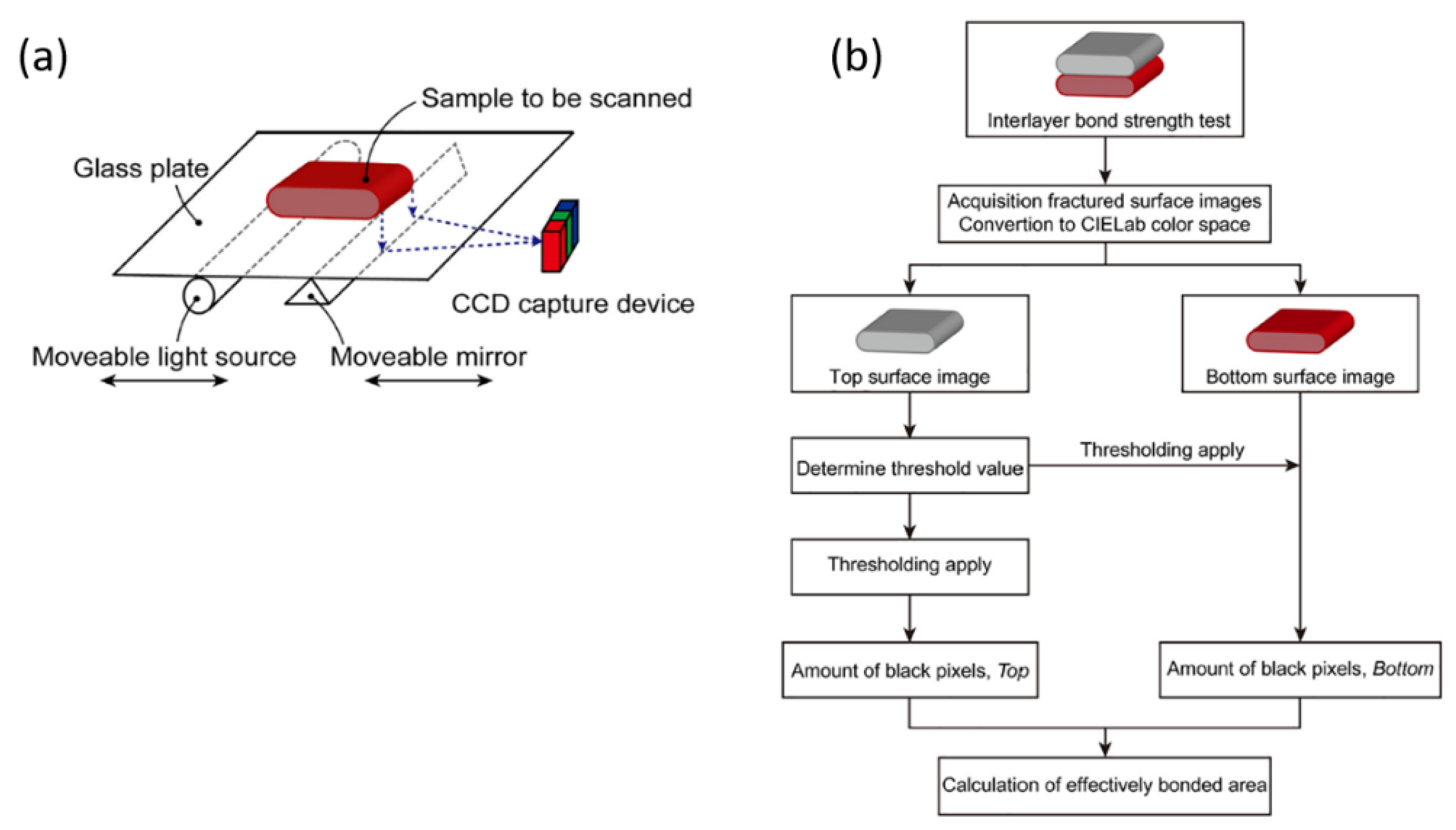
Marchment et al. [36] collected the fractured samples from the tensile testing and longitudinally scanned by a flatbed scanner for image acquisition and analysis of the bond area for clear boundaries of voids and areas of contact. The authors stated that the common perpendicular slicing by other authors provides only a very small section of the interface to be analyzed at a time. The scanning process and flow diagram for the image thresholding to calculate the effective bond area is shown in Figure 11.
It can be noted from the summarized methods that the tests were either applied on the (sliced/cored in situ) bonded layers or fractured parts at the interface of the printed layers after mechanical testing (such as tensile and bending tests). As pointed out by Nerella et al. [22], the preparation/processing of the samples (such as polishing, grinding, impregnation, etc.) can influence the result and care must be taken to interpret the results. These approaches for characterization also require standardization.
3. Factors Affecting Interlayer Bond Strength
The literature reveals interlayer bond strength in 3DCP is related to many factors such as ‘time gap between the layers’, ‘surface moisture’, ‘structuration rate’, ‘printing speed’, ‘nozzle stand-off distance’, etc. This section summarizes existing results on effect of these parameters on bond strength of 3D printed concrete.
3.1. Effect of Time Interval between the Two Successive Layers
In cementitious materials, time is an important factor as the phases of hydration process, also known as concrete maturity, reach at different stages with time. In 3DCP, the time gap between two successive layers causes loss of surface moisture which can affect the bond strength. However, temperature and humidity also play a vital role in moisture level present on the deposited layers.
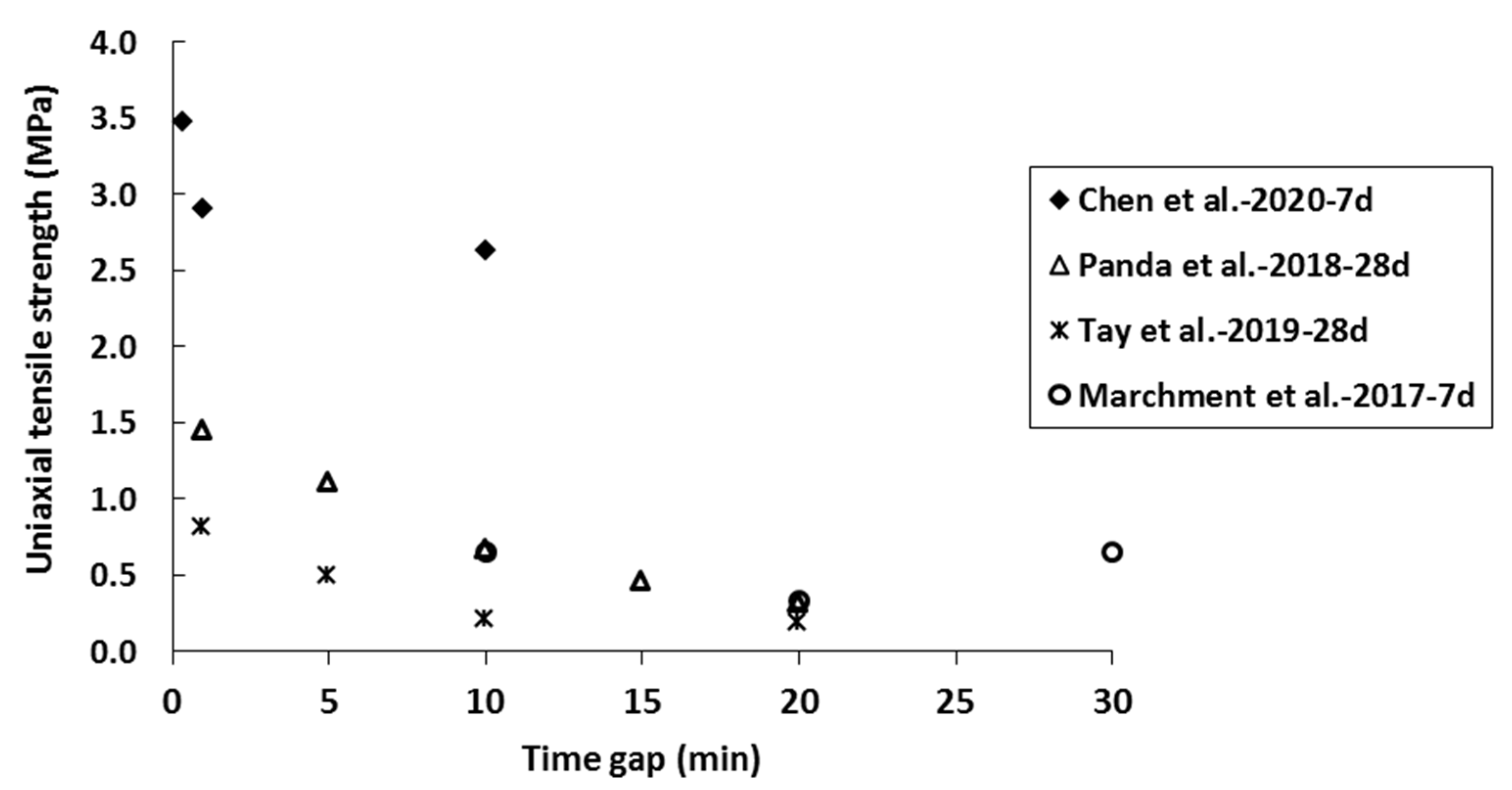
The effect of the printing time gap on uniaxial tensile strength of 3D printed samples, reported in recent papers is summarized and illustrated in Figure 12.
Chen et al. [32] investigated the effect of time interval (20 s, 1 min, 10 min) between two successive layers on bond strength of 3D printed concrete. Except for the 20 s time gap, strength reduction by 4% and 13% was observed for printed samples with time gaps of 1 min and 10 min, respectively, compared to casted samples. A similar (strength reduction) trend was reported by Wolfs et al. [21] for the time gaps of 15 s, 4 h and 24 h, and Sanjayan et al. [34] for time gaps of 10 and 20 min. Panda et al. [23] tested the influence of different time gaps (1, 5, 10, 15, and 20 min) on the bond strength of 3D printed geopolymer mortar samples with two layers of extruded filament. A reduction in bond strength was reported for more extended time gaps than 1 min. It was found that for time gaps of 5, 10, 15 and 20 min, the strength reduction was 23%, 55%, 67%, and 76%, respectively. This behavior was attributed to increase in structuration rate of the geopolymer which caused poor interlayer bonding and, thus, reduced tensile bond strength.
A comparative study of different moisture content on the surface of 3D printed and mold cast samples was done by Sanjayan et al. [34]. The experimental findings revealed that the moisture content was higher in 3D printed sample and moisture content could be reduced up to a certain time gap between two layers (0 to 20 min), and, after that, it can increase again (maximum level of moisture found at 30 min). On the other hand, moisture was found to increase with increase in time for the casted concrete The higher moisture was attributed to the continuous bleeding of the material within the 30 minutes’ delay. Low moisture level was linked to low inter-layer strength of the samples.
Keita et al. [50] investigated the relative water loss (i.e., the ratio of evaporated water and initial water content in the material) from the first layer as a function of resting time and linked with bond strength of 3DCP samples. They used wind tunnel for drying the printed layer for different time intervals and thus obtained different relative water loss in the first layer. Water loss was constantly measured for the first layer in the tunnel before placing the second layer. It was found that for relative water loss of 0.1% (here, the time was 10 min), there was no significant change in the interface bond strength. However, strength was reduced gradually as the relative water loss increased. For 1% of water loss, strength was reduced around 40% than the reference strength.
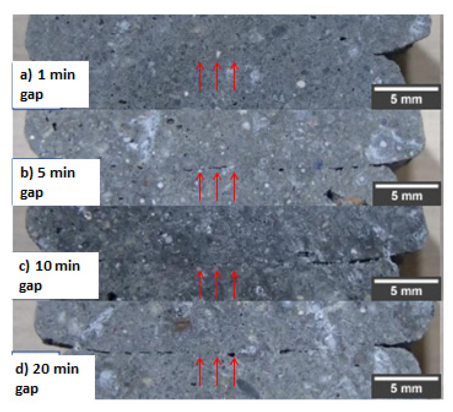
The effect of the printing time gap on interface condition of the extruded layers is pictorially presented in Figure 13 [8]. A longer printing time gap produces cavities and voids in the interface and filament layer [8]. It may be noted the arrows in Figure 13 represent the location of the interface of the two-track layers. It is evident that cavities and voids dominate in the interface when printing time gap increases. This is because of the setting time of the fresh material where the hydration reactions of binders consume the mixed water and solidify the composite, resulting in a reduced moisture availability on the surface of the printed layers. Typically, dry cementitious materials form a weak zone at the joint and, thus, the bond strength reduces significantly. It should be worth mentioning that in 3DCP, unlike in conventional concrete, no external force or vibration is applied to compact the material after deposition. This is also another reason for forming a weak zone between the joints of the printed layers. Nevertheless, with continuous research work and development in this area, researchers have proposed several techniques to overcome this dispute discussed in the subsequent sections. These techniques are discussed in Section 4.
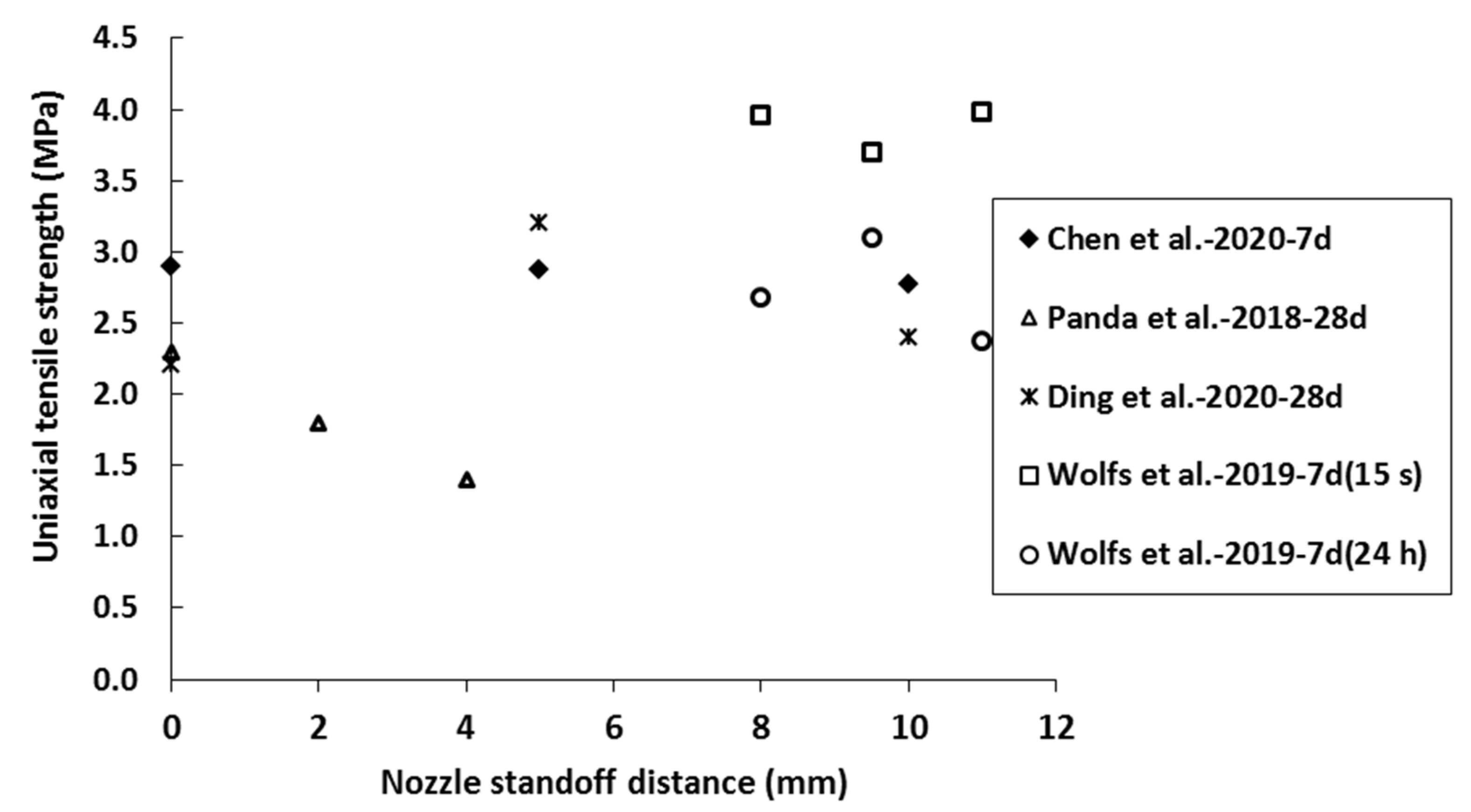
3.2. Effect of Nozzle Stand-Off Distance
Nozzle stand-off distance can also play a vital role in the bond strength of 3DPC. Lower bond strength can be obtained for higher stand-off distance. About 23% and 35% reduction in bond strength was found for the printed samples when the stand-off distance increased from 0 mm to 2 mm and 4 mm [23]. When stand-off distance increases, large cavities can be formed in the interface and contribute to lower mechanical and durability properties [22]. Figure 14 illustrates the effect of nozzle standoff distance on the uniaxial tensile strength reported by researchers [21,23,32,51].
Ding et al. [51] concluded that the optimum standoff distance is around 5 mm. Compared to the bond strength for 5 mm nozzle height, the reduction in strengths for 0 mm and 10 mm was about 31.1% and 24.2%, respectively. However, no noticeable difference in the strength was found for three different nozzle heights (8 mm, 9.5 mm, and 11 mm) at two different printing time intervals (15 s and 24 h) in a study conducted by Wolfs et al. [21]. It was concluded that the effect of the nozzle height and interlayer strength is more pronounced for materials with initial more yield strength and structuration rate [13,21]. However, the physics behind this strength reduction due to nozzle stand-off height is not yet clear and not discussed rigorously by the researchers, necessitating more studies.
3.3. Effect of Printing Speed
The printing speed also plays a vital role in the success of 3D printing. For a specific 3D printable mix design, an optimum printing speed is required for successful printing. This optimized speed may vary with mix designs as rheological properties of cementitious mixes are quite different due to variation in source materials, mix formulations.
The effect of printing speed on the bond strength was studied in [23,46,52]. At the printing speed of 1.7 cm/s, the loss of bond strength of the samples printed at 10 min and 60 min time gap was about 58% and 75%, respectively, compared with 0 min. At a printing speed of 3 cm/s, these reductions were 89% and 97% [46], respectively. At a low printing time gap (1 min), there was no significant difference in the average bond strength of 3D printed samples printed at different speeds [23]. The roughness of the printed layer also depends on the printing speed. Typically, a higher speed (without changing material flow rate) will create lower roughness in the layer surface and may lead to lower bond strength [52]. Higher printing speed (not matched with equivalent volume flow rate) also creates higher porosity and bigger voids inside the printed materials [52], which can affect mechanical and durability properties of the structure. Overall, for the same material and nozzle size, a higher printing speed may lead to irregularities in the track shape leading to structural integrity and bonding problems.
Another effect of increased printing speed (with change in material flow rate-pump speed) is increased shearing of the material. This was identified by Weng et al. [20] to improve the cohesion and adhesion of the filaments. As the pump speed increases, the thixotropic behavior weakens, and materials need more time to recover their original structure. This delay in recovering time gives a better chance for the subsequent layer to bond well with the existing layer. However, further research is needed considering mixes with different initial state/structures.
3.4. Effect of Mix Design and Curing Conditions
The success of 3DCP requires a high-performance cementitious mix with controlled material property especially at its fresh stage. As no formwork is used in 3DCP, thus a material with proper yield stress and viscosity is required to ensure no deformability in the existing layer once a successive layer is deposited over it. For better printability, it is required to have a material of high initial static viscosity which can undergo microstructural changes to become less viscous by deflocculation under applied force (i.e., force generated during pumping), but rebuilds or re-flocculates to become highly viscous once it has been extruded and comes to rest [53]. This behavior is known as thixotropy. Panda et al. [40] modified thixotropy by adding nanoclay and confirmed higher bond strength for lower thixotropic material. Recently, Weng et al. [20] attempted to change the thixotropy index of the material by adding superplasticizer, which affected surface moisture content of the printed specimens. It was concluded that with increase in superplasticizer dosage, the thixotropic index decreases, and surface moisture content increases; consequently, the interlayer bond strength increases. The authors also investigated the impact of different curing conditions on the interlayer bond strength. It was shown that underwater curing (among air, standard and water) has the highest impact. Air curing had the lowest impact.
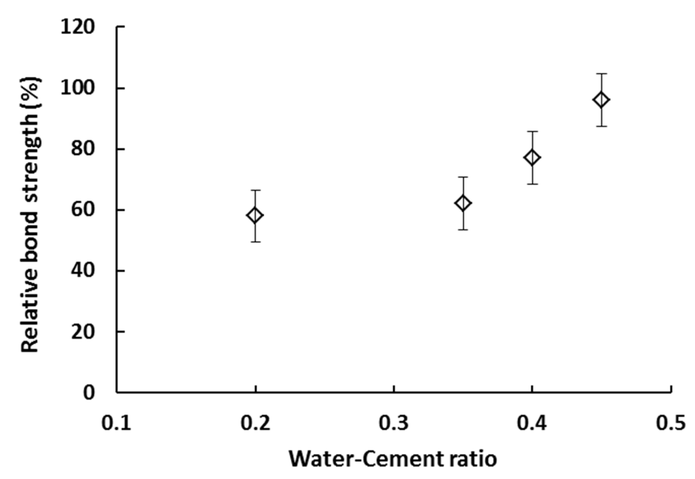
Keita et al. [50] tested the bond strength of two successive layers of printed samples made from a different water-to-cement ratio (w/c) of 0.2, 0.35, 0.4, and 0.45, as shown in Figure 15. The result suggested that the relative bond strength (i.e., ratio between the average bond strength of printed and cast samples) decreases with w/c ratio. For cast concrete, it is known that low w/c leads to a decrease in the voids and the permeability of concrete. However, in 3DCP, this may reduce the ability of printed layers to feed the surface with moisture, which can negatively affect the bond strength between the two interface layers. Furthermore, it is known that the lower w/c concrete forms a dry surface compared to that of higher w/c. This drier surface may lead to a weak zone between the two interlayers of 3D printed samples.
4. Methods for Improving Bond Strength
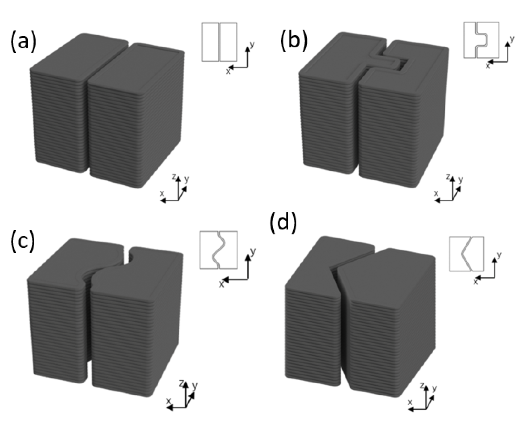
Many researchers have attempted to improve the bond strength of 3D printed concrete samples by modifying their bonding mechanism via mechanical and chemical bonding. Zareiyan and Khoshnevis [28] used an interlocking technique for improving the inter-layer bond strength of 3D printed mortar samples, where different sizes (0, 6.35, 12.7 and 19 mm) of grooves were mechanically created between the deposited layers. The results indicated that the samples with the interlocking size of 12.7 mm show 17% higher bond strength than the samples without any interlocking. In a recent study, Wang et al. [54] investigated the bonding performance of 3D printed concrete with four different interlocking configurations designed with “I”, “π”, “s” and “V” shaped forms and three cementitious composites as shown in Figure 16. The epoxy-based adhesive material provided high bond strength based on the strength analysis, while V-type interlocking produces the best tensile and shear resistance.
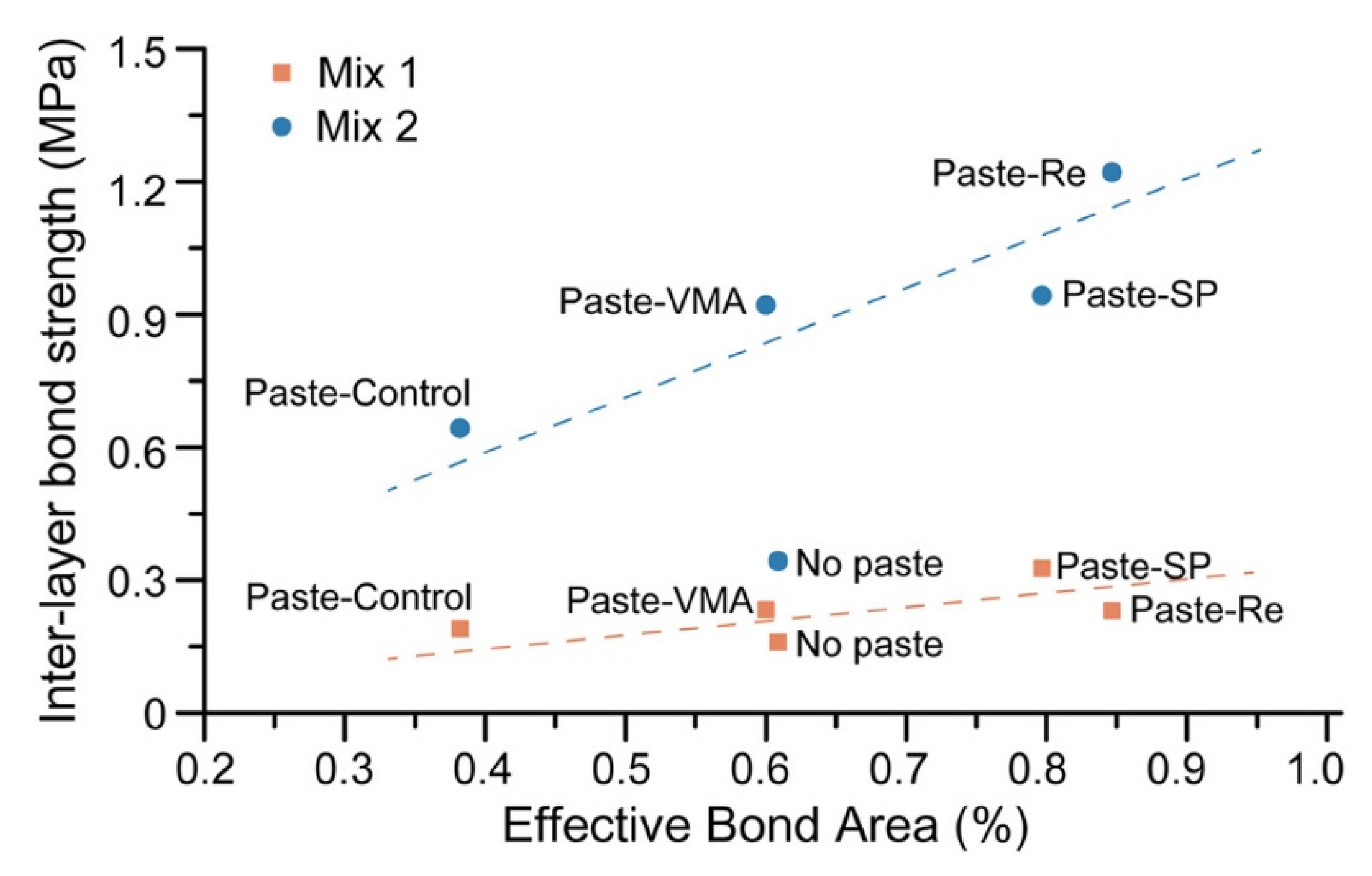
Marchment et al. [36] attempted to strengthen the interlayer bond by increasing the surface moisture retention, and it was achieved by applying cementitious paste at the interface. It was concluded that the pastes containing a superplasticizer or retarder could increase the bond strength. Figure 17 shows a strong relationship between the effective bond area and the interlayer strength. The application of a cementitious paste between layer depositions increases the effective bonding area, and the bond strength increased to 60%. It can be noted that Mix 1 and Mix 2 have the same composition, except there was no addition of color pigment in Mix 1.
A similar analogy was presented by Roussel et al. [13] while investigating distinct-layer casting problems in self-compacting concrete. The result shows that shear strength decreases with an increase in thixotropy of the mixes. Thixotropy and/or structuration rate of the first layer was responsible for re-mixing layers by the stresses generated at the interface between the two layers. This means that less thixotropic material can be prepared to improve the bond strength via re-initiating flow in the first layer due to the weight of the second layer and flow shear stress.
Muthukrishnan et al. [55] applied microwave heating just before the placement of layers, and for optimum conditions, the inter-layer bond strength was increased by 132%. This was achieved due to an increase in the poly-condensation reaction between the filaments activated by microwave, despite the loss of surface moisture. The authors also reported low bond strength for microwave heating beyond the optimum time (i.e., 10 s).
In a recent study, different bonding agents such as water, cement paste without a spreader, polymer solution, and cement strengthener (an adhesion admixture) were sprayed on the printed layer, and their effect on the bond strength was investigated [56]. Except for water, bond strength was increased for all other agents than the reference material without any bonding agent. Hosseini et al. [43] adopted polymer adhesive as the bonding agent to enhance the interlayer bond strength, and their experiment results presented a considerable increase in the interlayer bond strength. The two-fold rise in interlayer bond strength and chemical cohesion proved that their method could enhance bonding between adjacent layers.
5. Conclusions and Future Perspectives
A concise investigation of the interlayer bond strength property of 3D printed concrete is reported in this paper. Due to the layer-wise extrusion of fresh concrete material, printed concrete manifests anisotropic mechanical properties and this interlayer property is regarded as the weakest joint in most publications. This represents an important research gap, and according to authors, improving bond strength can minimize the anisotropic effect. Therefore, researchers have investigated the bond strength by varying the material composition, the time gap between layers and printing parameters. Most of the studies were conducted in a controlled environment, and factors affecting the bond strength such as material properties, time gap and process parameters were reported. In addition, different testing methods were reported in this review work for characterizing the bond behavior and mechanism affecting the bond strength such as surface moisture, roughness, bonding area, process parameters and material early age properties. The exact reason for lack of bond strength varies in all publications. From the strategies reviewed in this paper, it was found that a 26% improvement in the bond strength has been achieved using mechanical interlocking patterns [28], whereas a 60% improvement was reported [36] by increasing the effective bond area. However, at this stage it is difficult to conclude the best way for bond strength improvement in 3DCP, as the specimen size and testing methods are not uniform. It is recommended that, during post-processing of specimens (sawing and notching), any visible crack should be avoided prior to the bond strength testing and notching should be carried out in such a way that it should have less influence on the peak stress.
Future research should focus on the following:
- Standardizing the specimen preparation process and test method for measuring the bond strength of 3D printed concrete;
- Investigation of the mechanisms responsible for weak bond strength via modelling and advanced characterization techniques;
- Investigation of the long-term influence of poor bond strength on durability and fire properties;
The weak interface of 3D concrete printing could also be harnessed to improve mechanical and flexural properties of concrete-like brittle materials as demonstrated in [59]. Moreover, similar to other 3D printing processes [60,61], data-driven tools, such as machine learning and artificial intelligence, can be applied to concrete printing technique to find the correlations between nozzle shape, material, process parameters as well as interlayer bond strength properties.
Author Contributions
Conceptualization and methodology, S.C.P., B.P.; data analysis, J.T.K., S.C.P., and B.P.; data collection, A.J.B., and M.J.M.; writing—original draft, A.J.B., J.T.K., S.C.P., M.J.M. and B.P.; All authors have read and agreed to the published version of the manuscript.
Funding
The corresponding author express his gratitude to the Indian Institute of Technology Guwahati, Assam, India.
Institutional Review Board Statement
Not applicable.
Informed Consent Statement
Not applicable.
Data Availability Statement
Not applicable.
Acknowledgments
Not applicable.
Conflicts of Interest
The authors declare no conflict of interest.
References
- Du Plessis, A.; Babafemi, A.J.; Paul, S.C.; Panda, B.; Tran, J.P.; Broeckhoven, C. Biomimicry for 3D concrete printing: A review and perspective. Addit. Manuf. 2021, 1823. [Google Scholar] [CrossRef]
- Europe’s Largest 3D-Printer Prints an Entire Two-Story House. Available online: https://www.designboom.com/architecture/kamp-c-3d-prints-two-story-house-08-17-2020/ (accessed on 30 October 2020).
- The World’s Largest 3D Printed Concrete Bridge Is Completed in Shanghai. Available online: https://www.designboom.com/architecture/shanghai-3d-printed-concrete-bridge-jcda-01-21-19/ (accessed on 30 October 2020).
- A Five-Storey Apartment in China. Available online: http://www.winsun3d.com (accessed on 17 February 2021).
- Buswell, R.A.; De Silva, W.L.; Jones, S.Z.; Dirrenberger, J. 3D printing using concrete extrusion: A roadmap for research. Cem. Concr. Res. 2018, 112, 37–49. [Google Scholar] [CrossRef]
- Soltan, D.G.; Li, V.C. A self-reinforced cementitious composite for building-scale 3D printing. Cem. Concr. Comp. 2018, 90, 1–13. [Google Scholar] [CrossRef]
- Nematollahi, B.; Xia, M.; Sanjayan, J.; Vijay, P. Effect of type of fiber on inter-layer bond and flexural strengths of extrusion-based 3D printed geopolymer. Mater. Sci. Forum 2018, 939, 155–162. [Google Scholar] [CrossRef]
- Tay, Y.W.D.; Ting, G.H.A.; Qian, Y.; Panda, B.; He, L.; Tan, M.J. Time gap effect on bond strength of 3D-printed concrete. Virtual Phys. Prototyp. 2019, 14, 104–113. [Google Scholar] [CrossRef]
- Alchaar, A.S.; Al-Tamimi, A.K. Mechanical properties of 3D printed concrete in hot temperatures. Constr. Build. Mater. 2021, 266. [Google Scholar] [CrossRef]
- Zhang, Y.; Zhang, Y.; Yang, L.; Liu, G.; Chen, Y.; Yu, S.; Du, H. Hardened properties and durability of large-scale 3D printed cement-based materials. Mater. Struct. 2021, 54, 1–14. [Google Scholar] [CrossRef]
- Moelich, G.M.; Kruger, J.; Combrinck, R. Plastic shrinkage cracking in 3D printed concrete. Compos. Part B Eng. 2020, 200. [Google Scholar] [CrossRef]
- Van Der Putten, J.; Snoeck, D.; De Coensel, R.; De Schutter, G.; Van Tittelboom, K. Early age shrinkage phenomena of 3D printed cementitious materials with superabsorbent polymers. J. Build. Eng. 2021, 35. [Google Scholar] [CrossRef]
- Roussel, N.; Cussigh, F. Distinct-layer casting of SCC: The mechanical consequences of thixotropy. Cem. Concr. Res. 2008, 38, 624–632. [Google Scholar] [CrossRef]
- Cicione, A.; Kruger, J.; Walls, R.S.; Van Zijl, G. An experimental study of the behavior of 3D printed concrete at elevated temperatures. Fire Saf. J. 2020. [Google Scholar] [CrossRef]
- Pham, L.; Tran, P.; Sanjayan, J. Steel fibres reinforced 3D printed concrete: Influence of fibre sizes on mechanical performance. Constr. Build. Mater. 2020, 250. [Google Scholar] [CrossRef]
- Radojičić, V.; Radulović, R.; Tarić, M.; Jović, S. The influence of the steel fibers on improvement of mechanical characteristic of concrete. Mech. Based Des. Struct. Mach. 2020, 1–11. [Google Scholar] [CrossRef]
- Zhang, Y.; Zhang, Y.; She, W.; Yang, L.; Liu, G.; Yang, Y. Rheological and harden properties of the high-thixotropy 3D printing concrete. Constr. Build. Mater. 2019, 201, 278–285. [Google Scholar] [CrossRef]
- Jeong, H.; Han, S.J.; Choi, S.H.; Lee, Y.J.; Yi, S.T.; Kim, K.S. Rheological property criteria for buildable 3D printing concrete. Materials 2019, 12, 657. [Google Scholar] [CrossRef] [PubMed] [Green Version]
- Chua, C.K.; Leong, K.F. 3D Printing and Additive Manufacturing: Principles and Applications (with Companion Media Pack) of Rapid Prototyping, 4th ed.; World Scientific Publishing Company: Toh Tuck Link, Singapore, 2014. [Google Scholar]
- Weng, Y.; Li, M.; Zhang, D.; Tan, M.J.; Qian, S. Investigation of interlayer adhesion of 3D printable cementitious material from the aspect of printing process. Cem. Concr. Res. 2021, 143. [Google Scholar] [CrossRef]
- Wolfs, R.J.M.; Bos, F.P.; Salet, T.A.M. Hardened properties of 3D printed concrete: The influence of process parameters on interlayer adhesion. Cem. Concr. Res. 2019, 119, 132–140. [Google Scholar] [CrossRef]
- Nerella, V.N.; Hempel, S.; Mechtcherine, V. Effects of layer-interface properties on mechanical performance of concrete elements produced by extrusion-based 3D-printing. Constr. Build. Mater. 2019, 205, 586–601. [Google Scholar] [CrossRef]
- Panda, B.; Paul, S.C.; Mohamed, N.A.N.; Tay, Y.W.D.; Tan, M.J. Measurement of tensile bond strength of 3D printed geopolymer mortar. Measurement 2018, 113, 108–116. [Google Scholar] [CrossRef]
- Marchment, T.; Sanjayan, J.G.; Nematollahi, B.; Xia, M. Interlayer strength of 3D printed concrete: Influencing factors and method of enhancing. In 3D Concrete Printing Technology; Butterworth-Heinemann: Oxford, UK, 2019; pp. 241–264. [Google Scholar] [CrossRef]
- Zareiyan, B.; Khoshnevis, B. Interlayer adhesion and strength of structures in Contour Crafting-Effects of aggregate size, extrusion rate, and layer thickness. Autom. Constr. 2017, 81, 112–121. [Google Scholar] [CrossRef]
- Kloft, H.; Krauss, H.W.; Hack, N.; Herrmann, E.; Neudecker, S.; Varady, P.A.; Lowke, D. Influence of process parameters on the interlayer bond strength of concrete elements additive manufactured by Shotcrete 3D Printing (SC3DP). Cem. Concr. Res. 2020, 134. [Google Scholar] [CrossRef]
- Beushausen, H.; Alexander, M.G. Bond strength development between concretes of different ages. Mag. Concr. Res. 2008, 60, 65–74. [Google Scholar] [CrossRef]
- Zareiyan, B.; Khoshnevis, B. Effects of interlocking on interlayer adhesion and strength of structures in 3D printing of concrete. Autom. Constr. 2017, 83, 212–221. [Google Scholar] [CrossRef]
- Momayez, A.; Ehsani, M.R.; Ramezanianpour, A.A.; Rajaie, H. Comparison of methods for evaluating bond strength between concrete substrate and repair materials. Cem. Concr. Res. 2005, 35, 748–757. [Google Scholar] [CrossRef]
- Ma, G.; Salman, N.M.; Wang, L.; Wang, F. A novel additive mortar leveraging internal curing for enhancing interlayer bonding of cementitious composite for 3D printing. Constr. Build. Mater. 2020, 244. [Google Scholar] [CrossRef]
- He, L.; Chow, W.T.; Li, H. Effects of interlayer notch and shear stress on interlayer strength of 3D printed cement paste. Addit. Manuf. 2020, 36. [Google Scholar] [CrossRef]
- Chen, Y.; Jansen, K.; Zhang, H.; Rodriguez, C.R.; Gan, Y.; Çopuroğlu, O.; Schlangen, E. Effect of printing parameters on interlayer bond strength of 3D printed limestone-calcined clay-based cementitious materials: An experimental and numerical study. Constr. Build. Mater. 2020, 262. [Google Scholar] [CrossRef]
- ASTM D7234. Standard Test Method for Pull-off Adhesion Strength of Coatings on Concrete Using Portable Pull-off Adhesion Testers; ASTM International: West Conshohocken, PA, USA, 2019. [Google Scholar]
- Sanjayan, J.G.; Nematollahi, B.; Xia, M.; Marchment, T. Effect of surface moisture on inter-layer strength of 3D printed concrete. Constr. Build. Mater. 2018, 172, 468–475. [Google Scholar] [CrossRef]
- NEN-EN 12390-6. Testing Hardened Concrete—Part 6: Tensile Splitting Strength of Test Specimens; The Royal Netherlands Standardization Institute: Delft, The Netherlands, 2009. [Google Scholar]
- Marchment, T.; Sanjayan, J.; Xia, M. Method of enhancing interlayer bond strength in construction scale 3D printing with mortar by effective bond area amplification. Mater. Des. 2019, 169. [Google Scholar] [CrossRef]
- Lee, H.; Kim, J.H.J.; Moon, J.H.; Kim, W.W.; Seo, E.A. Correlation between pore characteristics and tensile bond strength of additive manufactured mortar using X-ray computed tomography. Constr. Build. Mater. 2019, 226, 712–720. [Google Scholar] [CrossRef]
- BS EN 14488-4. Testing Sprayed Concrete. Bond Strength of Cores by Direct Tension; British Standard Institution: London, UK, 2005. [Google Scholar]
- Geng, Z.; She, W.; Zuo, W.; Lyu, K.; Pan, H.; Zhang, Y.; Miao, C. Layer-interface properties in 3D printed concrete: Dual hierarchical structure and micromechanical characterization. Cem. Concr. Res. 2020, 138. [Google Scholar] [CrossRef]
- Panda, B.; Mohamed, N.A.N.; Paul, S.C.; Bhagath Singh, G.V.P.; Tan, M.J.; Šavija, B. The effect of material fresh properties and process parameters on buildability and interlayer adhesion of 3D printed concrete. Materials 2019, 12, 2149. [Google Scholar] [CrossRef] [Green Version]
- Lee, H.; Kim, J.H.J.; Moon, J.H.; Kim, W.W.; Seo, E.A. Evaluation of the mechanical properties of a 3D-printed mortar. Materials 2019, 12, 4104. [Google Scholar] [CrossRef] [PubMed] [Green Version]
- Buswell, R.A.; da Silva, W.L.; Bos, F.P.; Schipper, H.R.; Lowke, D.; Hack, N.; Roussel, N. A process classification framework for defining and describing Digital Fabrication with Concrete. Cem. Concr. Res. 2020, 134. [Google Scholar] [CrossRef]
- Hosseini, E.; Zakertabrizi, M.; Korayem, A.H.; Xu, G. A novel method to enhance the interlayer bonding of 3D printing concrete: An experimental and computational investigation. Cem. Concr. Comp. 2019, 99, 112–119. [Google Scholar] [CrossRef]
- NEN-EN 196-1. Methods of Testing Cement—Part 1: Determination of Strength; The Royal Netherlands Standardization Institute: Delft, The Netherlands, 2016. [Google Scholar]
- Dressler, I.; Freund, N.; Lowke, D. The effect of accelerator dosage on fresh concrete properties and on interlayer strength in shotcrete 3D printing. Materials 2020, 13, 374. [Google Scholar] [CrossRef] [Green Version]
- Wang, L.; Tian, Z.; Ma, G.; Zhang, M. Interlayer bonding improvement of 3D printed concrete with polymer modified mortar: Experiments and molecular dynamics studies. Cem. Concr. Comp. 2020, 110. [Google Scholar] [CrossRef]
- Van Der Putten, J.; Deprez, M.; Cnudde, V.; De Schutter, G.; Van Tittelboom, K. Microstructural characterization of 3D printed cementitious materials. Materials 2019, 12, 2993. [Google Scholar] [CrossRef] [PubMed] [Green Version]
- DIN EN ISO 4287. Geometrical Product Specifications (GPS)—Surface Texture: Profile Method—Terms, Definitions and Surface Texture Parameters; Deutsches Institut für Normung: Berlin, Germany, 2010. [Google Scholar]
- Marchment, T.; Xia, M.; Dodd, E.; Sanjayan, J.; Nematollahi, B. Effect of delay time on the mechanical properties of extrusion-based 3D printed concrete. In Proceedings of the International Symposium on Automation and Robotics in Construction, Taipei, Taiwan, 28 June–1 July 2017; IAARC Publications: Waterloo, ON, Canada, 2017; Volume 34. [Google Scholar]
- Keita, E.; Bessaies-Bey, H.; Zuo, W.; Belin, P.; Roussel, N. Weak bond strength between successive layers in extrusion-based additive manufacturing: Measurement and physical origin. Cem. Concr. Res. 2019, 123. [Google Scholar] [CrossRef]
- Ding, T.; Xiao, J.; Zou, S.; Wang, Y. Hardened properties of layered 3D printed concrete with recycled sand. Cem. Concr. Comp. 2020, 113. [Google Scholar] [CrossRef]
- Van Der Putten, J.; De Schutter, G.; Van Tittelboom, K. The effect of print parameters on the (micro) structure of 3D printed cementitious materials. In RILEM International Conference on Concrete and Digital Fabrication; Springer: Zurich, Switzerland, 2018; Volume 19, pp. 234–244. [Google Scholar]
- Paul, S.C.; van Zijl, G.P.A.G.; Tan, M.J.; Gibson, I. A review of 3D concrete printing systems and materials properties: Current status and future research prospects. Rapid Prototyp. J. 2018, 24, 784–798. [Google Scholar] [CrossRef] [Green Version]
- Wang, L.; Liu, Y.; Yang, Y.; Li, Y.; Bai, M. Bonding performance of 3D printing concrete with self-locking interfaces exposed to compression–shear and compression–splitting stresses. Addit. Manuf. 2021, 42. [Google Scholar] [CrossRef]
- Muthukrishnan, S.; Ramakrishnan, S.; Sanjayan, J. Effect of microwave heating on interlayer bonding and buildability of geopolymer 3D concrete printing. Constr. Build. Mater. 2020, 265. [Google Scholar] [CrossRef]
- Weng, Y.; Li, M.; Wong, T.N.; Tan, M.J. Synchronized concrete and bonding agent deposition system for interlayer bond strength enhancement in 3D concrete printing. Autom. Constr. 2021, 123. [Google Scholar] [CrossRef]
- Seifan, M.; Samani, A.K.; Berenjian, A. Bioconcrete: Next generation of self-healing concrete. Appl. Microbiol. Biotechnol. 2016, 100, 2591–2602. [Google Scholar] [CrossRef] [Green Version]
- De Schutter, G.; Lesage, K. Active control of properties of concrete: A (p) review. Mater. Struct. 2018, 51, 1–16. [Google Scholar] [CrossRef]
- Moini, M.; Olek, J.; Youngblood, J.P.; Magee, B.; Zavattieri, P.D. Additive Manufacturing and Performance of Architectured Cement-Based Materials. Adv. Mater. 2018, 30. [Google Scholar] [CrossRef] [Green Version]
- Ng, W.L.; Chan, A.; Ong, Y.S.; Chua, C.K. Deep learning for fabrication and maturation of 3D bioprinted tissues and organs. Virtual Phys. Prototyp. 2020, 15, 340–358. [Google Scholar] [CrossRef]
- Panda, B.N.; Garg, A.; Shankhwar, K. Empirical investigation of environmental characteristic of 3-D additive manufacturing process based on slice thickness and part orientation. Measurement 2016, 86, 293–300. [Google Scholar] [CrossRef]
Figure 1.
Bond testing methods: (A) direct tensile; (B) splitting; (C) wedge splitting; (D) slant shear; (E) torsion; (F1–3) modified shear. Reprinted with permission from ref. [28]. Copyright 2017 Elsevier B.V.
Figure 1.
Bond testing methods: (A) direct tensile; (B) splitting; (C) wedge splitting; (D) slant shear; (E) torsion; (F1–3) modified shear. Reprinted with permission from ref. [28]. Copyright 2017 Elsevier B.V.

Figure 2.
Test load direction for 3DPC in relation to the printing direction: (a) perpendicular; (b) crossed; (c) lateral. Reprinted with permission from ref. [21]. Copyright 2019 Elsevier Ltd.
Figure 2.
Test load direction for 3DPC in relation to the printing direction: (a) perpendicular; (b) crossed; (c) lateral. Reprinted with permission from ref. [21]. Copyright 2019 Elsevier Ltd.

Figure 3.
Specimen processing: (a) printed sample; (b) part-notch removal; (c) full-notch removal and (d) uniaxial test setup. Reprinted with permission from ref. [31]. Copyright 2020 Elsevier B.V.
Figure 3.
Specimen processing: (a) printed sample; (b) part-notch removal; (c) full-notch removal and (d) uniaxial test setup. Reprinted with permission from ref. [31]. Copyright 2020 Elsevier B.V.

Figure 4.
(a) Direct tensile test sample and (b) setup used by Chen et al. [32]. Reprinted with permission from ref. [32]. Copyright 2020 Elsevier Ltd.

Figure 5.
(a) Sample geometry and (b) tensile test setup in the study of Ma et al. [30]. Reprinted with permission from ref. [30]. Copyright 2020 Elsevier Ltd.

Figure 6.
A schematic direct tensile test setup for interlayer bond strength by Marchment et al. [36]. Reprinted from ref. [36].

Figure 7.
(a) Sample extraction (from Kloft et al. [26]), drilled core (DC) are for computed tomography scans in Section 2.2 (b) test setups (from Nerella et al. [22]), dotted lines are the parts used for compression tests in Section 2.1.3; (c) sample extraction by Hosseini et al. [43]. Reprinted with permission from ref. [22,26,43]. Copyright 2020 Elsevier Ltd.

Figure 8.
Shear test setup (Ma et al. [30] and Wang et al. [46]) with sample geometry in Figure 5a. Reprinted with permission from ref. [30,46]. Copyright 2020 Elsevier Ltd.

Figure 9.
(a) Nano-indentation of 3DPC fractured part; (b) modulus mapping of interfacial area; (c) typical micromechanical performance. Reprinted with permission from ref. [39]. Copyright 2020 Elsevier Ltd.
Figure 9.
(a) Nano-indentation of 3DPC fractured part; (b) modulus mapping of interfacial area; (c) typical micromechanical performance. Reprinted with permission from ref. [39]. Copyright 2020 Elsevier Ltd.

Figure 10.
(a) Sample extraction for SEM investigation; (b) saw-cut surface; (c) split surface; (d) typical specimen for SEM. Reprinted with permission from ref. [22]. Copyright 2019 Elsevier Ltd.
Figure 10.
(a) Sample extraction for SEM investigation; (b) saw-cut surface; (c) split surface; (d) typical specimen for SEM. Reprinted with permission from ref. [22]. Copyright 2019 Elsevier Ltd.

Figure 11.
(a) Schematics of flatbed scanning procedure and (b) flow diagram for evaluating the effective bonded area. Reprinted from ref. [36].
Figure 11.
(a) Schematics of flatbed scanning procedure and (b) flow diagram for evaluating the effective bonded area. Reprinted from ref. [36].

Figure 12.
Effect of printing time gap in uniaxial tensile strength of 3D printed objects (reproduced from [8,23,32,49]).

Figure 13.
Effect of printing time gap on the interface of the two layers of 3D printed samples. Reprinted from ref. [8].
Figure 13.
Effect of printing time gap on the interface of the two layers of 3D printed samples. Reprinted from ref. [8].

Figure 14.
Impact of nozzle standoff distance in uniaxial tensile strength of 3D printed objects (reproduced from [21,23,32,51]).

Figure 15.
Relative bond strength of 3D printed sample as a function of w/c. Reprinted with permission from ref. [50]. Copyright 2019 Elsevier Ltd.
Figure 15.
Relative bond strength of 3D printed sample as a function of w/c. Reprinted with permission from ref. [50]. Copyright 2019 Elsevier Ltd.

Figure 16.
Interlocking types for 3D printing blocks with (a) “I”; (b) “π”; (c) “s” and (d) “V” shaped interlocking. Reprinted with permission from ref. [54]. Copyright 2021 Elsevier B.V.
Figure 16.
Interlocking types for 3D printing blocks with (a) “I”; (b) “π”; (c) “s” and (d) “V” shaped interlocking. Reprinted with permission from ref. [54]. Copyright 2021 Elsevier B.V.

Figure 17.
Relation between interlayer bond strength versus the effective bond area. (Mix 2 and Mix 1 have same composition except Mix 1 without color pigments). Reprinted from ref. [36].
Figure 17.
Relation between interlayer bond strength versus the effective bond area. (Mix 2 and Mix 1 have same composition except Mix 1 without color pigments). Reprinted from ref. [36].

Publisher’s Note: MDPI stays neutral with regard to jurisdictional claims in published maps and institutional affiliations. |
© 2021 by the authors. Licensee MDPI, Basel, Switzerland. This article is an open access article distributed under the terms and conditions of the Creative Commons Attribution (CC BY) license (https://creativecommons.org/licenses/by/4.0/).
Share and Cite
MDPI and ACS Style
Babafemi, A.J.; Kolawole, J.T.; Miah, M.J.; Paul, S.C.; Panda, B. A Concise Review on Interlayer Bond Strength in 3D Concrete Printing. Sustainability 2021, 13, 7137. https://0-doi-org.brum.beds.ac.uk/10.3390/su13137137
AMA Style
Babafemi AJ, Kolawole JT, Miah MJ, Paul SC, Panda B. A Concise Review on Interlayer Bond Strength in 3D Concrete Printing. Sustainability. 2021; 13(13):7137. https://0-doi-org.brum.beds.ac.uk/10.3390/su13137137
Chicago/Turabian StyleBabafemi, Adewumi John, John Temitope Kolawole, Md Jihad Miah, Suvash Chandra Paul, and Biranchi Panda. 2021. "A Concise Review on Interlayer Bond Strength in 3D Concrete Printing" Sustainability 13, no. 13: 7137. https://0-doi-org.brum.beds.ac.uk/10.3390/su13137137
Note that from the first issue of 2016, this journal uses article numbers instead of page numbers. See further details here.