
Circular Construction Process: Method for Developing a Selective, Low CO2eq Disassembly and Demolition Plan


1
Department of Civil Engineering, University of Salerno, 84084 Fisciano, Italy
2
AEC Freelance, 80121 Naples, Italy
*
Authors to whom correspondence should be addressed.
Sustainability 2021, 13(16), 8815; https://0-doi-org.brum.beds.ac.uk/10.3390/su13168815
Submission received: 6 July 2021
/
Revised: 22 July 2021
/
Accepted: 30 July 2021
/
Published: 6 August 2021
(This article belongs to the Special Issue Data and the Built Environment: Reconciling Resources and Information for a Sustainable Living)
Abstract
:With the increasing focus on the construction sector (e.g., following the European Green Deal initiative) with the aim to reduce emissions by 55% by 2030 (compared to 1990 levels), as well as achieve full decarbonisation by 2050, the built environment remains a strategic domain for the R&I (Research and Innovation) agenda. Indeed, the building and construction sector is the main contributor to greenhouse gas emissions (39% of global emissions as of 2018), highlighting the need to start a process of decarbonisation of this sector. The overall reduction in the environmental impact of building materials is achieved by establishing sustainable continuity between the end-of-life phase of the building and the production phase of individual building components. In particular, with reference to the end-of-life phase of the building (BS EN 15978: 2011), the Minimum Environmental Criteria foresee the preparation of a plan for the disassembly and selective demolition of the building, which allows the reuse or recycling of materials, building components and prefabricated elements used. According to the guidelines of a low-carbon construction design, which takes into account a circular economy, the following thesis deals with a methodological proposal to study “dry” construction systems (wood and steel). In particular, the study intends to reach the development of such an elaboration by carrying out an assessment of the environmental impact of a process of selective disassembly and demolition of steel building systems. The model is developed on the basis of a reading of the level of sustainability of emblematic case studies, appropriately identified, i.e., ‘quality’ architectures, built with ‘dry’ (steel) building systems.
1. Introduction
On 4 March 2020, the European Commission, as we have seen, proposed the adoption of the first European Climate Act [1], with the aim of enshrining in law the achievement of climate neutrality by 2050 and ensuring that all EU policies and sectors play their part. The EU’s strategy for achieving climate neutrality by 2050 is the European Green Deal [2]. The European Green Deal, an integral part of the European Commission’s strategy to implement the 2030 Agenda and the UN Sustainable Development Goals [3], aims to transform the EU into a fair and prosperous society with a modern, resource-efficient economy that generates no net greenhouse gas emissions in 2050 and where economic growth is decoupled from resource use [2]. In order to achieve climate neutrality by 2050 and decoupling of economic growth from resource use, the European Green Deal, through “A new action plan for the circular economy. For a cleaner and more competitive Europe” [4], which takes up the actions already implemented in 2015 through the “EU Action Plan for the Circular Economy” [5], promotes the extension of the circular economy to traditional economic actors, with targeted interventions for resource-intensive sectors such as building and construction. In a circular economy, the value of products, materials and resources is maintained as long as possible, and waste production is minimised, thus helping to avoid irreversible damage to climate, biodiversity and air, soil and water pollution caused by consuming resources at a rate that exceeds the Earth’s capacity to renew them [5]. The actions proposed by the European Green Deal support the circular economy at every stage of the value chain: production, consumption, repair and remanufacturing, waste management and feeding secondary raw materials back into the economy. A prominent role in the circular economy is played by waste management and the feeding back of secondary raw materials into the economy [5]. Proper waste management leads to higher recycling and reuse rates, resulting in the return of valuable materials to the economy, as opposed to an inefficient system where most recyclable waste ends up in landfills or incinerators, with potentially damaging effects on the environment and significant economic losses [5]. In terms of volume, construction and demolition waste is one of the largest sources of waste in Europe, making the building and construction sector one of the sectors that should be given special attention. A significant reduction of construction and demolition waste is entrusted by the European Green Deal to a sustainable product policy [2], which prioritises the reduction and reuse of products, elements and materials before recycling. Reuse prevents the impacts associated with the production of new products by reintroducing into the production cycle products, building elements and materials with the same original functions and performance. Recycling activities, on the other hand, require physical or chemical transformation activities, with consequent energy consumption, before products, elements and building materials with different functions and performances from the original ones are put back into the production cycle.
In order to maximise the potential for reuse of building components, with consequent reintroduction of materials into the production cycle, the end-of-life phase of the life cycle of a building body plays a key role. The boundaries of the end-of-life phase are provided by BS EN 15978:2011 [6], which proposes a schematic, in modules, of the phases of the life cycle of a building or construction product, for the presentation and reporting of environmental data and results. The end-of-life phase of a building or construction product is characterised by the C, end-of-life stage (Figure 1). The latter refers to the energy used and the environmental impact, in terms of greenhouse gas emissions, generated by all activities of demolition, deconstruction, dismantling of a building or construction product (C1, Deconstruction–demolition), the transport of demolition waste from the construction site to an appropriate storage or disposal site (C2, Transport), the sorting, collection and treatment of demolition waste (C3, Waste processing) and the disposal of demolition waste at an appropriate disposal site (C4, Disposal).
The overall reduction of the environmental impacts of construction materials, as seen, requires a circular life-cycle approach, passing through the reintroduction of materials into the production cycle, which requires the implementation of reuse activities in an end-of-life phase of a building body. Phase D, Benefits and loads beyond system boundary (Figure 1), covers the net benefits and loads resulting from the reuse or recycling of materials (secondary raw materials) that, in their end-of-waste state, replace other materials (primary raw materials) in another product system, or resulting from energy recovery through materials (energy carriers) that, in their end-of-waste state, replace other materials (fuels) in an energy recovery process [6,7].
Maximising the reuse potential of building components, however, requires a synergy between a reversible design phase, capable of creating easily disassembled building organisms, and, as indicated in Italian Ministerial Decree 11 October 2017—article 2.3.7 [8], an end-of-life phase of the building characterised by the preparation of a plan for disassembly and selective demolition, the latter being able to “disassemble” the individual building components, so as to preserve and not worsen their residual performance, and destine them to a second life cycle, thus establishing a sustainable continuity between the end-of-life phase (decommissioning and disposal of the building product) and the production phase of the individual building components, which is the principle underlying a circular economy and a circular approach to the life cycle of a building or construction product.
This study investigates modules C and D of the BS EN 15978:2011 scheme [6] (Figure 1), because, as we have to aspire to the closed-loop model (cradle to cradle), technical options for reuse and recycling in the management of construction material flows are indispensable. Therefore, the two key phases to achieve an effective closing of the loop are design and demolition. The present study intends to investigate phases C and D, as the design choice has been set to investigate steel building systems which result, from previous studies on the topic, to be more prone to disassembly operations at the end of life and with lower embedded CO2 emissions (compared to more traditional building systems) [9,10].
2. State of the Art
The past approach has focused on the reduction of operational energy, due to its higher energy impact in the overall life cycle. In fact, thanks to the strategies applied in recent years in the energy retrofit sector, the critical issues related to the operational energy consumption of existing buildings and the related greenhouse gas emissions have definitely decreased. However, the strategy of reducing the operational energy of the building stock through the construction of better performing buildings has not been sufficient to trigger a trend reversal [8,9]. These activities, while improving in one respect, have led to a significant increase in the demand for new, higher-performance building materials, ignoring the side effects related to embodied energy and associated greenhouse gas emissions. The current approach focuses on strategies to reduce the environmental impacts related to the whole life cycle of the building, with particular reference to the reduction of embodied energy. The most common building systems in the construction sector have been investigated with the aim of identifying a predisposition to reduce the embodied energy content of each technological system. Numerous researches have been carried out with the aim of providing an innovative contribution to the design with regard to the possibilities of mitigation of embodied energy (EE) and embodied carbon (EC). In particular, Sicignano et al. [10] aims to identify construction systems with less EE and CE, both in the case of using primary materials and in the case of using secondary materials, i.e., materials derived from the recovery and recycling of construction and demolition waste or obtained by reintroducing, in the production cycle, the residues of production processes. The case study in Sicignano et al. [10] is represented by a project of reconstruction of a residential area, for which three possible structural solutions were hypothesised with three different materials: concrete, steel and wood. An interesting result, in terms of reduced energy consumption and reduced environmental impact, emerged from the estimation of the amount of EE and CE in the case of using secondary materials, which highlighted the enormous advantages obtainable from the use of “light” dry technological systems (steel and wood) compared to traditional “wet” technological systems (masonry and concrete). In fact, ‘light’ dry technology systems achieved the greatest reduction in EE and CE values. This result is due to the greater predisposition of dry technological systems, which we can distinguish in “light” (steel and wood) or “massive” (precast concrete), to disassembly activities at the end of the building life, which in turn implies high percentages of reusability and recyclability. However, the opportunity to reintroduce building components into the production cycle, resulting in a further reduction of embodied energy and embodied carbon, makes “light” dry technology systems preferable to “massive” dry technology systems. The latter systems allow the reintroduction of building components into the production cycle with different functions and performances from the original ones and only through recycling activities, with consequent additional energy consumption. The building components of “light” dry technology systems, on the other hand, have the potential to be reintroduced into the production cycle with the same original functions and performance. Profiles for steel beams and columns generally have a very high reuse value since the sections of the profiles are characterised by standard dimensions; therefore, they can be easily reused in new buildings or civil engineering works [11].
De Wolf et al. [12] highlighted the environmental impact of downsizing and reconditioning activities during the reuse of steel components for the construction of a new building. The assessment was carried out by comparing a reference building composed of reused steel elements with the same building composed of newly produced steel elements. As a first step, the amount of embedded carbon was estimated for both buildings using the Inventory of Carbon and Energy. For the reference building composed of reused elements, the energy required during the selective deconstruction, the emissions due to transport and the emissions due to the resizing and reconditioning activities of the components to be reused were taken into account. In recent years, some research has developed effective strategies for overcoming this limitation, adopting a predominantly project-based approach. A strategic solution, useful for several life cycles, is represented by the improvement of the design of assembly and disassembly operations, which allows one to optimise the assembly and disassembly time and to optimise the amount of materials that can be reused in the future. Denis et al. [13] developed a method to analyse the interdependence between the elements of a building organism in order to define which elements are recovered and which are lost in a dismantling process. The parameters influencing the potential recovery of an element, on which the method is based, refer to the elements to be recovered and the connections between the elements. The parameters referring to the elements are accessibility, transportability and resistance to wear. The parameters referring to the connections are reversibility and disassembly time. In the literature there are clear difficulties in assessing the benefits of reusing materials from renovation, recovery or demolition activities for the construction of new buildings. These difficulties are represented by the inability to quantify both the emissions generated by dismantling activities and the emissions generated by downsizing and reconditioning activities of materials to be reused. Furthermore, the methods and tools developed so far have only a theoretical imprint; there is therefore a lack of application to case studies and an almost complete lack of focus on virtuous building systems (steel structures).
Huang et al. [14] analysed the main constraints hindering construction and demolition waste management in China through a series of interviews involving groups of stakeholders relevant to the C&DW industry (academics and researchers, construction and demolition companies, treatment and recycling companies). The analysis of recycling and reuse activity revealed two limitations that are common to C&DW management in Europe
- -
- Absence of a developed market for recycled or reusable construction materials;
- -
- The absence of quality standards for recycled or reusable products.
However, they weigh most heavily on reuse activities. Reuse activities, unlike recycling activities, require a large number of design and performance requirements to be met in order to reintroduce materials into the production cycle, which can contribute to increasing costs and reducing demand for reusable materials.
Densley Tingley et al. [15], through a literature review and a series of interviews with people involved throughout the steel supply chain for the construction sector, highlighted the limitations of steel reuse. The limitations that emerged from the research, in order of frequency, are analysed below: Lack of information on the existing structure and materials; need for a selective demolition process; and difficulty in finding reusable building components. The absence of a waste management plan and a demolition scenario design may result in the inability of recycling and reuse activities to compensate for both the impacts of using a large amount of mechanical equipment and the impacts of landfilling.
In particular, literature has shown that there is no assessment of the benefits of reuse activities following selective deconstruction in an end-of-life phase of multi-storey steel frame buildings and a rough quantification of the greenhouse gas emissions generated by machinery and tools used during selective deconstruction.
3. Tools and Methodology
The proposed methodology consists of the following steps (Figure 2):
3.1. Phase (1) Technological Characterisation of the Work
- (1)
- Technological units and technical elements
In the first step, through the UNI 8290-1 standard [16], a classification and articulation of the technological units and technical elements into which a technological system is broken down was carried out. Within the classification scheme, all the service supply systems, all the security systems, the furnishings and the external fittings were excluded from the technological units of investigation, as they are considered invariant elements.
- (2)
- Type of building system and prevailing material sequence
In the second step, through design guidelines, for each technical element, the following was defined:
- -
- The type of construction system most commonly adopted for the realisation of an element belonging to a steel construction system;
- -
- The sequence of prevailing materials that make up the technical element.
The latter represents essential information for the subsequent definition of the types of processing necessary for disassembly and selective demolition.
- (3)
- Connection types and connection material
In the third step, through the UNI 11277:2008 standard [17], which associates each construction system with an installation technology and through design guidelines, the installation technology was defined for each prevailing material belonging to a given construction system. The latter allowed the determination of the types of connection between two consecutive prevailing materials.
3.2. Phase (2) Estimation of CO2eq Emissions
In the third step, the CO2eq emissions generated by a selective disassembly and demolition process were estimated. The CO2eq emissions are obtained from the sum of four rates:
- -
- CO2eq, 1, rate of emissions produced by the dismantling activity;
- -
- CO2eq, 2, share of emissions from scrap resulting from demolition operations;
- -
- CO2eq, 3, share of emissions from transport off-site;
- -
- CO2eq, 4, share of emissions from processing for reuse.
∑CO2eq = CO2eq, 1 + CO2eq, 2 + CO2eq, 3 + CO2eq, 4
- -
- CO2eq, 1, rate of emissions from demolition activity
In the first step, the demolition activity was divided into two demolition operations, removal of connections and transport to the ground and loading onto a lorry or articulated truck, in order to associate to each prevailing material a tool and/or machinery used for the removal of connections, according to the type of connection, and a mode of transport to the ground and loading onto a lorry, according to the dimensional characteristics of the material (weight, length).
- (a)
- Tools and/or machinery used for the removal of connections
The assignment of tools and machinery to each type of connection took place by means of the protocol [18], while the consultation of technical data sheets of manufacturers of avant-garde technologies to support professionals in the construction world made it possible to identify, for each tool and machinery, the model that best suited the type of connection (Table 1).
For the removal of connections located at a height above the work surface to support tools and machinery, the use of lifting equipment is envisaged (Table 2).
- (b)
- Modes of transport on the ground and loading onto trucks and/or articulated lorries. In order to define the methods for transporting a material or group of materials on the ground and loading them onto a lorry, mass and length ranges were defined. In addition, by consulting the data sheets of lifting equipment manufacturers, the model of the equipment used was defined for each mass range (Table 3).
In a second step (Table 4) in order to estimate the emissions generated by the use of tools, machinery and lifting equipment, their operating times were determined.
- (a)
- Seconds needed to remove connections. The seconds necessary for the removal of a single connection, for each tool and machine used, were determined through: data collected in literature, watching films corresponding to real cases, technical data sheets of tools and machines used.
- (b)
- Seconds needed for ground transport and loading onto lorries or articulated lorries
Initially, through the mode of transport, the materials were classified into seven categories, listed below:
- -
- elements of closures (upper, horizontal and lower) and partitions (horizontal, vertical, internal and external), weighing <25 kg and measuring <1.50 m, placed in metal baskets;
- -
- elements of closures (upper, horizontal and lower) and partitions (horizontal, vertical, internal and external), with dimensions >1.50 m;
- -
- elements of vertical closures and vertical external fixtures, weighing <25 kg;
- -
- vertical closure elements and vertical external fixtures, weighing >25 kg;
- -
- elements of the horizontal elevation structure, dry-assembled by clamping technique;
- -
- elements of the horizontal elevation structure, “welded”;
- -
- elements of the vertical elevation structure.
Finally, for each category, the total seconds required for transport to the ground and loading onto a lorry or articulated lorry were determined by watching films corresponding to real cases:
- -
- T0, seconds needed to connect the individual element or group of elements to the hook of the lifting device;
- -
- T1, seconds needed to transport the individual element or group of elements from its position on the worksite to its position for lifting;
- -
- T2, seconds needed to transport the individual element or group of elements from the position suitable for pulling up to a temporary storage site on the construction site;
- -
- -
- CO2eq, 2, rate of emissions from scrap resulting from demolition operations
Demolition activities can generate scrap, i.e., a proportion of material that cannot be recovered after removal because it is damaged. The CO2eq, 2 emission rate therefore corresponds to the emissions incorporated in the percentage of material that cannot be recovered after removal because it is damaged.
In the first step, the percentage of material that cannot be recovered after removal was determined. The EU-funded PROGRESS project [28], together with research [29], developed a Reusability Index, which is able to determine the percentage of reusable components of single-storey steel frame buildings by evaluating a set of parameters corresponding to a series of operations carried out during the demolition activity.
The percentage of material that cannot be recovered after removal, which passes through the determination of the reusability index, is obtained from the following relationship (Figure 4):
In a second step (Table 7), the reusability index developed by the PROGRESS project [28] and research [29] was modelled in accordance with the scope of investigation of the proposed methodology. The reusability index is characterised by:
- -
- indicators (i); demolition activities that could potentially damage the material;
- -
- weights (P); assigned to each parameter according to the influence and importance of the parameter within the recovery activity;
- -
- subindicators (s); they correspond to characteristics of the material, representative of the degree of susceptibility to damage, or to a diversification of the demolition activities;
- -
- recovery potential (%); correspond to percentages assigned to each subindicator according to the degree of damage caused to the material.
The reusability index is obtained by summing up the products of the recovery potential (%), chosen for each indicator (i) according to the subindicators (s) and their weights (p) (Figure 5):
At this point, in the third step (Figure 6), noting the percentage of material that cannot be recovered after removal because it is damaged, it is possible to estimate the rate of CO2eq, 2 emissions (Figure 6).
- -
- CO2eq,3 rate of emissions from off-site transport
The phase following the conclusion of the demolition activity involves the transport of demolition waste to appropriate storage areas, recycling or waste disposal centres. In the first step, demolition waste was classified in three macrocategories, listed below, in order to define its future destinations and the stages covered by the means of transport:
- -
- metal elements of the elevation structure and inclined partitions; this includes elements of the vertical elevation structure (pillars), horizontal (beams and joists), inclined (bracing) and all elements of inclined partitions (beams, knee beams and pillars);
- -
- Nonhazardous demolition waste; this includes all materials not covered by the first category and not marked with an asterisk (*) in the European waste list [30];
- -
- “Hazardous” or “contaminated” demolition waste; this includes all materials that are not in the first category and are marked with an asterisk (*) in the European waste list [30], or materials that have come into contact with “hazardous” materials or contaminants. In a second step, each macrocategory, depending on the type of material and the possible treatments required before reintroduction into the production cycle, was assigned possible future destinations and possible stages covered by the means of transport. The metal elements of the elevation structure, in the case of future reuse activities, require preprocessing activities (cutting, drilling, sandblasting, galvanising, and painting) before being reintroduced into the market. The plants able to provide these activities are the transformation centres, in compliance with UNI EN ISO 9001:2015, i.e., plants outside the factory or the yard, which receive basic elements from the steel producer and package elements that can be used directly on the yard. A means of transport leaving a demolition site therefore has as its first destination a transformation centre (a). The observation of 20 centres, located in Campania and Lombardy, identified through the Sicurnet.2 platform [31], has however revealed the inability of a transformation centre to provide sandblasting and galvanising activities (18 out of 20 centres are not equipped with galvanising plants). For this reason, a means of transport leaving a processing centre has as its second destination a galvanising plant (b). Once the corrosion protection system is completed, the metal elements return to the processing plant (b) in order to be stored for a new construction project (c). In the case of nonhazardous demolition waste, a means of transport leaving the demolition site, in the case of future recycling activities, has a recycling centre as its only destination. In the case of future reuse activities, a means of transport leaving the demolition site has centres run by professional dealers of construction materials from demolition activities as its only destination. In addition to providing storage areas, they provide cleaning and specialised advice. An overview of professional dealers selling building materials from old, dismantled buildings is offered by digital platforms. In the case of waste disposal activities, a transport vehicle leaving the demolition site has a waste disposal centre as its only destination. In the third step, the number of trips from the demolition site to the future destination was defined for each macrocategory. For the transport of metal elements, the number of trips is influenced by the mode of transport adopted and the type of means of transport used. The type of transport vehicle chosen, generally used for the transport of metal elements, is the articulated lorry. Knowing the capacity of the means of transport (length, volume and maximum load capacity), guidelines for the delivery and unloading of steel products [32,33] have been used to define the mode of transport. The latter involves drawing up an inventory of the steel elements to be transported, which allows the formation and subsequent loading onto the articulated lorry of groups of elements formed by the superimposition of several elements, the latter characterised by the same series (e.g., IPE) and the same dimensions. Knowing the capacity of the means of transport and the weight and volume occupied by the individual groups of elements, the number of trips is obtained by determining the number of articulated trucks that, following the gradual loading of individual groups of elements, reach the maximum load capacity or volume that can be transported. For the transport of “nonhazardous” demolition waste from the demolition site to professional dealers, the transport methods adopted and the definition of the number of trips are the same as those defined for the transport of metal elements. The only differences lie in the type of transport means chosen. For the transport of “nonhazardous” demolition waste, from the demolition site to a recycling centre, and for the transport of “hazardous” or “contaminated” demolition waste, from the demolition site to a waste disposal centre, the number of trips is influenced by the volume and weight of the demolition waste. The number of trips is obtained by determining the number of lorries that, as a result of loading fractions of material, reach the maximum transportable capacity or volume. At this point, in the fourth step, knowing the type of transport means used and defining the number of trips from the dismantling site to the future destination, it is possible to estimate the rate of CO2eq,3 emissions produced by off-site transport (Figure 7).
- -
- CO2eq,4 rate of emissions from processing activities for subsequent reuse
The metallic elements of the elev ation structure, before being put back on the market, need transformation activities necessary to achieve design and performance requirements. The facilities able to provide these activities, as we have seen, are the transformation centres, which rely on galvanising plants for the realisation of corrosion protection systems. In the first step, transformation activities have been classified in two macrocategories:
- -
- Processing activities carried out at a processing centre;
- -
- Processing activities carried out at a galvanising plant.
- -
- In a second step, for each macrocategory, the types of activities carried out and the machinery used were determined.
- -
- Processing activities carried out at a processing centre: the processing activities carried out at a processing centre and the machinery used were determined through the observation of the services offered by processing centres located in Italy.
- -
- Processing activities carried out at a galvanising plant: the processing activities carried out at a galvanising plant were determined through the observation of the services offered by galvanising plants located on the Italian territory.
In the third step, for each transformation activity, the following was defined: the type of elements to be subjected to the different activities; the number of operations to be carried out for a single element; the seconds necessary to carry out a single operation and the model of the machinery used. At this point, in the fourth step (Figure 8), knowing the transformation activities, the number of operations to be carried out and the seconds needed to carry out a single operation, it is possible to estimate the rate of CO2eq,4 emissions generated by transformation activities (Figure 8, Table 8):
3.3. Phase (3) Estimation of Waste Genera and Quantities (Verification of CAM Parameters)
In the third step, the kinds and quantities of waste produced during the whole disassembly and selective dismantling process are estimated. The estimation of waste streams is conducted by assigning each material a code from the European waste list [30], through which the nature of the material can be determined. The estimation of waste quantities is conducted by assigning each material a future destination, depending on the nature of the material and its readiness for reuse or recycling. With reference to the end-of-life phase of a building body, of particular interest is the objective set by Italian Ministerial Decree 11 October 2017—article 2.4.1.1 about “Disassembly” [8]: at least 50% by weight of building components and prefabricated elements, excluding plants, must be subject to selective demolition at the end of their life and be recyclable or reusable. Of this percentage, at least 15% must be made up of nonstructural materials. Therefore, the designer must provide a list of all building components and materials that can be recycled or reused, with an indication of their weight in relation to the total weight of materials used for the building.
3.4. Phase (4) Evaluation of the Level of Disassembly
Maximising the reuse potential of building components requires a plan for disassembly and selective demolition [8], which is able to “disassemble” the individual building components for a second life cycle. The reuse potential is therefore closely related to the level of disassembly, which represents the ability of a building body, building components or building materials to be disassembled and reintroduced into the production cycle. The current approach to assessing the level of disassembly (LID) of a technological unit, a technical element or a material is dictated by UNI 11277:2008 [17].
3.5. UNI Method
The method proposed by UNI 11277:2008 foresees, in the first phase, the determination of the sequence of materials constituting a single technical element belonging to a technological unit. In the second phase, each material is assigned a score from 0 to 5, according to the installation technology (Table 9). Once the score of each material is known, the LID of the technological unit is equal to the score obtained by the majority of the materials composing it.
The method proposed by the UNI 11277 standard, assigning a score that is a function only of the installation technology, refers only to the possibility of separation, during disassembly, of a series of materials belonging to a technological unit, thus leading to a partial evaluation of the level of disassembly (LID) of a building body or a technological unit. In fact, the method lacks indicators or information on the phases following the dismantling phase and preceding the reintroduction of the materials into the production cycle.
3.6. Integrated Experimental Method
In order to define a widespread method for assessing the level of disassembly and to overcome the ineffectiveness and approximation of the UNI method, the research, through the integrated experimental method, proposes an implementation of the classification made by the standard (Figure 9).
In the first step, the parameter “Laying technology” was supplemented with two parameters, covering the phases after the disassembly phase and before the material is returned to the production cycle:
- -
- Handling and transport takes into account the probability of damage to the material during transport to the ground and loading onto a truck or articulated lorry;
- -
- In the second step, a series of subparameters were defined for each parameter, each of which was assigned a recovery potential, expressed as a percentage, depending on the degree of damage caused to the material. The subparameters relating to the parameter “Laying technologies” correspond to different laying technologies characterised by a different predisposition to damage during the removal of the connections. The recovery potential is assigned according to the degree of reversibility of the connections and the susceptibility to disassembly [18,19,28,29,35].
The subparameters related to the parameter “Handling and transport” correspond to different transport modes characterised by a different susceptibility to damage. The recovery potential to be assigned to each mode of transport emerged from research [18,28,29] and was modelled in accordance with the scope of investigation of the proposed methodology. The subparameters related to the parameter “Workshop modification” correspond to different processing activities characterised by different percentages of removed material. The recovery potential to be assigned to each transformation activity emerged from studies [18,28,29] and was modelled in accordance with the scope of investigation of the proposed methodology. The assignment of a recovery potential, expressed as a percentage, replacing the score ranging from 0 to 5 provided by the UNI method, allows the overcoming of a “qualitative” evaluation of the disassembly level and the achievement of a “quantitative” evaluation. In the third step, weights are assigned to each parameter, depending on the importance of the parameter within the recovery activity. The score (LID) to be assigned to each material, belonging to a given technological unit, is obtained from the sum of the products between the recovery potential, chosen for each parameter according to the subparameters, and the weights assigned to each parameter (Figure 10):
In the fourth step, in order to fill the lack of parameters to assess the environmental impact of the disassembly phase of a selective disassembly and demolition process, the amount of CO2eq generated by tools and machinery used for the removal of a single connection is reported for each installation technology.
4. Case Studies
Two works of contemporary architecture were selected to test the model. The choice of works took into account the following criteria:
- -
- the recognised value in the contemporary architectural scene, through publication in specialised magazines in the sector;
- -
- building bodies characterised by “dry” steel technological systems.
The first case study selected is the Dermatology Centre “Avenida Central Building” (Figure 11) located in Morelia, Mexico, built in 2019 by the architecture firm Emilio Alvarez Abouchard Arquitectura. The load-bearing structure is characterised by a metal carpentry skeleton, corrugated sheet metal horizons with collaborating castings and a “dry” stratified envelope. The second case study selected is the school building “Melopee” (Figure 12) located in Gent, Belgium, built in 2020 by the XDGA architectural firm. The building is composed of a block “A”, whose load-bearing structure is characterised by a metal carpentry skeleton and precast concrete panel horizons, and of a block “B”, whose load-bearing structure is characterised by a reinforced concrete structure and a “dry” stratified envelope.
4.1. Predemolition Inspection
A predemolition audit, which is the first step in a demolition waste management process [36], through the preparation of an inventory of materials and building elements of the building stock is intended to provide a clear picture of the building stock to be demolished in order to implement proper deconstruction and specify dismantling practices. With the help of guidelines on proper management of demolition waste and recommended material inventory templates provided by the EU [36,37,38], an inventory of materials and building elements of the building organism was prepared for each case study. The model used for the inventory is structured in four categories, which are analysed below.
- -
- Indicators useful during phase “C1—Deconstruction/Demolition”.
Within the second category, the dimensional characteristics of the single technical elements and the installation technologies are reported, in order to define the most suitable tools and machinery to be used during the phase of removal of the connections.
- -
- Useful indicators during the “C2—Transport” phase
Within the third category, an identification code is given for each group of elements, characterised by homogeneous sections and dimensions, in order to optimise the off-site transport phase and to make each piece of demolition waste traceable.
- -
- Useful indicators during the “C3—Waste processing” phase
The last category contains, for each technical element, any dimensional, performance or aesthetic characteristics that could increase its market value. Finally, the presence of a market and of projects that have successfully reused the prevailing material is specified, in order to define the probability of sale and reuse.
4.2. Predemolition Inspection, Melopee School
4.3. Estimated CO2eq Emissions
- (a)
- Removal of connections
In the first step, for each case study, the number of connections was quantified in order to determine the operating time of the instruments and machinery used for the removal of the connections. Finally, by knowing the type of power supply of the instrument or machinery used and its emission factor, it was possible to quantify the CO2eq,1 emissions. In a second step, for each case study, the volumes of material to be demolished were quantified in order to determine the operating times of the tools and machinery used for demolition. Finally, by knowing the type of power supply of the tool or machinery used and the respective emission factor, it was possible to quantify the CO2eq emissions, 1.
- (b)
- Transport to the ground and loading onto a lorry or articulated truck
In a first step, for each case study and for each category of prevailing materials, the number of elements to be transported to the ground was quantified in order to determine the operating times of the machinery used for transport to the ground and loading onto a lorry or articulated truck. Finally, by knowing the type of power supply of the machinery used and the respective emission factor, it was possible to quantify the CO2eq,1 emissions. A summary of the CO2eq,1 emissions for both case studies is given below (Table 10).
4.4. CO2eq,2 Rate of Emissions from Scrap—LCI Approach
The proportion of CO2eq emissions,2 produced by scrap, as seen, corresponds to the emissions embedded in the percentage of material that cannot be recovered after removal: the embodied carbon of a material, the last term from the previous relationship, is equivalent to the amount of CO2eq, per unit weight of the material, generated as a result of the consumption of embodied energy, i.e., the energy required for the extraction and treatment of raw materials, for the transport and assembly of the finished product on site. Below is a summary of the CO2eq emissions for both case studies2 (Table 11).
4.5. CO2eq,3 Rate of Emissions from Off-Site Transport
The phase following the conclusion of the demolition activities foresees the transport of demolition waste to appropriate storage areas of processing centres or professional dealers, in case of future reuse, to recycling centres, in case of future recycling, or to waste disposal centres, in case of energy recovery. In a first step, for both case studies, demolition waste was classified into three macrocategories, each of which was assigned a future destination. In the second step, for each macrocategory, the type of transport means and the number of trips from the demolition site to the future destination were defined. Assuming a distance covered by the means of transport equal to the maximum delivery radius of processing centres located on Italian territory (100 km), deduced from the observation of 20 processing centres, it was possible to estimate the CO2eq,3 emission rate (Figure 14):
Below is a summary of CO2eq,3 emissions for both case studies (Table 12).
4.6. CO2eq,4 Rate of Emissions from Processing for Subsequent Reuse
The metal elements of the elevation structure (beams, joists, knee beams, and columns) require transformation activities, carried out in transformation centres and galvanising plants, before being put back on the market. In a first phase, for both case studies, according to the origin of the elements of the elevation structure, the types of transformation activities and the number of operations necessary to achieve the design and performance requirements were determined. A summary of the CO2eq,4 emissions for both case studies is given below (Table 13).
4.7. Estimation of Genres and Quantities of Waste
After estimating the CO2eq emissions, the types of waste produced during the entire process were determined for both case studies by assigning each material a code from the European waste list [30]. In addition, the quantities of waste were estimated by assigning each material a future destination, depending on the nature of the material and its readiness for reuse or recycling (Table 14, Table 15, Table 16, Table 17 and Table 18).
4.8. Evaluation of the Level of Disassembly
After determining the technological units and the technical elements that characterise each case study and estimating the CO2eq emissions, an assessment of the level of disassembly of each prevalent material and each technological unit was carried out for both case studies. The assessment was carried out through both the integrated experimental method and the UNI method (11277:2008). For each prevailing material, the subparameters and the relative recovery potential are also reported. The scores (LID) obtained through the application of the UNI method are instead first expressed in units, in compliance with the classification made by the UNI 11277:2008 standard, which provides for a score ranging from 0 to 5 depending on the technology of installation of a material. Subsequently, in order to compare the scores obtained from the application of the two methods, the scores expressed in units were converted into scores expressed in percentages. The scores obtained from the application of the UNI method are listed below, for both case studies, for the technological unit elevation structures (Table 17 and Table 18).
5. Discussion of Results
Following an analysis of the main sources of emissions for each of the four rates, significant differences emerged between the two case studies, from the results obtained from the estimation of the rate of CO2eq,1 emissions produced by the demolition activity, which for both case studies represents the lowest incidence on the total CO2eq emissions generated (3% for the case study Avenida Central Building, 6% for the case study Melopee school), and by the results obtained from the estimation of the CO2eq,2 emissions rate produced by the scrap resulting from demolition operations, which for both case studies represents the highest incidence on the total CO2eq emissions generated: 82% for the Avenida Central Building case study, 69% for the Melopee school case study (Figure 15).
For the case study Avenida Central Building, the incidence of CO2eq emissions produced by the demolition of concrete slabs, brick walls and glass brick walls is 40% (Figure 16). It is the secondary source of emissions for the proportion produced by demolition activity, generating 0.579 tonnes of CO2eq. The opposite is true for the Melopee school case study, where the incidence of CO2eq emissions produced by the demolition of concrete slabs, brick walls and concrete walls rises to 85% (Figure 16). In fact, it is the main source of emissions for the proportion produced by demolition activity, generating 16.456 tonnes of CO2eq. The significant difference between the emissions generated by the demolition of concrete slabs, brick walls and glass or concrete walls is highlighted by the amount of CO2eq generated per m2 of demolished area. For the Avenida Central Building case study, thanks to the presence of composite floors with trapezoidal sheet metal and concrete slab, characterised by limited thickness (20 cm), the demolition activity generates 1.42 kg of CO2eq per m2 of demolished surface. For the Melopee school case study, on the other hand, due to the presence of traditional in situ concrete floors, characterised by high thicknesses (50 cm), demolition activity generates 2.16 kg of CO2eq per m2 of demolished surface, which is 1.52 times higher than the emissions generated by demolition activity for the Avenida Central Building case study. The results show the contribution of composite slabs with trapezoidal sheet metal and concrete slab to reduce CO2eq emissions from demolition in a selective disassembly and demolition process. Composite floors with trapezoidal sheet metal and concrete downstands, able to exploit the performance of both steel and concrete, allow a reduction in cross-sections [39,40] and a reduction in the volume of material to be demolished, with a consequent reduction in the operating time and fuel consumption of the machinery used for demolition activities. The height of a composite slab, in fact, generally varies from 100 to 150 mm with spans from 2.50 to 3.00 m [39,40]. The opposite is true for traditional in situ concrete slabs which contribute to increase, in a process of disassembly and selective demolition, the CO2eq emissions produced by the demolition activity. Traditional in situ concrete slabs are generally characterised by heights above 160 mm. For the Melopee school case study, the traditional in situ concrete slabs, using sintered expanded polystyrene (EPS) blocks instead of traditional brick piñatas, have a maximum height of 460 mm, resulting in a significant increase in the volume of material to be demolished, with a consequent increase in the operating time and fuel consumption of the demolition equipment. For the Avenida Central Building case study, the incidence of CO2eq emissions produced by the demolition of steel elements (elevation structure, external staircase and lift cage) is 76% (Figure 17). In fact, it is the main source of emissions for the share produced by the scrap resulting from demolition operations. The same applies to the Melopee school case study where, however, the incidence of CO2eq emissions produced by scrap steel elements (elevation structure, external staircase and corrugated sheets) drops to 47% (Figure 17). The significant difference between the emissions generated by the waste of steel elements is highlighted by the percentage of recyclable steel, compared to reusable steel, and the consequent amount of CO2eq generated by waste per kg of potentially reusable material. For the Avenida Central Building case study, the prevalence of welded (92.35%) over bolted (7.70%) joints resulted in a reusable steel percentage of 51%, slightly higher than the recyclable (scrap) steel percentage of 49% (Figure 18). For the Melopee school case study, the presence of only bolted connections resulted in a reusable steel percentage of 75%, which is much higher than the recyclable (scrap) steel percentage of 25% (Figure 18).
Therefore, for the Avenida Central Building case study, due to the prevalence of welded joints and the resulting high percentage of recyclable steel (50%), the scrap of steel elements generates 0.76 kg of CO2eq per kg of potentially reusable material. For the Melopee school case study, on the other hand, due to the prevalence of bolted connections and the resulting low percentage of recyclable steel (25%), steel element waste generates 0.37 kg of CO2eq per kg of potentially reusable material, which is 2.05 times lower than the emissions generated by steel element waste for the Avenida Central Building case study.
The results show the contribution of bolted connections to increase the amount of reusable steel in a selective disassembly and demolition process of ‘dry’ steel technology systems, at the expense of the amount of recyclable steel and the resulting CO2eq emissions from scrap. The exclusive use of impact wrenches during disassembly allows the least possible damage to the material and a high percentage of reusable material. The opposite is true for welded joints, which contribute to an increase in the amount of recyclable steel and the resulting CO2eq emissions from scrap in a selective disassembly and demolition process of ‘dry’ steel technology systems. The use of manual plasma cutting not only results in high damage rates to the material but also requires more operations to be carried out at a processing centre, resulting in further loss of material. Performing a single manual plasma cut involves adjusting any converging or diverging cuts, adjusting any hollow, wavy, sloping, rounded or stepped cutting surfaces, removing any material not removed during the cut and removing any deep striations and erosions. The paving technology also has an impact on the CO2eq emission rate,1 produced by the demolition activity, in particular on the CO2eq emissions produced by the transport to the ground and by the loading onto articulated trucks of the elements of the elevation structure. The latter, for both case studies, represents the main source of emissions for the rate produced by the transport to the ground and the loading on lorries or articulated lorries of elements or groups of elements (68% for the case study Avenida Central Building, 58% for the case study Melopee school) (Figure 19 and Figure 20).
For the case study Avenida Central Building, due to the prevalence of welded joints, the transport to the ground and the loading on lorries or articulated lorries of the elements of the elevation structure generates 3.48 kg of CO2eq per beam transported to the ground (Figure 21). For the Melopee school case study, on the other hand, due to the prevalence of bolted joints, transport to the ground and loading onto trucks or articulated lorries of the elements of the elevation structure generates 1.63 kg of CO2eq per beam transported to the ground (Figure 21), 2.13 times lower than the emissions generated by transport to the ground and loading onto trucks or articulated lorries for the Avenida Central Building case study.
The results show the contribution of bolted connections to reduce, in a process of disassembly and selective demolition of technological “dry” steel systems, the CO2eq emissions produced by the transport to the ground of the elements of the elevation structure. The removal of a single bolt takes only a few seconds (about 3 s) and allows the lifting equipment to remain attached to the element to be transported to the ground, while waiting for the element to be released, for a short time (about 70 s), thus reducing fuel consumption and the resulting CO2eq emissions. The opposite is true for welded joints, which contribute to increasing the CO2eq emissions produced by the transport of the elevation elements to the ground in a process of disassembly and selective demolition of “dry” technological steel systems. The manual plasma cutting of the end of a beam requires a longer number of seconds (from 30 to 110 s, depending on the section of the element) and obliges the lifting apparatus to remain hooked to the element to be transported to the ground, waiting for the completion of the cutting of the ends of the element, for a long time (from 60 to 220 s, depending on the section of the element), thus increasing fuel consumption and the consequent CO2eq emissions. In order to verify the achievement of the target set in Ministerial Decree 11 October 2017, article 2.4.1.1: “Disassemblability” [8], for both case studies, the kinds and quantities of waste produced during the whole disassembly and selective demolition process were estimated. In particular, the percentages of recyclable and reusable building components and prefabricated elements, excluding installations, are shown below (Figure 22).
As can be seen from Figure 22 and Figure 23, both case studies exceed the minimum threshold of 50% by weight of recyclable or reusable building components and prefabricated elements and the minimum threshold of 15% by weight of recyclable or reusable nonstructural building components and prefabricated elements, calculated from the previous percentage. In particular, the Avenida Central Building case study achieved a percentage by weight of recyclable or reusable building components and prefabricated elements of 83.5%, which is lower than the percentage achieved by the Melopee school case study, which was 98.2%. Avenida Central Building case study, despite having a lower percentage by weight of recyclable or reusable building components and prefabricated elements than the Melopee school case study, performs better in terms of disassembly. It has a reusable material percentage of 10.6%, which is higher than the Melopee school case study’s reusable material percentage of 4.5%. The high percentage of reusable material is due to the presence of a “dry” assembled load-bearing structure, a “dry” stratified envelope and horizontal partitions characterised by composite floors with corrugated sheet metal and concrete slab, which led, through a reduction in the volume of concrete, to a reduction in the percentage of recyclable material out of the total waste generated. For both case studies, moreover, the percentage of reusable material is governed by the steel elements of the elevation structure and of the external vertical and inclined partitions (82%) (Figure 23 and Figure 24).
The Melopee school case study, despite having a higher percentage by weight of recyclable or reusable building components and prefabricated elements than the Avenida Central Building case study, performs the worst in terms of disassembly. The percentage of recyclable material in the Avenida Central Building case study is 91.8%, which is much higher than the 62.8% recyclable material percentage. This is due to the very high amount of concrete and cement in the horizontal upper and lower enclosures and the horizontal internal partitions, which are characterised by traditional in situ concrete floors up to 45 cm thick. The percentage of recyclable material is in fact 96% governed by concrete and cement (Figure 25). The types of recyclable material for both case studies are shown below (Figure 25).
Evaluation of the Level of Disassembly, Avenida Central Building
The scores (LID) obtained through the application of the integrated experimental method, expressed in percentages, and the scores (LID) obtained through the application of the UNI method (11277:2008), first expressed in units and then converted into percentages, in order to compare the scores obtained from the application of the two methods, are listed below and compared for each technological unit of the Avenida Central Building case study.
As can be seen from Figure 26, the application of the UNI method to “welded” systems results in a very strong underestimation of the recovery of the “welded” steel elements of the elevation structure, of the inclined external partitions and of the vertical external partitions. In fact, the UNI method associates a null score to prevalent materials characterised by autogenous and heterogeneous welds. The assignment of a null score to the welds confirms the standard’s intention to evaluate exclusively the ease of separation of a material belonging to a technical element or a technological unit, thus neglecting the phases following the dismantling phase and preceding the reintroduction of the materials into the production cycle. Inclined external partitions, on the other hand, present a score slightly higher than zero (14.5%), due to the presence of steel steps and landings connected to the shaped knee beams of the supporting structure through bolted joints, to which the UNI method associates a score of 3 (60%). The application of the integrated experimental method, on the other hand, allows the ineffectiveness and approximation of the UNI method to be overcome through the introduction of a percentage of reusability, albeit low, for the welded systems (40%), which allows the possibility of recovering welded steel elements through manual plasma cutting carried out on site and subsequent transformation activities, carried out at a transformation centre, to be taken into account, with consequent achievement of the performance and design requirements. The overall score assigned by the integrated experimental method rises to 50.0% and 54.6% as it takes into account the current discrete market for steel elements coming from disassembly and selective demolition processes, characterised however by a good number of projects that have successfully reused these materials. Vertical external partitions, on the other hand, present a very low score (7.2%) for the presence of glass brick walls, corresponding to a “wet” system intended for recycling operations, which cover 87.2% of the total weight of the technological unit.
As can be seen in Table 9, the application of the UNI method to “adhesive” systems results in a very strong underestimation of the recovery of the elements, assembled through the use of an “adhesive”, of the curtain wall system of vertical closures. In fact, the UNI method associates a score of zero to prevalent materials characterised by fusion, chemical reaction or evaporation adhesives. The overall score assigned by the UNI method rises to 6.8% (Figure 26) for the presence of metal framing (a system of cold-formed vertical and horizontal aluminium plates and profiles) connected to the elevation structure through screwing and riveting. The application of the integrated experimental method, on the other hand, makes it possible to overcome the ineffectiveness and approximation of the UNI method, through the introduction of a percentage of reusability, albeit low, for the adhesive systems (20%), which makes it possible to take into account the possibility of recovering, even in small quantities, the panels of the curtain wall system through the use of nail pullers or manual tools. The overall score assigned by the integrated experimental method rises to 39.0 % (Figure 27) for the presence of the metal framework (system of plates and cold-formed aluminium profiles, vertical and horizontal) connected to the elevation structure through screwing and riveting.
As can be seen from Figure 27, the application of the UNI method to “bolted” systems results in an underestimation of the recovery of the “bolted” steel elements of the elevation structure and of the inclined external partitions. The UNI method in fact associates a score of 3 (60%) to prevalent materials characterised by bolting. The assignment of a score equal to 3 (60%) to any type of dry-assembled system with a “tightening” technique (bolts, nails, screws, and rivets), as well as neglecting the greater ease of disassembly and the lower percentage of damage caused to the material in the case of bolted connections, leads to a flattening of the results, which remain unchanged (60%) even when the type of connection (bolts, nails, screws, rivets) changes. The application of the integrated experimental method allows the overcoming of the ineffectiveness and approximation of the UNI method, through the introduction of a maximum reusability percentage for easily accessible bolted systems (100%). The overall score assigned by the integrated experimental method decreases to 76% (Figure 28), for the elevation structure, and to 79.5% (Figure 28), for the external inclined partitions, as it takes into account the loss of material following the cutting of portions of perforated material, at transformation centres and the current discrete market for steel elements coming from disassembly and selective demolition processes, characterised however by a good number of projects that have successfully reused such materials.
6. Conclusions
There are several aspects that contribute to the ineffectiveness of the results expressed by the UNI method alone (11277:2008) and the opportunities offered by the integrated experimental method, both in terms of capillary determination of the level of disassembly of a prevailing material or a technological unit and in terms of final results. Firstly, the UNI method underestimates the recovery of “welded” steel elements, since it assigns a score of zero to such systems; on the other hand, the integrated experimental method assigns a score of 40% to “welded” systems, since it takes into account the possibility of cutting the welded steel elements on site and subjecting them to transformation activities before putting them back on the market. Furthermore, the UNI method underestimates the recovery of bonded elements, assigning them a score of zero; on the other hand, the integral experimental method assigns a score, albeit low (20%), to “adhesive” systems, taking into account the possibility of dismantling bonded elements through the use of nail pullers or manual tools. Therefore, the UNI method results in a flattening of the results, caused by the assignment of the same score (60%) to any dry-assembled system (snaps, bolts, screws, rivets, and nails); meanwhile, the integrated experimental method makes use of a differentiated score assignment to bolts and snaps (100%), screws (80%), rivets and nails (60%) according to the ease of disassembly and the damage caused to the material. This flattening of the results is also due to the assignment of a score regardless of the performance, aesthetic and dimensional characteristics of the material to be recovered, which, on the contrary, does not occur in the integrated experimental method, since the latter assigns a score according to the nature of the material and the performance, aesthetic and dimensional characteristics, which can influence the potential for resale of the material and the actual reintroduction of the material into the production cycle.
Author Contributions
R.M., G.D.R. and A.S. designed and structured the article. G.D.R. deepened the national and international regulatory framework related to embodied energy and carbon emissions produced by the construction industry. He also deepened the framework of the contribution within the international scientific community. R.M. and G.D.R. defined the objectives, deepened the methodological approach, through the identification of significant indicators, and has conceived the strategic project hypotheses. A.S. contributed to the development of the method, based on the objectives set and on the application of the method to the case studies. A.S. also contributed to the drafting of tables and graphs summarizing the results obtained. R.M. and A.S. edited the manuscript and its layout. G.D.R. edited the revision of the work. All authors have read and agreed to the published version of the manuscript.
Funding
This research received no external funding.
Institutional Review Board Statement
Not applicable.
Informed Consent Statement
Not applicable.
Data Availability Statement
Not applicable.
Conflicts of Interest
The authors declare no conflict of interest.
References
- Proposta Della Commissione Europea. Legge Europea Sul Clima (European Climate Law); Proposta Della Commissione Europea: Brussels, Belgium, 2020. [Google Scholar]
- European Commission. Il Green Deal Europeo; Comunicazione della commissione al Parlamento europeo al Consiglio, al Comitato economico e sociale europeo e al Comitato delle regioni; European Commission: Bruxelles, Belgium, 2019. [Google Scholar]
- ONU. Agenda 2030 Per Lo Sviluppo Sostenibile; ONU: New York, NY, USA, 2015. [Google Scholar]
- European Commission. Comunicazione Della Commissione al Parlamento Europeo al Consiglio, al Comitato Economico e Sociale Europeo e al Comitato Delle Regioni; Un Nuovo Piano D’azione Per L’economia Circolare; Per un’Europa più pulita e competitive; European Commission: Brussels, Belgium, 2020. [Google Scholar]
- European Commission. L’anello Mancante—Piano D’azione Dell’unione Europea Per L’economia Circolare; Comunicazione della commissione al Parlamento europeo al Consiglio, al Comitato economico e sociale europeo e al Comitato delle regioni; European Commission: Brussels, Belgium, 2015; Available online: https://eur-lex.europa.eu/legal-content/IT/TXT/?uri=CELEX%3A52015DC0614 (accessed on 1 October 2020).
- BS EN 15978:2011. Sustainability of Construction Works—Assessment of Environmental Performance of Buildings—Calculation Method; BSI: London, UK, 2011. [Google Scholar]
- BS EN 15804: 2012 + A1: 2013. Sustainability of Construction Works. Environmental Product Declarations. Core Rules for the Product Category of Construction Products; BSI: London, UK, 2012. [Google Scholar]
- Criteri Ambientali Minimi Per L’affidamento Di Servizi Di Progettazione E Lavori Per La Nuova Costruzione, Ristrutturazione E Manutenzione Di Edifici Pubblici; Decree 11 October 2017; Italian Minister of the Environment and the Protection of the Territory and the Sea: Rome, Italy, 2017.
- Di Ruocco, G.; Melella, R. Evaluation of environmental sustainability threshold of “humid” and “dry” building systems, for reduction of embodied carbon (CO2). Vitr. Int. J. Archit. Technol. Sustain. 2018, 3, 17–35. [Google Scholar] [CrossRef]
- Sicignano, E.; Di Ruocco, G.; Melella, R. Mitigation Strategies for Reduction of Embodied Energy and Carbon, in the Construction Systems of Contemporary Quality Architecture. Sustainability 2019, 11, 3806. [Google Scholar] [CrossRef] [Green Version]
- Sicignano, E.; Di Ruocco, G.; Melella, R. Disassemblability’s quantitative assessment of a neighborhood reconstruction project in the province of Salerno, in Colloqui.AT.e 2019 Ingegno e costruzione nell’epoca della complessità-Proceedings of the International Congress-Turin, 25-27 settembre 2019, by Emilia Garda, Caterina Mele, Paolo Piantanida Conference: Colloquiate 2019-pp.1151-1159, Turin, March 2019. Available online: http://2019.artecweb.org/it/atti/ (accessed on 1 April 2021).
- De Wolf, C.; Brütting, J.; Fivet, C. Embodied Carbon Benefits of Reusing Structural Components in the Built Environment. In Proceedings of the PLEA 2018 Conference, Hong Kong, 10 December 2018. [Google Scholar]
- Denis, F.; Vandervaeren, C.; De Temmerman, N. Using Network Analysis and BIM to Quantify the Impact of Design for Disassembly. Buildings 2018, 8, 113. [Google Scholar] [CrossRef] [Green Version]
- Huang, B.; Wang, X.; Kua, H.; Geng, Y.; Bleischwitz, R.; Ren, J. Construction and demolition waste management in China through the 3R principle. Resour. Conserv. Recycl. 2018, 129, 36–44. [Google Scholar] [CrossRef]
- Densley, T.D.; Cooper-Searle, S.; Cullen, J. Understanding and overcoming the barriers to structural steel reuse, a UK perspective. J. Clean. Prod. 2016, 148, 642–652. [Google Scholar] [CrossRef]
- UNI 8290-1:1981. Edilizia Residenziale—Sistema Tecnologico—Classificazione e Terminologia; Catalog UNI Standards; Italian National Unification Organization: Rome, Italy, 1981. [Google Scholar]
- UNI 11277:2008. Sostenibilità in Edilizia—Esigenze e Requisiti di eco Compatibilità dei Progetti di Edifici Residenziali e Assimilabili, Uffici e Assimilabili, di Nuova Edificazione e Ristrutturazione; Catalog UNI Standards; Italian National Unification Organization: Rome, Italy, 2008. [Google Scholar]
- In Progress 2017–2020; Provisions for Greater Reuse of Steel Structures - Final Report. Australian Steel Institute: Pymble, Australia, 2017.
- Mayer, M.; Bechthold, M. Development of policy metrics for circularity assessment in building assemblies. Econ. Policy Energy Environ. 2017, 57–84. [Google Scholar] [CrossRef]
- Serraggio Di Un Bullone TNA Snug; Filmati Corrispondenti a Casi Reali; YouTube: San Bruno, CA, USA. Available online: https://www.youtube.com/watch?v=Sj7cmJrXYaU (accessed on 1 February 2021).
- Avvitamento Di Un Bullone Con Chiave Inglese T/C Bolt Installation; Filmati Corrispondenti a Casi Reali; YouTube: San Bruno, CA, USA. Available online: https://www.youtube.com/watch?v=sZrI1iGFmIk (accessed on 5 February 2021).
- Avvitamento Di Una Vite Pro-Rib Screw Installation; Filmati Corrispondenti a Casi Reali; YouTube: San Bruno, CA, USA. Available online: https://www.youtube.com/watch?v=yw8baDiI8Bk (accessed on 7 February 2021).
- Velocità di taglio di una sezione metallica. Taglio al Plasma Manuale—Tabella Caratteristiche Tecniche di Taglio Manuale Con Cannello; Tergas: Turate, Italy; Available online: https://www.tergas.it/gas-tecnici-e-materiale-per-saldatura/tabella-taglio-manuale-con-cannello.html (accessed on 9 February 2021).
- Performance Di Martelli Demolitori Installati Su Escavatori; Bobcat: Tamil Nadu, India. Available online: https://bobcatofaustralia.com.au/content/416/329a5071/Breaker-Brochure.pdf (accessed on 11 February 2021).
- Demolishing Concrete. In Productivity of Concrete Demolition; Methvin. 331 Rosedale Rd, Albany Auckland, New Zealand. Available online: https://www.methvin.org/estimating-production-rates/demolition-renovation/demolishing-concrete (accessed on 15 February 2021).
- Fattore di Emissione per la Produzione ed il Consumo di Elettricità in Italia; ISPRA: Rome, Italy, 2021.
- Fattore di emissioni per la produzione ed il consumo di Diesel. In GHG Information for Transport Services; ISPRA: Rome, Italy, 2021.
- European Recommendations for Reuse of Steel Products in Single-Storey Buildings 1st Edition, Artes Gráficas, Coimbra, Portugal. 2020. Available online: http://media.sbi.se/securepdfs/2020/11/PROGRESS_Design_Guide.pdf (accessed on 10 April 2021).
- Hradil, P.; Talja, A.; Ungureanu, V.; Koukkari, H.; Fϋlöp, L. Reusability indicator for steel-framed buildings and application for an industrial hall. ce/papers 2017, 1, 4512–4521. [Google Scholar] [CrossRef]
- Elenco Europeo Dei Rifiuti; Decisione della Commissione; European Commission, Bruxelles. 2014. Available online: https://eur-lex.europa.eu/legal-content/IT/ALL/?uri=celex%3A32014D0955 (accessed on 20 February 2021).
- SICURNET.2. Ministero Delle Infrastrutture e Dei Trasporti Pubblici-Consiglio superiore dei lavori pubblici. Servizio tecnico centrale. Available online: http://sicurnet2.cslp.it/Sicurnet2/ (accessed on 1 March 2021).
- Guidelines for Storage and Handling BlueScope’s Steel’s Products; BlueScope: Melbourne, Austria, 2013.
- The British Steel Transport & Logistics Operations Manual; British Steel Head Office: North Lincolnshire, UK. Available online: https://britishsteel.co.uk/who-we-are/transport-logistics/ (accessed on 5 March 2021).
- Valutazione Del Ciclo Di Vita (LCA) Per L’acciaio Zincato a Caldo; American Galvanizers Association: Centennial, CO, USA. Available online: https://galvanizeit.org/ (accessed on 10 March 2021).
- Danila, L.; Alinea, E. Decostruzione e riuso. In Procedure e Tecniche di Valorizzazione dei Residui Edilizi in Italia; ALINEA: Firenze, Italy, 2007. [Google Scholar]
- Protocollo UE Per La Gestione Dei Rifiuti Da Costruzione e Demolizione; European Commission: Brussels, Belgium, 2016.
- Orientamenti Per Le Verifiche dei Rifiuti Prima Dei Lavori Di Demolizione e Di Ristrutturazione Degli Edifice; Gestione dei rifiuti da costruzione e demolizione nell’UE; European Commission: Brussels, Belgium, 2018.
- Interreg North-West Europe. FCRBE—Facilitating the Circulation of Reclaimed Building Elements in Northwestern Europe; Interreg North-West Europe. Available online: https://www.nweurope.eu/projects/project-search/fcrbe-facilitating-the-circulation-of-reclaimed-building-elements-in-northwestern-europe/ (accessed on 15 March 2021).
- Architect’s Guide. ArcelorMittal. In Steel Building in Europe; Multi—Storey Steel Building. Available online: https://constructalia.arcelormittal.com/files/MSB01%20Architect’s%20Guide--6e3c681987f04b8c1a56102bf4a9af20.pdf (accessed on 20 March 2021).
- Nigro, E.; Bilotta, A. Progettazione Di Strutture Composte Acciaio—Calcestruzzo; Promozione Acciaio; Dario Flaccovio Editor: Milano, Italy, 2011. [Google Scholar]
Figure 1.
Life cycle stages from BS EN 15978:2011 Sustainability of construction works. Assessment of environmental performance of buildings. Calculation method—Modules C–D.
Figure 1.
Life cycle stages from BS EN 15978:2011 Sustainability of construction works. Assessment of environmental performance of buildings. Calculation method—Modules C–D.

Figure 2.
Representative diagram of the methodology used.

Figure 3.
Estimated CO2eq emissions rate,1.

Figure 4.
Report to obtain the percentage of material that cannot be recovered after demolition.

Figure 5.
Report to obtain the reusability index.

Figure 6.
Estimation of CO2eq, 2 emissions from scrap resulting from demolition operations.

Figure 7.
Estimated CO2eq,3 emissions from off-site transport.

Figure 8.
Estimated rate of CO2eq,4 emissions from processing activity.

Figure 9.
Integrated experimental method. Step implementation of the classification made by UNI 11277.
Figure 9.
Integrated experimental method. Step implementation of the classification made by UNI 11277.

Figure 10.
Report to obtain the LID score.

Figure 11.
Avenida Central Building”, Morelia, Mexico (source: Emilio Alvarez Abouchard Arquitectura).
Figure 11.
Avenida Central Building”, Morelia, Mexico (source: Emilio Alvarez Abouchard Arquitectura).

Figure 12.
“Melopee School”, Gent, Belgio (source: XDGA, Xaveer De Geyter Architects).

Figure 13.
Melopee school, block A and B (source: XDGA, Xaveer De Geyter Architects).

Figure 14.
Estimation of CO2eq,3.

Figure 15.
Incidence of each of the four rates on total CO2eq emissions generated.

Figure 16.
Impact of different demolition activities.

Figure 17.
Incidence of scrap emissions.

Figure 18.
Percentages of reusable and recyclable steel elements, for both case studies.

Figure 19.
CO2eq emissions from ground transport and loading onto trucks or articulated lorries, Avenida Central Building.
Figure 19.
CO2eq emissions from ground transport and loading onto trucks or articulated lorries, Avenida Central Building.

Figure 20.
CO2eq emissions from ground transport and loading onto trucks or articulated lorries, Melopee school.
Figure 20.
CO2eq emissions from ground transport and loading onto trucks or articulated lorries, Melopee school.

Figure 21.
CO2eq emissions per beam transported to the ground, varying the laying technology, for both case studies.
Figure 21.
CO2eq emissions per beam transported to the ground, varying the laying technology, for both case studies.

Figure 22.
Achieving 50% by weight of recyclable or reusable building components and prefabricated elements.
Figure 22.
Achieving 50% by weight of recyclable or reusable building components and prefabricated elements.

Figure 23.
Achievement of 15% by weight of recyclable or reusable building components and nonstructural prefabricated elements.
Figure 23.
Achievement of 15% by weight of recyclable or reusable building components and nonstructural prefabricated elements.

Figure 24.
Amount of reusable material for both case studies.

Figure 25.
Amount of recyclable material for both case studies.

Figure 26.
LID scores compared. Case study: Avenida Central Building—elevation structures, inclined external partitions and vertical external partitions.
Figure 26.
LID scores compared. Case study: Avenida Central Building—elevation structures, inclined external partitions and vertical external partitions.

Figure 27.
LID scores compared. Case Study: Avenida Central Building—vertical closures (curtain wall system).
Figure 27.
LID scores compared. Case Study: Avenida Central Building—vertical closures (curtain wall system).

Figure 28.
LID scores compared. Case study: Melopee school—elevation structures, inclined external partitions and vertical external partitions.
Figure 28.
LID scores compared. Case study: Melopee school—elevation structures, inclined external partitions and vertical external partitions.


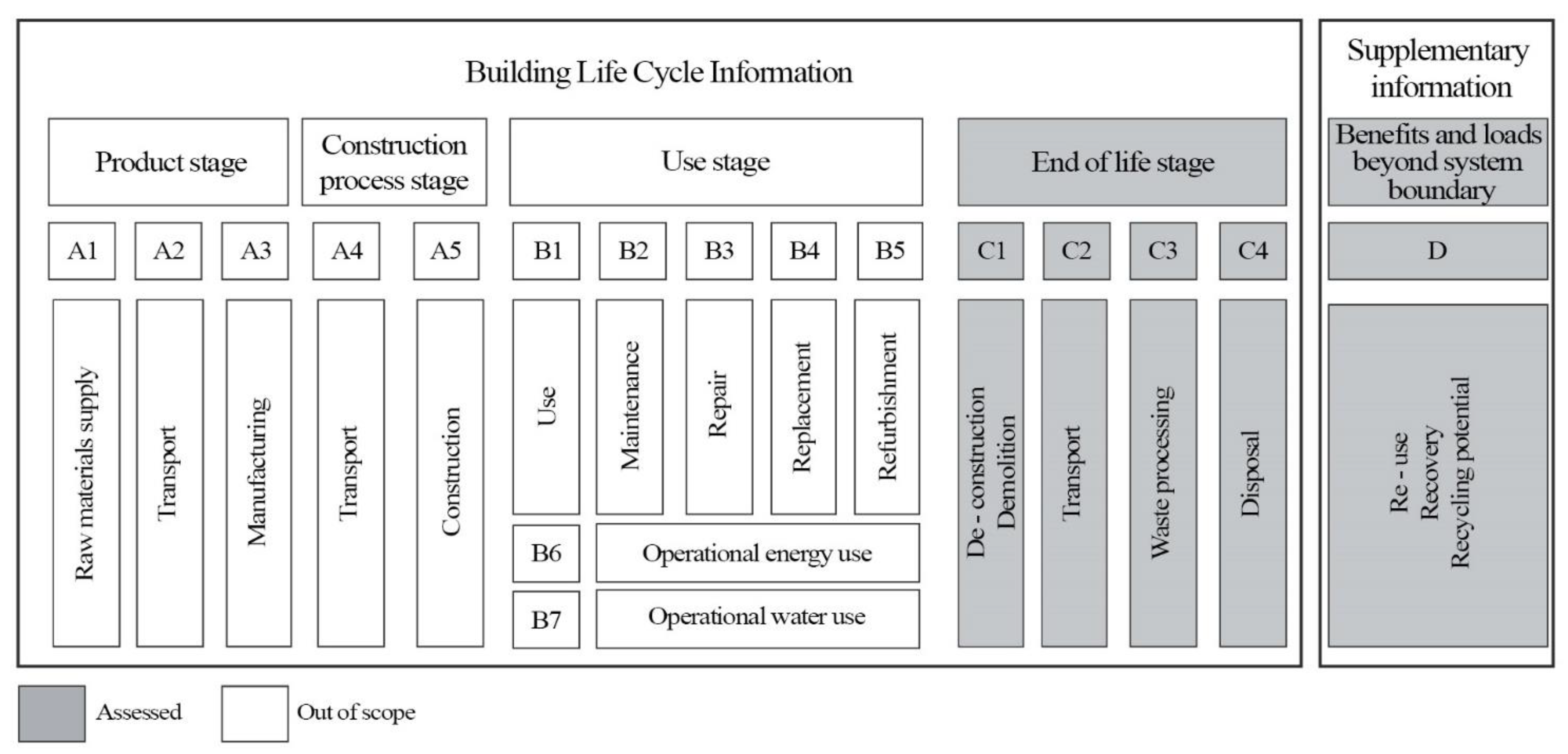
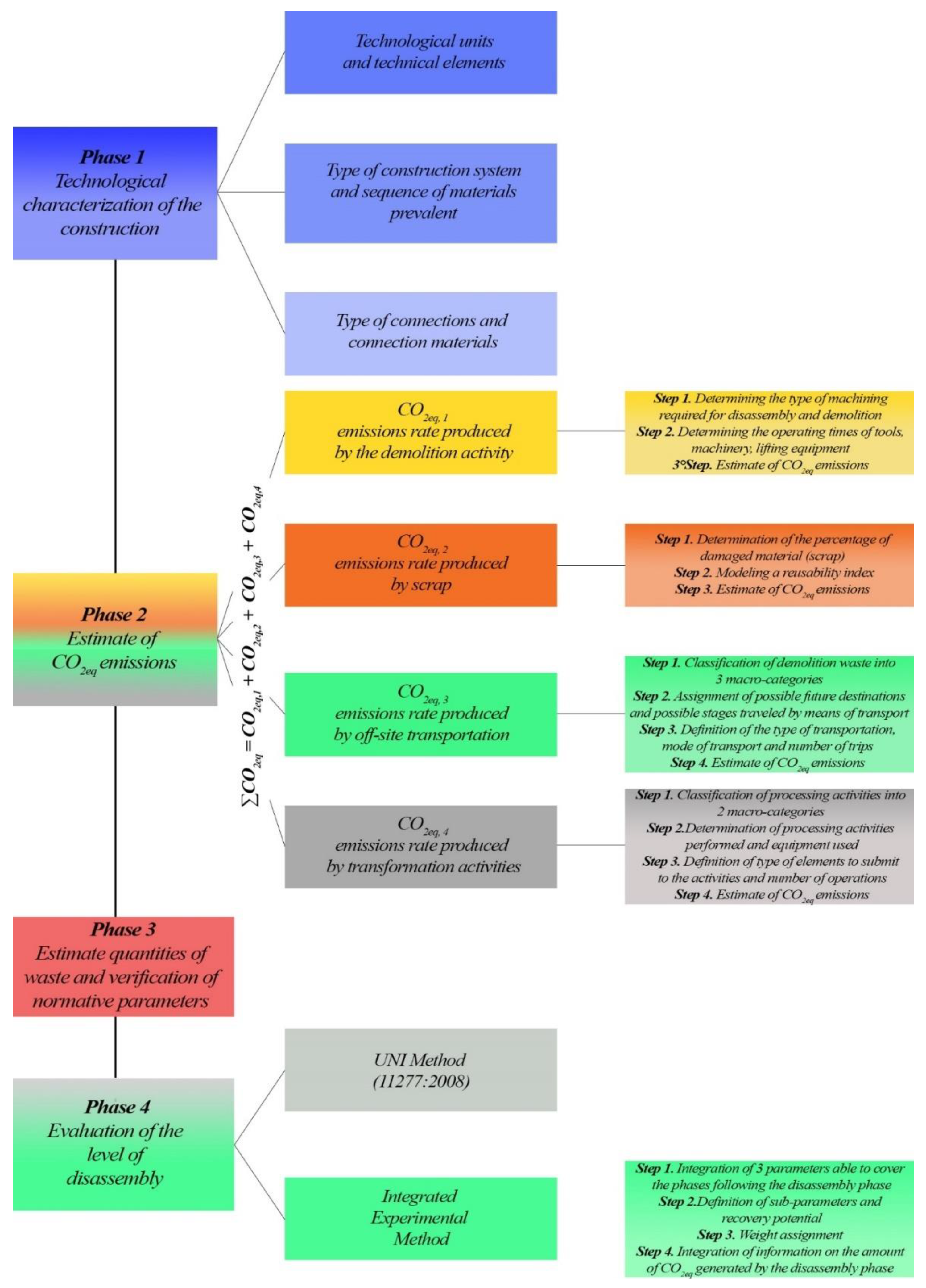
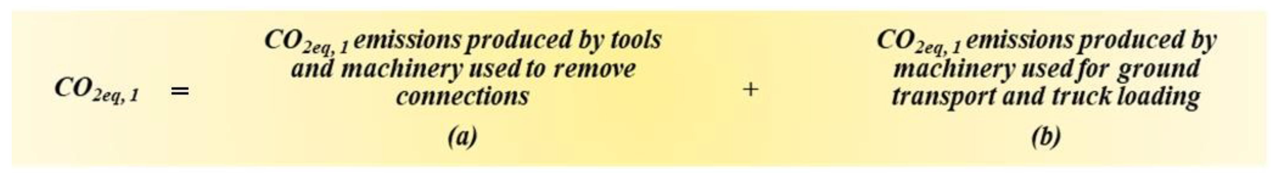
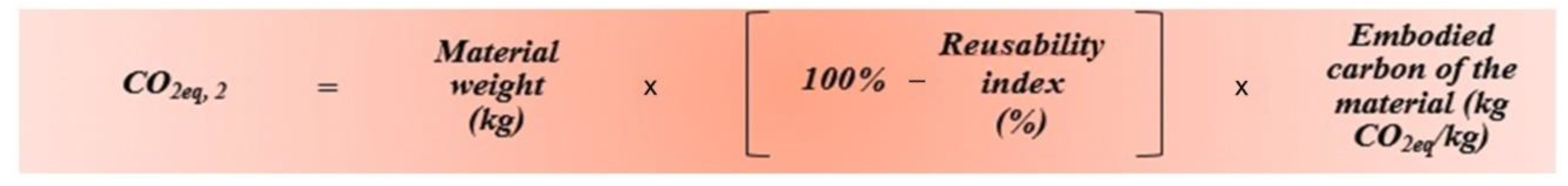
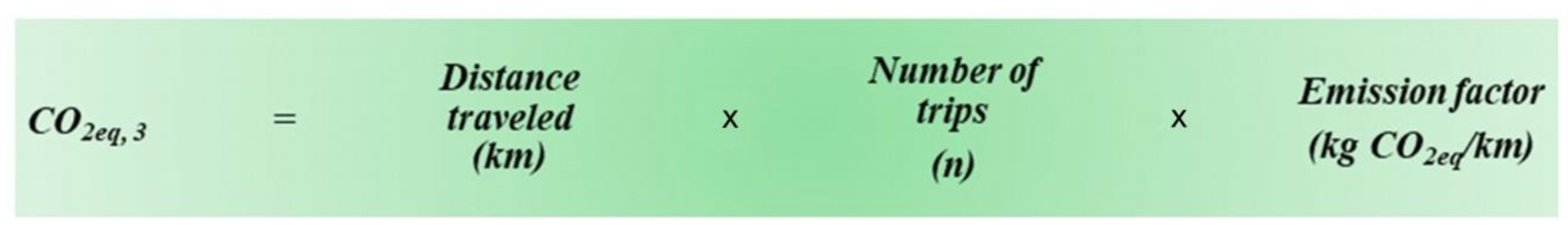
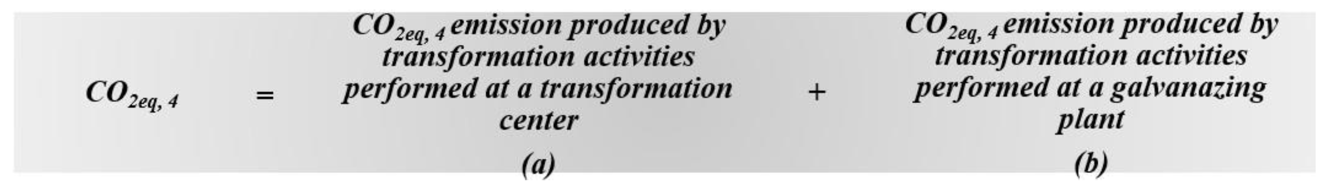
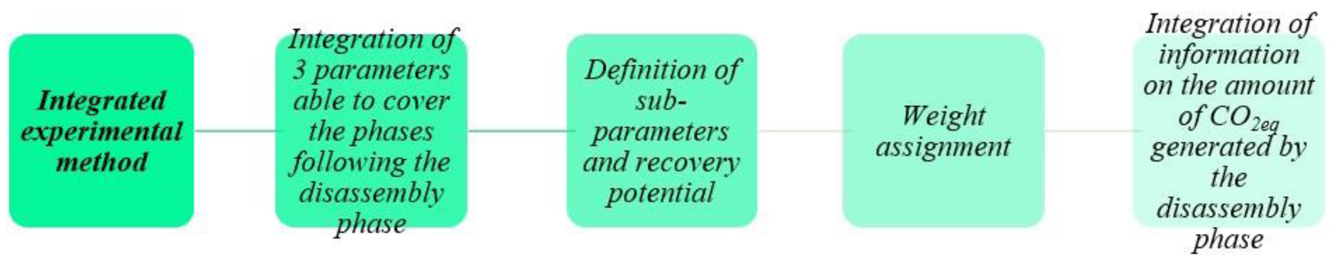
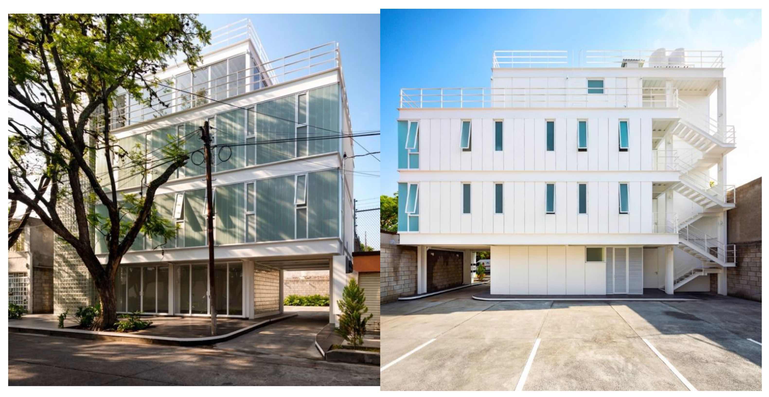
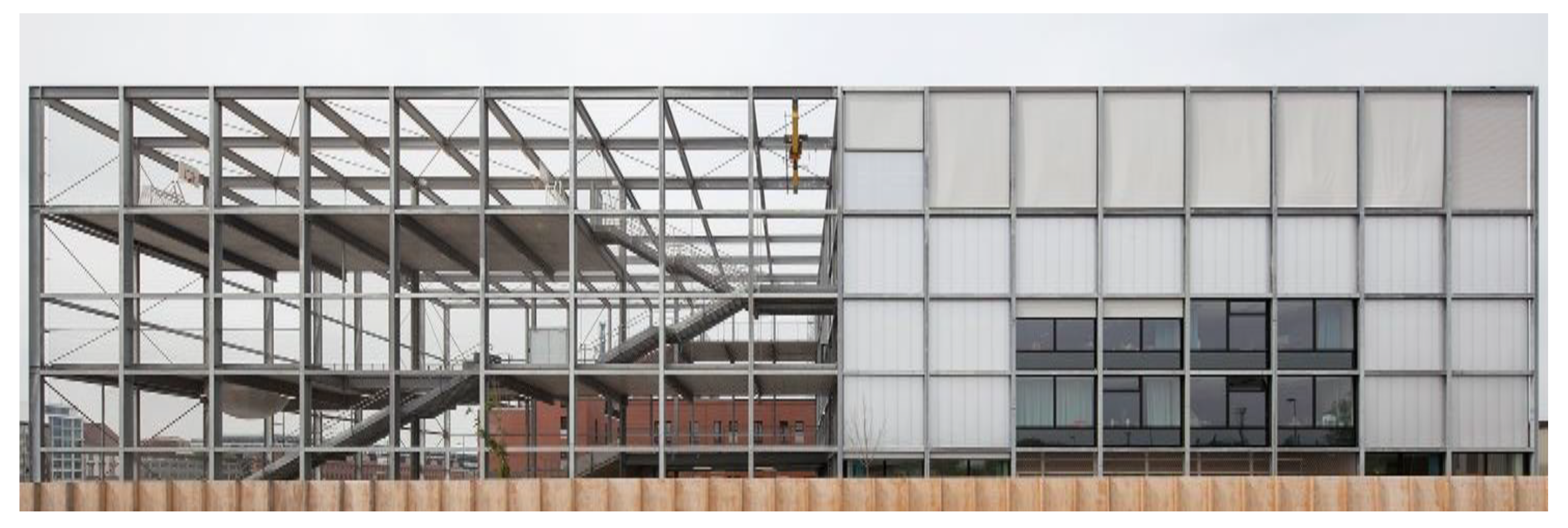
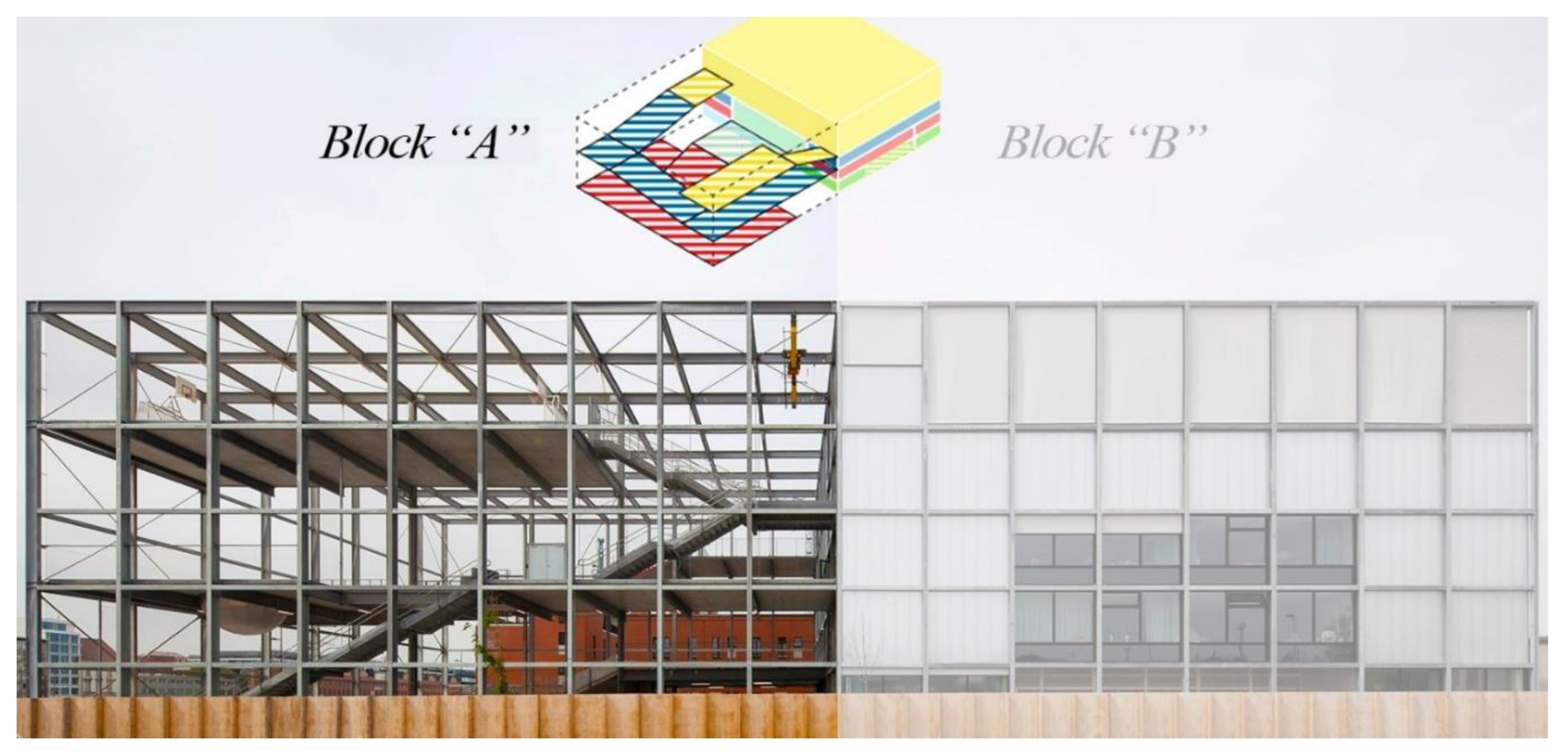
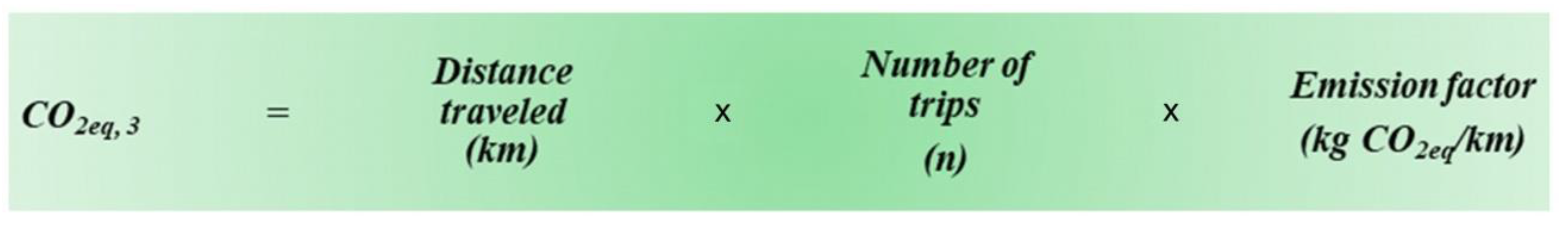
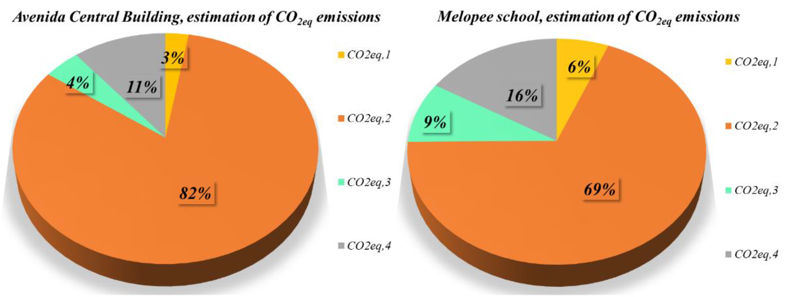
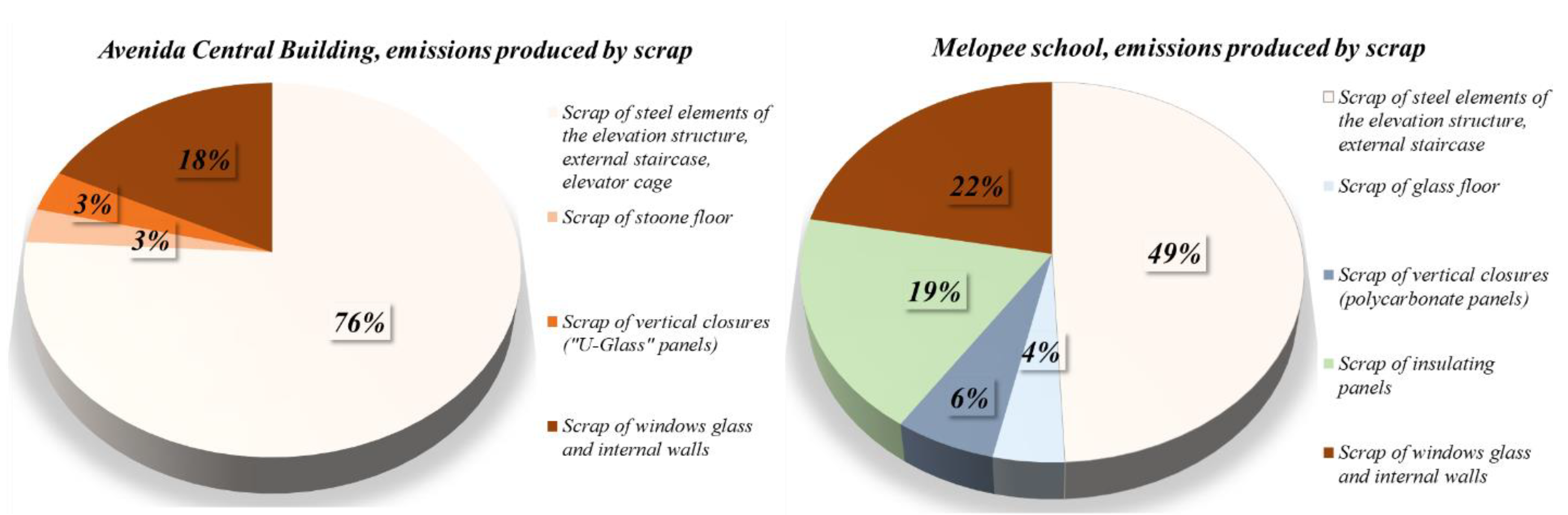
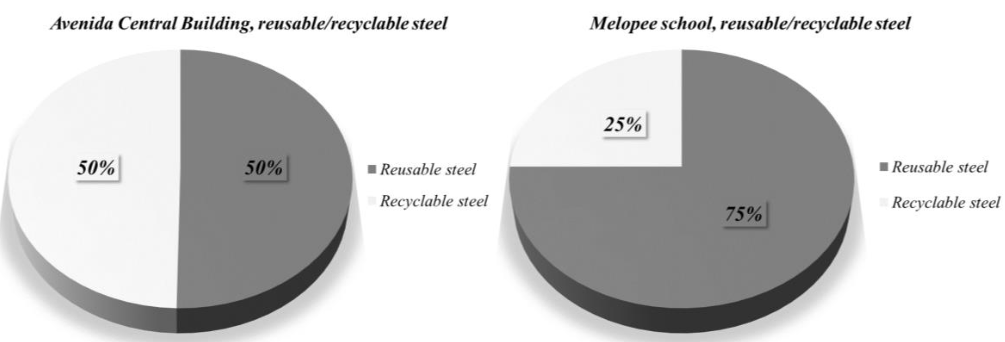
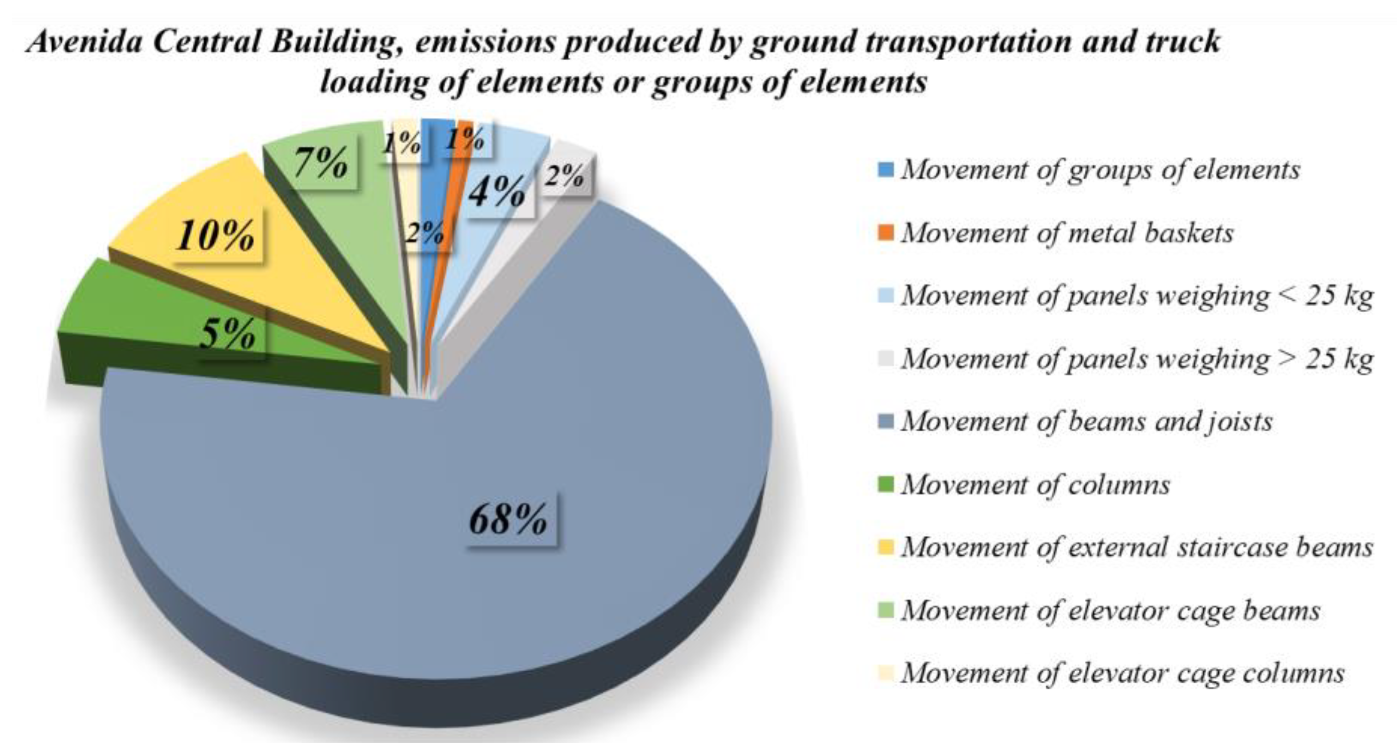
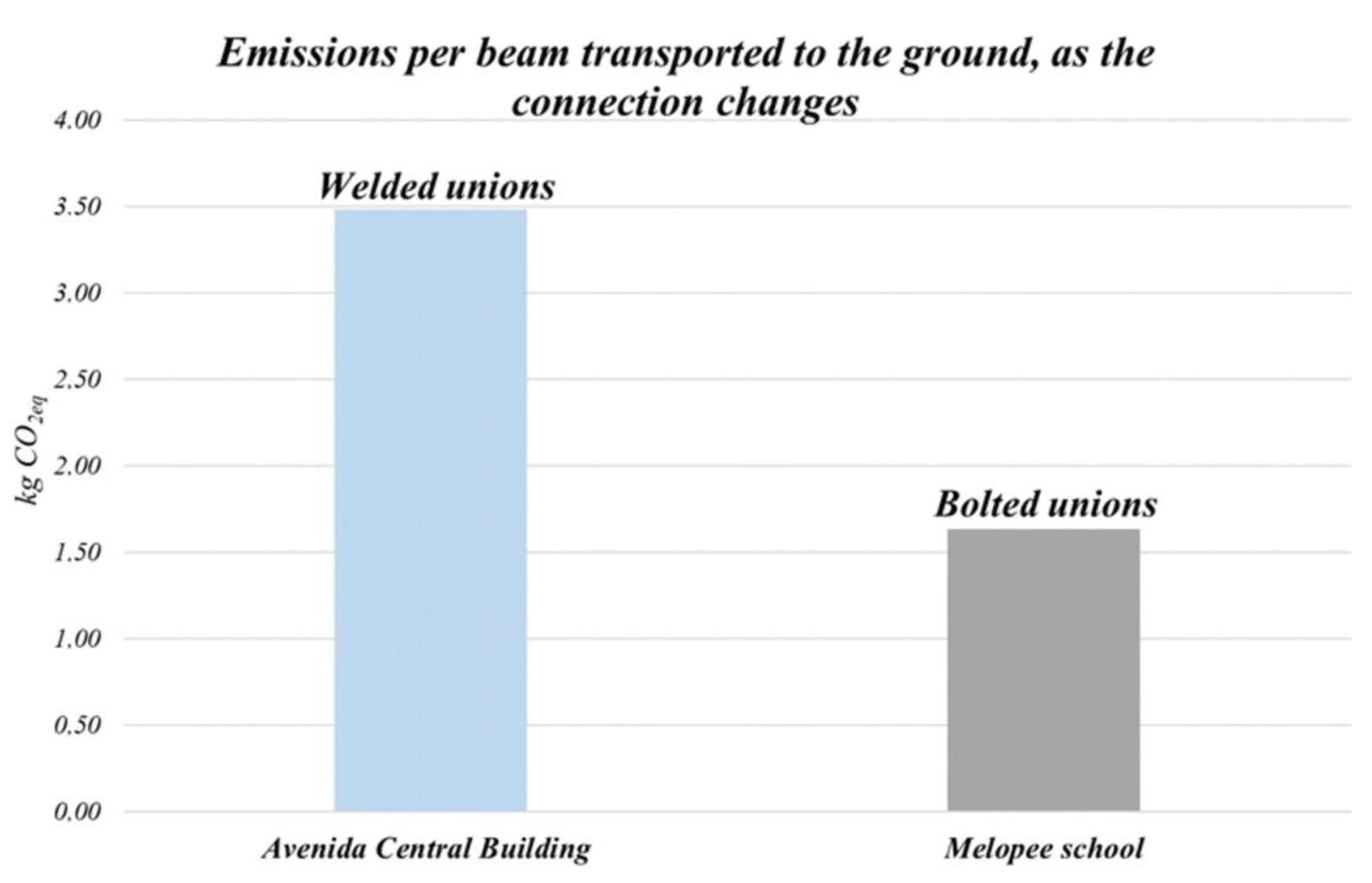
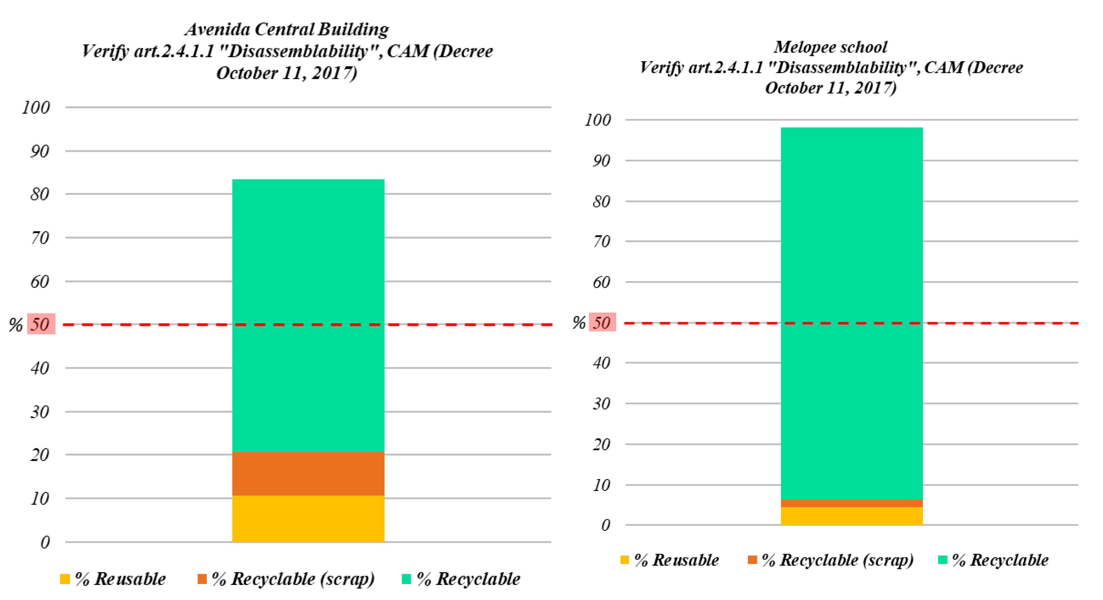
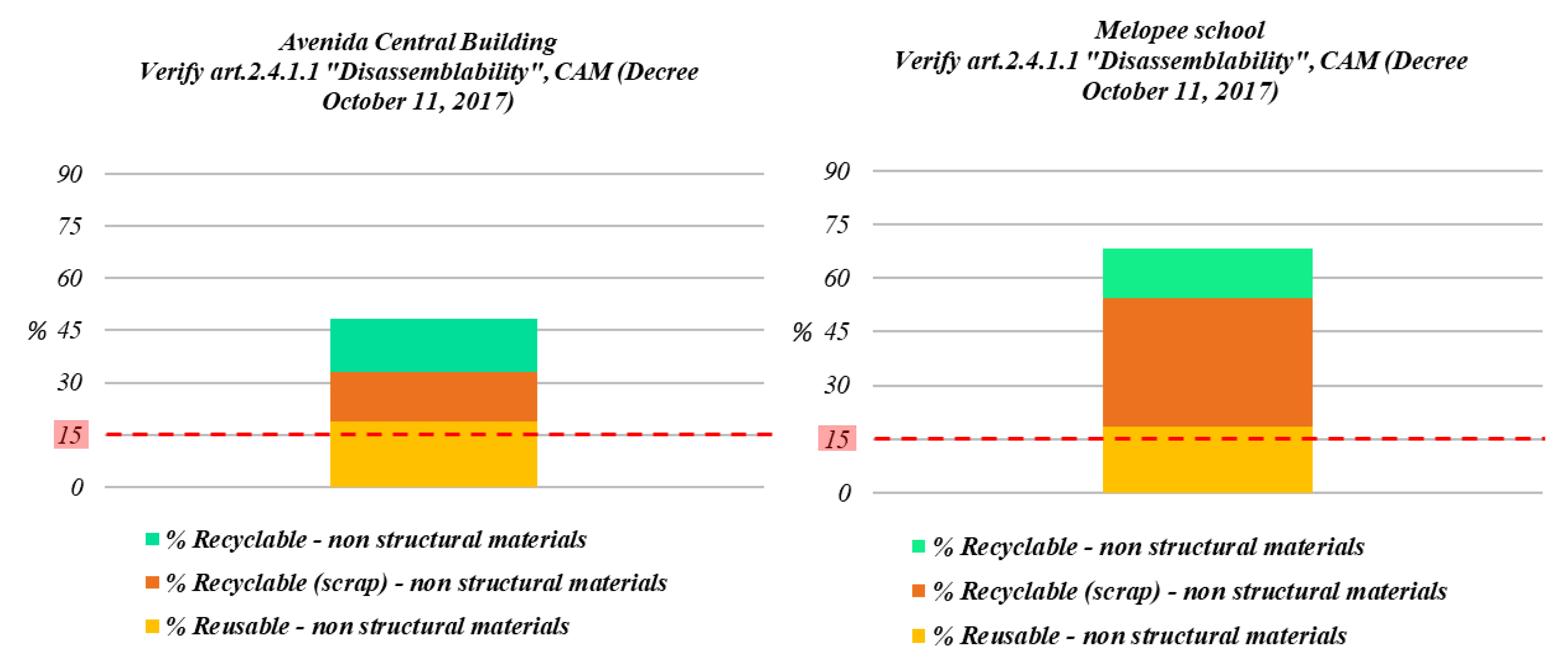
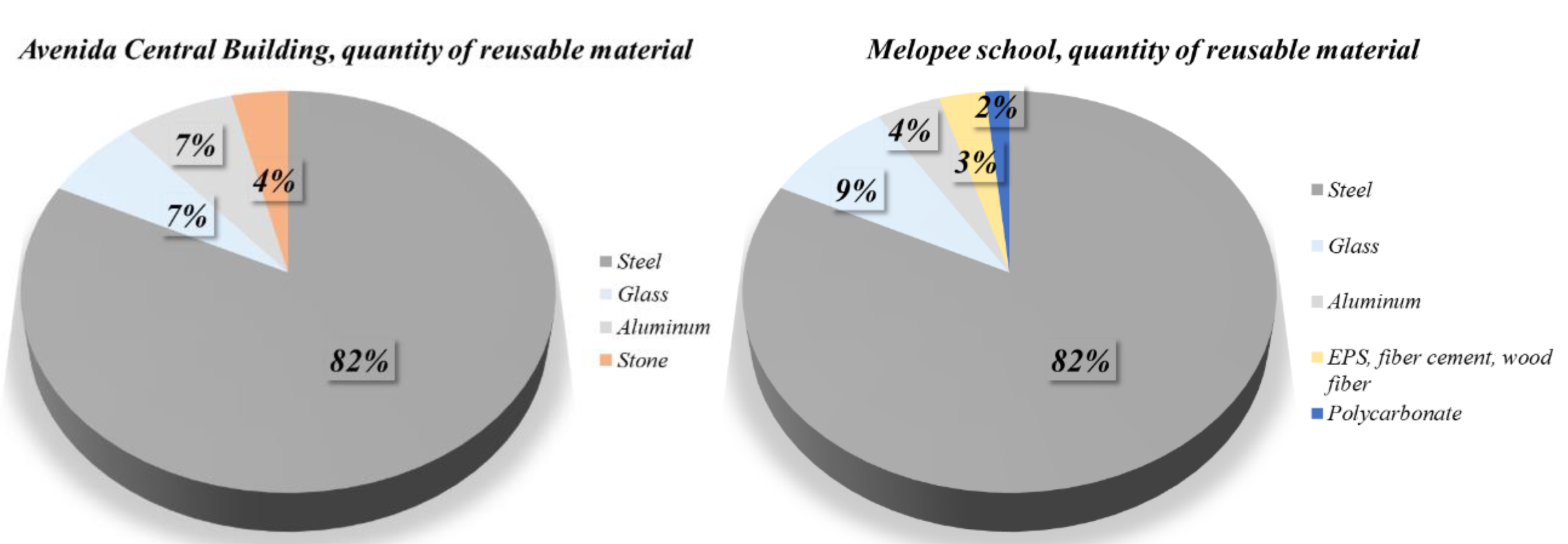
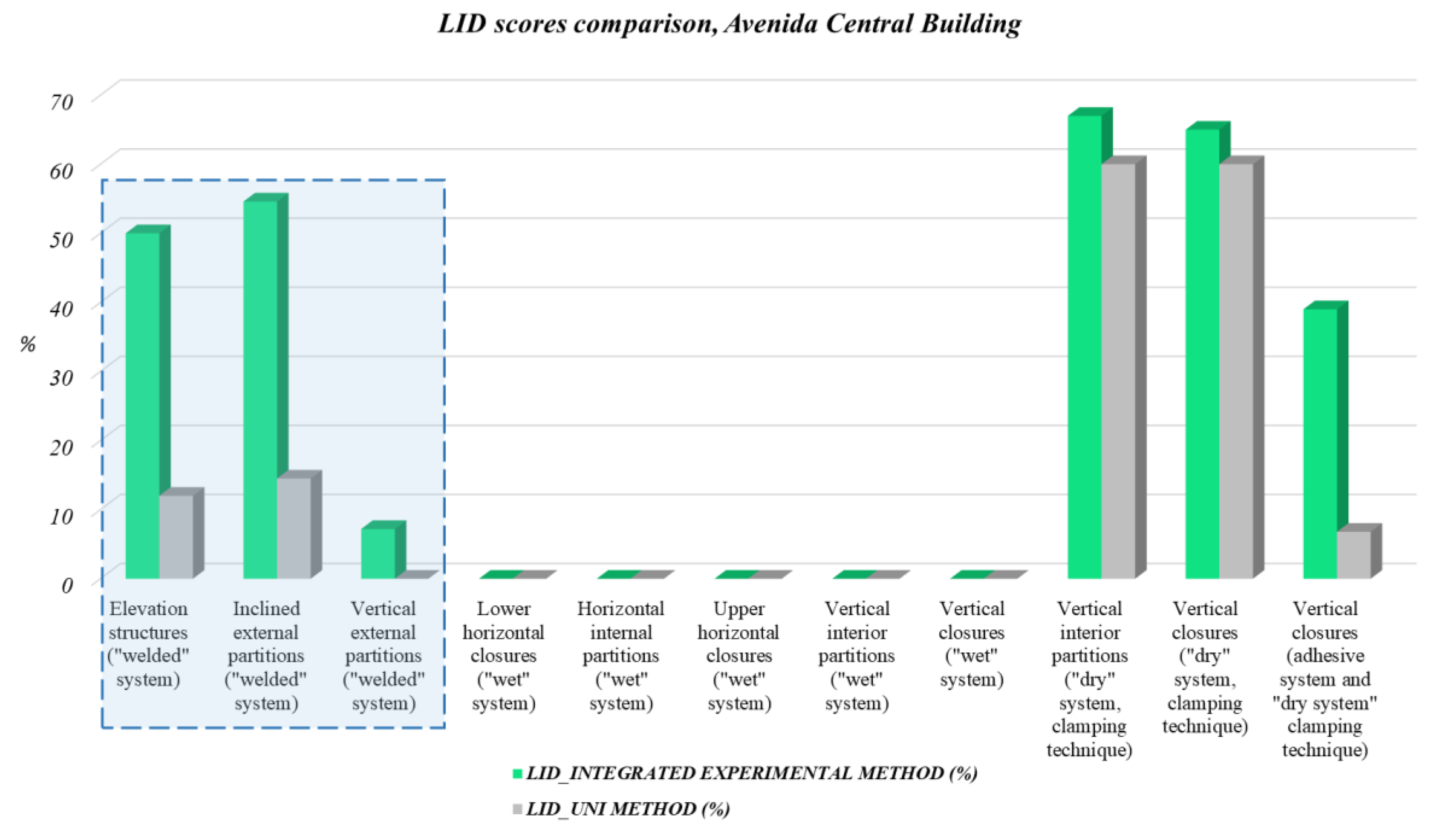
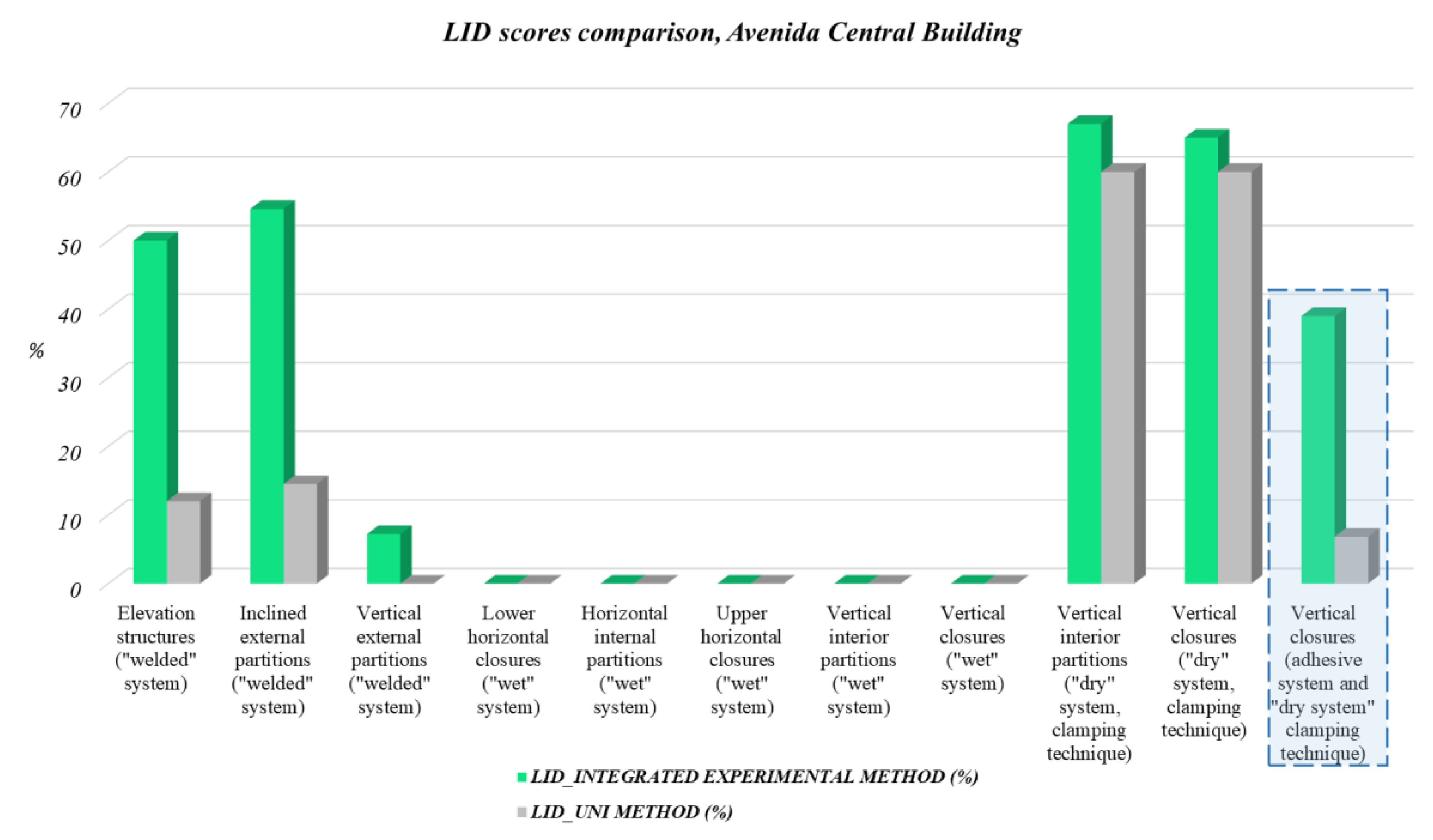
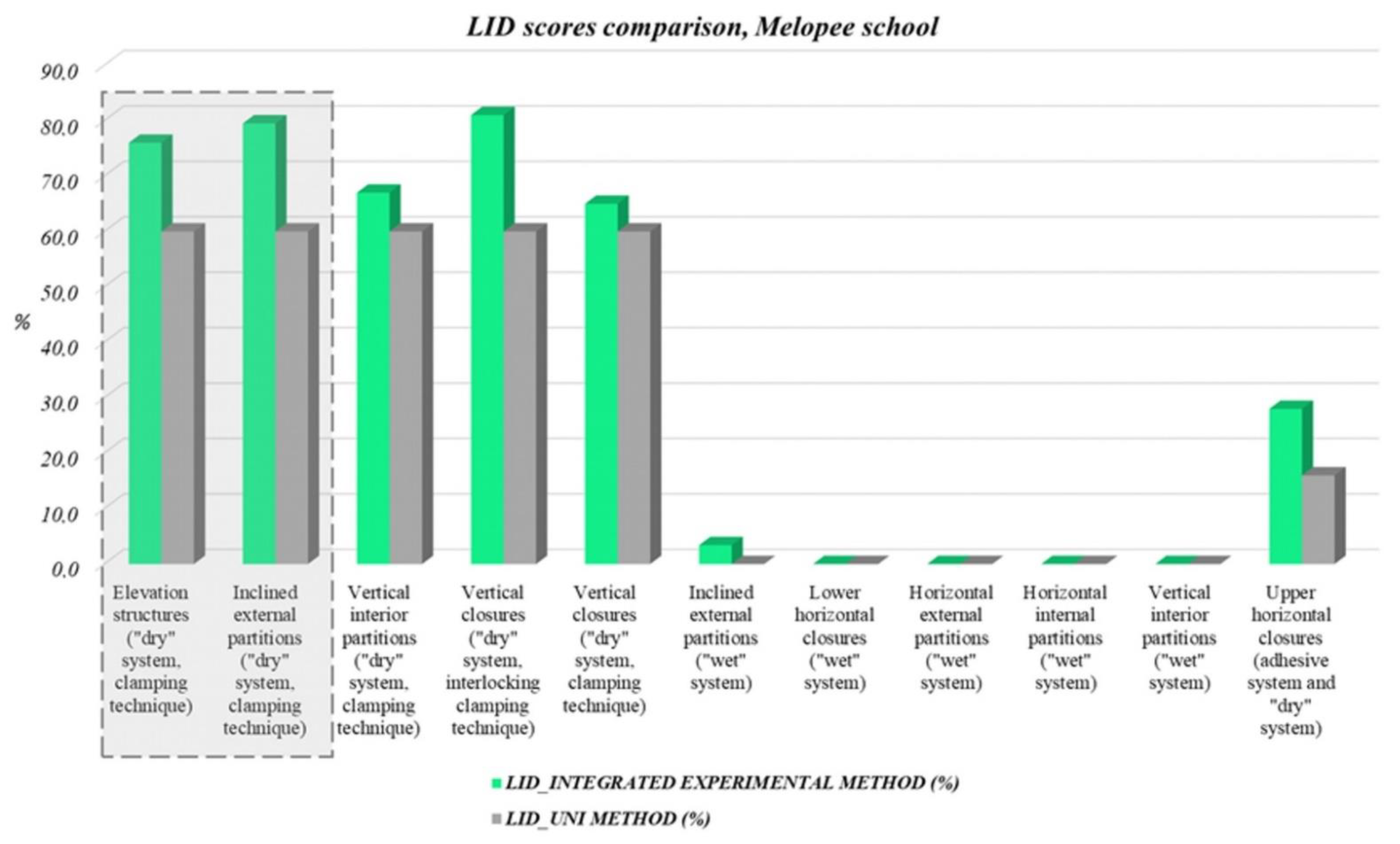
Table 1.
Tools and machinery used to remove connections.
| Connection Type | Tool or Machinery | Model |
|---|---|---|
| Snap joints, simple overlap | Manual disassembly | / |
| Bolts (M5-M12) | Impact wrenches | HILTI SIW 22-A |
| Bolts (M8-M16 high resistance; M12-M27) | Impact wrenches | HILTI SIW 22T-A 3/4 |
| Screws (for fixing, self-drilling, self-tapping), rivets | Drills | HILTI ST1800-A22 |
| Nails | Nail puller | / |
| Adhesive (with fusion, chemical reaction, evaporation | Manual disassembly, nail puller | / |
| Welds | Manual plasma cutting | CUTMASTER 120 |
| Hydraulic and aerial binders (large-size slabs) | Excavators with demolition hammer | Excavators TAKEUCHI [the model depends on the size of the construction]—demolition hammer BOBCAT |
| Hydraulic and aerial binders (small-size slabs) | Demolition hammers | HILTI TE 3000-AVR |
| Hydraulic and aerial binders (concrete or brick walls) | Demolition hammers | HILTI TE 700-AVR SDS MAX |
Table 2.
Overhead platforms used for the removal of overhead connections.
| Job Type/Max. Altitude | Aerial Platforms | Model |
|---|---|---|
| Indoor work Max. altitude = 5.90 m | Vertical platforms | GENIE GS 1330M E-Drive |
| Outdoor work Max. altitude, vertical = 20.00 m Max. altitude, horizontal = 11.15 m | Self-propelled platforms | GENIE Z-60/37 DC |
| Outdoor work Max. altitude, vertical = 43.15 m Max. altitude, horizontal = 21.26 m | Self-propelled platforms | GENIE ZX-135/70 DC |
Table 3.
Mode of transport and loading on lorry and/or articulated vehicle.
| Mass Range (P) and Length Range (L) | Ground Transportation and Truck Loading Methods | Lifting Equipment Model | |
|---|---|---|---|
| <25 kg, ground floor | P < 25 kg L < 1.50 m | Manual ground transportation | / |
| Loading on truck of a group of elements weighing <2000 kg placed in a metal basket hooked to a telescopic handler | JCB 535-95 | ||
| P < 25 kg L > 1.50 m | Manual ground transportation | / | |
| Loading on truck of a group of elements weighing <3500 kg placed in a metal basket hooked to a telescopic handler | JCB 535-95 | ||
| <25 kg, upper floor | P < 25 kg L < 1.50 m | Ground transportation of a group of elements weighing <2000 kg placed in a metal basket hooked to a mobile crane or tower crane | TEREX [the model depends on the size of the construction] |
| Loading on truck of a group of elements weighing <2000 kg placed in a metal basket hooked to a telescopic handler | JCB 535-95 | ||
| P < 25 kg L > 1.50 m | Ground transportation of a group of elements hooked to a mobile crane or tower crane | TEREX [the model depends on the size of the construction] | |
| Loading on truck of a group of elements weighing <3500 kg hooked to a telescopic handler | JCB 535-95 | ||
| >25 kg | 25 kg < P < 3500 kg | Ground transportation of a single element or a group of elements hooked to a mobile crane or tower crane | TEREX [the model depends on the size of the construction] |
| Loading on truck of a single element or a group of elements hooked to a telescopic handler | JCB 535-95 | ||
| P > 3500 kg | Ground transportation of a single element hooked to a mobile crane or tower crane | TEREX [the model depends on the size of the construction] | |
| Loading on truck of a single element or a group of elements hooked to a mobile crane or tower crane | JCB 535-95 |
Table 4.
Seconds needed to remove a single connection.
| Tool/Connection | Sources | Operating Times |
|---|---|---|
| Manual disassembly/Snap joints, simple overlap | Data collected in literature [19] | <0 s |
| Impact wrenches/Bolts | Viewing of videos corresponding to real cases [20] | 3 s |
| Wrench/Bolts | Viewing of videos corresponding to real cases [21] | 6 s |
| Drills/Screws, rivets | Viewing of videos corresponding to real cases [22,23] | 1.2 s |
| Nail puller/Nails | Data collected in literature | 10 < s < 40 |
| Crowbar/Adhesive | Data collected in literature | s > 60 |
| Manual plasma cutting/Welds (single cut of a beam) | Data sheet [24] | IPE, HEA: 60 s/30 cm UNP, HEB, HEM: 60 s/25 cm |
| Excavators/Demolition of 1 m3 of concrete | Data sheet [25] | It depends on the demolition hammer installed on the excavator—Range: 0.80/1.50 m3/h (min) 7.60/15.30 m3/h (max) |
| Demolition hammers/Demolition of 1 m3 of concrete | Data collected in literature [25] | (reinforced) 6.2 h/m3 (nonreinforced) 4.1 h/m3 |
| Demolition hammers/Demolition of 1 m3 of concrete or brick walls | Data collected in literature [25] | (bricks) 1.80 h/m3 (cement) 3.90 h/m3 |
Table 5.
CO2eq emissions,1 generated by tools and machinery used for the removal of connections.
| Tool or Machinery | = | Operating Times | × | Total Numbers of Movements | × | Power or Consumption | × | Emission Factor (*) | = | CO2eq Emissions |
|---|---|---|---|---|---|---|---|---|---|---|
| Impact wrenches | s | n | 0.114 kWh | 0.28 kg CO2eq/kWh | kg CO2eq | |||||
| Drills | s | n | 0.066 kWh | 0.28 kg CO2eq/kWh | kg CO2eq | |||||
| Manual plasma cutting | s | n | 15.4 kW | 0.28 kg CO2eq/kWh | kg CO2eq | |||||
| Vertical platforms | s | n | 2.04 kWh | 0.28 kg CO2eq/kWh | kg CO2eq | |||||
| Excavators | h/m3 | m3 | Depends on the size of the construction | 3.17 kg CO2eq/L | kg CO2eq | |||||
| Demolition hammers | h/m3 | m3 | 2.07 kW (concrete) 1.3 kW (bricks) | 0.28 kg CO2eq/kWh | kg CO2eq | |||||
* Emission factor: 0.28 kg CO2eq/kWh—Source: ISPRA [26].
Table 6.
CO2eq,1 emissions from machinery used for ground transportation and loading onto trucks.
| Machinery | = | Operating Times | × | Total Numbers of Movements | × | Power or Consumption | × | Emission Factor (**) | = | CO2eq Emissions |
|---|---|---|---|---|---|---|---|---|---|---|
| Mobile crane | s | n | Depends on the size of the construction | 3.17 kg CO2eq/L | kg CO2eq | |||||
| Telescopic handler | s | n | 5.1 L/h | 3.17 kg CO2eq/L | kg CO2eq | |||||
| Vertical platform | s | n | 18.72 kWh | 0.28 kg CO2eq/kWh | kg CO2eq | |||||
** Emission factor: 3.17 kg CO2eq/L—Source: GHG information for transport services [27].
Table 7.
Reusability index: indicators, subindicators, weights and potential for recovery.
| 0–20% | 40% | 60% | 80% | 100% | |
|---|---|---|---|---|---|
| Disassembly damageP1 = 0.50 | “Wet” system Hydraulic and aerial binders “Adhesive” system Adhesive | “Welded” system Welds | “Dry” system, clamping technique Nails, rivets | “Dry” system, clamping technique Hard to access bolts, screws | “Dry” system, clamping and interlocking technique Bolts, snap joints, simple overlap |
| Handling P2 = 0.25 | Fragile elements | Mobile crane Elements length greater than 12.00 m | Mobile crane Elements length less than 12.00 m | Lift equipment (telescopic handler, metal baskets) | Manual |
| Modification P3 = 0.25 | Complete regeneration or nonreusability | Removal of welded parts (plates) or imperfections generated by the plasma cutting process | Removal of perforated parts caused by bolted or screwed connections | Removal of surface imperfections, parts damaged during disassembly or transport | Cleaning and refurbishment of the corrosion protection system |
Table 8.
CO2eq,4 emissions, generated by processing activities at a processing plant and CO2eq,4 emissions, generated by processing activities at a galvanizing plant.
Table 8.
CO2eq,4 emissions, generated by processing activities at a processing plant and CO2eq,4 emissions, generated by processing activities at a galvanizing plant.
| Transformation Activities | = | Operating Times | × | Element Size | × | Machinery Power | × | Emission Factor (*) | = | CO2eq Emissions |
|---|---|---|---|---|---|---|---|---|---|---|
| Cutting with automatic band saw | m/s | m | 15 kW | 0.28 kg CO2eq/kWh | kg CO2eq | |||||
| Hot-dip galvanizing process | / | kg | / | 0.259 kg CO2eq/kg | kg CO2eq | |||||
* Emission factor: 0.259 kg CO2eq/kg—Source: American Galvanizers Association [34].
Table 9.
Classification of the level of disassembly (LID), UNI 11277:2008.
| Construction System | Installation Technology | LID |
|---|---|---|
| “Wet” system | Hydraulic and aerial binders | 0 |
| “Adhesive” system | Adhesive (with fusion, chemical reaction, evaporation) | 0 |
| “Welded” system | Welds | 0 |
| “Dry” system, clamping technique | Nails, bolts, screws and rivets | 3 |
| “Dry” system, interlocking technique | Snap joints | 3 |
| “Dry” system, juxtaposition technique | Simple overlap | 5 |
Table 10.
CO2eq,1 emissions rate from demolition activity.
| CO2eq Emissions Rate Produced by Removal of Connections | t CO2eq | CO2eq Emissions Rate Produced by Removal of Connections | t CO2eq |
|---|---|---|---|
| Use of cordless tool to remove bolts, screws | +0.0001 | Use of cordless tool to remove bolts, screws | +0.001 |
| Use of power tools to remove welds | +0.028 | Use of power tools for demolition of concrete walls or slabs | +1.387 |
| Use of power tools for demolition of concrete walls or slabs | +0.054 | Use of excavators for the demolition of partitions and horizontal closures | +15.069 |
| Use of excavators for the demolition of slabs | +0.526 | =16.456 | |
| =0.607 | |||
| CO2eq emissions rate produced by ground transportation and truck loading | t CO2eq | CO2eq emissions rate produced by ground transportation and truck loading | t CO2eq |
| Movement of groups of elements | +0.016 | Movement of groups of elements | +0.081 |
| Movement of metal baskets | +0.007 | Movement of metal baskets | +0.009 |
| Movement of panels weighing < 25 kg | +0.034 | Movement of panels weighing > 25 kg | +0.673 |
| Movement of panels weighing > 25 kg | +0.020 | Movement of beams and joists | +1.759 |
| Movement of beams and joists | +0.590 | Movement of columns | +0.420 |
| Movement of columns | +0.046 | Movement of external staircase beams | +0.031 |
| Movement of external staircase beams | +0.084 | =2.970 | |
| Movement of elevator cage beams | +0.047 | ||
| Movement of elevator cage columns | +0.012 | ||
| =0.854 |
Table 11.
CO2eq,2 emissions rate from scrap resulting from demolition operations.
| Avenida Central Building | Melopee School | ||
|---|---|---|---|
| CO2eq Emissions Rate Produced by Scrap | t CO2eq | CO2eq Emissions Rate Produced by Scrap | t CO2eq |
| Scrap of the elements of the elevation structure (beams, columns) | +31.655 | Scrap of the elements of the elevation structure (beams, columns) | +94.480 |
| Scrap of the elements of the external staircase (beams, columns) | +0.928 | Scrap of the elements of the external staircase (beams, columns) | +2.410 |
| Scrap of the elements of the elevator cage (beams, columns) | +1.459 | Scrap of glass floor | +9.070 |
| Scrap of stone floor | +1.316 | Scrap of the elements of the vertical closures (polycarbonate panels) | +9.868 |
| Scrap of the elements of the vertical closures (“U-glass” panels) | +1.230 | Scrap of metal framing | +2.950 |
| Scrap of metal framing | +0.344 | Scrap of glass of the windows and internal walls | +12.139 |
| Scrap of glass of the windows and internal walls | +1.027 | Scrap of metal framing of the windows and internal walls | +35.393 |
| Scrap of metal framing of the windows and internal walls | +6.908 | Scrap of wood fibre panels | +17.470 |
| =44.866 | Scrap of concrete fibre panels | +19.660 | |
| Scrap of EPS | +3.120 | ||
| Scrap of corrugated steel sheets | +9.591 | ||
| =216.151 | |||
Table 12.
CO2eq,3 emissions rate from off-site transport.
| CO2eq Emissions Rate Produced by Off-Site Transportation for Recycling | t CO2eq | CO2eq Emissions Rate Produced by Off-Site Transportation for Recycling | t CO2eq |
|---|---|---|---|
| Transportation of bricks | +0.203 | Transportation of bricks | +0.840 |
| Transportation of plaster | +0.135 | Transportation of cement and concrete | +17.430 |
| Transportation of cement, concrete, and corrugated steel sheets | +0.811 | =18.270 | |
| =1.284 | |||
| CO2eq emissions rate produced by off-site transportation for disposal | t CO2eq | CO2eq emissions rate produced by off-site transportation for disposal | t CO2eq |
| Transportation of waterproofing membrane | +0.029 | Transportation of waterproofing membrane | +0.068 |
| Transportation of glass brick | +0.135 | Transportation of PUR panels | +3.570 |
| =0.164 | Transportation of rock wool panels | +0.525 | |
| Transportation of EPS panels | +1.680 | ||
| =5.843 |
Table 13.
Melopee school—CO2eq,4 emissions rate from processing activity.
| Avenida Central Building | Melopee School | ||
|---|---|---|---|
| CO2eq emissions rate produced by transformation activities | = | CO2eq emissions rate produced by transformation activities | = |
| CO2eq emissions rate produced by cleaning and cutting at processing centres | + | CO2eq emissions rate produced by cleaning and cutting at processing centres | + |
| CO2eq emissions rate produced by galvanizing process | + | CO2eq emissions rate produced by galvanizing process | + |
| CO2eq emissions rate produced by cleaning and cutting at processing centres | t CO2eq | CO2eq Emissions rate produced by cleaning and cutting at processing centres | t CO2eq |
| Removal of imperfections generated by manual plasma cutting | 0.024 | Cutting of previously bolted or screwed material | 0.038 |
| =0.024 | =0.038 | ||
| CO2eq emissions rate produced by galvanizing process | t CO2eq | CO2eq emissions rate produced by galvanizing process | t CO2eq |
| Zinc production, transportation to the plant, and galvanizing process | 5.896 | Zinc production, transportation to the plant, and galvanizing process | 51.291 |
| =5.896 | =51.291 | ||
Table 14.
Quantity of reusable material, reported by technical elements.
| Avenida Central Building, Quantity of Reusable Material | t | Melopee School, Quantity of Reusable Material | t |
|---|---|---|---|
| Steel of the elevation structure (beams, joists, columns)—structural materials | +20.32 | Steel of the elevation structure (beams, joists, columns)—structural materials | +190.69 |
| Steel of the external staircase (beams)—structural materials | +0.45 | Steel of the external staircase (beams)—structural materials | +4.18 |
| Steel of the external staircase (steps, landings)—nonstructural materials | +0.27 | Steel of the external staircase (steps, landings)—nonstructural materials | +1.87 |
| Steel of the external case (joists, columns)—structural materials | +1.20 | Polycarbonate of the vertical closure panels—nonstructural materials | +3.99 |
| Glass of the vertical closure panels—nonstructural materials | +0.46 | Aluminium of the metal frame of polycarbonate panels—nonstructural materials | +1.01 |
| Aluminium of the metal frame of glass panels—nonstructural materials | +0.12 | Glass of the windows and interior walls—nonstructural materials | +15.66 |
| Glass of the windows and interior walls—nonstructural materials | +1.32 | Aluminium of the windows and interior walls—nonstructural materials | +9.62 |
| Aluminium of the windows and interior walls—nonstructural materials | +1.88 | Glass of the external flooring—nonstructural materials | +6.30 |
| Stone of the external flooring—nonstructural materials | +1.01 | Fibre cement of the roof panels—nonstructural materials | +5.27 |
| =27.04 | Wood fibre of the roof panels—nonstructural materials | +1.87 | |
| EPS of the roof panels—nonstructural materials | +0.59 | ||
| Steel of corrugated sheets of the roof—structural materials | +9.28 | ||
| =250.33 |
Table 15.
Amount of recyclable material (scrap), reported by technical elements.
| Avenida Central Building, Quantity of Recyclable Material (scrap) | t | Melopee School, Quantity of Recyclable Material (Scrap) | t |
|---|---|---|---|
| Steel of the elevation structure (beams, joists, columns)—structural materials | +20.42 | Steel of the elevation structure (beams, joists, columns)—structural materials | +60.95 |
| Steel of the external staircase (beams)—structural materials | +0.55 | Steel of the external staircase (beams)—structural materials | +1.20 |
| Steel of the external staircase (steps, landings)—nonstructural materials | +0.05 | Steel of the external staircase (steps, landings)—nonstructural materials | +0.35 |
| Steel of the external case (joists, columns)—structural materials | +0.94 | Polycarbonate of the vertical closure panels—nonstructural materials | +0.70 |
| Glass of the vertical closure panels—nonstructural materials | +0.85 | Aluminium of the metal frame of polycarbonate panels—nonstructural materials | +0.43 |
| Aluminium of the metal frame of glass panels—nonstructural materials | +0.05 | Glass of the windows and interior walls—nonstructural materials | +8.43 |
| Glass of the windows and interior walls—nonstructural materials | +0.71 | Aluminium of the windows and interior walls—nonstructural materials | +5.18 |
| Aluminium of the windows and interior walls—nonstructural materials | +1.01 | Glass of the external flooring—nonstructural materials | +6.30 |
| Stone of the external flooring—nonstructural materials | +1.01 | Fibre cement of the roof panels—nonstructural materials | +12.29 |
| =25.60 | Wood fibre of the roof panels—nonstructural materials | +4.37 | |
| EPS of the roof panels—nonstructural materials | +0.39 | ||
| Steel of corrugated sheets of the roof—structural materials | +6.19 | ||
| = 106.79 |
Table 16.
Quantity of material to be disposed of, reported by technical elements.
| Avenida Central Building, Quantity of Material to be Disposed | t | Melopee School, Quantity of Material to be Disposed | t |
|---|---|---|---|
| Waterproofing membranes of the roof—nonstructural materials | +0.24 | Waterproofing membranes of the roof—nonstructural materials | +5.85 |
| Glass brick of the external cage—nonstructural materials | +15.85 | PUR of the roof panels—nonstructural materials | +16.38 |
| =16.09 | PUR of the slabs—nonstructural materials | +12.95 | |
| PUR of interior walls—nonstructural materials | +8.80 | ||
| Stone wool of the slabs—nonstructural materials | +3.38 | ||
| EPS of the slabs—nonstructural materials | +11.70 | ||
| =59.06 |
Table 17.
Disassembly level assessment. Integrated experimental method.
| LID, Integrated Experimental Method | ||||||
|---|---|---|---|---|---|---|
| Technological unit | Technical Elements | Materials | Parameters | LID, Materials (%) | LID, Technological Unit (%) | |
| Melopee | Elevation structures | Vertical elevation structures | Steel columns | Bolts (100%)—Ground transportation with crane, l > 12 m (40%)—Removal of perforated parts (60%) | 76 | 76 |
| Horizontal elevation structures | Steel beams | Bolts (100%), Ground transportation with crane (40/60%), Removal of perforated parts (60%) | 78 | |||
| Avenida | Elevation structures | Vertical elevation structures | Steel columns | Bolts (100%)—Ground transportation with crane, l >12 m (40%)—Removal of welded parts (40%) | 75 | 50 |
| Horizontal elevation structures | Steel beams | Welds (40%), Ground transportation with crane (40/60%), Removal of welded parts (40%) | 45 | |||
Table 18.
Disassembly level assessment. UNI method (11277:2008).
| LID, UNI Method | ||||||
|---|---|---|---|---|---|---|
| Technological Unit | Technical Elements | Materials | Parameters | LID, Materials (0/5) | LID, Technological Unit (0/5) | |
| Melopee | Elevation structures | Vertical elevation structures | Steel columns | Bolts | 3 | 3 |
| Horizontal elevation structures | Steel beams | Bolts | 3 | |||
| Avenida | Elevation structures | Vertical elevation structures | Steel columns | Bolts | 3 | 0.60 |
| Horizontal elevation structures | Steel beams | Welds | 0 | |||
Publisher’s Note: MDPI stays neutral with regard to jurisdictional claims in published maps and institutional affiliations. |
© 2021 by the authors. Licensee MDPI, Basel, Switzerland. This article is an open access article distributed under the terms and conditions of the Creative Commons Attribution (CC BY) license (https://creativecommons.org/licenses/by/4.0/).
Share and Cite
MDPI and ACS Style
Melella, R.; Di Ruocco, G.; Sorvillo, A. Circular Construction Process: Method for Developing a Selective, Low CO2eq Disassembly and Demolition Plan. Sustainability 2021, 13, 8815. https://0-doi-org.brum.beds.ac.uk/10.3390/su13168815
AMA Style
Melella R, Di Ruocco G, Sorvillo A. Circular Construction Process: Method for Developing a Selective, Low CO2eq Disassembly and Demolition Plan. Sustainability. 2021; 13(16):8815. https://0-doi-org.brum.beds.ac.uk/10.3390/su13168815
Chicago/Turabian StyleMelella, Roberta, Giacomo Di Ruocco, and Alfonso Sorvillo. 2021. "Circular Construction Process: Method for Developing a Selective, Low CO2eq Disassembly and Demolition Plan" Sustainability 13, no. 16: 8815. https://0-doi-org.brum.beds.ac.uk/10.3390/su13168815
Note that from the first issue of 2016, this journal uses article numbers instead of page numbers. See further details here.