Using Recycled Material from the Paper Industry as a Backfill Material for Retaining Walls near Railway Lines


Department of Geotechnics and Traffic Infrastructure, Slovenian Building and Civil Engineering Institute, ZAG, 1000 Ljubljana, Slovenia
*
Author to whom correspondence should be addressed.
Sustainability 2021, 13(2), 979; https://0-doi-org.brum.beds.ac.uk/10.3390/su13020979
Submission received: 2 December 2020
/
Revised: 6 January 2021
/
Accepted: 14 January 2021
/
Published: 19 January 2021
(This article belongs to the Special Issue Technology and Management for Sustainable Buildings and Infrastructures)
Abstract
:The construction industry uses a large amount of natural virgin material for different geotechnical structures. In Europe alone, 11 million tonnes of solid waste is generated per year as a result of the production of almost 100 million tonnes of paper. The objective of this research is to develop a new geotechnical composite from residues of the deinking paper industry and to present its practical application, e.g., as a backfill material behind a retaining structure. After different mixtures were tested in a laboratory, the technology was validated by building a pilot retaining wall structure in a landslide region near a railway line. It was confirmed that a composite with 30% deinking sludge and 70% deinking sludge ash had a high enough strength but experienced some deformations before failure. Special attention was paid to the impact of transport, which, due to the time lag between the mixing and installation of the composite, significantly reduced its strength. The pilot retaining wall structure promotes the use of recycled materials with a sustainable design, while adhering to government-mandated measures.
1. Introduction
According to information published by the European Aggregate Association, the demand for European aggregates is 3 billion tonnes annually [1]. About half of natural (virgin) material is consumed by the construction industry, which also generates a large amount of waste material [2]. Undoubtedly, virgin material can partially be replaced by other materials, such as recycled industrial material, including material made from paper industry waste. This recycled waste can be substituted for virgin aggregates that are used in various applications in the building sector in huge quantities, especially for roads and earthworks [3]. Of course, the mechanical and environment criteria for recycled materials according to the national legislation must be satisfied.
Globally, 420 million tonnes of paper and paperboard are produced annually [4], and production is growing. The production processes result in significant waste generation; 11 million tonnes of solid waste are generated per year in Europe [5]. Approximately 70% of this waste is from paper recycling, for example, deinking sludge [6]. According to the Integrated Pollution Prevention and Control Directive 1996/61/CE [7], the paper industry is required to minimize the amount of waste and develop more sustainable technologies for waste treatment. There are also EU waste management legislative measures and policies [8] implementing a waste hierarchy, with landfilling being the least desirable option and recycling the most, supported by increased taxes for landfilling. Recycled paper residues are a potential material that could be substituted for virgin raw materials from a technical and economical point of view [9,10].
Examples of pulp and paper industry residue implementation have been presented by other authors [11,12,13,14], but in general, most paper industry waste is burned in power plant boilers or landfilled. The production process with different fillers, pigments, and coagulates influences the type of paper ash. Also, the technology and temperature in the boilers have an effect [15,16].
If paper sludge ash were to be used only as a binder in the construction industry, some problems due to the presence of lime would be observed, but it could be very useful for the stabilization of road structures or as a backfill material [17]. Different mixtures of paper ash and paper sludge have been tested on a laboratory scale. A mixture of sand, paper fly ash, paper sludge, and cement has been used in laboratory research [18]. The mixture reached a compressive strength of 0.8 MPa, which is high enough for use as a backfill material for a foundation structure, a structural fill, or a hydraulically bound layer in a road structure. If the paper sludge ash is mixed with recycled concrete aggregate (RCA), the mechanical properties are improved, especially the resistance to acid and sulfate attacks [19]. Highly plastic clay soil was stabilized with paper sludge ash [20,21,22] and the compressive strength increased enough (0.7, 1 MPa) for the mixture to be used without any other additives for a pozzolanic reaction. For mining backfill material, a mixture of paper sludge ash and sewage sludge ash [23] was prepared. Both materials were mixed and calcinated at high temperatures. In addition to paper sludge ash, paper sludge can be used. Paper sludge was used with marine-washed sand, aggregate, and Portland cement [24]. With this mixture, a compressive strength of 8 MPa was achieved. Remediation of contaminated soil by red mud was used with paper ash as a binder material [25].
Most of the research is related to laboratory tests, but some field results have also been published. A road subgrade was stabilized in a length of 250 m with a mixture of paper sludge and cement in Portugal [26]. The installed mixture achieved an unconfined compressive strength of 4.5 MPa. Paper fly ash was used for gravel road stabilization of a hydraulically bound layer [27] in Spain. The hydraulically bound layer reached an unconfined compressive strength of 5 MPa.
Paper sludge ash is also used in the cement industry as supplementary cementitious material in mortar [28,29], concrete manufacturing [30,31], and the brick industry [32].
When using ash as a building material, particular attention should be paid to the impact on the environment. Studies have demonstrated the wide applicability of ash, but it is necessary to carefully investigate the potential environmental impact and use technology that is appropriate for individual recycled materials [33,34].
Investors and designers find it difficult to decide to use recycled material in construction due to a lack of knowledge about the material, technology of installation, high cost of production, and often a negative attitude towards all new materials [1]. The objective of this research is to develop a new backfill material (composite) used behind retaining walls from the residue of paper industry production and promote the use of the recycled material with a pilot structure. Especially in mountainous regions, landslides represent a threat to roads and railways, which must be reduced by slope stabilization with different retaining walls. A new composite must have high enough unconfined compressive strength and shear properties, but at the same time has to allow elastic deformation before cracking. Until now, paper sludge ash and deinking sludge have been used in different mixtures, usually in mixtures with soil and other binders. At present, deinking sludge ash and deinking sludge are mixed together as a new composite in a precise ratio and compacted under strict conditions behind a retaining wall. This type of composite has not been tested in the laboratory so far, nor has its use been validated in field tests.
None of the studies to date have dealt with changing the strength characteristics of the material during mixing and installation. Here, the time of transport of the material from the place of mixing to installation is crucial. In the study, we found that, over time, the strength properties decrease significantly, which may be crucial for the stability of the retaining wall. The study notes that the materials in the laboratory must also be tested in terms of installation time in order to provide the designer with relevant data regarding the geomechanical characteristics of the composite.
The pilot retaining wall structure promotes the concept of a circular economy from idea to laboratory tests, installing the structure, and monitoring it over a long period of time. The new composite and the technology were tested at a construction site and then monitored over a longer period of time. This gives us information about the details of construction and proves that the structure is stable, usable, and meets all the technical and environmental standards available to investors, designers, and contractors. Pilot structures could help suppliers, investors, designers, and contractors identify the factors hampering the use of recycled materials in the construction sector as well as provide strategies that can be adopted to form an economical and sustainable product.
2. Materials and Methods
2.1. Material Used
Deinking sludge ash (DSA) and deinking sludge (DS), used in this study as raw materials, represent the main waste from recycled deinking paper pulp production at a paper industry company, VIPAP Videm Krško d.d., in Slovenia. The DSA is a combustion residue formed in a steam boiler during the incineration of DS. It consists of a mixture of bottom ash (approx. 90 wt%) and fly ash (approx. 10 wt%). VIPAP recycles around 600 tonnes of paper daily. Annually, 25,000 tonnes of DSA and 67,000 tonnes of DS are produced. According to the European Waste Catalogue (EWC), DSA is classified as 10 01 01, while DS is classified as 03 03 05 [35].
2.2. Methods
2.2.1. Testing of Raw Materials
The bulk chemical composition of the DSA and DS was determined by a Wavelength Dispersive X-ray Fluorescence (WD XRF), using a Thermo Scientific ARL PERFORM’X Spectrometer (Waltham, MA, USA). Analysis of loss on ignition (LOI) and the total chloride content of DSA was performed according to SIST EN 196-2 [36]. The physical and mechanical properties of the raw materials were tested according to the standards in Table 1.
Particle size distribution of DSA was measured by laser diffraction analysis (particles < 400 μm) using a CILAS 920 Particle Size Analyser (Cilas, Orléans, France).
2.2.2. Preliminary Laboratory Tests of Composite
In order to design a backfill material for a retaining wall structure for the stabilization of a landslide near a railway line, several mixtures consisting of different ratios of DSA and DS were tested. Among them, two mixtures (Table 2) with sufficiently good geomechanical characteristics and suitable properties for compaction and installation were tested in detail.
Geomechanical tests were performed in an accredited geomechanical laboratory, according to SIST EN ISO/IEC 17025 [37].
The components were mixed in a 20 L planetary mixer. Two kilograms were mixed for 2 min until a homogeneous mixture was obtained. Mixtures were compacted at the maximum dry density according to the SIST EN 13286-2 [38]. In order to prevent evaporation, the composites were stored and cured in a climatic chamber at 90% RH and 22 °C.
Compressive strength was tested according to SIST EN 13286-41 [39] immediately after compaction and after one, four, seven, 28, and 50 days of curing.
Freezing/thawing tests were performed according to Slovenian technical specification TSC 06.320 [40]. According to the specification, the composites were exposed to 12 cycles of freezing at −23 °C and thawing at 20 °C in a climate chamber.
The shear characteristics of the composites were tested according to the SIST EN ISO 17892-10 [41] directly after compaction and after seven days of curing. The permeability of the composite was tested in a triaxial cell, according to SIST EN ISO 17892:11 [42] under a pressure of 50 kPa.
In order to investigate the impact of the transport time to the construction site, the time delay between mixing and compacting was taken into account. The tests were performed with two different testing procedures:
- -
- The material was moistened to the maximum water content (wmax) and cured in the open air,
- -
- The material was moistened to the optimal water content (wopt) and cured in closed boxes.
After moistening and mixing, the mixtures were compacted in the following time intervals: immediately, and after 4, 8, and 24 h. After seven days, an unconfined compressive strength test was performed on each specimen.
2.2.3. Test of Pilot Structure
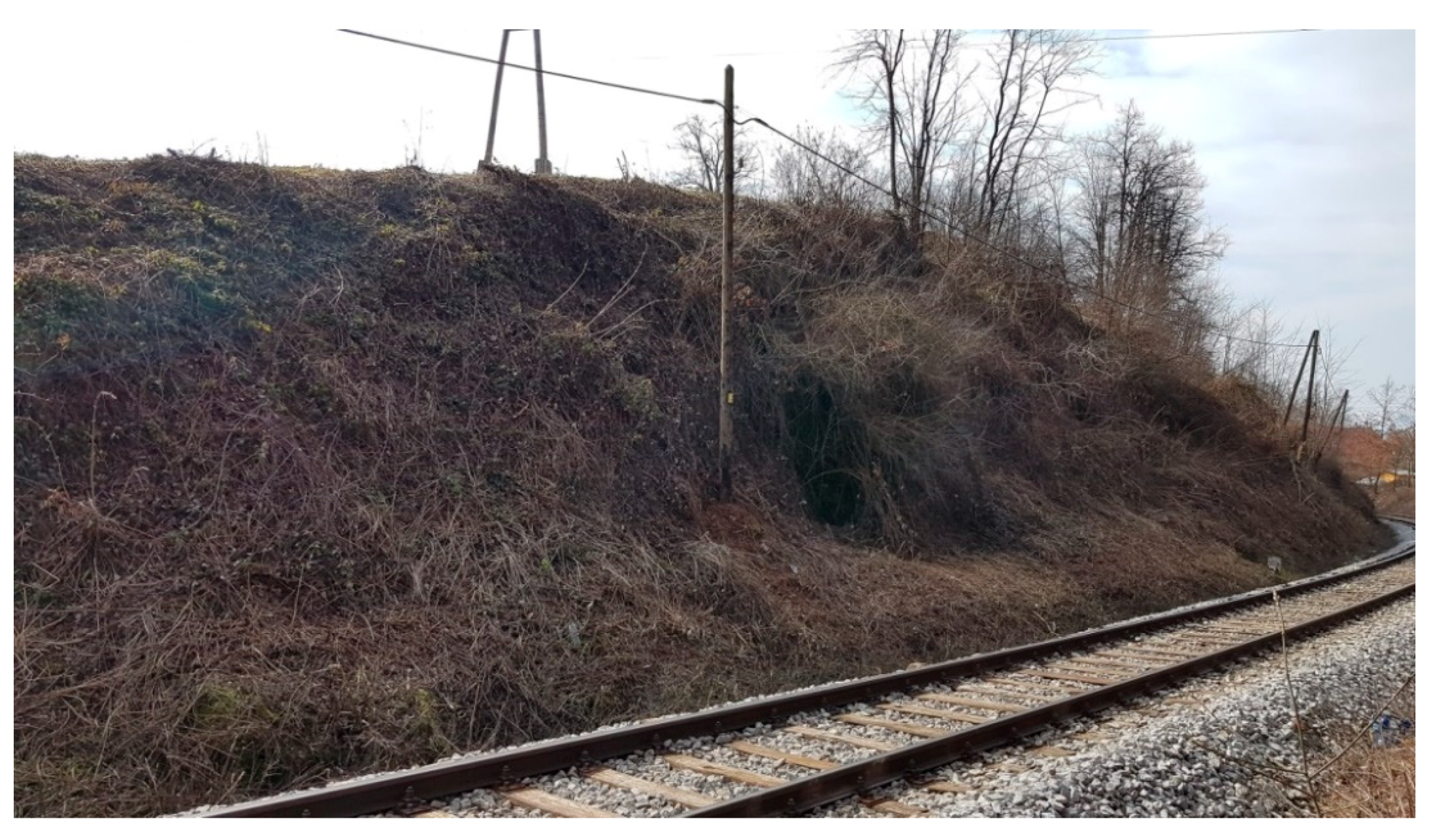
In the region between Ljubljana and Novo Mesto, there is a landslide risk that endangers the safety of a railway line. The instability of the slope was already evident from the geological and geomechanical mapping of the site [43]. Subsequently, after carrying out a detailed geomechanical investigation of the railway zone, the final pilot structure location was selected in the exact location shown in Figure 1.
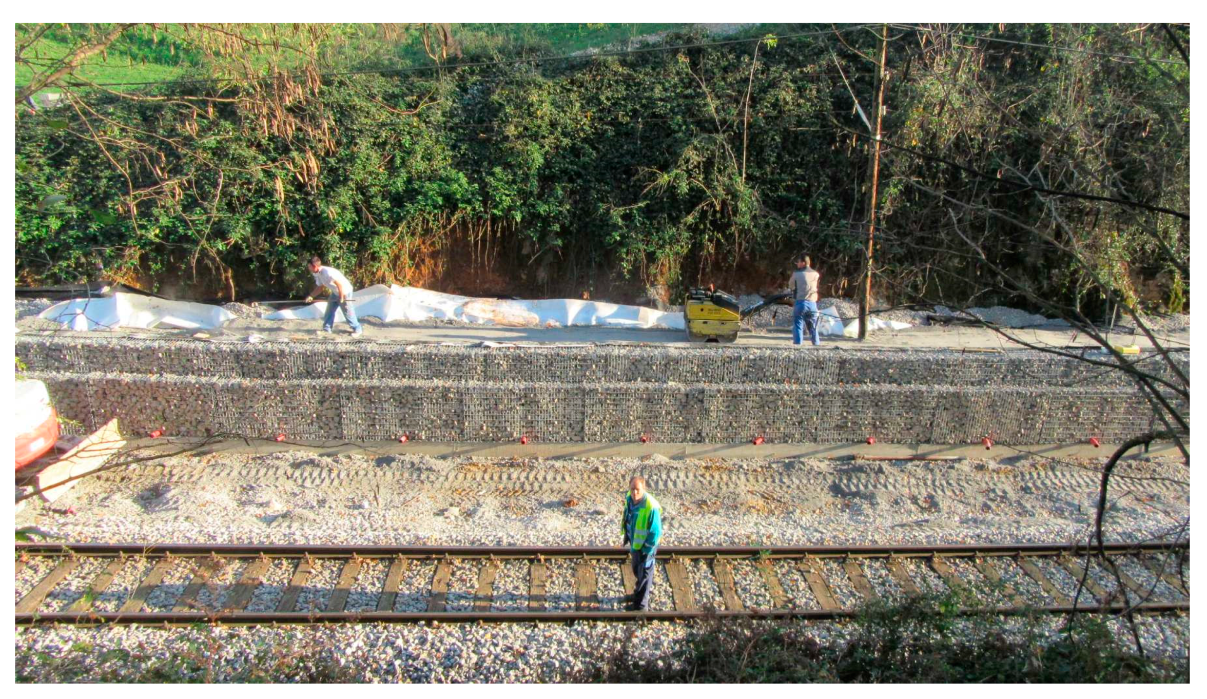
Construction work started in August 2018. The length of the structure was 50 m, with a height of 1.5 m. The retaining wall was made of gabions and backfill material with composite. The width of the backfill material between the gabions and landslide slope was between 2 and 3.5 m.
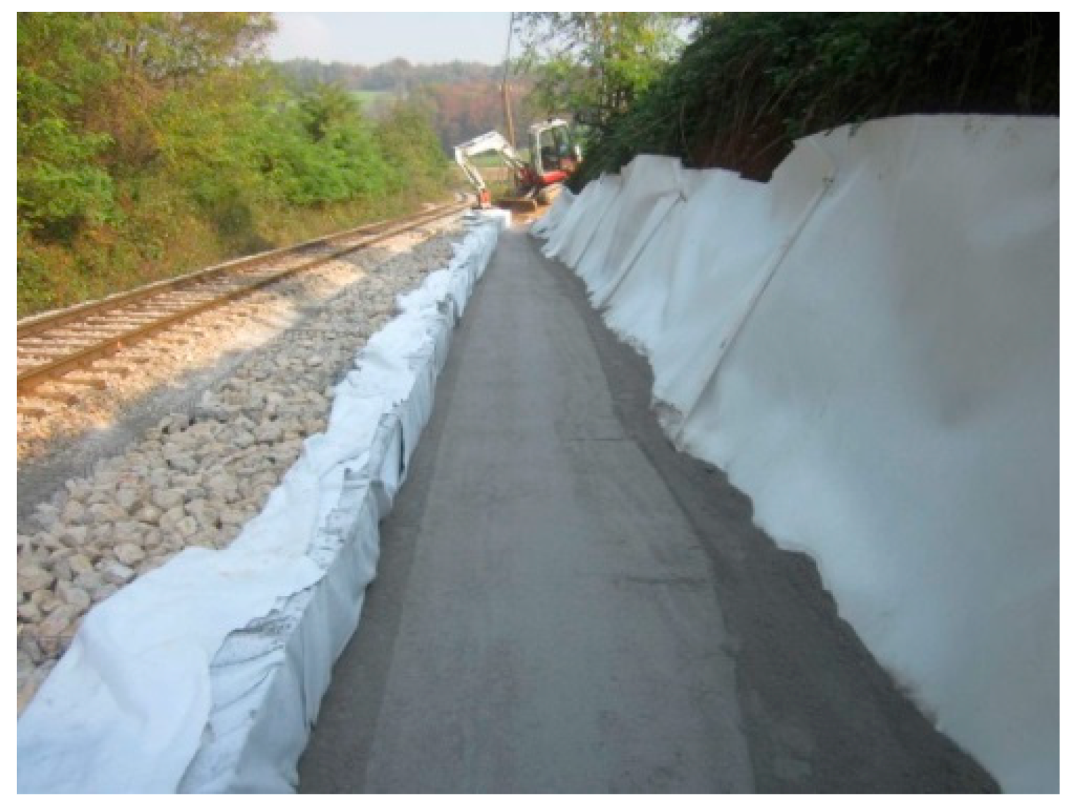
The mixture was prepared at the VIPAP facility from DPA and DS and transported to the construction site, located 70 km from VIPAP’s facility. Mixing was performed by a stirrer (TERREX, Norwalk, CA, USA) for at least 15 min. The composite was transported to the construction site and subsequently compacted to the required density (Figure 2) in a 30 cm thick layer by a compactor (BOMAG, Boppard, Germany). For the whole structure, 100 t of the mixture was compacted into nine layers (Figure 3).
Special attention was paid to the drainage system since the composite is impermeable. A drainage system was installed under the backfill and at the contact point between the backfill and the landslide slope.
Each compacted layer was tested at the construction site for dry density and moisture content (γd, w) according to TSC 06.711 [44] by a nuclear soil moisture density gauge (TROXLER, Ettenheim, Germany) and for dynamic deformation (Evd) modules according to TSC 06.720 [45] (2003), by a dynamic plate (ZORN, Stendal, Germany). In order to perform the leaching procedure, according to SIST EN 1744-3 [46], samples were collected from the last layer. The leachates were analyzed by inductively coupled plasma mass spectrometry (ICP-MS) and UV-Vis spectrophotometry. Samples were also taken to verify the shear characteristics of the composite according to the standard SIST EN ISO 17892-10 [41].
2.2.4. Long-Term Monitoring
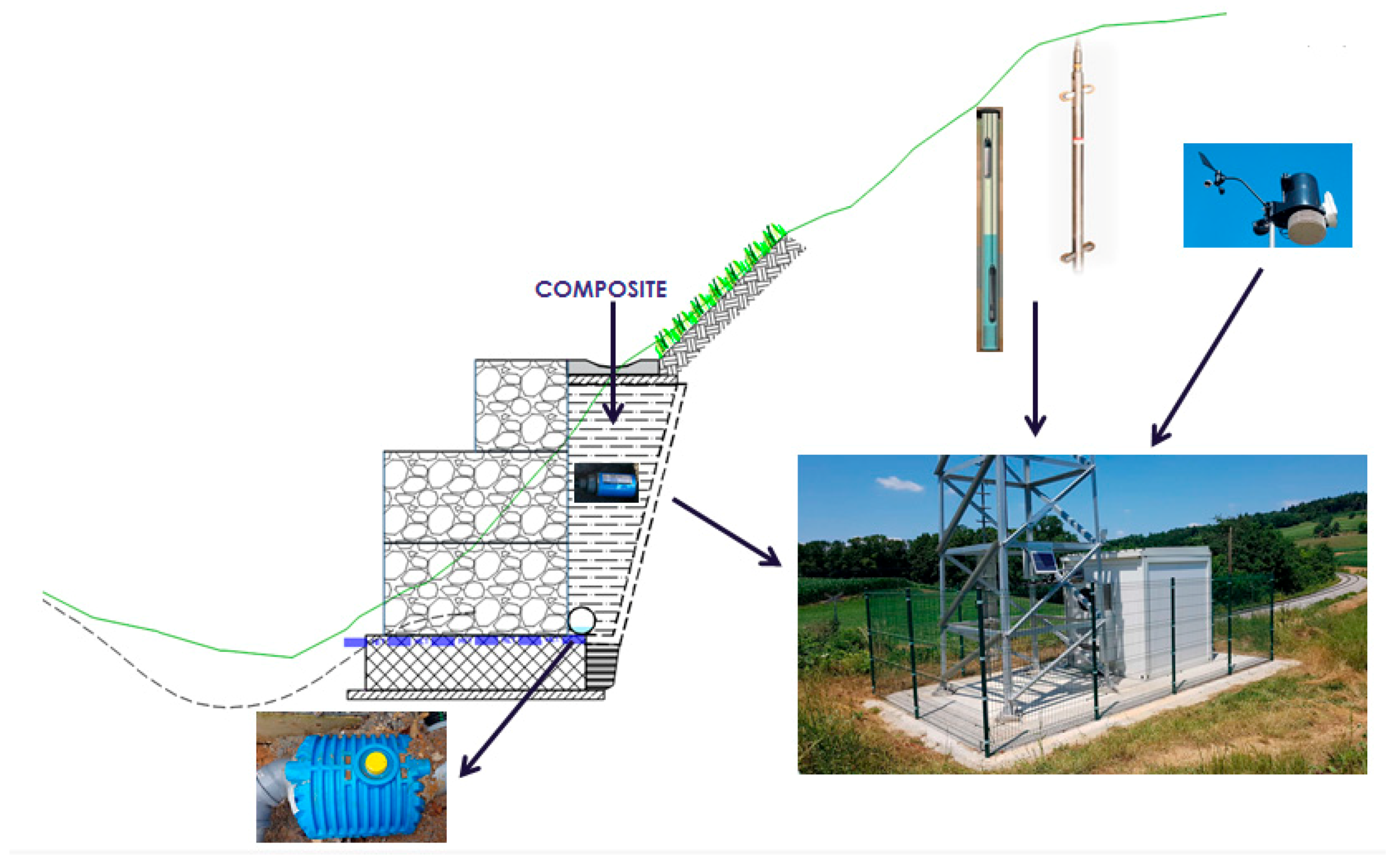
For long-term monitoring, an automatic station was placed at the construction site (Figure 4). It collects measurements from the weather station, inclinometers, piezometers from boreholes, and moisture and temperature probes installed in the backfill material behind the retaining wall made from gabions.
A soil moisture probe (Imko, Ettlingen, Germany) was installed 90 cm below the surface, and temperature sensors were installed 30, 60, and 90 cm below the surface of the composite.
For environmental monitoring, a water tank was built at the end of the retaining wall. The water flowing from the drainage system between the gabions and the composite (backfill material) was collected in a plastic tank and taken for chemical analyses.
The displacements that can occur above the retaining wall structure were monitored with a manual inclinometer (Interfels, Ulm, Germany), while those of the entire structure (specifically those of the gabions and the foundation) were monitored by a laser scanner (Leica, Aarau, Switzerland).
3. Results and Discussion
Preliminary investigations of two types of composites were performed in the laboratory, and the composite with the most suitable properties was selected for implementation.
3.1. Raw Material
Chemical analyses showed that the major oxide of DSA (Table 3) was CaO, accounting for almost 50 wt%. More than a quarter of DSA mass was lost after the LOI treatment. The most abundant oxides of DS were CaO (accounted for almost one-third) and the measured LOI was more than 50 wt%. High values of LOI were due to high fibre or other organic compounds. Elements such as Si, Al, and Mg were in concentrations below 0.25 wt%. Higher CaO content in DSA and DS was due to the use of fillers and coatings in the deinking process of the production of new paper from used paper. Also, higher CaO led to the higher pozzolanic reactivity of the composite made from DSA and DS.
The physical and mechanical properties of DSA and DS are presented in Table 4. DSA is a dry material, while the water content of DS ranges between 45% and 50%. In comparison with DS, the specific gravity of DSA was higher by about 20%. A standard Proctor test (SPP) showed that the optimal water content (wopt) and maximal dry density (γd,max) were higher for DS. The unconfined compressive strength of DSA is between 300 and 500 kPa, which is in the range of very stiff soil according to the criteria for virgin materials. DS is a softer material in the range of stiff soil. Both materials were nonplastic.
3.2. Results of Preliminary Laboratory Tests
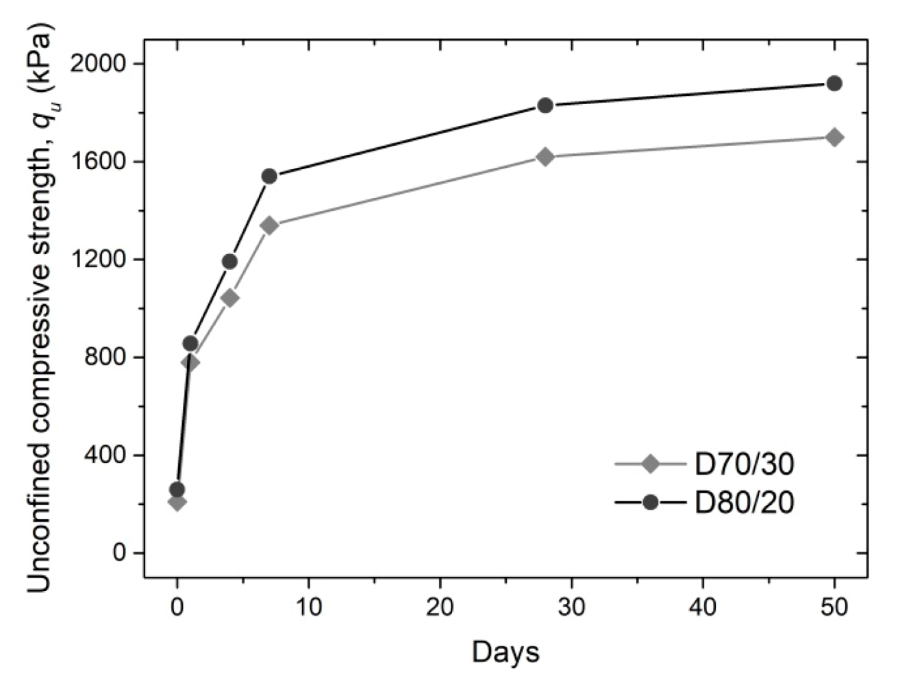
3.2.1. Unconfined Compressive Strength—qu
The unconfined compressive strength decreased (Figure 5) with a higher quantity of DS in the composites and increased with curing time. The tests performed immediately after compaction showed relatively similar values of qu (0.2–0.3 MPa), independent of the composition. After one day of curing, composites with higher percentages of DSA showed higher qu values, accounting for the more intense hydration process in those composites.
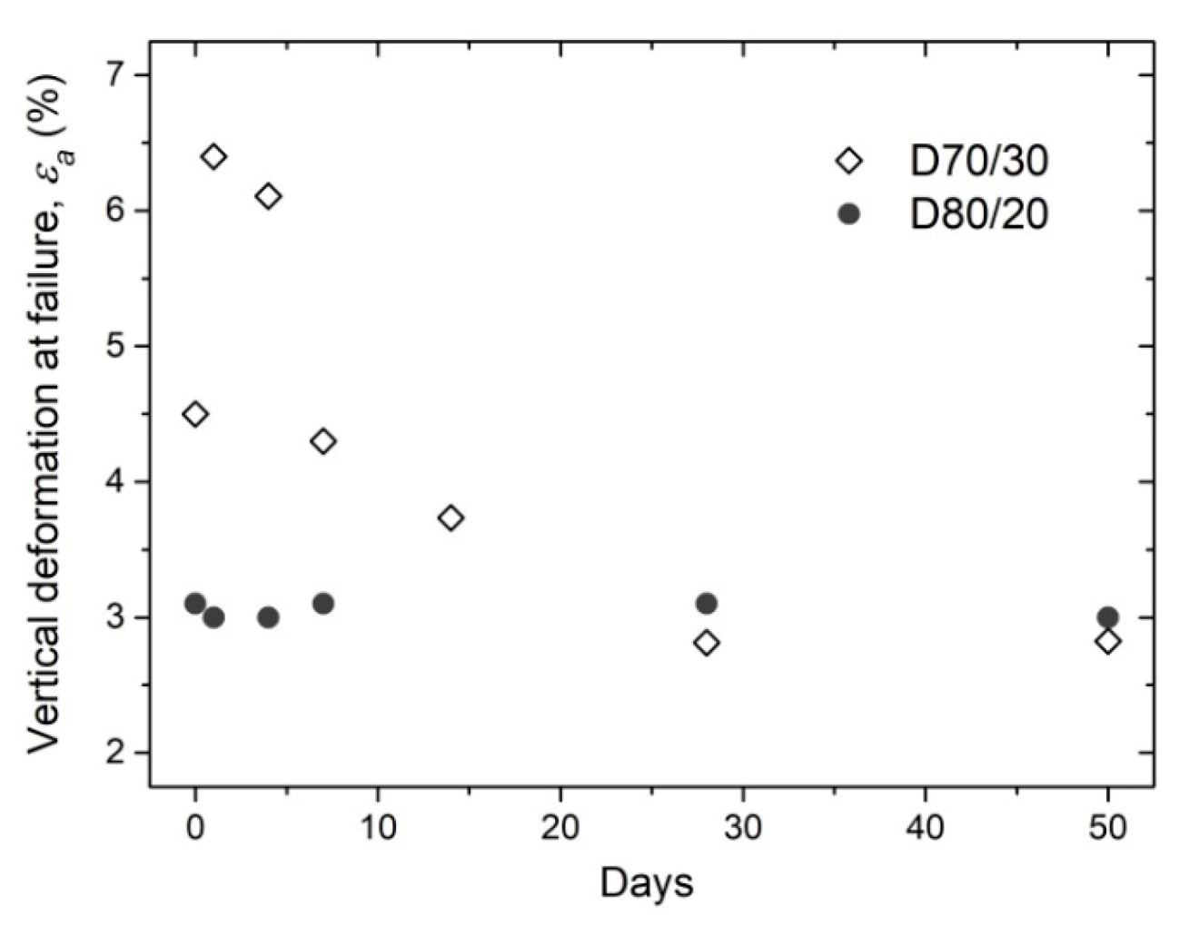
The results of the vertical deformation at the sample failure during the uniaxial compressive test are shown in Figure 6. With an increasing content of DS in the composite, the vertical deformations increased. This is reflected in the rapid breaking and very small elastic deformations, i.e., the brittle deformation behavior of the D80/20. By contrast, ductile behavior was observed in the D70/30.
The curing time has a strong influence on the vertical deformation (εA) at failure. While this is not as obvious with D80/20, in the case of D70/30, the εA at failure increased rapidly in one day and then decreased over time. After 28 days, the εA was almost the same for both composites. This points to the fact that the failure mode of mixtures changes from ductile to brittle between the first and fourth days of curing.
Even after a retaining wall is built, some deformations can still occur in the structure because of the stabilization processes in the landslide mass, especially in the early days of construction. Because of this, it is desirable for a backfill material to possess higher elasticity and, at the same time, have enough strength to prevent landslides.
3.2.2. Time Effect
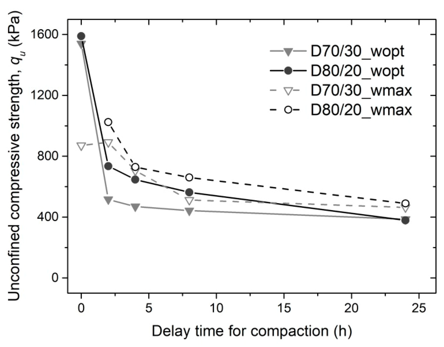
The results of the investigation of the impact of the delay between mixing and compacting (Figure 7) showed that qu decreased with the increased time between them. The highest values of qu were seen in samples prepared at the wopt (Figure 8) and compacted immediately after mixing. For samples compacted 4 h after mixing, higher qu values were measured for composites prepared at the wmax. The hydration process dried the mixtures and after 4 h resulted in a lower qu for mixtures with lower water content. After 24 h, no difference could be observed in qu. Based on the results, it can be concluded that the mixture compacted immediately must be moistened to the wopt. For a mixture that will be compacted after 4 h due to transport, it is more appropriate to moisten it to the wmax.
The results of these tests are essential to determine the methods of mixing, transport, and installation of the mixture on the construction site and to assess the maximum distance between the composite production site and the composite construction site. The results from the laboratory and field tests showed that the mixture has to be moistened above the wopt before transport. It is a very important requirement for the installation procedure. If the mixture at the construction site does not have a high enough water content, it will not be properly compacted, and the strength of the installed layer will be lower than it has to be, according to the legislation. Three to five percent of the water is consumed during the hydration process of DSA.
3.2.3. Standard Proctor Tests (SPP)
The results of the SPP showed that the optimal water content (wopt) increases slightly with a higher percent of DSA in composites (Figure 8). A higher percentage of DSA required more water for the hydration process in the composite. A similar trend was observed for maximal dry density as it increased from 0.96 Mg/m3 in D70/30 to 0.99 Mg/m3 in D80/20.
The main difference between the investigated composites and the natural gravel material is the density. The γd,max for a natural gravel material is 2.3 Mg/m3 on average, while the investigated composites show a much lower γd,max. This physical characteristic enables the use of the investigated composites in low-bearing-capacity foundation soils. Such a backfill material is light and does not cause large settlement, as does the heavy virgin gravel material. This is one of the important advantages of using the investigated composites as a backfill material for geotechnical structures in regions with difficult geotechnical conditions.
3.2.4. Frost Resistance
According to the Slovenian National Technical Specifications for roads, TSC 06.320 [40] on freeze/thaw resistance, the freeze ratio has to be more than 0.7 (the ratio between the unconfined compressive strength of exposed samples and curing samples at atmosphere-controlled conditions).
Both composites are above the limit value of 0.7. Based on these results, it can be concluded that this material could be used as a backfill material even in the top meter below the surface. That is the depth of freezing at the pilot structure’s location.
3.2.5. Shear Properties
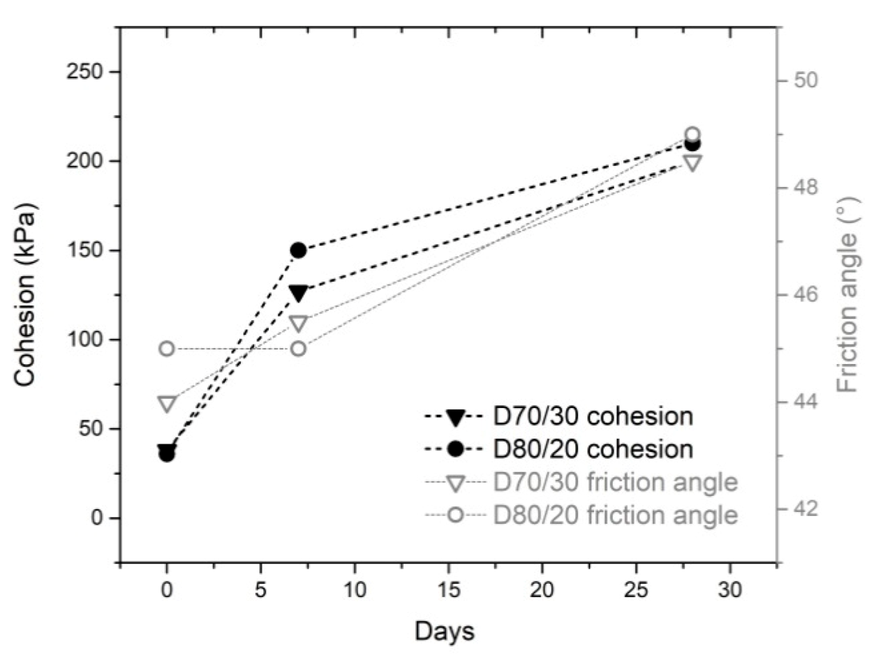
The results of a friction angle (f) and cohesion (c) analysis showed that shear characteristics increase with the decrease in DS content of composites, but after 28 days, the differences were not so obvious (Figure 9). The shear characteristics are higher in comparison with the natural gravel backfill material conventionally used for retaining wall structures. The friction angle for gravel is around 30° with no cohesion. The high shear properties of the composite allow for the construction of a thinner retaining wall than would be needed if virgin gravel material was used. These characteristics are very important, especially for retaining structures near railway lines, where there is generally not enough space for large geotechnical structures.
3.2.6. Composite Used for Backfill Material
Based on the results of the laboratory tests, the composite D70/30 was chosen for use as a backfill material behind the retaining wall structure. The composite has a high enough qu even when compacted 4 h after mixing, and at the same time allows small deformations before cracking. It is ductile enough to sustain small deformations behind the retaining wall in case of landslides. The composite has high enough freeze/thaw resistance to withstand extreme weather conditions. Shear properties are higher in comparison with virgin material (gravel). Because of these properties, the retaining wall structure can be lower and cheaper. Instead of 2 m, the gabion structure that was built had to be only 1.5 m high.
3.3. Results from the Pilot Structure
3.3.1. Field Tests
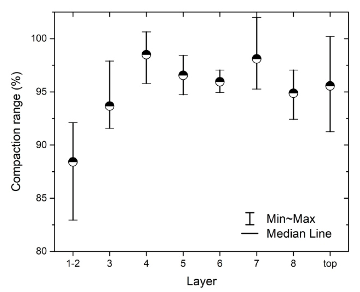
According to the technical specification TSC 06.711 [44], the average compaction of the last layer has to be at least 95% γd,max. The results of the compaction tests of the installed composite D70/30 showed that only the first three layers were compacted below 95% γd,max (Figure 10). The reason for the lower compactness in the first layers is the uncompacted drainage layer under the composite. In all other layers, a higher compaction degree was measured. Measurements confirmed that the quality of the installed composite was within the requirements of the technical specifications.
3.3.2. Laboratory Tests of Samples from the Pilot Retaining Wall
Shear tests of the samples taken from the composite at the construction site reach high enough shear properties. The results are similar to the results from the preliminary laboratory investigation; even cohesion increases significantly after 28 days. In the design project [43] for the stability analysis, the design parameters were lower, especially for cohesion, which means that the safety factor of the structure was higher. Shear characteristic values obtained from the in-built composite are gathered in Table 5.
The new composite had significantly higher shear characteristics compared to a natural gravel backfill material. The shear properties of the composite are similar to the shear properties of soft rock. If virgin gravel material is used as the backfill, a larger retaining wall structure should be designed to prevent landslide movement, as was confirmed in the project design [43].
A leaching test of the samples taken from the structure showed (Table 6) that none of the components in the water exceeded the limits established by Slovenian legislation (UL RS, No. 10/14, 22 February 2014). The installed mixture does not have an adverse environmental impact because it is impermeable, and water from the composite does not leach hazardous substances. For the composite, very low permeability (only 2.2 × 10⁻¹⁰ under the load of 50 kPa) was measured in the laboratory.
3.4. Results of the Long-Term Monitoring
3.4.1. Stability of the Landslide
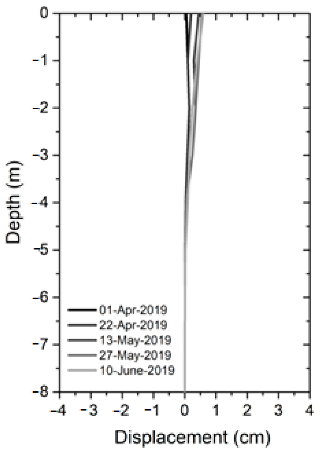
To ensure the safety of passengers and cargo, the landslide was stabilized with a retaining wall structure (Figure 11). Deformations of the slope above the railway line were measured with an inclinometer. The measurements did not indicate any displacements because the retaining wall successfully stopped the landslide (Figure 12).
For the retaining wall structure, measurements were taken by a laser scanner. The measurements showed that the foundation of the retaining wall was stable. Both the measurements of the retaining wall and the measurements of the landslide deformations showed that the landslide was successfully stabilized.
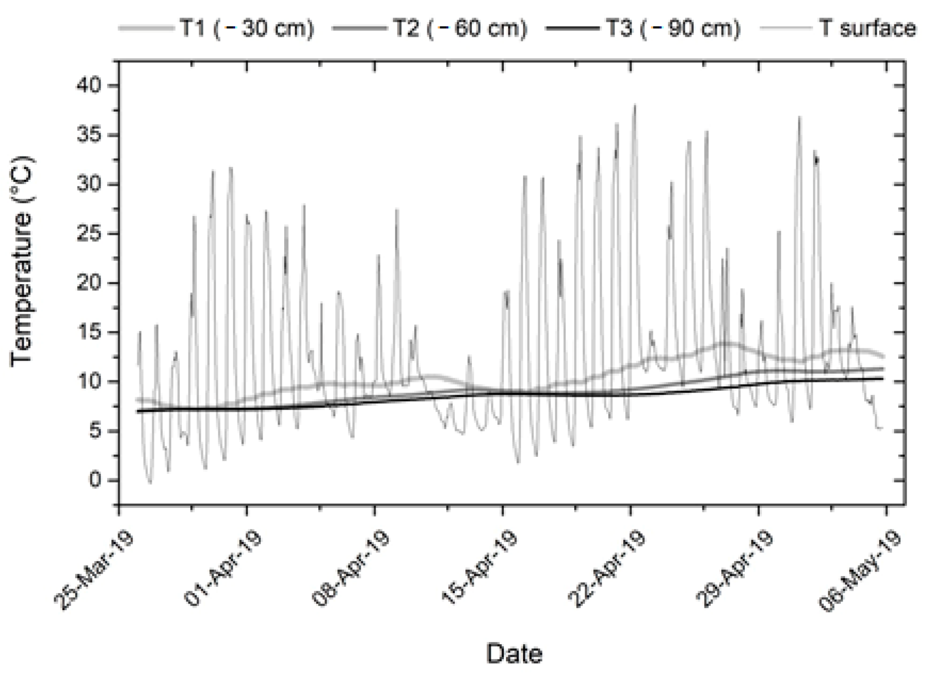
The composite used has to be sustainable and resistant to weather changes. The results of the temperature measurements showed that the weather does not influence the temperature of the composite significantly (Figure 13). Some correlation with the outside temperature (T) can be observed in the sensor that is 30 cm below the surface (T1), while the temperatures at 60 cm (T2) and 90 cm (T3) below the surface remained more or less stable despite the fluctuation of the outside temperature.
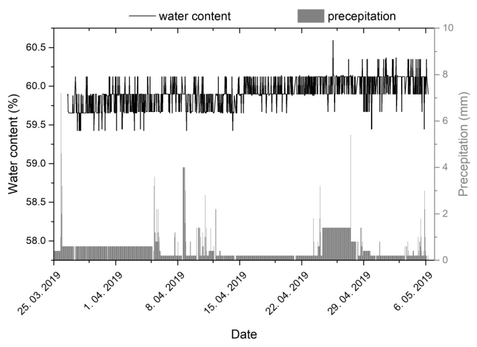
The water content of the composite at the time of compaction was 57% and is currently around 47%. Comparison with the precipitation showed that the composite is impermeable because there was no correlation between the water content and precipitation (Figure 14). The temperature and water content sensors showed that the weather does not have an influence on the composite quality.
3.4.2. Environmental Monitoring
Samples were taken from the water tank and tested in an accredited chemical laboratory. The results show that the composite did not have a negative influence on the water quality since the concentration of none of the tested parameters exceeded the limits set by Slovenian legislation UR RS No. 98/15 (Table 7).
4. Conclusions
A new composite from paper residues was developed as a backfill material for retaining wall structures. Preliminary tests were performed in an accredited geomechanical laboratory, and the results were later verified with field and laboratory measurements on a pilot structure.
A composite has to have geomechanical properties that are high enough to be used as a backfill material behind a retaining wall structure in an unstable area near a railway line threatened by landslides. Several mixtures with different contents of DS and DSA were initially tested to choose the optimal composite with the proper geomechanical properties. Two of them were studied in detail within the present research to estimate the effect of their composition upon particular basic characteristics.
No studies to date have dealt with the changing strength characteristics of material during mixing and installation. The time of transport is an important parameter for using this mixture as a backfill material. Results from the laboratory showed that the mixture has to be moistened above the wopt before being transported and used at the construction site within 4 h.
Based on the laboratory results, it was decided to use composite D70/30 as the backfill material for the retaining wall. The composite is a new mixture that has not yet been tested in a laboratory or installed in the retaining wall structure at the construction site. The composite with 30% DS had a high enough qu and shear strength but allowed small deformations before failure. The high shear characteristics of the composite allowed for a slimmer retaining structure to support the unstable slope behind it. At the same time, the DS in the composite enabled ductile behavior of the structure and prevented it from brittle failure.
In 2018, the composite D70/30 was used as a backfill material of the retaining wall structure built by gabions in the south part of Slovenia, near the railway line, for landslide stabilization. All laboratory and field tests confirmed the physical characteristics measured in the research phase and confirmed that the environmental requirements are being reached.
At the construction site, the material was installed in 30 cm layers. Each layer was compacted and controlled to reach the optimal moisture and maximum density. Before, during, and after the construction, landslide stability was assessed, and environmental monitoring was performed. With the test results from the pilot structure presented in this paper, the technology of mixing and compacting was improved. Mixing is usually not a problem in the laboratory, but at a construction site, a large quantity of material has to be mixed with the proper technology. The monitoring system confirmed that the retaining wall with the composite stabilizes the landslide near the railway. The composite was an impermeable material, and precipitation did not influence its stability. As the area covered with such an impermeable layer was not very wide, the impact on the groundwater recharge was limited. However, one should consider such a structure as a groundwater barrier that disturbs shallow groundwater flows. Thus, the use of this kind of structure should be combined with a properly designed drainage system, which minimizes the effect of groundwater disturbance. In the case of the retaining structure presented within this paper, vertical and horizontal drainage were employed to enable effective drainage of water behind the retaining structure.
On the other hand, the low density of the composite from paper residues also has several advantages. There is great potential for its use in construction on soft ground. In such a case, the utilization of very light materials, like the new composite, could prevent large settlement.
The pilot retaining wall structure represents a practical case for future investors, designers, and construction companies to encourage them to use recycled materials from the paper industry instead of virgin materials. The new composite and its installation technology were successfully tested. The presented circular case between the paper industry and the construction sector shows the advantages for both sides. Instead of disposing of the waste in a landfill for a very high price (in Slovenia, 80–150 €/tonne), the paper manufacturer processes the waste into a composite for a retaining wall structure. Contractors, meanwhile, get a composite that is cheap and has better deformation properties than the virgin material.
5. Patents
The Slovenian Technical Approval STS—1870011 was granted for this product.
Author Contributions
Conceptualization, K.F.B. and S.L.; methodology, B.L., K.F.B. and S.L.; formal analysis, B.L. and K.F.B.; investigation, K.F.B., S.L. and B.L.; resources, K.F.B., S.L. and B.L., writing—original draft preparation, K.F.B.; writing—review and editing, S.L. and B.L.; supervisor, K.F.B., funding acquisition, K.F.B. All authors have read and agreed to the published version of the manuscript.
Funding
This research was funded by the European Union, co-financed by the Horizon 2020 Research and Innovation Programme under grant agreement no. 730305, project Paperchain and the ARRS financial support from the research core funding No. P2-0273, Building structures and materials.
Institutional Review Board Statement
Not applicable.
Informed Consent Statement
Not applicable.
Data Availability Statement
Data available in a publicly accessible repository.
Conflicts of Interest
The authors declare no conflict of interest.
References
- UEPG. Annual Review 2017–2018; UEPG: Brussels, Belgium, 2018. [Google Scholar]
- Oyedele, L.O.; Ajayi, S.O.; Kadiri, K.O. Use of recycled products in UK construction industry: An empirical investigation into critical imepiments and strategies for improvement. Resour. Conserv. Recycl. 2014, 93, 23–31. [Google Scholar] [CrossRef]
- Poulikakos, L.D.; Papadaskalopoulou, C.; Hofko, B.; Gschosser, F.; Falchetto, A.C.; Bueno, M.; Arraigada, M.; Sousa, J.; Ruiz, R.; Petit, C.; et al. harvesting the unexplred potential of European waste material for road construction. Resour. Conserv. Recycl. 2017, 116, 32–44. [Google Scholar] [CrossRef]
- Garside, M. Paper Industry—Statistics & Facts. Statista. 2019. Available online: https://0-www-statista-com.brum.beds.ac.uk/topics/1701/paper-industry/Published (accessed on 4 January 2021).
- Zhang, C.; Jiang, G.; Liu, X.; Wang, Z. Lateral displacement of silty clay under cement−fly ash−gravel pile−supported embankments: Analytical consideration and field evidence. J. Cent. South Univ. 2015, 22, 1477–1489. [Google Scholar] [CrossRef]
- Monte, M.C.; Fuente, E.; Blanco, A.; Negro, C. Waste management from pulp and paper production in the European Union. Waste Manag. 2009, 29, 293–308. [Google Scholar] [CrossRef] [Green Version]
- IPPC. Council Directive 96/61/EC of 24 September 1996 concerning Integrated Pollution Prevention and Control (IPPC). Off. J. 1996, 257, 10. [Google Scholar]
- EAA. The Roadmap to a Resource Efficient Europe (EU COM 2011/571); European Commission: Brussels, Belgium, 2011. [Google Scholar]
- Fischer, C.; Lehner, M.; McKinnon, D.L. Overview of the Use of Landfill Taxes in Europe. 2012. Available online: https://ec.europa.eu/environment/waste/pdf/strategy/3.%20%20Christian%20Fischer%20EEA%20Landfill%20taxes.pdf (accessed on 4 January 2021).
- Watkins, E.; Hogg, D.; Mitsios, A.; Mudgal, S.; Neubauer, A.; Reisinger, H.; Troeltzsch, J.; Van Acoleyen, M. Use of Economic Instruments and Waste Management Performances; Bio Intelligence Service S.A.S: Paris, France, 2012. [Google Scholar]
- Bajpai, P. Recycling and Deinking of Recovered Paper; Elsevier: Amsterdam, The Netherlands, 2012. [Google Scholar]
- Saeli, M.; Senff, L.; Tobaldi, D.M.; La Scalia, G.; Seabra, M.P.; Labrincha, J.A. Innovative Recycling of Lime Slaker Grits from Paper-Pulp Industry Reused as Aggregate in Ambient Cured Biomass Fly Ash-Based Geopolymers for Sustainable Construction Material. Sustainability 2019, 11, 3481. [Google Scholar] [CrossRef] [Green Version]
- Ferreira, I.A.; Fraga, M.C.; Godina, R.; Barreiros, M.S.; Carvalho, H. A Proposed Index of the Implementation and Maturity of Circular Economy Practices—The Case of the Pulp and Paper Industries of Portugal and Spain. Sustainability 2019, 11, 1722. [Google Scholar] [CrossRef] [Green Version]
- Gabriel, M.; Schöggl, J.P.; Posch, A. Early Front-End Innovation Decisions for Self-Organized Industrial Symbiosis Dynamics—A Case Study on Lignin Utilization. Sustainability 2017, 9, 515. [Google Scholar] [CrossRef] [Green Version]
- García, R.; de la Villa, R.V.; Rodríguez, O. Mineral phases formation on the pozzolan/lime/water system. Appl. Clay Sci. 2009, 43, 331–335. [Google Scholar] [CrossRef]
- Fernández, R.; Nebreda, B.; de la Villa, R.V.; García, R.; Frías, M. Mineralogical and chemical evolution of hydrated phases in the pozzolanic reaction of calcined paper sludge. Cem. Concr. Compos. 2010, 32, 775–782. [Google Scholar] [CrossRef]
- Segui, P.; Aubert, J.E.; Husson, B.; Measson, M. Characterization of wastepaper sludge ash for its valorization as a component of hydraulic binders. Appl. Clay Sci. 2012, 57, 79–85. [Google Scholar] [CrossRef]
- Wu, H.; Yin, J.; Bai, S. Experimental investigation of utilizing industrial waste and byproduct material in controlled low strength materials (CLMS). Adv. Mater. Res. 2013, 639–640, 299–303. [Google Scholar] [CrossRef]
- Bui, K.N.; Satomi, T.; Takahashi, H. Influence of industrial by-products and waste paper sludge ash on properties of recycled aggregate concrete. J. Clean. Prod. 2019, 214, 403–418. [Google Scholar] [CrossRef]
- Khalid, N.; Mukri, M.; Kamarudin, F.; Arshad, M.F. Clay Soil Stabilized Using Waste Paper Sludge Ash (WPSA) Mixtures. EJGE 2012, 12, 1215–1225. [Google Scholar]
- Mavroulidou, M. Use of waste paper sludge ash as a calcium-based stabiliser for clay soils. Waste Manag. Res. 2017, 36, 1066–1072. [Google Scholar] [CrossRef] [PubMed]
- Dharan, R.B. Effect of Waste Paper Sludge Ash on Engineering Behaviors of Black Cotton Soils. Int. J. Earth Sci. Eng. 2016, 9, 188–191. [Google Scholar]
- Lu, Q.M.; Zhang, Y.X.; Zhang, R.L.; Sun, W.B. Analysis of mechanical properties and microstructure of sludge-ash and cement cementitious system. J. Saf. Environ. 2019, 19, 308–311. [Google Scholar]
- Ahmadi, B.; Al-Khaja, W. Utilization of paper waste sludge in the building construction industry. Resour. Conserv. Recycl. 2001, 21, 105–113. [Google Scholar] [CrossRef]
- Oprčkal, P.; Mladenović, A.; Zupančič, N.; Ščančar, J.; Milačič, R.; Zala Serjun, V. Remediation of contaminated soil by red mud and paper ash. J. Clean. Prod. 2020, 256, 120440. [Google Scholar] [CrossRef]
- Lisbona, A.; Vegas, I.; Ainchil, J.; Riso, C. Soil Stabilization with Calcined Paper Sludge: Laboratory and Field Tests. J. Mater. Civ. Eng. 2012, 24, 666–673. [Google Scholar] [CrossRef]
- Vestin, J.; Arm, M.; Nordmark, D.; Lagerkvist, A.; Hallgren, P.; Lind, B. Fly ash as a road construction material. In WASCON; Arm, M., Vandecasteele, C., Heynen, J., Suer, P., Lind, B., Eds.; SGI: Gothenburg, Sweden, 2012; pp. 1–8. [Google Scholar]
- Vegas, I.; Urreta, J.; Frias, M.; Garcia, R. Freeze–thaw resistance of blended cements containing calcined paper sludge. Constr. Build. Mater. 2009, 23, 2862–2868. [Google Scholar] [CrossRef]
- Sadique, M.; Al-Nageim, H.; Atherton, W.; Seton, L.; Dempster, N. Analytical investigation of hydration mechanism of a non-Portland binder with waste paper sludge ash. Constr. Build. Mater. 2019, 211, 80–87. [Google Scholar] [CrossRef]
- Vashistha, P.; Kumar, V.; Singh, S.K.; Dutt, D.; Tomar, G.; Yadav, P. Valorization of paper mill lime sludge via application in building construction materials: A review. Constr. Build. Mater. 2019, 211, 371–382. [Google Scholar] [CrossRef]
- Fava, G.; Ruello, M.L.; Corinaldesi, V. The properties of wastepaper sludge ash and its generic applications. J. Mater. Civ. Eng. 2011, 23, 772–776. [Google Scholar] [CrossRef] [Green Version]
- Singh, D.; Kumar, A. Performance Evaluation and Geo-Characterization of Municipal Solid Waste Incineration Ash Material Amended with Cement and Fibre. Int. J. Geosynth. Ground Eng. 2017, 3, 16. [Google Scholar] [CrossRef]
- Mauko, P.A.; Oprčkal, P.; Mladenović, A.; Zapušek, P.; Urleb, M.; Turk, J. Comparative Life Cycle Assessment of possible methods for the treatment of contaminated soil at an environmentally degraded site. J. Environ. Manag. 2016, 218, 497–508. [Google Scholar] [CrossRef]
- Kinnarinen, T.; Golmaei, M.; Jernström, E.; Häkkinen, A. Removal of hazardous trace elements from recovery boiler fly ash with an ash dissolution method. J. Clean. Prod. 2019, 209, 1264–1273. [Google Scholar] [CrossRef]
- European Commission. Commission Decision of 3 May 2000 Replacing Decision 94/3/EC Establishing a List of Wastes Pursuant to Article 1(a) of Council Directive 75/442/EEC on Waste and Council Decision 94/904/EC Establishing a List of Hazardous Waste Pursuant to Article 1(4) of Council Directive 91/689/EEC on Hazardous Waste (Notified under Document Number C(2000) 1147). 2000. Available online: https://eur-lex.europa.eu/legal-content/EN/TXT/?uri=CELEX:02000D0532-20150601 (accessed on 4 January 2021).
- SIST EN 196-2:2013. Method of Testing Cement—Part 2: Chemical Analysis of Cement; SIST: Ljubljana, Slovenia, 2013. [Google Scholar]
- SIST EN ISO/IEC 17025:2017. General Requirements for the Competence of Testing and Calibration Laboratories; SIST: Ljubljana, Slovenia, 2017. [Google Scholar]
- SIST EN 13286-2:2010/AC:2013. Unbound and Hydraulically Bound. Mixtures—Part 2: Test. Methods for Laboratory Reference Densityand Water Content—Proctor Compaction; SIST: Ljubljana, Slovenia, 2013. [Google Scholar]
- SIST EN 13286-41:2004. Unbound and Hydraulically Bound. Mixtures. Test. Method for Determination of the Compressive Strength of Hydraulically Bound. Mixtures; SIST: Ljubljana, Slovenia, 2004. [Google Scholar]
- TSC 06.320:2001. Vezane Spodnje Nosilne Plasti s Hidravličnimi Vezivi; DRSI: Ljubljana, Slovenia, 2001. [Google Scholar]
- SIST EN ISO 17892-10. Geotechnical Investigation and Testing—Laboratory Testing of Soil—Part 10: Direct Shear Tests; SIST: Ljubljana, Slovenia, 2019. [Google Scholar]
- SIST EN ISO 17892:11. Geotechnical Investigation and Testing—Laboratory Testing of Soil—Part 11: Permeability Tests; SIST: Ljubljana, Slovenia, 2019. [Google Scholar]
- Fifer, K.B. Geološko Geotehnično Poročilo; ZAG: Ljubljana, Slovenia, 2018. [Google Scholar]
- TSC 06.711:2001. Meritev Gostote in Vlage. Postopek z Izotopskim Merilnikom; DRSI: Ljubljana, Slovenia, 2001. [Google Scholar]
- TSC 06.720:2003. Meritve in Preiskave. Deformacijski Moduli Vgrajenih Materialov; DRSI: Ljubljana, Slovenia, 2003. [Google Scholar]
- SIST EN 1744-3:2002. Tests for Chemical Properties of Aggregates—Part 3: Preparation of Eluates by Leaching of Aggregates; SIST: Ljubljana, Slovenia, 2002. [Google Scholar]
Figure 1.
Location of the pilot structure.

Figure 2.
Compacted layer of the composite.

Figure 3.
Compacting the last layer of the composite.

Figure 4.
Monitoring system.

Figure 5.
Uniaxial compressive tests results.

Figure 6.
Deformations after uniaxial compressive tests.

Figure 7.
Unconfined compressive strength of samples with delay in compaction time. wopt: optimal water content; wmax: maximal water content.
Figure 7.
Unconfined compressive strength of samples with delay in compaction time. wopt: optimal water content; wmax: maximal water content.

Figure 8.
Results of standard proctor tests (SPP) for the investigated composites.

Figure 9.
Angles of friction and cohesion for the mixtures.

Figure 10.
Results of the measurements with the neutron probe.

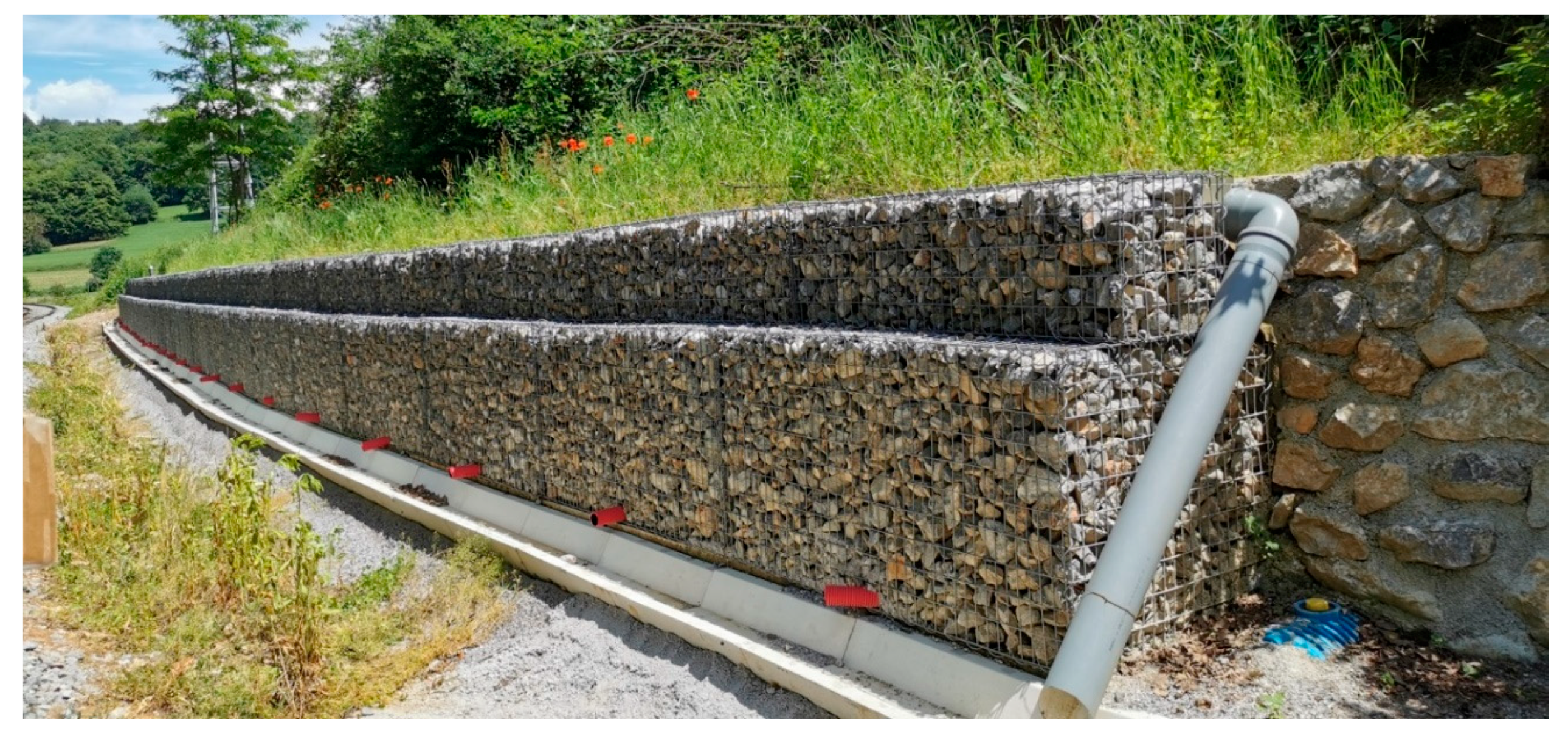
Figure 11.
Retaining wall with gabions and the composite as the backfill material.

Figure 12.
Horizontal displacements in borehole above the retaining wall.

Figure 13.
The temperature outside and in the backfill composite in the retaining wall structure (26 March 2019–10 May 2019).
Figure 13.
The temperature outside and in the backfill composite in the retaining wall structure (26 March 2019–10 May 2019).

Figure 14.
Water content in backfill material in the retaining structure vs. precipitation (26 March 2019–10 May 2019).
Figure 14.
Water content in backfill material in the retaining structure vs. precipitation (26 March 2019–10 May 2019).


Table 1.
Physical and mechanical properties of raw materials.
| Property | STANDARD |
|---|---|
| Initial Moisture Content (w) (%) | SIST EN ISO 17892-1:2015 |
| Specific Gravity (γs) (Mg/m3) | SIST EN ISO 17892-3:2016 |
| Optimum Water Content (wopt) (%) | SIST EN 13286-2:2010/AC:2013 |
| Maximum Dry Density (γd,max) (Mg/m3) | SIST EN 13286-2:2010/AC:2013 |
| Unconfined composite strength after compaction (qu) (MPa) | SIST EN 13286-41:2004 |
| Liquid Limit (LL) (%) | SIST-TS CEN ISO/TS 17892-12:2004 |
| Plastic Limit (PL) (%) | SIST-TS CEN ISO/TS 17892-12:2004 |
| Particle Size Distribution | |
| Particle (>2.5 mm) (%) | SIST EN 933-1:2012 |
| Particle (0.063–2.5 mm) (%) | SIST EN 933-1:2012 |
| Particle (0.002–0.063 mm) (%) | SIST EN ISO 17892-4:2017 |
| Particle (<0.002 mm) (%) | SIST EN ISO 17892-4:2017 |
Table 2.
Mixing proportions of the investigated mixture composites and their designations.
| Designation of the Composites | Mixing Ratios (% Dry Mass) | |
|---|---|---|
| DSA | DS | |
| D80/20 | 80 | 20 |
| D70/30 | 70 | 30 |
DSA: deinking sludge ash; DS: deinking sludge.
Table 3.
Chemical composition of raw materials.
| Raw Material | Parameter (wt%) | |||||||||||
|---|---|---|---|---|---|---|---|---|---|---|---|---|
| SiO2 | Al2O3 | Fe2O3 | CaO | P2O5 | MgO | K2O | Na2O | TiO2 | SO3 | LOI | Total | |
| DSA | 11.37 | 8.26 | 0.39 | 47.94 | 0.17 | 1.70 | 0.27 | 0.17 | 0.18 | 0.31 | 27.26 | 98.02 |
| DS | 7.27 | 5.56 | 0.24 | 31.78 | 0.06 | 1.03 | 0.16 | 0.14 | 0.11 | 0.06 | 53.41 | 99.82 |
LOI: loss on ignition.
Table 4.
Physical and mechanical properties of raw materials.
| Property | DSA | DS |
|---|---|---|
| Initial Moisture Content (w) (%) | 0 | 45–50 |
| Specific Gravity (γs) (Mg/m3) | 2.64 | 2.15 |
| Optimum Water Content (wopt) (%) | 51 | 56.5 |
| Maximum Dry density (γd,max) (Mg/m3) | 0.99 | 0.89 |
| Unconfined compressive strength after compaction (qu) (MPa) | 0.3–0.5 | 0.22 |
| Liquid Limit (LL) (%) | ||
| Plastic Limit (PL) (%) | Nonplastic | Nonplastic |
| Particle Size Distribution | ||
| Particle (>2.5 mm) (%) | 0 | - |
| Particle (0.063–2.5 mm) (%) | 13.3 | - |
| Particle (0.002–0.063 mm) (%) | 75.59 | - |
| Particle (<0.002 mm) (%) | 11.11 | - |
| D10 (mm) | 0.002 | - |
| D50 (mm) | 0.02–0.06 | - |
| D90 (mm) | 0.4–0.8 | - |
Table 5.
Shear properties of the compacted composite.
| Shear Properties | Laboratory Results | Demo Field | Design Parameter | |||
|---|---|---|---|---|---|---|
| Immediately | After Seven Days | Immediately | After Seven Days | After 28 Days | ||
| F (°) | 44 | 45 | 37 | 40 | 45 | 40 |
| c (kPa) | 12 | 42 | 35 | 45 | 200 | 40 |
Table 6.
Results from the leaching tests.
| Component | Limit | Sample One after Two Days | Sample Two after 28 Days |
|---|---|---|---|
| (mg/L) | |||
| As | 0.5 | 0.003 | 0.0033 |
| Ba | 20 | 16.04 | 8.82 |
| Cd | 0.04 | <0.002 | <0.002 |
| Cr total | 0.5 | 0.033 | <0.002 |
| Cu | 2 | 1.866 | 0.61 |
| Hg | 0.01 | 0.005 | <0.001 |
| Mo | 0.5 | 0.092 | 0.097 |
| Ni | 0.4 | 0.021 | 0.0064 |
| Pb | 0.5 | 0.005 | <0.005 |
| Sb | 0.06 | <0.001 | <0.001 |
| Se | 0.1 | 0.003 | <0.003 |
| Zn | 4 | 0.035 | <0.005 |
| Chlorides | 800 | 29.1 | 13.5 |
| Fluorides | 10 | 4.01 | 3.6 |
| Sulfates | 1000 | <10 | <10 |
Table 7.
Results of the chemical analysis of the water from the drainage system.
| Component | Limit | Water Sample April 2019 | Water Sample May 2019 | Water Sample October 2019 |
|---|---|---|---|---|
| (mg/L) | ||||
| As | 0.1 | 0.0019 | 0.0006 | 0.0017 |
| Ba | 5 | 0.0080 | 0.0073 | 0.122 |
| Cd | 0.025 | <0.0002 | <0.0002 | <0.0002 |
| Cr total | 0.5 | 0.0031 | 0.0010 | 0.011 |
| Cu | 0.5 | 0.042 | 0.011 | 0.013 |
| Hg | 0.005 | <0.0001 | <0.0001 | <0.0001 |
| Mo | 1 | 0.018 | 0.0024 | 0.0028 |
| Ni | 0.5 | 0.0011 | 0.0015 | 0.0024 |
| Pb | 0.5 | 0.0005 | 0.0006 | <0.0005 |
| Sb | 0.3 | 0.0039 | 0.0011 | 0.0017 |
| Se | 0.6 | 0.0005 | <0.0003 | 0.0003 |
| Zn | 2 | <0.0005 | 0.0016 | 0.0005 |
| Chlorides | 800 | 5.17 | 1.52 | 2.19 |
| Fluorides | 10 | 0.264 | <0.10 | 0.204 |
| Sulfates | 1000 | 19 | 2 | 14 |
Publisher’s Note: MDPI stays neutral with regard to jurisdictional claims in published maps and institutional affiliations. |
© 2021 by the authors. Licensee MDPI, Basel, Switzerland. This article is an open access article distributed under the terms and conditions of the Creative Commons Attribution (CC BY) license (http://creativecommons.org/licenses/by/4.0/).
Share and Cite
MDPI and ACS Style
Bizjak, K.F.; Likar, B.; Lenart, S. Using Recycled Material from the Paper Industry as a Backfill Material for Retaining Walls near Railway Lines. Sustainability 2021, 13, 979. https://0-doi-org.brum.beds.ac.uk/10.3390/su13020979
AMA Style
Bizjak KF, Likar B, Lenart S. Using Recycled Material from the Paper Industry as a Backfill Material for Retaining Walls near Railway Lines. Sustainability. 2021; 13(2):979. https://0-doi-org.brum.beds.ac.uk/10.3390/su13020979
Chicago/Turabian StyleBizjak, Karmen Fifer, Barbara Likar, and Stanislav Lenart. 2021. "Using Recycled Material from the Paper Industry as a Backfill Material for Retaining Walls near Railway Lines" Sustainability 13, no. 2: 979. https://0-doi-org.brum.beds.ac.uk/10.3390/su13020979
Note that from the first issue of 2016, this journal uses article numbers instead of page numbers. See further details here.