
Advanced Fuzzy 12 DTC Control of Doubly Fed Induction Generator for Optimal Power Extraction in Wind Turbine System under Random Wind Conditions

 ,
,  , , , and
Abstract
:1. Introduction
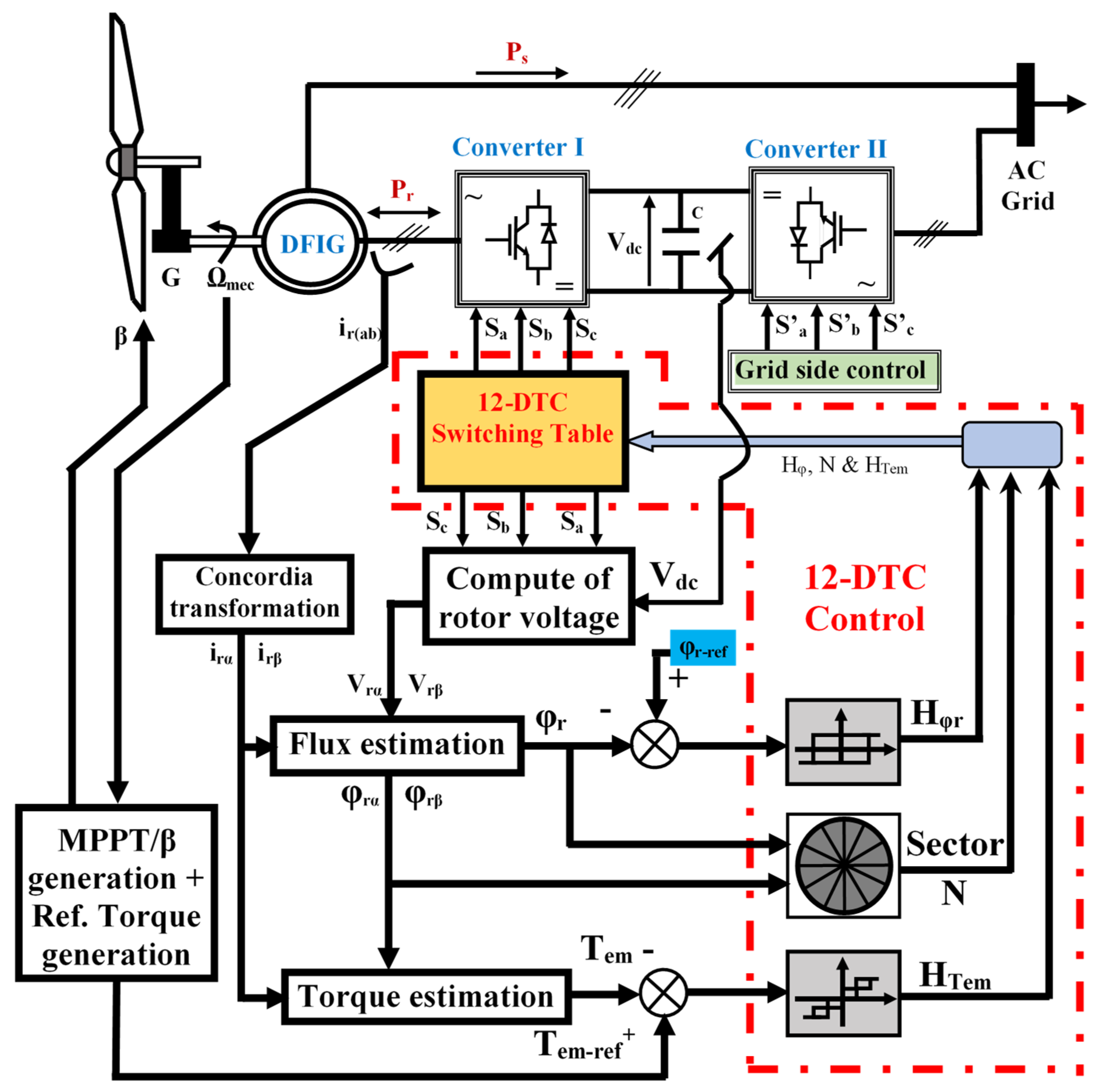
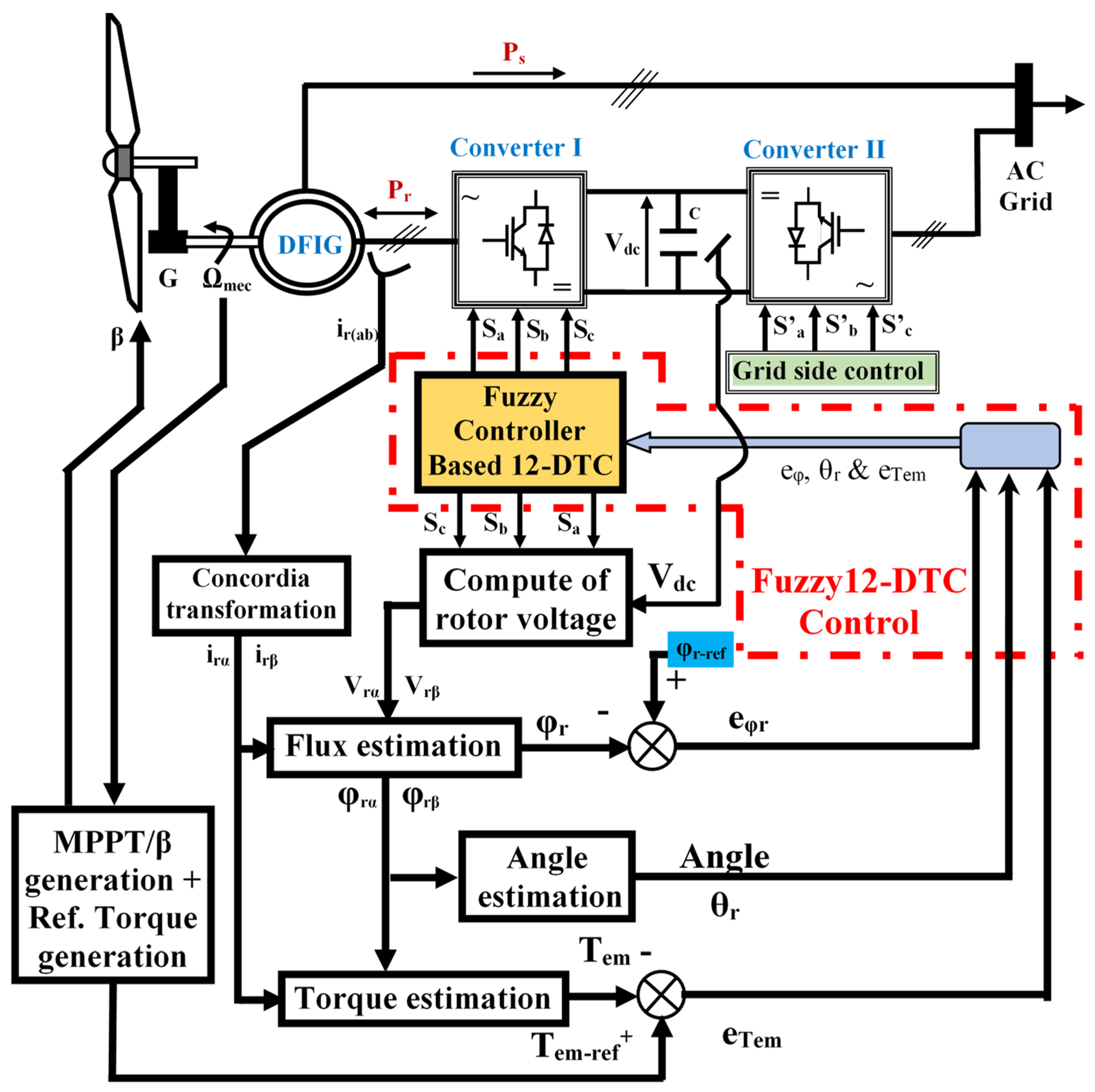
- A novel-control-strategy-based non-linear modified fuzzy 12-sector-DTC (F12-DTC) was applied to the rotor side of the DFIG driven by WT under random and wide ranges of the wind profile. The new F12-DTC is investigated to solve the problem of ripples under the three DFIG operation modes and the over-speed.
- The novel approach aims directly at the causes of ripples and generated current distortions, the hysteresis regulators, and the switching table, which were replaced by the fuzzy logic controller.
- The fuzzy controller was designed based on 12 sectors instead of 6 sectors, which extends the freedom degrees of the rotor voltage vector selection. The FC’s member numerical tests were used to modify functions and fuzzy rules, in order to overcome the WT-DFIG system’s constraints and drawbacks.
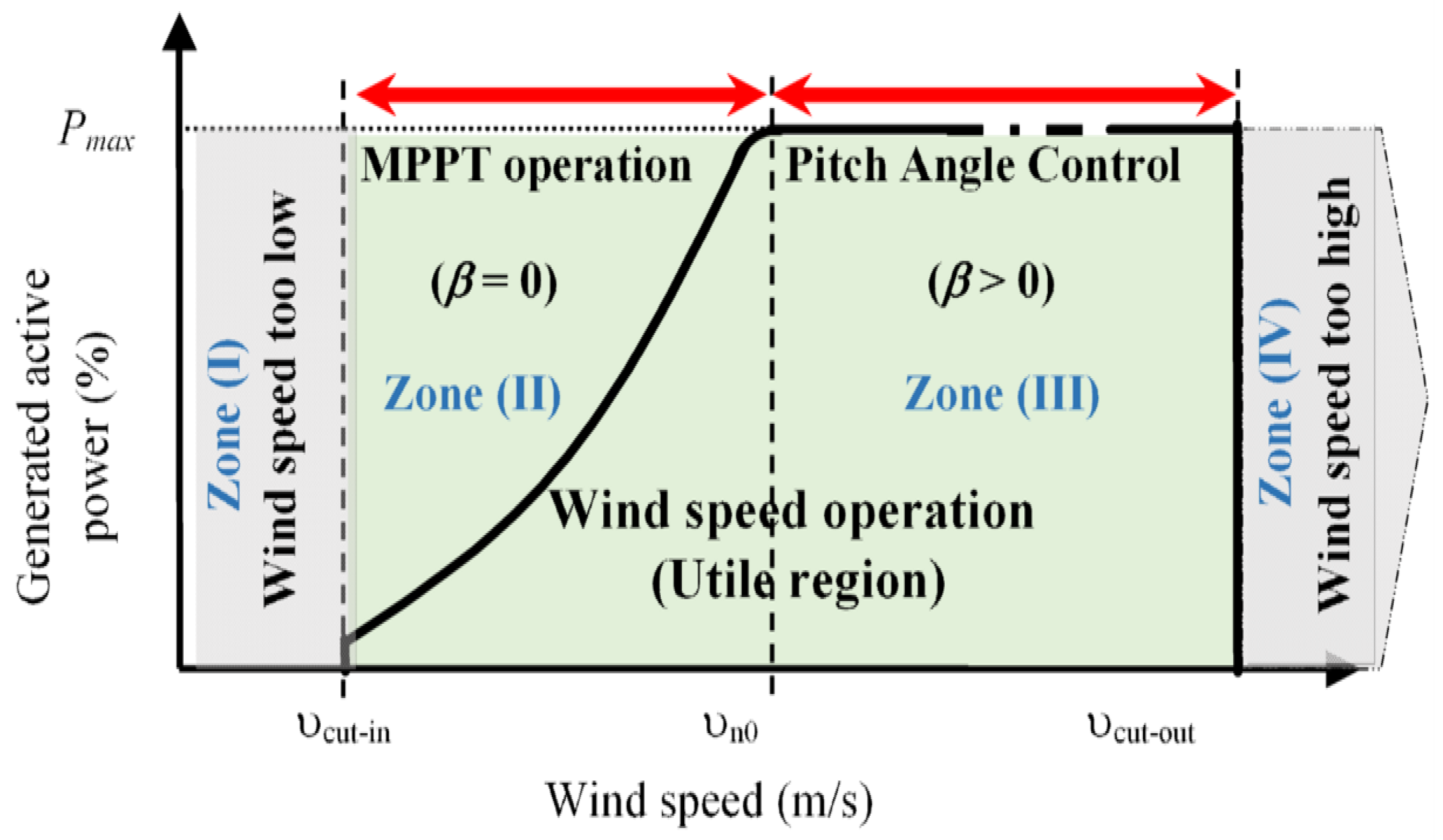
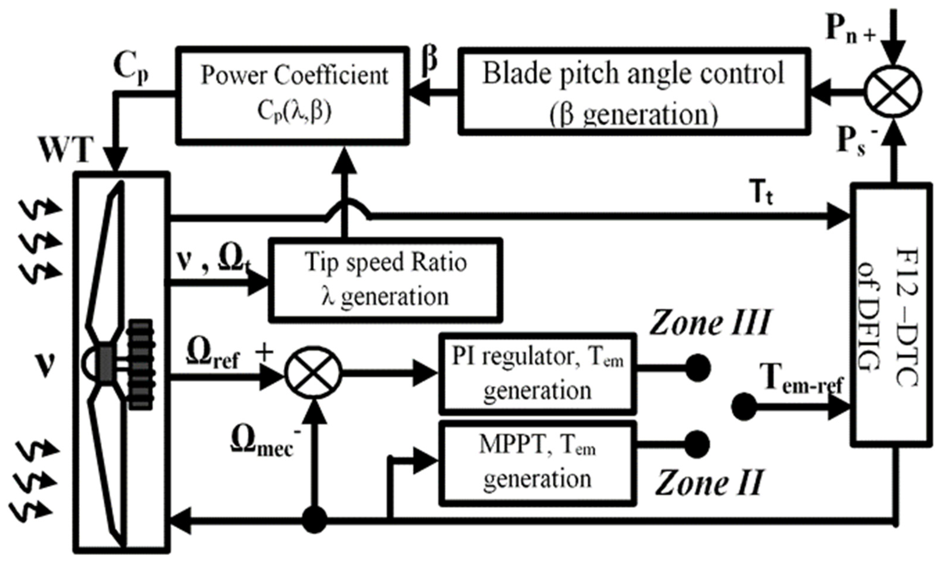
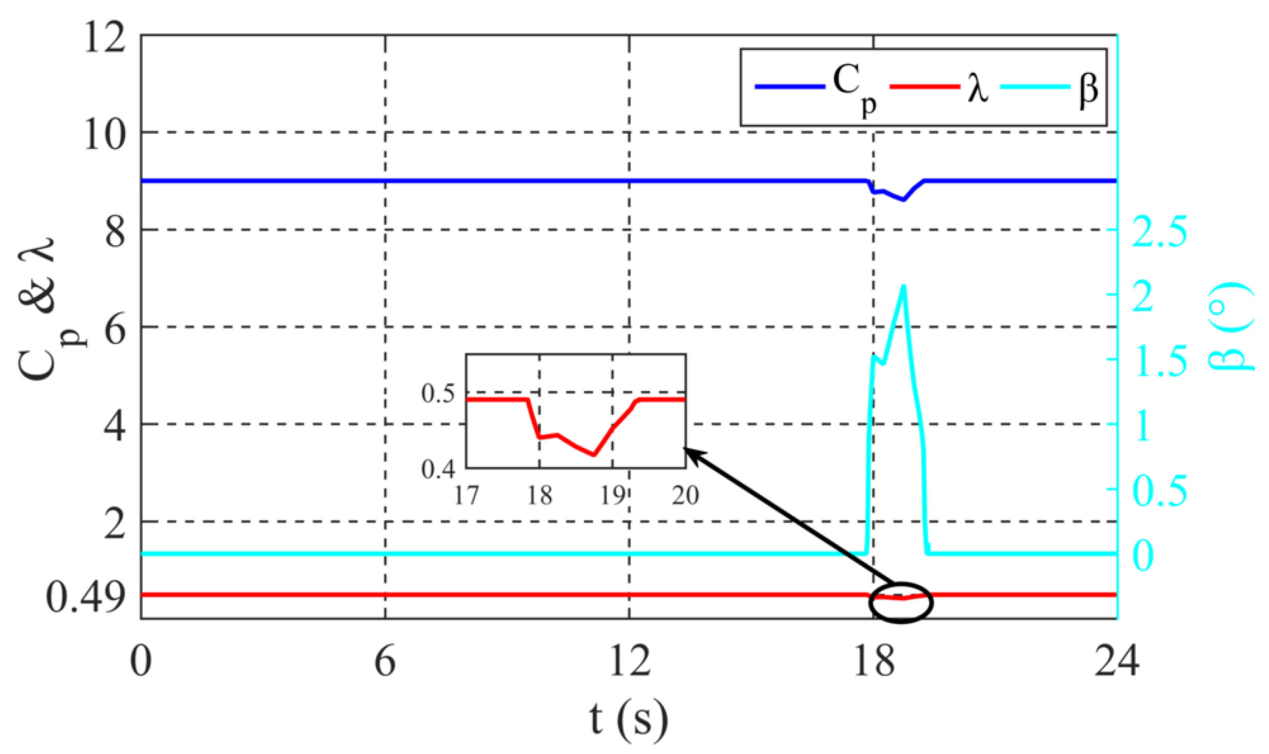
- The treatment of all operation modes of the DFIG (sub-synchronous, super-synchronous, synchronous modes, and the over-speed) operates in a successive and continuous way, where during sub, super, and synchronous operating modes, the power is optimized using the MPPT algorithm, and, during the over-speed, the power is limited at its value using the pitch angle control.
- A graphical and analytical comparison was made between the proposed F12-DTC and both C-DTC and 12-DTC in order to show the significant improvement in the proposed strategy.
2. Materials and Methods
2.1. Wind Turbine Model
2.2. The Working Zones of Wind Turbine System
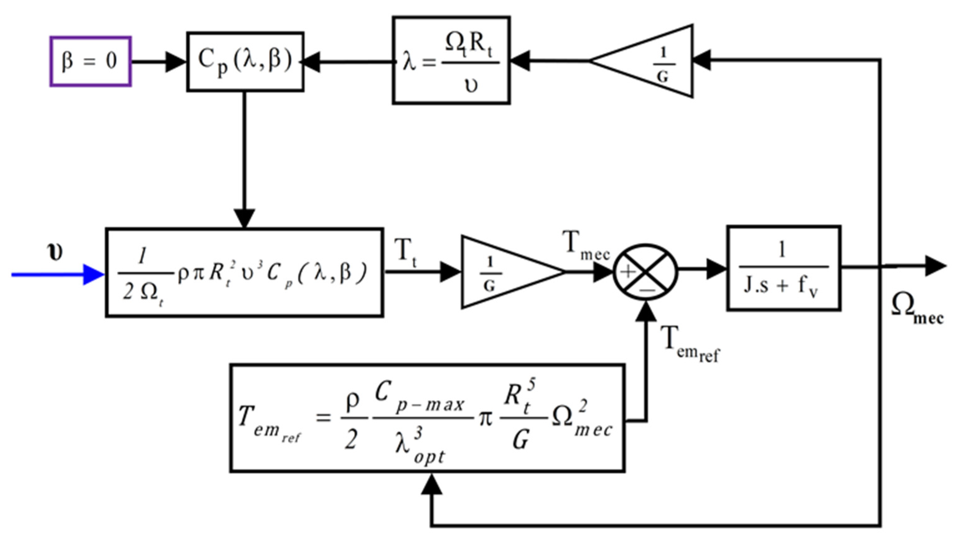
2.3. Maximum Power Point Tracking Algorithm
2.4. Pitch Angle Control
2.5. DFIG Modelling
3. Descriptions of the Treated Control Methods and the Proposed Strategy
3.1. Conventional Direct Torque Control Description
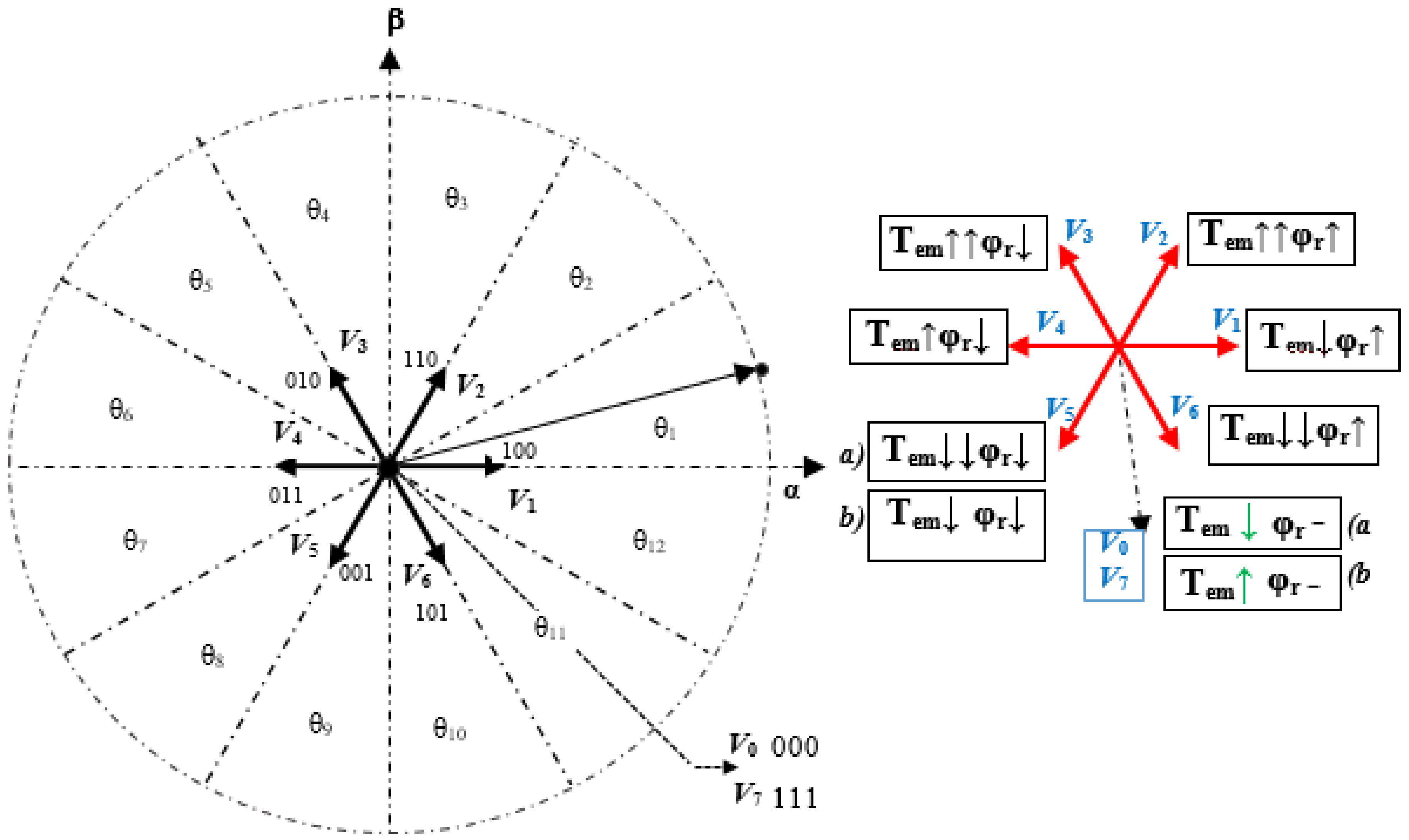
3.2. Direct-Torque-Control-Based Twelve Sectors Applied to WT-DFIG System
3.3. Proposed Controller Design Process of the Proposed F12-DTC
3.3.1. Fuzzification
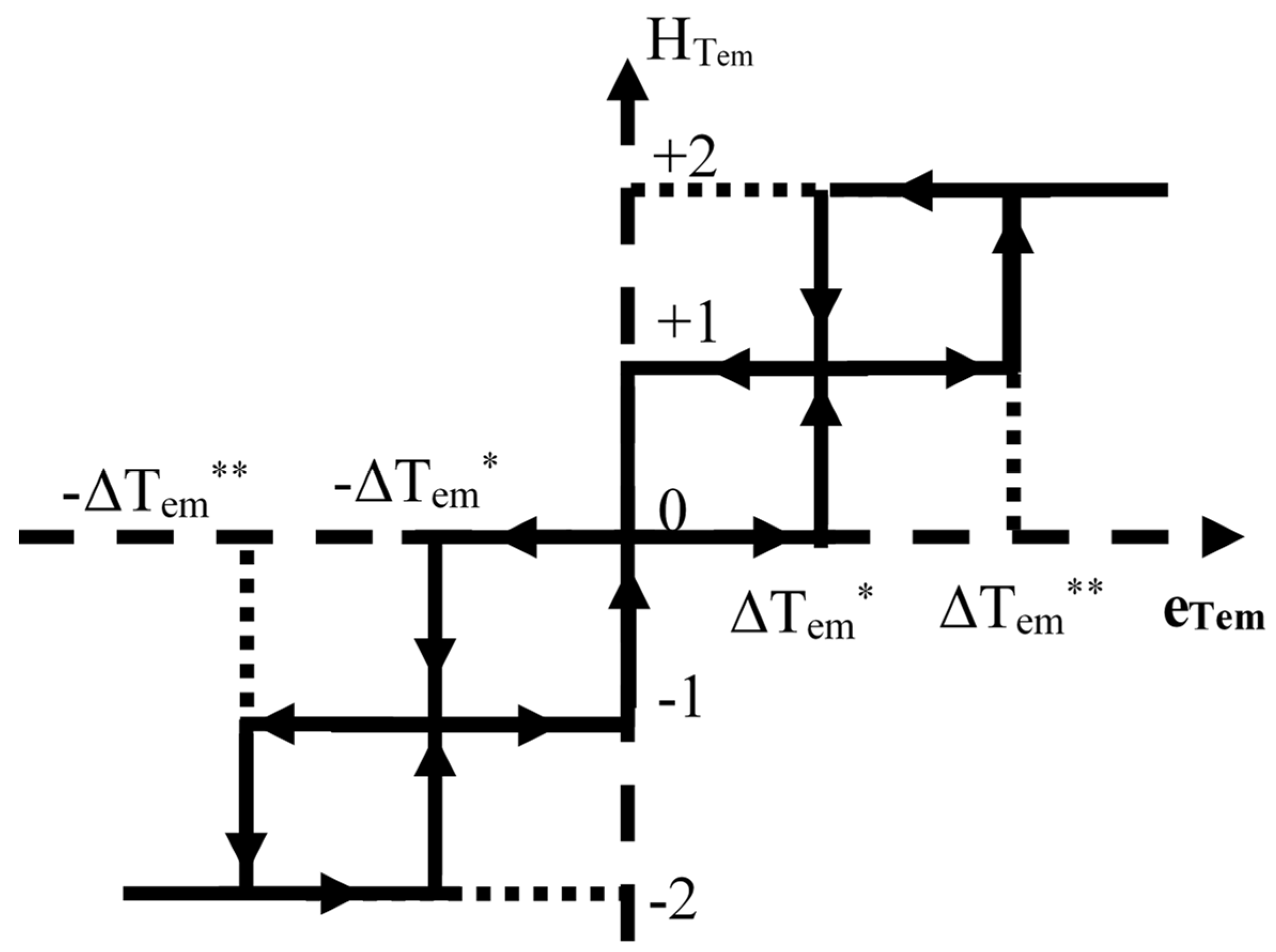
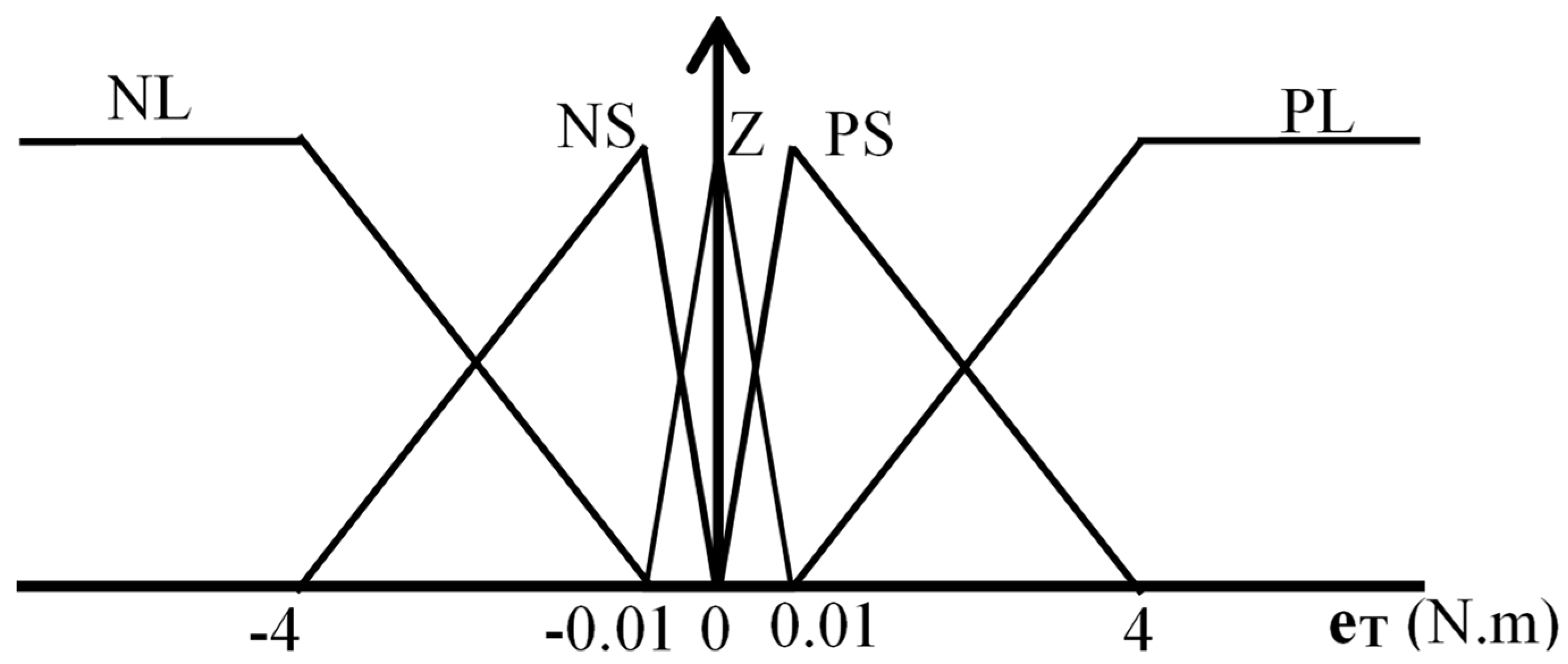
- MFs of torque error (eTem) are five linguistic variables: negative large (NL), positive large (PL), negative small (NS), positive small (PS), and zero (Z). The NL and PL are formed by trapezoidal MFs, and the NS, PS, and Z are formed by triangular MFs, as shown in Figure 8.
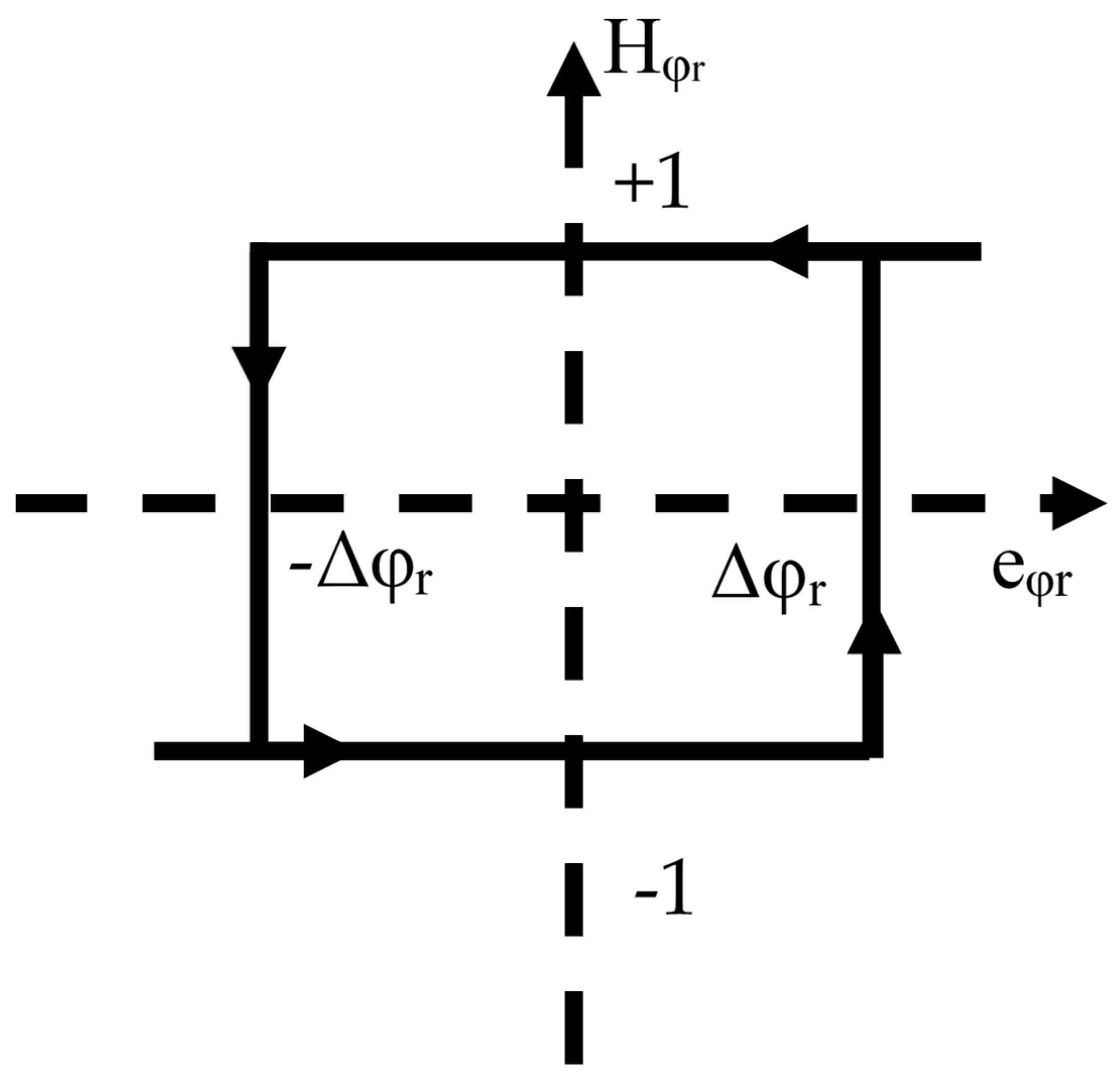
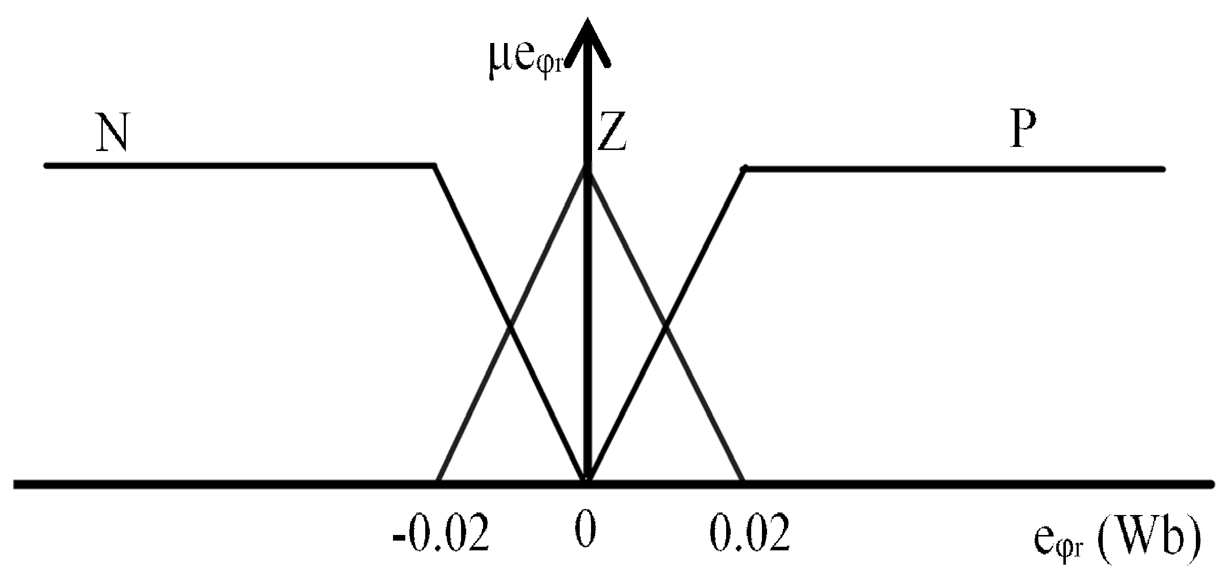
- MFs of flux error (eφr) are three linguistic variables: negative (N), positive (P), and zero (Z). N and P are formed by trapezoidal MFs, and Z is formed by triangular MFs, as shown in Figure 9.
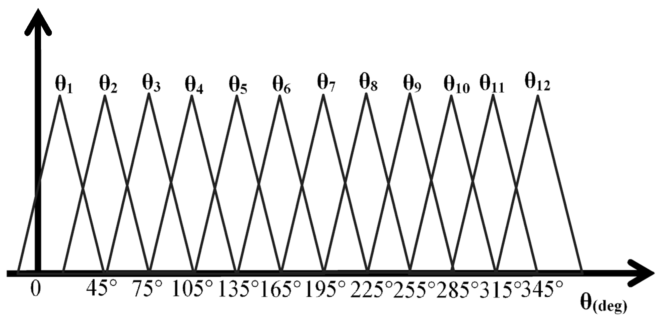
- MFs of the rotor flux angle are twelve linguistic variables: θ1, …, θ12; they are formed by triangular MFs, as illustrated in Figure 10.
3.3.2. Fuzzy Rules
3.3.3. Defuzzification
4. Simulation Results and Discussion
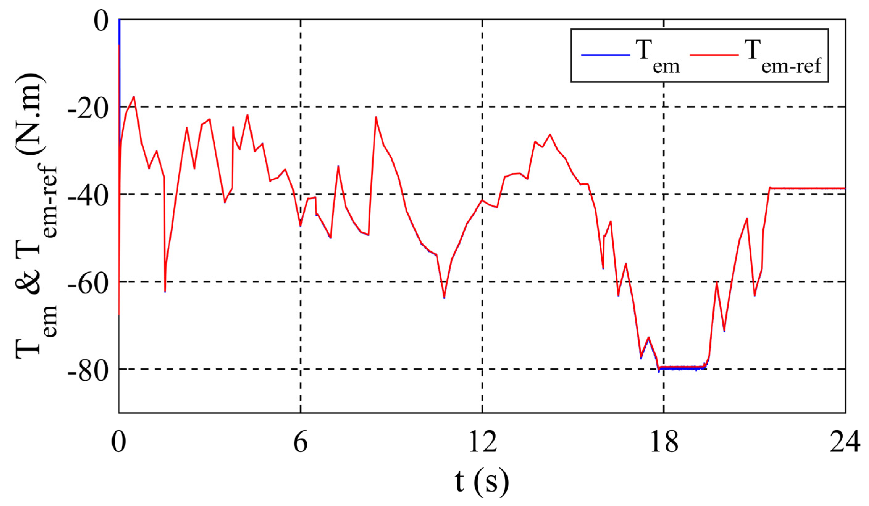
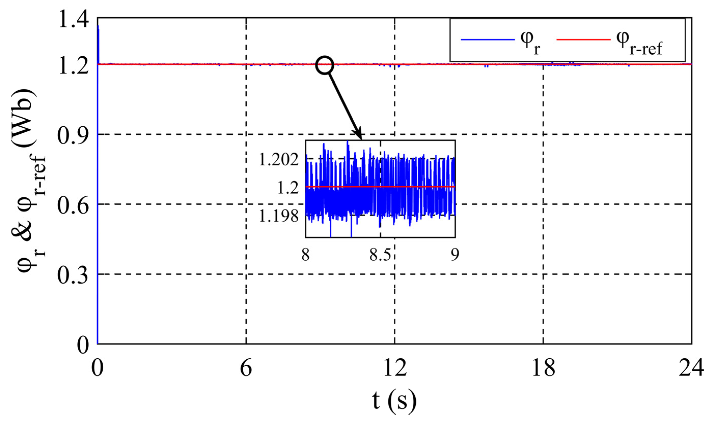
4.1. Robustness and Tracking Tests of References for a Random Profile of The Set-Points
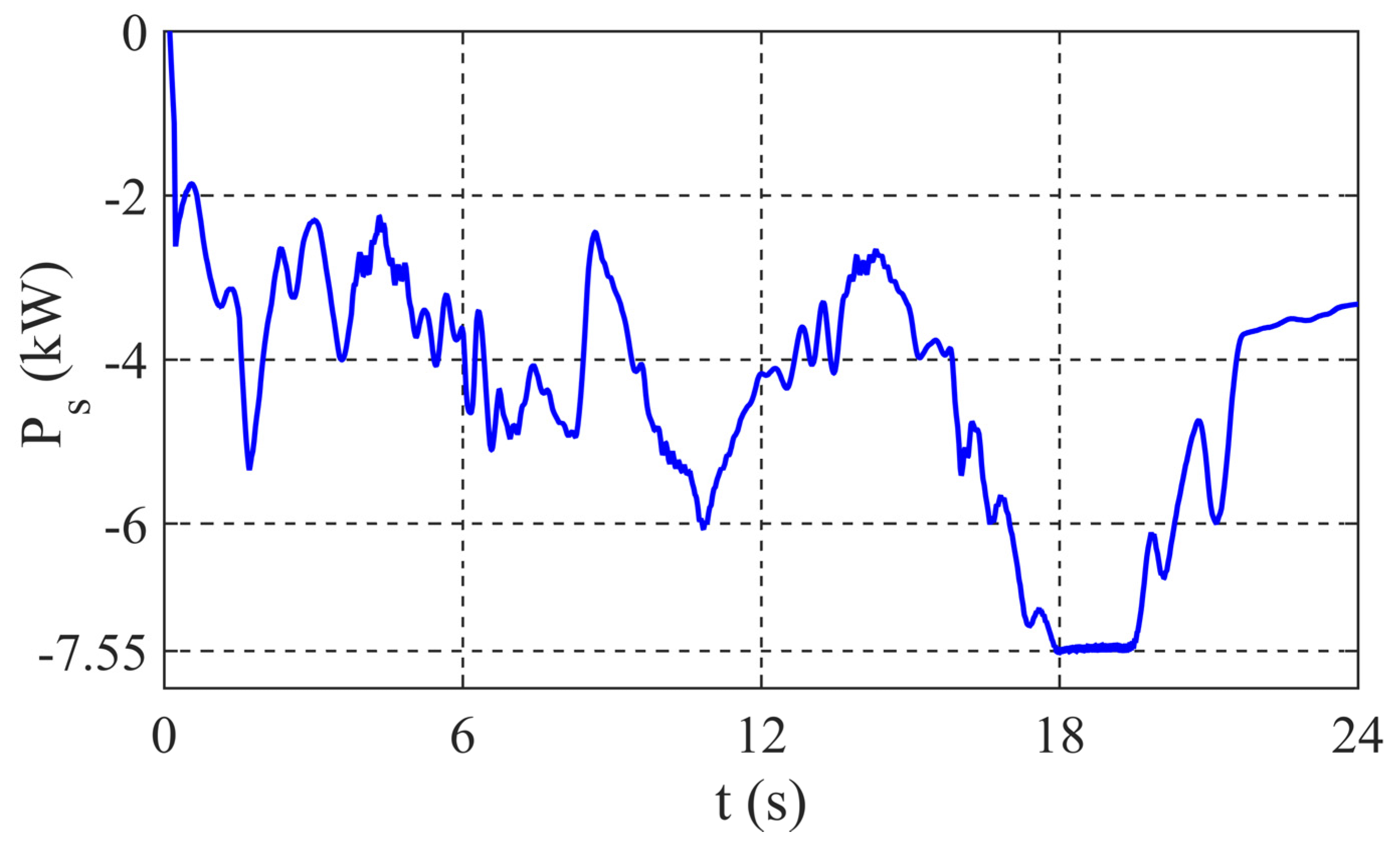
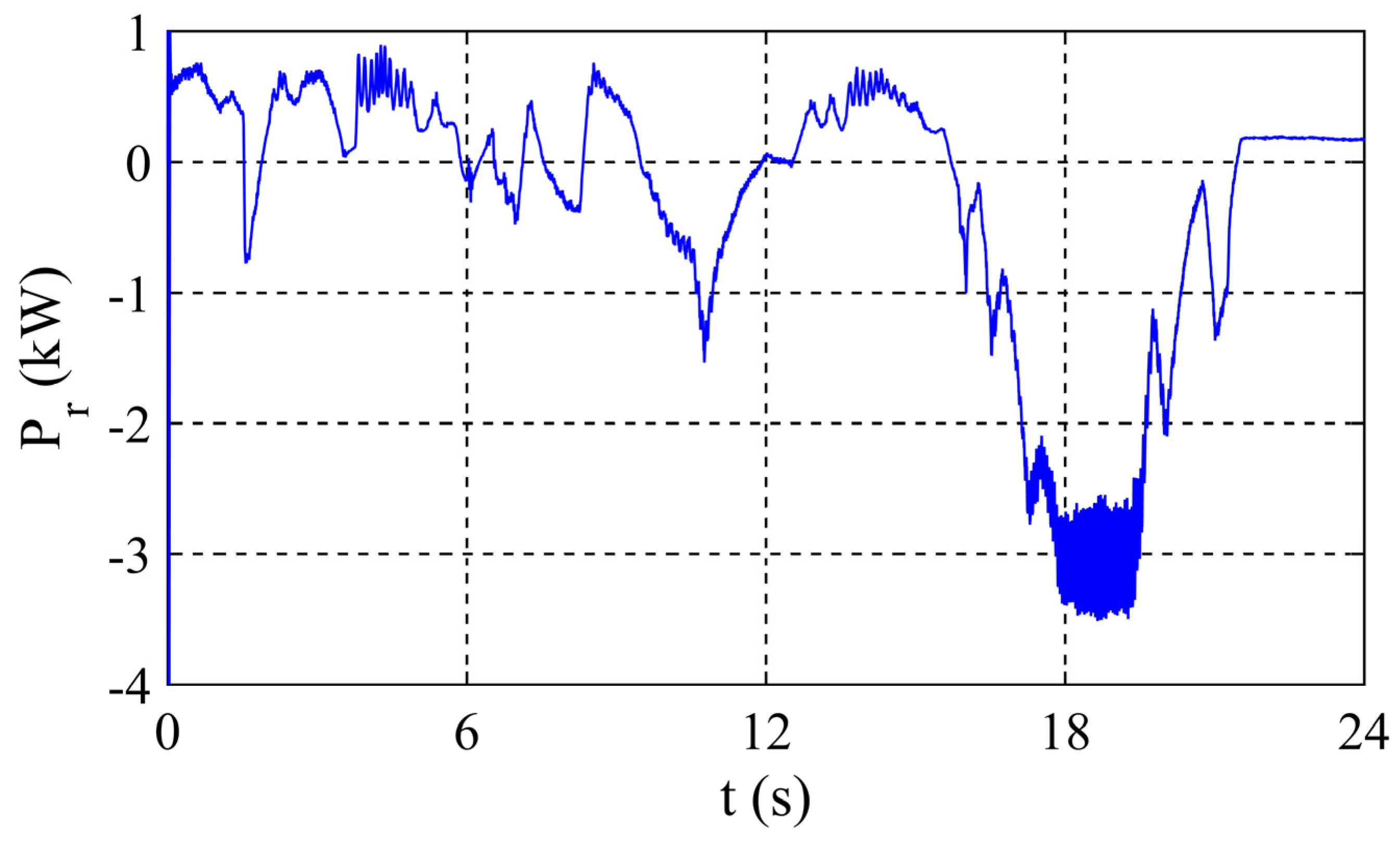
- The positive sign of the rotor active power indicates the sub-synchronous mode, where the DFIG absorbs energy from the AC-grid by its rotor.
- The synchronous mode is characterized by positive rotor active power, with a low value because it is dissipated in the rotor resistances.
- In the super-synchronous mode and the over-speed case, the rotor active power is characterized by a negative sign, where the rotor generates active power to the AC grid.
4.2. Obtained Results Summary with Comparison
5. Conclusions
Author Contributions
Funding
Institutional Review Board Statement
Informed Consent Statement
Data Availability Statement
Acknowledgments
Conflicts of Interest
Appendix A. The Matlab/Simulink Model Scheme of the Studied System with Explanations about the Implementation

References
- Barambones, O. Robust wind speed estimation and control of variable speed wind turbines. Asian J. Control. 2019, 21, 856–867. [Google Scholar] [CrossRef]
- Yang, J.; Fang, L.; Song, D.; Su, M.; Yang, X.; Huang, L.; Joo, Y.H. Review of control strategy of large horizontal-axis wind turbines yaw system. Wind. Energy 2021, 24, 97–115. [Google Scholar] [CrossRef]
- Sahri, Y.; Tamalouzt, S.; Hamoudi, F.; Belaid Lalouni, S.; Bajaj, M.; Alharthi, M.M.; Alzaidi, M.S.; Ghoneim, S.S.M. New intelligent direct power control of DFIG-based wind conversion system by using machine learning under variations of all operating and compensation modes. Energy Rep. 2021, 7, 6394–6412. [Google Scholar] [CrossRef]
- Nobela, O.N.; Bansal, R.C.; Justo, J.J. A review of power quality compatibility of wind energy conversion systems with the South African utility grid. Renew. Energy Focus 2019, 31, 63–72. [Google Scholar] [CrossRef]
- Sahri, Y.; Tamalouzt, S.; Belaid Lalouni, S. Enhanced Direct Power Control Strategy of a DFIG-Based Wind Energy Conversion System Operating Under Random Conditions. Period. Polytech. Electr. Eng. Comput. Sci. 2021, 65, 196–206. [Google Scholar] [CrossRef]
- Tamalouzt, S.; Idjdarene, K.; Rekioua, T.; Abdessemed, R. Direct Torque Control of Wind Turbine Driven Doubly Fed Induction Generator. Rev. Roum. Sci. Techn. Électrotechn. Énerg. 2016, 61, 244–249. [Google Scholar]
- Reza, C.; Islam, M.D.; Mekhilef, S. A review of reliable and energy efficient direct torque-controlled induction motor drives. Renew. Sustain. Energy Rev. 2014, 37, 919–932. [Google Scholar] [CrossRef]
- Abdelli, R.; Rekioua, D.; Rekioua, T.; Tounzi, A. Improved direct torque control of an induction generator used in a wind conversion system connected to the grid. ISA Trans. 2013, 52, 525–538. [Google Scholar] [CrossRef] [PubMed]
- Habetler, T.G.; Profumo, F.; Pastorelli, M.; Tolbert, L.M. Direct torque control of induction machines using space vector modulation. IEEE Trans. Ind. Appl. 1992, 28, 1045–1053. [Google Scholar] [CrossRef]
- Agha Kashkooli, M.R.; Madani, S.M.; Sadeghi, R. Improved direct torque control of DFIG with reduced torque and flux ripples at constant switching frequency. In Proceedings of the 2016 7th Power Electronics, Drive Systems and Technologies Conference (PEDSTC 2016), Tehran, Iran, 16–18 February 2016; pp. 58–63. [Google Scholar] [CrossRef]
- Wong, K.C.; Ho, S.L.; Cheng, K.W.E. Direct torque control of a doubly-fed induction generator with space vector modulation. Electr. Power Compon. Syst. 2008, 36, 1337–1350. [Google Scholar] [CrossRef]
- Payam, A.F.; Hashemnia, M.N.; Faiz, J. Robust DTC control of Doubly Fed Induction machines based on input-output feedback linearization using recurrent neural networks. J. Power Electron. 2011, 11, 719–725. [Google Scholar] [CrossRef] [Green Version]
- Boulouiha, H.M.; Allali, A.; Laouer, M.; Tahri, A.; Denaï, M.; Draou, A. Direct torque control of multilevel SVPWM inverter in variable speed SCIG-based wind energy conversion system. Renew. Energy 2015, 80, 140–152. [Google Scholar] [CrossRef]
- Song, D.; Chang, Q.; Zheng, S.; Yang, S.; Yang, J.; Joo, Y.H. Adaptive Model Predictive Control for Yaw System of Variable Speed Wind Turbines. J. Mod. Power Syst. Clean Energy 2021, 9, 219–224. [Google Scholar] [CrossRef]
- Kalamian, N.; Verij Kazemi, M.; Gholomian, S.A. Direct power control of DFIG by using nonlinear model predective controller. Asian J. Control. 2016, 18, 985–999. [Google Scholar] [CrossRef]
- Mokhtari, M.; Davari, S.A. Predictive torque control of DFIG with torque ripple reduction. In Proceedings of the 2016 IEEE International Conference on Power and Energy (PECon), Melaka, Malaysia, 28–29 November 2016; pp. 763–768. [Google Scholar] [CrossRef]
- Zhang, Y.; Li, Z.; Wang, T.; Hu, J.; Zhu, J. Predictive direct torque and flux control of doubly fed induction generator with switching frequency reduction for wind energy applications. In Proceedings of the 2011 International Conference on Electrical Machines and Systems, Beijing, China, 20–23 August 2011; pp. 1–6. [Google Scholar] [CrossRef]
- Abad, G.; Rodríguez, M.A.; Poza, J. Two-level VSC based predictive direct torque control of the doubly fed induction machine with reduced torque and flux ripples at low constant switching frequency. IEEE Trans. Power Electron. 2008, 23, 1050–1061. [Google Scholar] [CrossRef]
- Bourouina, A.; Djahbar, A.; Chaker, A.; Boudjema, Z. High order sliding mode direct torque control of a DFIG supplied by a five-level SVPWM inverter for the wind turbine. Elektrotehniski Vestn. 2018, 85, 263–270. [Google Scholar]
- Boudjem, Z.; Taleb, R.; Djeriri, Y.; Yahdou, A. A novel direct torque control using second order continuous sliding mode of a doubly fed induction generator for a wind energy conversion system. Turk. J. Elec. Eng. Comput. Sci. 2017, 25, 965–975. [Google Scholar] [CrossRef] [Green Version]
- Tamalouzt, S.; Belkhier, Y.; Sahri, Y.; Bajaj, M.; Ullah, N.; Chowdhury, M.S.; Titseesang, T.; Techato, K. Enhanced Direct Reactive Power Control-Based Multi-Level Inverter for DFIG Wind System under Variable Speeds. Sustainability 2021, 13, 9060. [Google Scholar] [CrossRef]
- Moualdia, A.; Boudana, D.; Bouchhida, O.; Wira, P. Direct Torque control based multi-level inverter and artificial neural networks of wind energy conversion system. In Proceedings of the 2016 8th International Conference on Modelling, Identification and Control (ICMIC), Algiers, Algeria, 15–17 November 2016. [Google Scholar] [CrossRef]
- Al-Quteimat, A.; Roccaforte, A.; Schäfer, U. Performance improvement of Direct Torque Control for Doubly Fed Induction Generator with 12 Sector Methodology. In Proceedings of the 5th International Conference on Renewable Energy Research and Application, Birmingham, UK, 20–23 November 2016. [Google Scholar] [CrossRef]
- Taleb, M.; El Haroussi, M.; Ba-Razzouk, A. Improved Direct Torque Control of a Douby Fed Induction Generator in a Wind Energy Conversion System. In Proceedings of the 6th International Renewable and Sustainable Energy Conference (IRSEC), Rabat, Morocco, 5–8 December 2018. [Google Scholar] [CrossRef]
- Benbouhenni, H. Five-level DTC with 12 sectors of induction motor drive using neural networks controller for low torque ripple. Acta Electrotech. Inform. 2018, 18, 61–66. [Google Scholar] [CrossRef]
- Kim, S.J.; Park, J.; Lee, D.H. A Predictive DTC-PWM using 12 Vectors for Permanent Magnet Synchronous Motor. In Proceedings of the 2019 10th International Conference on Power Electronics and ECCE Asia (ICPE 2019-ECCE Asia), Busan, Korea, 27–30 May 2019. [Google Scholar] [CrossRef]
- Manuprasad, P.; Mohanty, K.B. Implementation of 12 Sector Fuzzy Controller for Direct Torque Control of Induction Motor. In Proceedings of the 2019 Innovations in Power and Advanced Computing Technologies (i-PACT), Vellore, India, 22–23 March 2019. [Google Scholar] [CrossRef]
- Djeriri, Y.; Meroufel, A.; Massoum, A. Artificial neural network based direct torque control of doubly fed induction generator. J. Electr. Eng. 2014, 14, 71–79. [Google Scholar]
- El Ouanjli, N.; Motahhir, S.; Derouich, A.; El Ghzizal, A.; Taoussi, M.; Chebabhi, A. Improved DTC strategy of doubly fed induction motor using fuzzy logic controller. Energy Rep. 2019, 5, 271–279. [Google Scholar] [CrossRef]
- Ayrir, W.; Ourahou, M.; El Hassouni, B.; Haddi, A. Direct torque control improvement of a variable speed DFIG based on a fuzzy inference system. Math Comput. Simul. 2018, 167, 308–324. [Google Scholar] [CrossRef]
- Ayrir, W.; Haddi, A. Fuzzy 12 sectors improved direct torque control of a DFIG with stator power factor control strategy. Int. Trans. Electr. Energy Syst. 2019, 29, e12092. [Google Scholar] [CrossRef]
- Li, S.; Timothy AHaskew Yang-Ki, H.; Shukul, M. Integrating electrical and aerodynamic characteristics for DFIG wind energy extraction and control study. Int. J. Energy Res. 2010, 34, 1052–1070. [Google Scholar] [CrossRef]
- Sahri, Y.; Tamalouzt, S.; Belaid Lalaouni, S. Direct Torque Control of DFIG Driven by Wind Turbine System Connected to the Grid. In Proceedings of the 2018 International Conference on Wind Energy and Applications in Algeria (ICWEAA), Algiers, Algeria, 6–7 November 2018. [Google Scholar] [CrossRef]
- Lalouni, S.; Rekioua, D.; Idjdarene, K.; Tounzi, A. Maximum Power Point Tracking Based Hybrid Hill-climb Search Method Applied to Wind Energy Conversion System. Electr. Power Compon. Syst. 2015, 43, 1028–1038. [Google Scholar] [CrossRef]
- Shaikh Mo, S.A.; Maurya, R.; Gupta, N. Modified Switching Table-Based Direct Torque Control of Six-Phase Induction Motor Drive. Electr. Power Compon. Syst. 2019, 47, 1077–1089. [Google Scholar] [CrossRef]
- Tamalouzt, S.; Benyahia, N.; Rekioua, T.; Rekioua, D.; Abdessemed, R. Performances analysis of WT-DFIG with PV and fuel cell hybrid power sources system associated with hydrogen storage hybrid energy system. Int. J. Hydrogen Energy 2016, 41, 21006–21021. [Google Scholar] [CrossRef]
- Sahri, Y.; Belkhier, Y.; Tamalouzt, S.; Ullah, N.; Shaw, R.N.; Chowdhury, M.S.; Techato, K. Energy Management System for Hybrid PV/Wind/Battery/Fuel Cell in Microgrid-Based Hydrogen and Economical Hybrid Battery/Super Capacitor Energy Storage. Energies 2021, 14, 5722. [Google Scholar] [CrossRef]


| Hφr | HTem | N | |||||
|---|---|---|---|---|---|---|---|
| 1 | 2 | 3 | 4 | 5 | 6 | ||
| −1 | −1 | V5 | V6 | V1 | V2 | V3 | V4 |
| 0 | V7 | V0 | V7 | V0 | V7 | V0 | |
| +1 | V3 | V4 | V5 | V6 | V1 | V2 | |
| +1 | −1 | V6 | V1 | V2 | V3 | V4 | V5 |
| 0 | V0 | V7 | V0 | V7 | V0 | V7 | |
| +1 | V2 | V3 | V4 | V5 | V6 | V1 | |
| Sector N | θ1 | θ2 | θ3 | θ4 | θ5 | θ6 | θ7 | θ8 | θ9 | θ10 | θ11 | θ12 | |
|---|---|---|---|---|---|---|---|---|---|---|---|---|---|
| Hφr | HTem | ||||||||||||
| 1 | 2 | V2 | V3 | V3 | V4 | V4 | V5 | V5 | V6 | V6 | V1 | V1 | V2 |
| 1 | V2 | V2 | V3 | V3 | V4 | V4 | V5 | V5 | V6 | V6 | V1 | V1 | |
| 0 | V0 | V7 | V7 | V0 | V0 | V7 | V7 | V0 | V0 | V7 | V7 | V0 | |
| −1 | V1 | V1 | V2 | V2 | V3 | V3 | V4 | V4 | V5 | V5 | V6 | V6 | |
| −2 | V6 | V1 | V1 | V2 | V2 | V3 | V3 | V4 | V4 | V5 | V5 | V6 | |
| −1 | 2 | V3 | V4 | V4 | V5 | V5 | V6 | V6 | V1 | V1 | V2 | V2 | V3 |
| 1 | V4 | V4 | V5 | V5 | V6 | V6 | V1 | V1 | V2 | V2 | V3 | V4 | |
| 0 | V7 | V0 | V0 | V7 | V7 | V0 | V0 | V7 | V7 | V0 | V0 | V7 | |
| −1 | V7 | V5 | V0 | V6 | V7 | V1 | V0 | V2 | V7 | V3 | V0 | V4 | |
| −2 | V5 | V6 | V6 | V1 | V1 | V2 | V2 | V3 | V3 | V4 | V4 | V5 | |
| eφr | eTem | Sectors | |||||||||||
|---|---|---|---|---|---|---|---|---|---|---|---|---|---|
| θ1 | θ2 | θ3 | θ4 | θ5 | θ6 | θ7 | θ8 | θ9 | θ10 | θ11 | θ12 | ||
| N | NL | V5 | V6 | V6 | V1 | V1 | V2 | V2 | V3 | V3 | V4 | V4 | V5 |
| NS | V5 | V5 | V6 | V6 | V1 | V1 | V2 | V2 | V3 | V3 | V4 | V4 | |
| Z | V0 | V7 | V7 | V0 | V0 | V7 | V7 | V0 | V0 | V7 | V7 | V0 | |
| PS | V3 | V4 | V4 | V5 | V5 | V6 | V6 | V1 | V1 | V2 | V2 | V3 | |
| PL | V3 | V3 | V4 | V4 | V5 | V5 | V6 | V6 | V1 | V1 | V2 | V2 | |
| Z | NL | V5 | V6 | V6 | V1 | V1 | V2 | V2 | V3 | V3 | V4 | V4 | V5 |
| NS | V0 | V0 | V7 | V7 | V0 | V0 | V7 | V7 | V0 | V0 | V7 | V7 | |
| Z | V0 | V0 | V7 | V7 | V0 | V0 | V7 | V7 | V0 | V0 | V7 | V7 | |
| PS | V3 | V3 | V4 | V4 | V5 | V5 | V6 | V6 | V1 | V1 | V2 | V2 | |
| PL | V2 | V3 | V3 | V4 | V4 | V5 | V5 | V6 | V6 | V1 | V1 | V2 | |
| P | NL | V6 | V1 | V1 | V2 | V2 | V3 | V3 | V4 | V4 | V5 | V5 | V6 |
| NS | V6 | V1 | V1 | V2 | V2 | V3 | V3 | V4 | V4 | V5 | V5 | V6 | |
| Z | V7 | V7 | V0 | V0 | V7 | V7 | V0 | V0 | V7 | V7 | V0 | V0 | |
| PS | V2 | V2 | V3 | V3 | V4 | V4 | V5 | V5 | V6 | V6 | V1 | V1 | |
| PL | V2 | V2 | V3 | V3 | V4 | V4 | V5 | V5 | V6 | V6 | V1 | V1 | |
| Parameter | Value | Parameter | Value |
|---|---|---|---|
| Rated Power (kW) | 7.5 | Vdc (V) | 880 |
| Frequency (Hz) | 50 | Rs (Ω) | 1.02 |
| Pole (pairs) | 3 | Rr (Ω) | 0.8 |
| Rt (m) | 3.24 | M (H) | 0.0664 |
| G | 5.065 | Ls (H) | 0.093 |
| ρ (kg/m3) | 1.1225 | Lr (H) | 0.081 |
| Performances | Operation Modes | Average | ||||
|---|---|---|---|---|---|---|
| Sub-Synchronous | Super-Synchronous | Synchronous | Over-Speed | |||
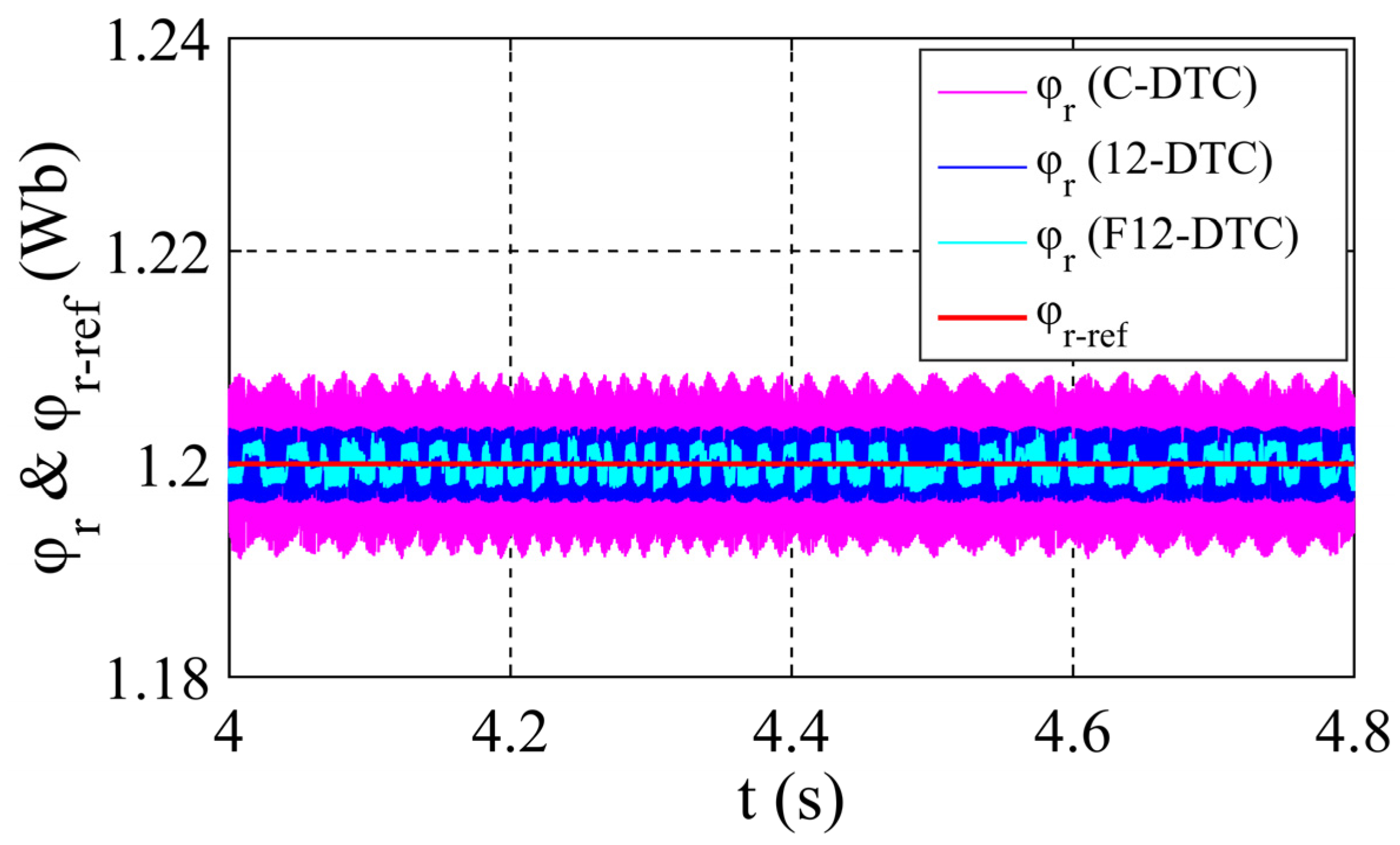
| φr(Wb) | C-DTC | 1.2000 ± 0.0088 | 1.2000 ± 0.0088 | 1.2000 ± 0.008 | 1.2000 ± 0.0084 | 1.2000 ± 0.0085 |
| 12-DTC | 1.2000 ± 0.0034 | 1.2000 ± 0.0060 | 1.2000 ± 0.007 | 1.2000 ± 0.0032 | 1.2000 ± 0.0049 | |
| F12-DTC | 1.2000 ± 0.0020 | 1.2000 ± 0.0034 | 1.2000 ± 0.007 | 1.2000 ± 0.0020 | 1.2000 ± 0.0036 | |
| Ripple reduction rate of F12-DTC compared to C-DTC | 77.27% | 61.36% | 12.5% | 76.19% | 56.83% | |
| Ripple reduction rate of F12-DTC compared to 12-DTC | 41.17% | 43.33% | 0.00% | 37.5% | 30.5% | |
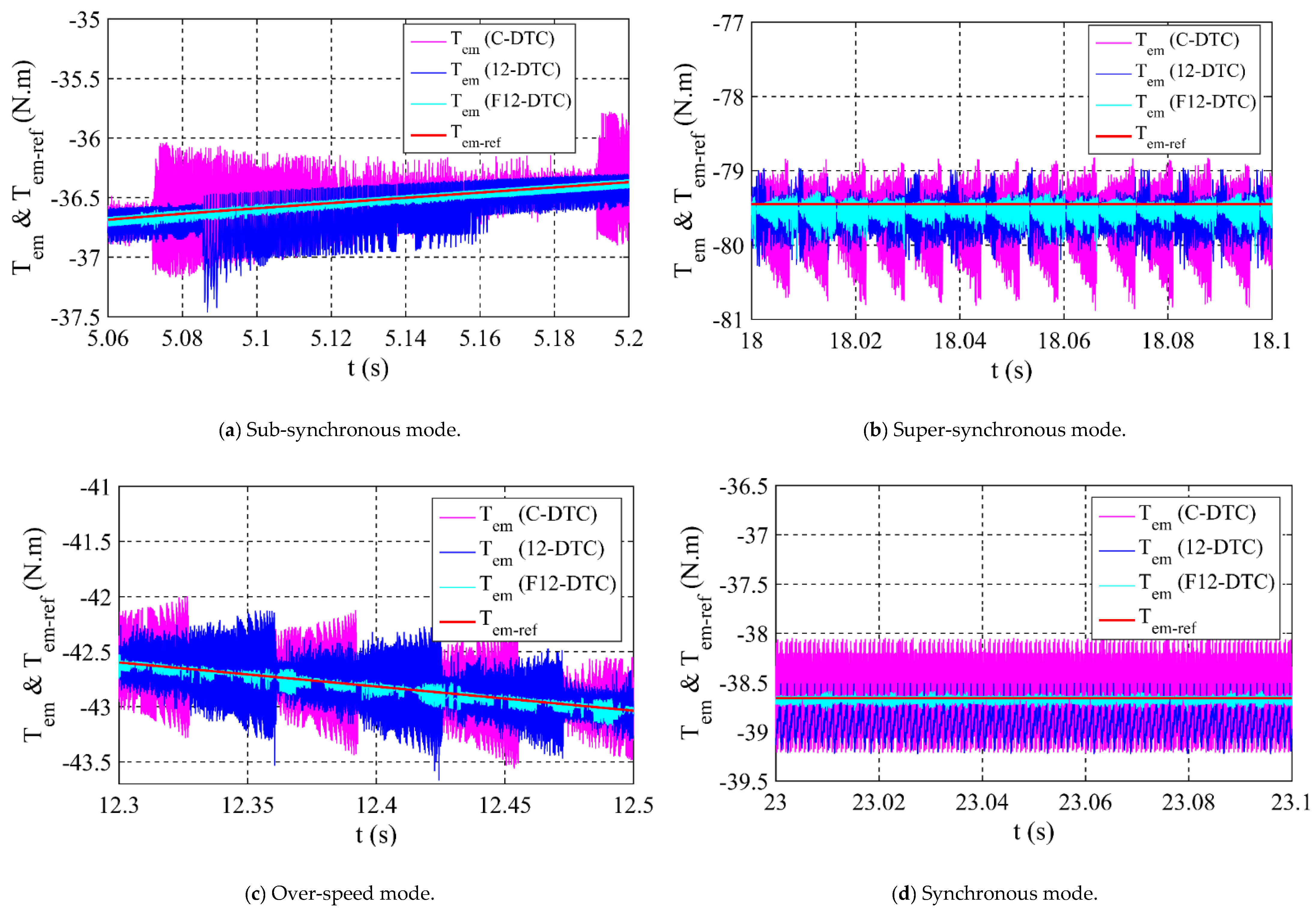
| Tem(N.m) | C-DTC | −36.65 ± 0.58 | −42.63 ± 0.64 | −38.66 ± 0.54 | −79.45 ± 1.33 | Tem ± 0.77 |
| 12-DTC | −36.65 ± 0.46 | −42.63 ± 0.52 | −38.66 ± 0.54 | −79.45 ± 0.66 | Tem ± 0.54 | |
| F12-DTC | −36.65 ± 0.09 | −42.63 ± 0.09 | −38.66 ± 0.09 | −79.45 ± 0.40 | Tem ± 0.16 | |
| Ripple reduction rate of F12-DTC compared to C-DTC | 84.48% | 85.93% | 83.00% | 69.92% | 80.83% | |
| Ripple reduction rate of F12-DTC compared to 12-DTC | 80.43% | 82.69% | 83.00% | 39.39% | 71.37% | |
Publisher’s Note: MDPI stays neutral with regard to jurisdictional claims in published maps and institutional affiliations. |
© 2021 by the authors. Licensee MDPI, Basel, Switzerland. This article is an open access article distributed under the terms and conditions of the Creative Commons Attribution (CC BY) license (https://creativecommons.org/licenses/by/4.0/).
Share and Cite
Sahri, Y.; Tamalouzt, S.; Lalouni Belaid, S.; Bacha, S.; Ullah, N.; Ahamdi, A.A.A.; Alzaed, A.N. Advanced Fuzzy 12 DTC Control of Doubly Fed Induction Generator for Optimal Power Extraction in Wind Turbine System under Random Wind Conditions. Sustainability 2021, 13, 11593. https://0-doi-org.brum.beds.ac.uk/10.3390/su132111593
Sahri Y, Tamalouzt S, Lalouni Belaid S, Bacha S, Ullah N, Ahamdi AAA, Alzaed AN. Advanced Fuzzy 12 DTC Control of Doubly Fed Induction Generator for Optimal Power Extraction in Wind Turbine System under Random Wind Conditions. Sustainability. 2021; 13(21):11593. https://0-doi-org.brum.beds.ac.uk/10.3390/su132111593
Chicago/Turabian StyleSahri, Younes, Salah Tamalouzt, Sofia Lalouni Belaid, Seddik Bacha, Nasim Ullah, Ahmad Aziz Al Ahamdi, and Ali Nasser Alzaed. 2021. "Advanced Fuzzy 12 DTC Control of Doubly Fed Induction Generator for Optimal Power Extraction in Wind Turbine System under Random Wind Conditions" Sustainability 13, no. 21: 11593. https://0-doi-org.brum.beds.ac.uk/10.3390/su132111593