
Free Discharge of Subsurface Drainage Effluent: An Alternate Design of the Surface Drain System in Pakistan

 ,
,  ,
,  , , , , and
Abstract
:1. Introduction
2. Data and Methods
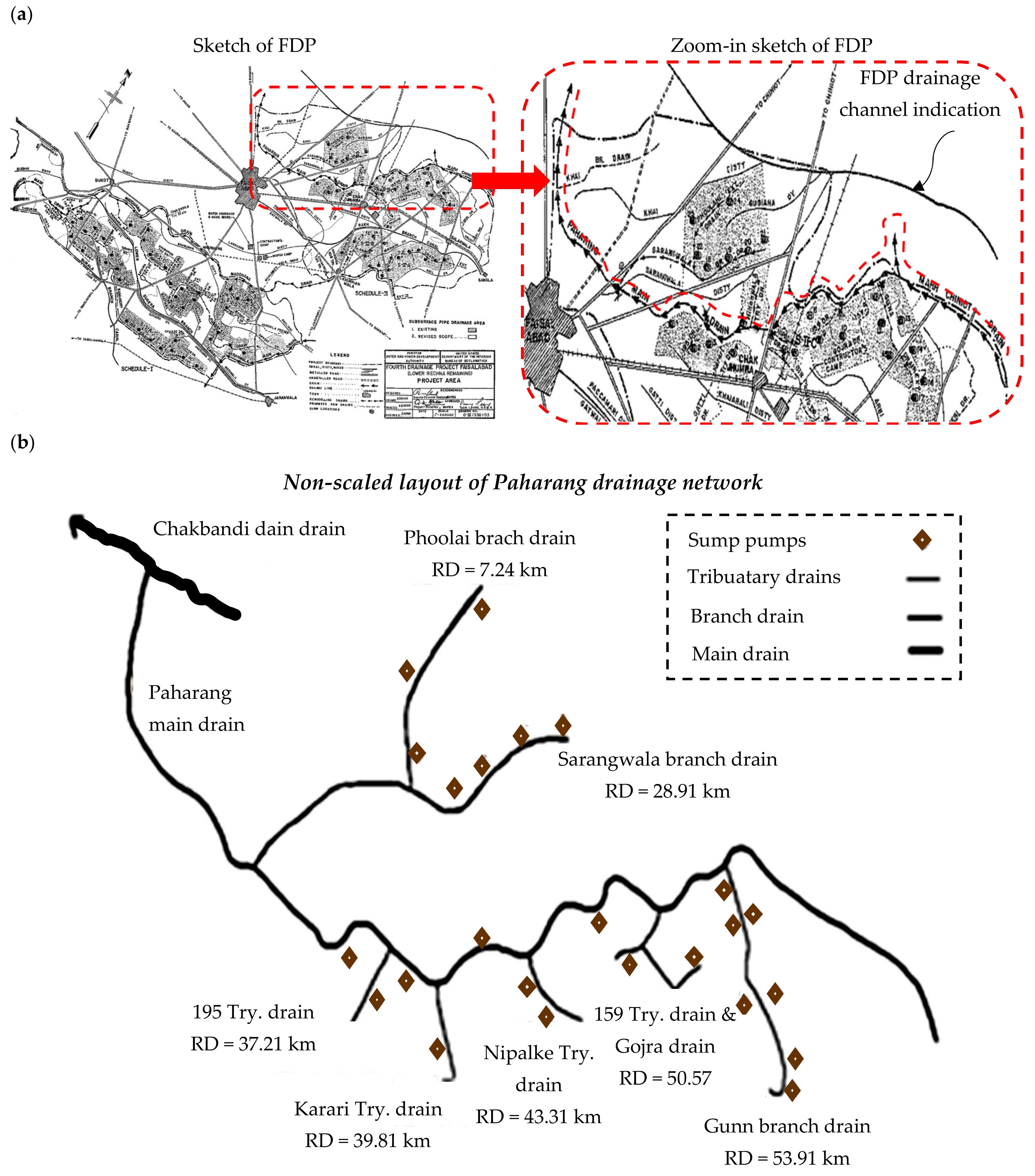
2.1. Study Area
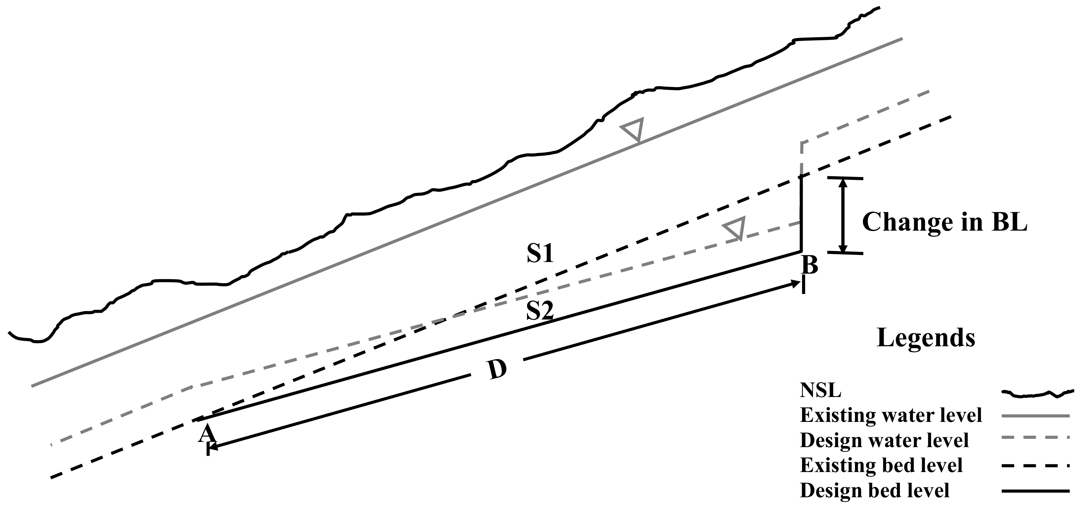
2.2. Computation of Required Bed Level
2.3. Redesign of Surface Drain L-Section
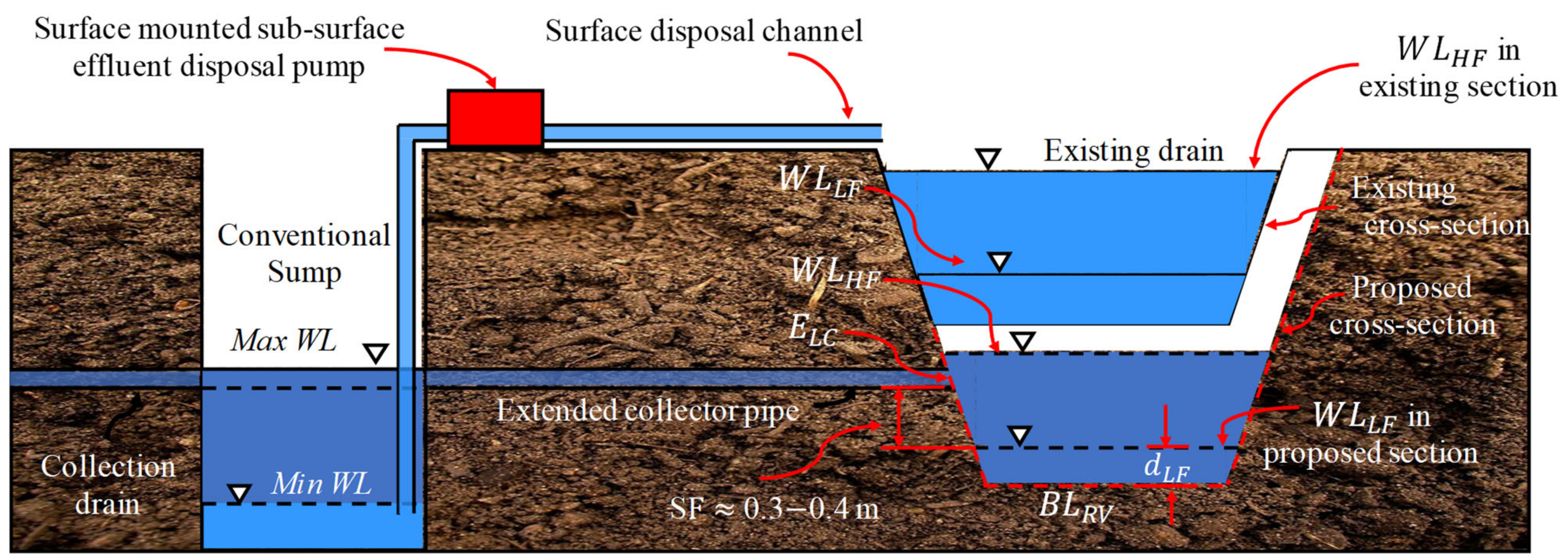
2.4. Flow Section Design
2.5. Flow Section Design
3. Results and Discussion
3.1. Required Bed Lowering and Design Continuity
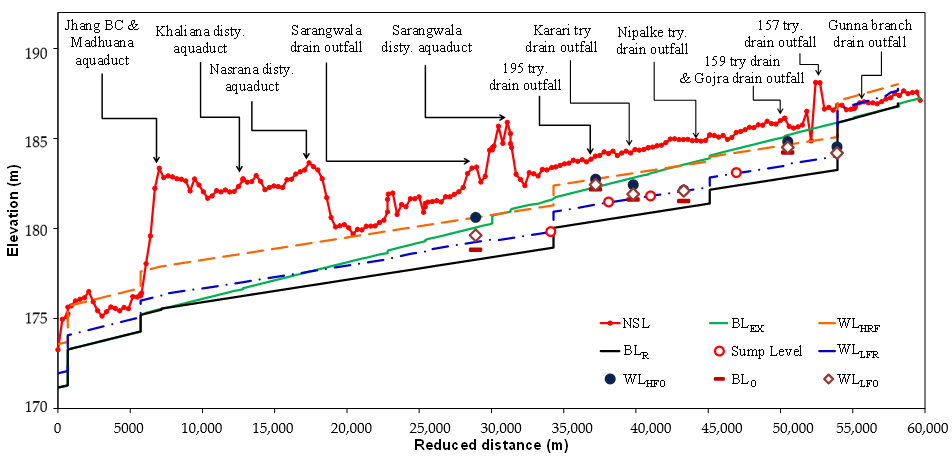
3.2. Redesigned Longitudinal Sections
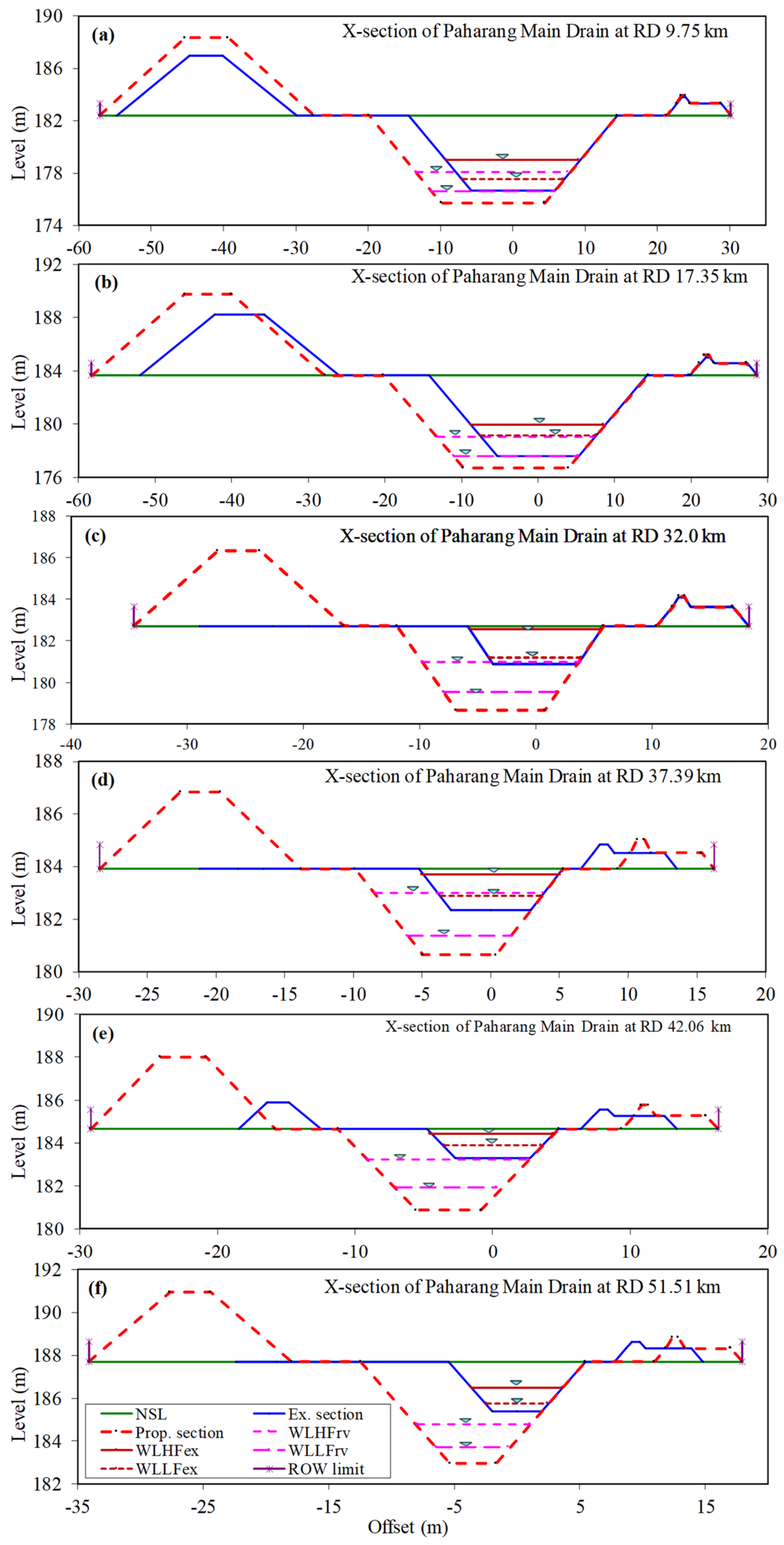
3.3. Redesigned Cross-Section
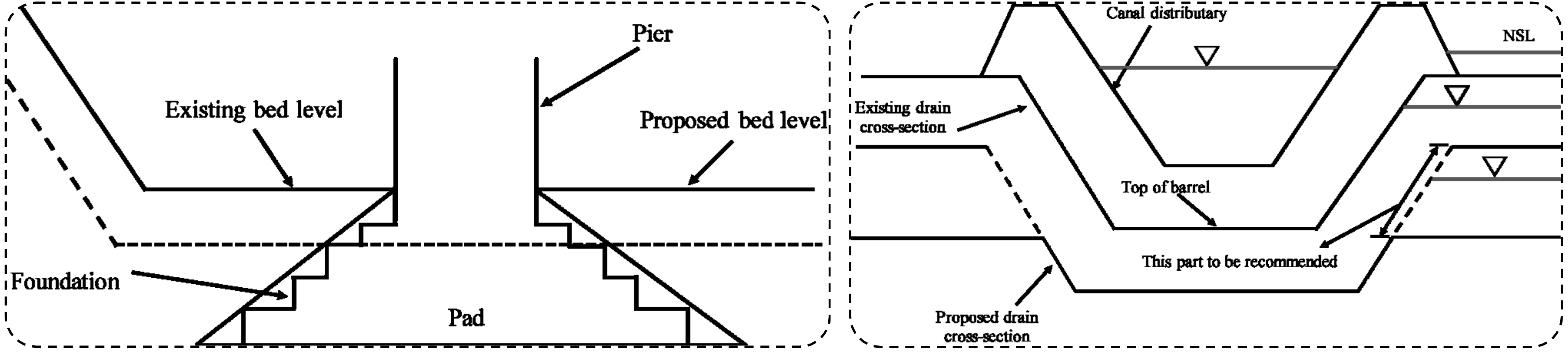
3.4. Modification in Hydraulic Structures
4. Conclusions
Author Contributions
Funding
Institutional Review Board Statement
Informed Consent Statement
Data Availability Statement
Acknowledgments
Conflicts of Interest
References
- Qureshi, A.S.; McCornick, P.G.; Qadir, M.; Aslam, Z. Managing salinity and waterlogging in the Indus Basin of Pakistan. Agric. Water Manag. 2008, 95, 1–10. [Google Scholar] [CrossRef]
- Qureshi, A.S. Groundwater Governance in Pakistan: From Colossal Development to Neglected Management. Water 2020, 12, 3017. [Google Scholar] [CrossRef]
- Cannell, R.Q.; Belford, R.K.; Gales, K.; Dennis, C.W.; Prew, R.D. Effects of waterlogging at different stages of development on the growth and yield of winter wheat. J. Sci. Food Agric. 1980, 31, 117–132. [Google Scholar] [CrossRef]
- Liu, H.; Li, M.; Zheng, X.; Wang, Y.; Anwar, S. Surface Salinization of Soil under Mulched. Water 2020, 12, 3031. [Google Scholar] [CrossRef]
- Mdrpk, D. Operation Updates Report Pakistan: Monsoon Floods; IFRC: Islamabad, Pakistan, 2020; pp. 1–21. Available online: https://reliefweb.int/sites/reliefweb.int/files/resources/MDRPK019du1.pdf (accessed on 9 March 2021).
- Hocking, P.J.; Reicosky, D.C.; Meyer, W.S. Effects of intermittent waterlogging on the mineral nutrition of cotton. Plant Soil 1987, 101, 211–221. [Google Scholar] [CrossRef]
- Manik, S.M.N.; Pengilley, G.; Dean, G.; Field, B.; Shabala, S.; Zhou, M. Soil and Crop Management Practices to Minimize the Impact of Waterlogging on Crop Productivity. Front. Plant Sci. 2019, 10, 140. [Google Scholar] [CrossRef] [Green Version]
- Estimating Long-Term Regional Groundwater Recharge for the Evaluation of Potential Solution Alternatives to Waterlogging and Salinisation-ScienceDirect. Available online: https://0-www-sciencedirect-com.brum.beds.ac.uk/science/article/pii/S0022169411004434?casa_token=LQtlR1vdwh0AAAAA:bZwfRpx1CZgPAxG-b4RC3iAX4cNEuAPcVrZ7QNZoEnVTfOAwlGBrHa_uxFLVnBRWS-2D13b4Wg (accessed on 9 March 2021).
- Chandio, A.S.; Lee, T.S.; Mirjat, M.S. Simulation of horizontal and vertical drainage systems to combat waterlogging problems along the Rohri Canal in Khairpur District, Pakistan. J. Irrig. Drain. Eng. 2013, 139, 710–717. [Google Scholar] [CrossRef] [Green Version]
- Ritzema, H.P.; Satyanarayana, T.V.; Raman, S.; Boonstra, J. Subsurface drainage to combat waterlogging and salinity in irrigated lands in India: Lessons learned in farmers’ fields. Agric. Water Manag. 2008, 95, 179–189. [Google Scholar] [CrossRef]
- Gupta, S.K. Sub-surface drainage for waterlogged saline soils. Water Energy Int. 1985, 42, 335–344. [Google Scholar]
- Velmurugan, A.; Swarnam, T.P.; Ambast, S.K.; Kumar, N. Managing waterlogging and soil salinity with a permanent raised bed and furrow system in coastal lowlands of humid tropics. Agric. Water Manag. 2016, 168, 56–67. [Google Scholar] [CrossRef]
- Bakker, D.M.; Hamilton, G.J.; Houlbrooke, D.J.; Spann, C. The effect of raised beds on soil structure, waterlogging, and productivity on duplex soils in Western Australia. Soil Res. 2005, 43, 575–585. [Google Scholar] [CrossRef]
- Sayre, K.D.; Moreno Ramos, O.H. Applications of Raised-Bed Planting Systems to Wheat; CIMMYT: El Batan, Mexico, 1997; ISBN 9706480005. [Google Scholar]
- Johnson, S. Large scale irrigation and drainage schemes in Pakistan: A study of rigidities in public decision making. Food Res. Inst. Stud. 1982, 18, 149–180. [Google Scholar]
- Tariq, A.-R. Drainage System Engineering; Center of Excellence in Water Resources Engineering, University of Engineering and Technology: Lahore, Pakistan, 2008. [Google Scholar]
- Smedema, L.K.; Abdel-Dayem, S.; Ochs, W.J. Drainage and agricultural development. Irrig. Drain. Syst. 2000, 14, 223–235. [Google Scholar] [CrossRef]
- Qureshi, A.S.; McCornick, P.G.; Sarwar, A.; Sharma, B.R. Challenges and prospects of sustainable groundwater management in the Indus Basin, Pakistan. Water Resour. Manag. 2010, 24, 1551–1569. [Google Scholar] [CrossRef] [Green Version]
- Kelleners, T.J.; Chaudhry, M.R. Drainage water salinity of tubewells and pipe drains: A case study from Pakistan. Agric. Water Manag. 1998, 37, 41–53. [Google Scholar] [CrossRef]
- Waller, P.; Yitayew, M. Subsurface Drainage Design and Installation BT-Irrigation and Drainage Engineering; Waller, P., Yitayew, M., Eds.; Springer International Publishing: Cham, Germany, 2016; pp. 531–544. ISBN 978-3-319-05699-9. [Google Scholar]
- Hamid, Y. Experience Gained from Interceptor Drains Installed in LBOD Stage-1 Project; Water and Agriculture Division NESPAK: Lahore, Pakistan, 1998; Available online: https://pecongress.org.pk/images/upload/books/578.pdf (accessed on 9 March 2021).
- Llor, M.; Bel, A.; Ortuño, J.F.; Meseguer, F. Oxygen Consumption in Two Subsurface Wastewater Infiltration Systems under Continuous Operation Mode. Water 2020, 12, 3007. [Google Scholar]
- Huang, P.; Han, S. Assessment by multivariate analysis of groundwater-surface water interactions in the Coal-mining Exploring District, China. Earth Sci. Res. J. 2016, 20, G1–G8. [Google Scholar] [CrossRef]
- Sohag, S. Groundwater Investigation in Awlad Salameh. Earth Sci. Res. J. 2010, 14, 63–75. [Google Scholar]
- Fortier, S.; Scobey, F.C. Permissible Canal Velocities. Trans. Am. Soc. Civ. Eng. 1926, 89, 940–949. [Google Scholar] [CrossRef]
- Ritzema, H.P.; Nijland, H.J.; Croon, F.W. Subsurface drainage practices: From manual installation to large-scale implementation. Agric. Water Manag. 2006, 86, 60–71. [Google Scholar] [CrossRef]
- Government of Pakistan. Surface Drainage Manual for Pakistan: Irrigation System Management Project: II, USAID Project Number 391-0467. Government of Pakistan: Islamabad, Pakistan, 1993. [Google Scholar]
- Rilinger, G. Toward a Sociology of Economic Engineering: The Creation and Collapse of California’s Electricity Markets between 1993 and 2001. Ph.D. Thesis, The University of Chicago, Chicago, IL, USA, 2020. [Google Scholar]
- Deshmukh, S.; Pansare, K.; Balsane, V.; Borse, K.; Samtani, B.K. Analytical study of quantitatvie chracheterists of watershed between Tapi and Wansuki distry River of Kakarapar and Ukai Command Area. Ecol. Environ. Conserv. 2015, 21, 345–354. [Google Scholar]
- Fisher, L. Minnesota Water Management Law and Section 404 Permits: A Practitioner’s Perspective. Hamline L. Rev. 1984, 7, 249. [Google Scholar]
- Simons, D.B.; Richardson, E.V. A study of variables affecting flow characteristics and sediment transport in alluvial channels. In Proceedings of the Federal Interagency Sedimentation Conference, Agricultural Research Service; U.S. Department of Agriculture: Jackson, MI, USA, 1963; pp. 193–206. [Google Scholar]
- Witaschek, F.V. International Control of River Water Pollution. Denver J. Int. Law Policy 2020, 2, 6. [Google Scholar]
- Simons, D.B.; Rlchardson, E.V.; Nordin, C.F., Jr. Sedimentary structures generated by flow in alluvial channels. AAPG Bull. 1964, 48, 547. [Google Scholar]
- Lackey, K.A. Innovation in large capacity wastewater pumping station design. In Proceedings of the NC AWWA-WEA, WInston-Salem, NC, USA, 14–17 November 2010. [Google Scholar]
- Okwany, R.O.; Prathapar, S.; Bastakoti, R.C.; Mondal, M.K. Shallow Subsurface Drainage for Managing Seasonal Flooding in Ganges Floodplain, Bangladesh. Irrig. Drain. 2016, 65, 712–723. [Google Scholar] [CrossRef] [Green Version]


| Drain | RD (km) | BLO (m) | BLR (m) | WLHFO (m) | WLHFR (m) | WLLFO (m) | WLLFR (m) |
|---|---|---|---|---|---|---|---|
| Sarangwala Branch | 28.91 | 178.5 | 178.2 | 180.6 | 180.6 | 179.7 | 179.2 |
| 195 Try. Drain | 37.21 | 181.7 | 180.4 | 183.1 | 182.7 | 182.0 | 181.2 |
| Karari Try. Drain | 39.81 | 181.6 | 180.7 | 183.2 | 183.1 | 181.9 | 181.7 |
| NIPALKE Try. | 43.31 | 181.5 | 181.1 | 183.8 | 183.5 | 182.3 | 182.0 |
| 159 Try. Drain | 50.57 | 184.0 | 182.8 | 184.8 | 183.5 | 184.5 | 183.6 |
| Gojra Drain | 50.57 | 184.0 | 182.8 | 184.7 | 184.5 | 184.3 | 183.6 |
| Gunna Branch | 53.91 | 183.5 | 183.2 | 184.7 | 184.4 | 184.2 | 184.0 |
| Reach (km) | B (m) | dHF (m) | BS | V (m/s) | High Q (m3/s) | dLF (m) | Low Q (m3/s) |
|---|---|---|---|---|---|---|---|
| H:1V | |||||||
| 0–7.16 | 11.28 | 7.9 | 5000 | 0.52 | 18.58 | 0.74 | 2.72 |
| 7.16–9.14 | 15.1 | 7.7 | 8000 | 0.42 | 18.39 | 0.74 | 2.69 |
| 9.14–12.80 | 14.32 | 7.7 | 8000 | 0.42 | 17.50 | 0.76 | 2.60 |
| 12.80–17.04 | 14.02 | 7.7 | 8000 | 0.42 | 17.16 | 0.77 | 2.58 |
| 17.04–22.55 | 13.72 | 7.7 | 8000 | 0.41 | 16.82 | 0.78 | 2.58 |
| 22.55–25.42 | 10.82 | 7.7 | 8000 | 0.40 | 13.59 | 0.90 | 2.55 |
| 25.42–30.05 | 9.30 | 7.7 | 8000 | 0.40 | 11.92 | 0.98 | 2.49 |
| 30.05–31.09 | 7.77 | 7.7 | 8000 | 0.39 | 10.25 | 0.88 | 1.81 |
| 31.09–34.14 | 7.62 | 7.7 | 8000 | 0.38 | 10.08 | 0.89 | 1.81 |
| 34.14–40.84 | 5.33 | 7.7 | 8000 | 0.36 | 7.61 | 0.93 | 1.38 |
| 40.84–45.11 | 4.72 | 7.7 | 8000 | 0.36 | 6.96 | 0.91 | 1.22 |
| 45.11–50.29 | 4.72 | 6 | 8000 | 0.32 | 4.30 | 0.68 | 0.74 |
| 50.29–53.95 | 3.66 | 6 | 8000 | 0.30 | 3.57 | 0.68 | 0.57 |
| 53.95–57.30 | 6.10 | 4 | 4500 | 0.35 | 3.40 | 0.76 | 0.57 |
| 57.30–58.12 | 4.57 | 4 | 4500 | 0.34 | 2.63 | 0.87 | 0.57 |
| 58.12–59.65 | 3.05 | 3.5 | 4500 | 0.30 | 1.47 | 0.87 | 0.57 |
| RD (km) | NSL (m) | Existing Bed Level (m) | Design Bed Level (m) | WLHFRV (m) | WLLFRV (m) | WLHFEX (m) | WLHFEX (m) | Additional ROW (m) | |
|---|---|---|---|---|---|---|---|---|---|
| Left | Right | ||||||||
| 7.62 | 182.91 | 175.98 | 175.47 | 177.82 | 176.39 | 178.32 | 177.07 | 0 | 0 |
| 9.75 | 182.41 | 176.65 | 175.73 | 178.08 | 179.68 | 179.0 | 177.54 | 2.34 | 0 |
| 13.72 | 182.93 | 177.08 | 176.23 | 178.58 | 177.13 | 179.43 | 177.64 | 3.59 | 0 |
| 17.35 | 183.65 | 177.59 | 176.69 | 179.04 | 177.60 | 179.94 | 179.15 | 60.32 | 0 |
| 19.81 | 180.21 | 178.15 | 176.99 | 179.34 | 177.60 | 179.88 | 179.17 | 6.34 | 0 |
| 26.82 | 181.75 | 179.62 | 178.15 | 180.35 | 178.98 | 181.08 | 181.06 | 1.06 | 0 |
| 32.00 | 182.71 | 180.89 | 178.65 | 181.0 | 189.05 | 182.56 | 181.19 | 4.09 | 0 |
| 37.39 | 183.91 | 182.34 | 180.64 | 182.99 | 178.17 | 183.69 | 182.90 | 7.27 | 2.68 |
| 42.06 | 184.65 | 183.29 | 180.87 | 183.22 | 181.36 | 184.41 | 183.86 | 10.77 | 2.99 |
| 49.07 | 185.95 | 184.91 | 182.66 | 184.49 | 18.32 | 185.82 | 185.21 | 13.85 | 0 |
| 51.51 | 187.69 | 185.39 | 182.95 | 184.78 | 183.71 | 186.49 | 185.76 | 11.69 | 10.3 |
| Name | RD (km) | Existing DBL (m) | Proposed DBL (m) | Difference in DBL (m) |
|---|---|---|---|---|
| Aquaduct of Khaliana | 12.809 | 176.68 | 176.26 | 0.43 |
| Aquaduct of Nasrana | 17.034 | 177.52 | 176.78 | 0.74 |
| Aquaduct of Sarangwala Disty. | 31.320 | 180.93 | 178.56 | 2.36 |
Publisher’s Note: MDPI stays neutral with regard to jurisdictional claims in published maps and institutional affiliations. |
© 2021 by the authors. Licensee MDPI, Basel, Switzerland. This article is an open access article distributed under the terms and conditions of the Creative Commons Attribution (CC BY) license (https://creativecommons.org/licenses/by/4.0/).
Share and Cite
Imran, M.A.; Xu, J.; Sultan, M.; Shamshiri, R.R.; Ahmed, N.; Javed, Q.; Asfahan, H.M.; Latif, Y.; Usman, M.; Ahmad, R. Free Discharge of Subsurface Drainage Effluent: An Alternate Design of the Surface Drain System in Pakistan. Sustainability 2021, 13, 4080. https://0-doi-org.brum.beds.ac.uk/10.3390/su13074080
Imran MA, Xu J, Sultan M, Shamshiri RR, Ahmed N, Javed Q, Asfahan HM, Latif Y, Usman M, Ahmad R. Free Discharge of Subsurface Drainage Effluent: An Alternate Design of the Surface Drain System in Pakistan. Sustainability. 2021; 13(7):4080. https://0-doi-org.brum.beds.ac.uk/10.3390/su13074080
Chicago/Turabian StyleImran, Muhammad Ali, Jinlan Xu, Muhammad Sultan, Redmond R. Shamshiri, Naveed Ahmed, Qaiser Javed, Hafiz Muhammad Asfahan, Yasir Latif, Muhammad Usman, and Riaz Ahmad. 2021. "Free Discharge of Subsurface Drainage Effluent: An Alternate Design of the Surface Drain System in Pakistan" Sustainability 13, no. 7: 4080. https://0-doi-org.brum.beds.ac.uk/10.3390/su13074080