
Review on the Test Methods and Devices for Mechanical Properties of Hydrate-Bearing Sediments

 ,
,  , ,
, ,
Abstract
:1. Introduction
2. Current Progress on HBS Mechanical Testing Methods
2.1. Mechanical Properties Characterization Techniques of HBS under Small Strain
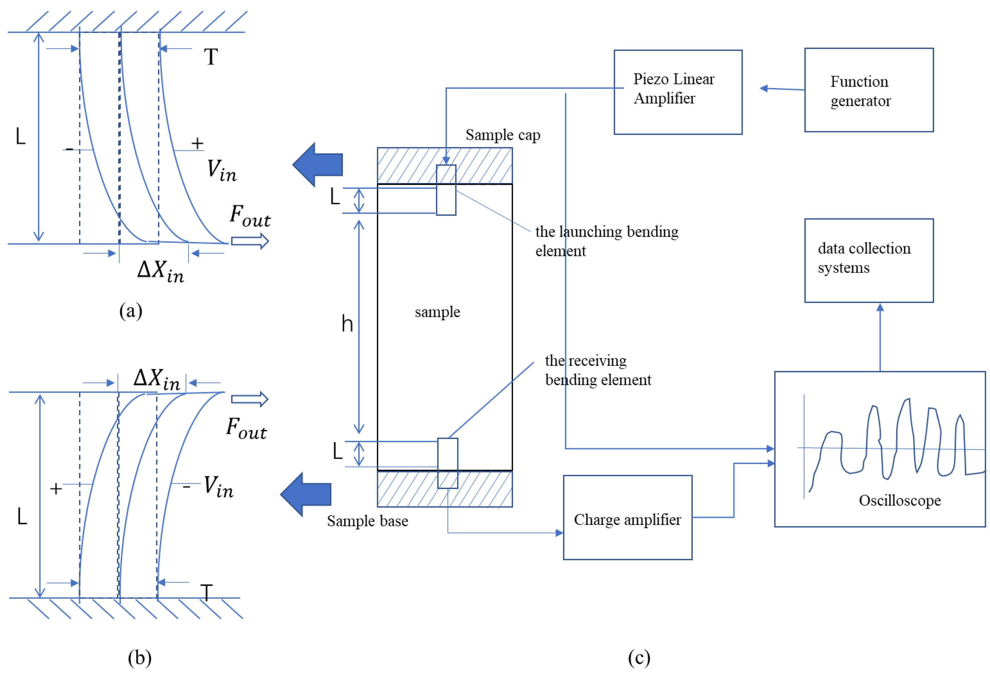
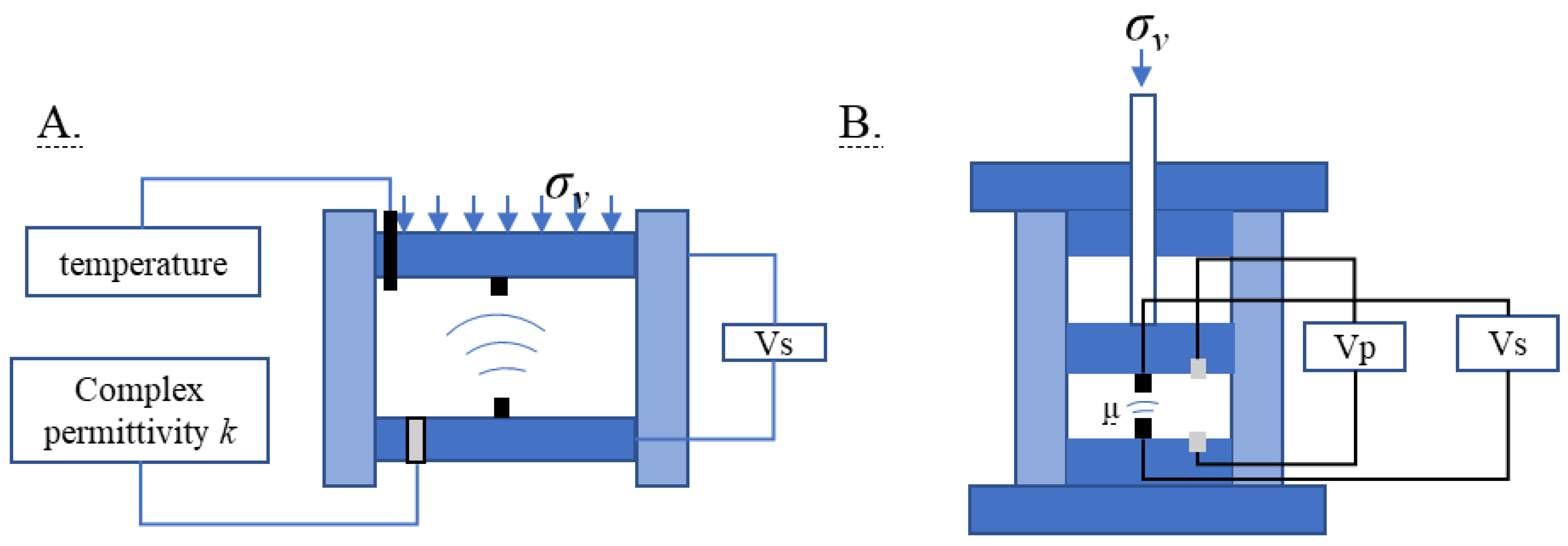
2.1.1. Bender Elements Testing Method
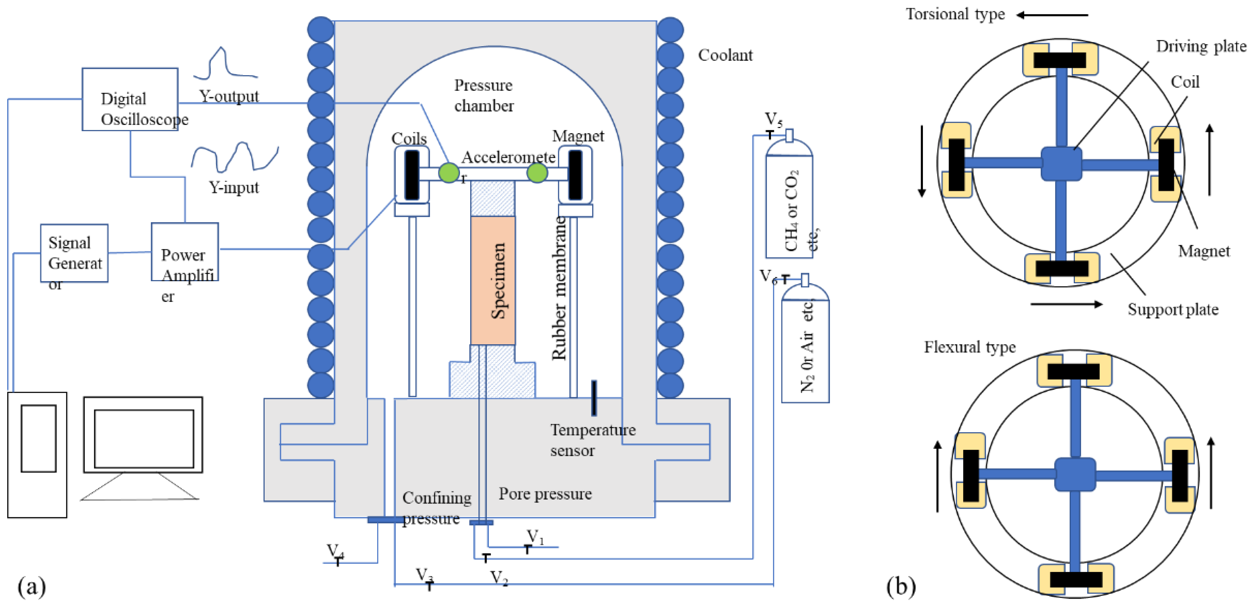
2.1.2. Resonance Column Testing Method

| References | Size (mm) | Test Indicators | Vibration Frequency (Hz) | Shear Strain (%) | Important Discovery |
|---|---|---|---|---|---|
| Cascante et al. (1998) [47] | Φ 71 × 136 | Shear and longitudinal stiffness | 50–200 | 10−6–10−5 | P and S waves are affected by stress state but are almost insensitive to the stress history. |
| Clayton et al. (2005) [57] | Φ 70 × 140 | Shear and longitudinal stiffness | NA | 10−6 | Hydrate bonding has considerably less impact on bulk modulus. |
| Priest et al. (2005) [58] | Φ 70 × 140 | Compression and shear-wave velocity | 17–400 | 10−5 | A dichotomous relationship was exhibited between compressional and shear wave velocities with hydrate saturation. |
| Best et al. (2013) [59] | Φ 70 × 140 | Compression and shear-wave velocity | 50–550 | 10−4 | Hydrate synthesis methods significantly affect the attenuation properties of shear wave velocity and compression wave velocity. |
| Liu et al. (2020) [50] | Φ 70 × 140 | Compression and shear-wave velocity | 146–154 | 10−6–10−4 | Wave attenuation of tested specimens decreases with increasing effective confining stress and increases with increasing hydrate saturation. |
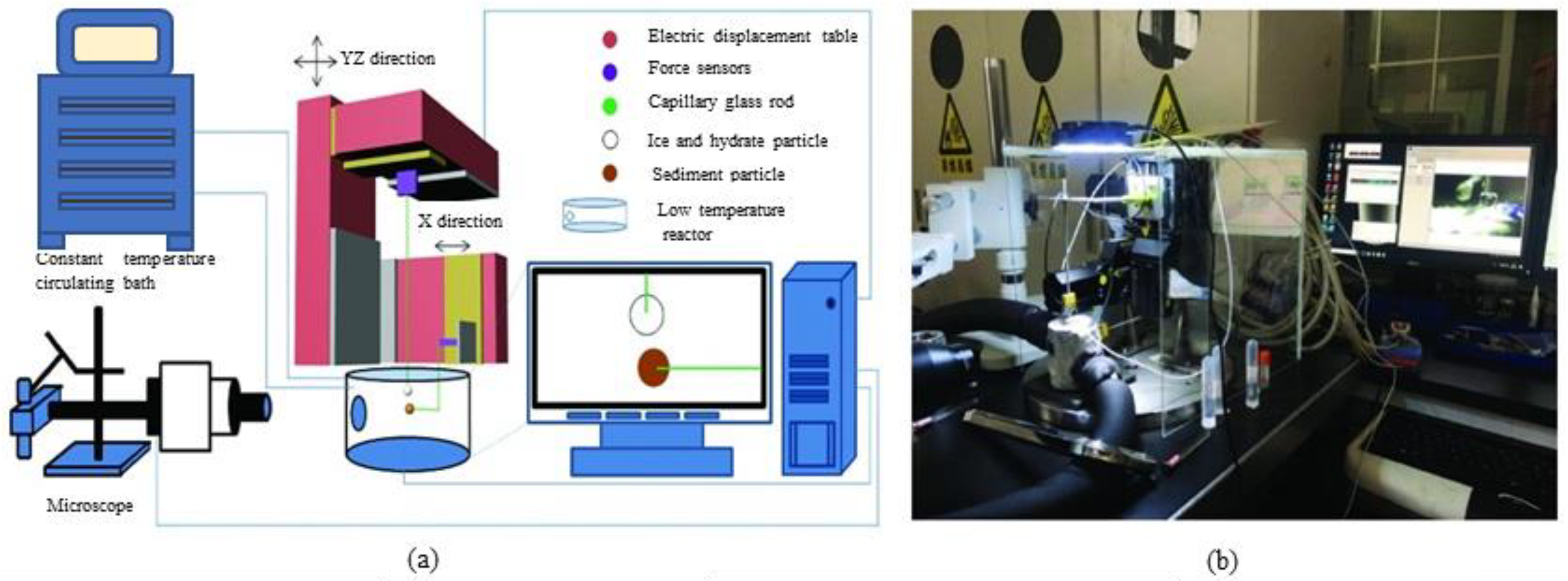
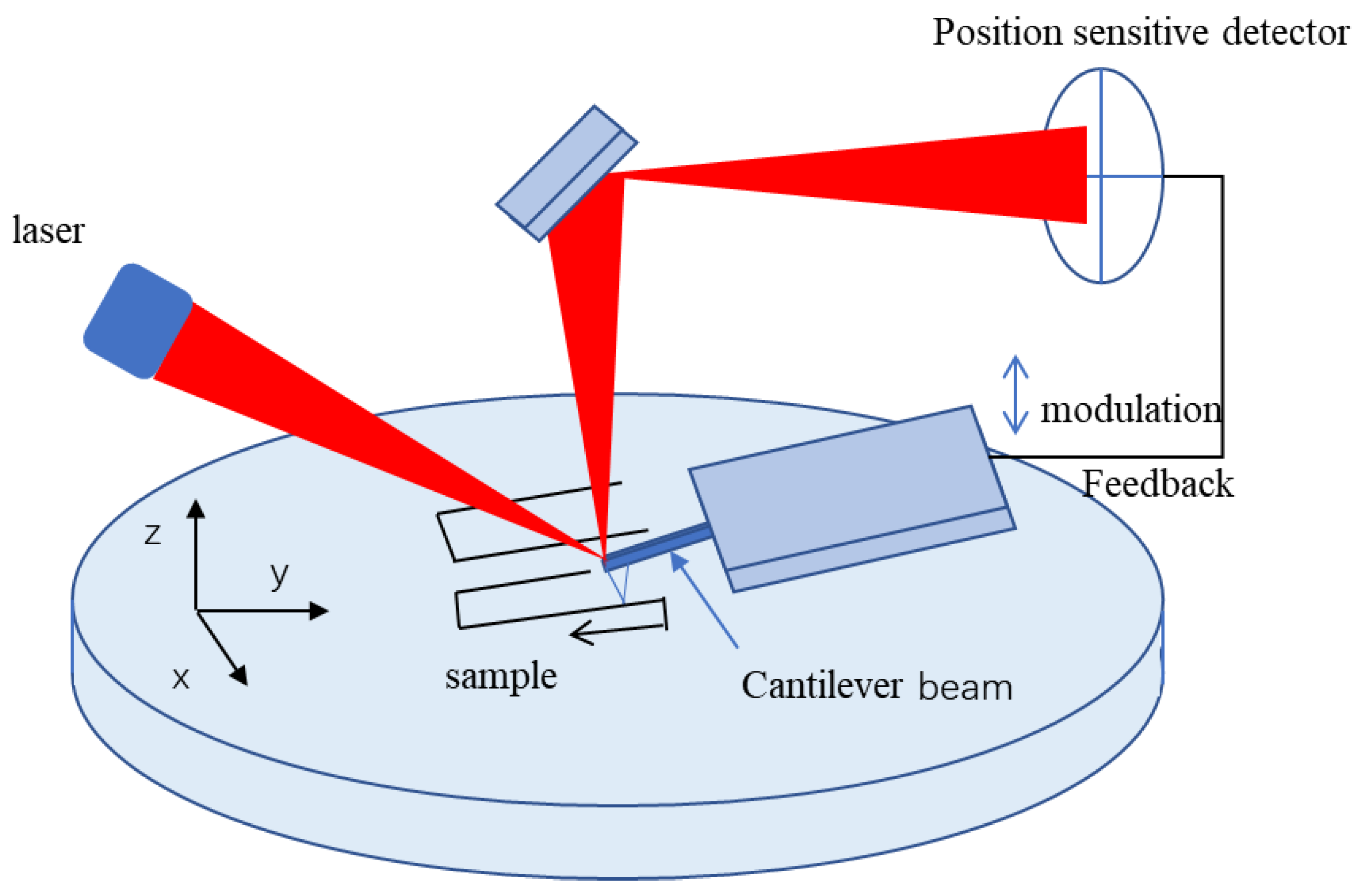
2.1.3. Other Promising Techniques

2.2. Current Progress in a Triaxial Shear Test of HBS
2.2.1. Core-Scale Triaxial Shear Devices for HBS

| Unit Properties | Dalian University of Technology, China | Dalian University of Technology, China | National Institute of Advanced Industrial Science and Technology, Tsukuba, Japan | Yamaguchi University, Japan | Heriot-Watt University, Edinburgh, UK | Institute of Mechanics, Chinese Academy of Sciences, China | Guangzhou Institute of Energy Conversion, Chinese Academy of Sciences, China | Qingdao Institute of Marine Geology, China Geological Survey, China |
|---|---|---|---|---|---|---|---|---|
| Type | DDW-600 | NA | NA | NA | Tri-Scan 250 | NA | NA | TSZ-2 |
| Sample size (mm) | Φ 61.8 × 125 | Φ 50 × 100 | Φ 50 × 100 | Φ 30 × 60 | Φ 50 × 100 | Φ 39.1 × 80 | Φ 50 × 100 | Φ 39.1 × 120 |
| Temperature Control range (°C) | −30–25 | −20–25 | −20–20 | −35–50 | −20–50 | −20–20 | −30–50 | −20–40 |
| Confining pressure range (MPa) | 0–25 | 0–30 | 0–20 | 0–30 | 0–40 | 0–14 | 0–30 | 0–15 |
| Temperature control pattern | Constant temperature pump + heat exchanger | Constant temperature pump + heat exchanger | Refrigeration tank cooling (Glycol) | Incubator | Constant temperature water bath | Incubator | Constant temperature water bath | Incubator |
| Temperature control accuracy (°C) | ±0.5 | ±0.5 | ±0.5 | ±0.1 | NA | ±0.5 | NA | ±0.1 |
| Pressure control accuracy (MPa) | ±0.01 | ±0.01 | NA | ±0.1 | NA | ±0.098 | 0.2%F.S | ±0.015 |
| External monitoring | NA | NA | NA | NA | NA | NA | NA | Wave monitor |
| Maximum loading capacity (KN) | 600 | 60 | 200 | 200 | 250 | NA | 250 | 50 |
| Volume strain | NA | NA | yes | yes | yes | NA | NA | NA |
| References | Luo et al. (2016) [72] | Li et al. (2011) [22] | Miyazaki et al. (2011) [23] | Hyodo et al. (2014) [82] | Yang et al. (2019) [83] | Zhang et al. (2010) [84] | Guan et al. (2017) [85] | Dong et al. (2020) [25] |
- (1)
- No reference standard for sample preparation, hindering the comparison of the mechanical behavior of different triaxial shear experiments. Reported sample sizes are various, and the overall height–diameter ratio is about 2:1. Due to large differences in sample size and experimental conditions between different triaxial shear experiments, the experimental results reported in different kinds of literature cannot be directly compared. It is recommended to standardize the relevant specifications for sample preparation and testing for analysis of different test results.
- (2)
- The sample preparation size of a specific triaxial shear instrument is fixed, which is not beneficial for the mechanical testing of different height samples in the same instrument. Additionally, it is also inconvenient to determine the scale effect of the sample.
- (3)
- Coarse-grained sand is mainly used for sample preparation, and less from situ sediments on the seabed. To address the difficulty in synthesizing hydrates from deep-sea silty sediments, it is recommended to strengthen the research and development of sample-preparation technology.
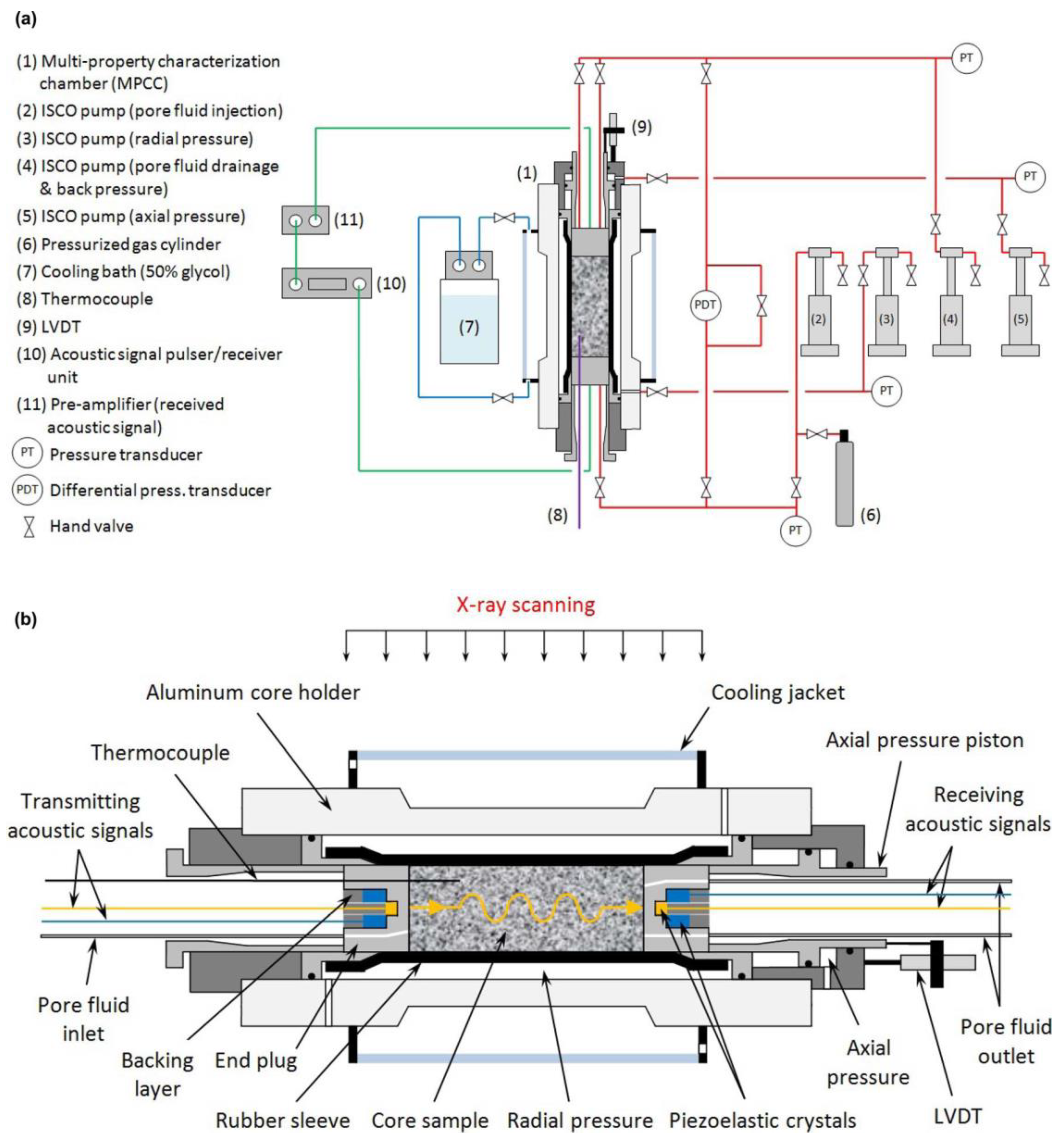
2.2.2. X-CT Based Triaxial Shear Devices
2.2.3. Triaxial Shear Device for Pressure-Coring Samples
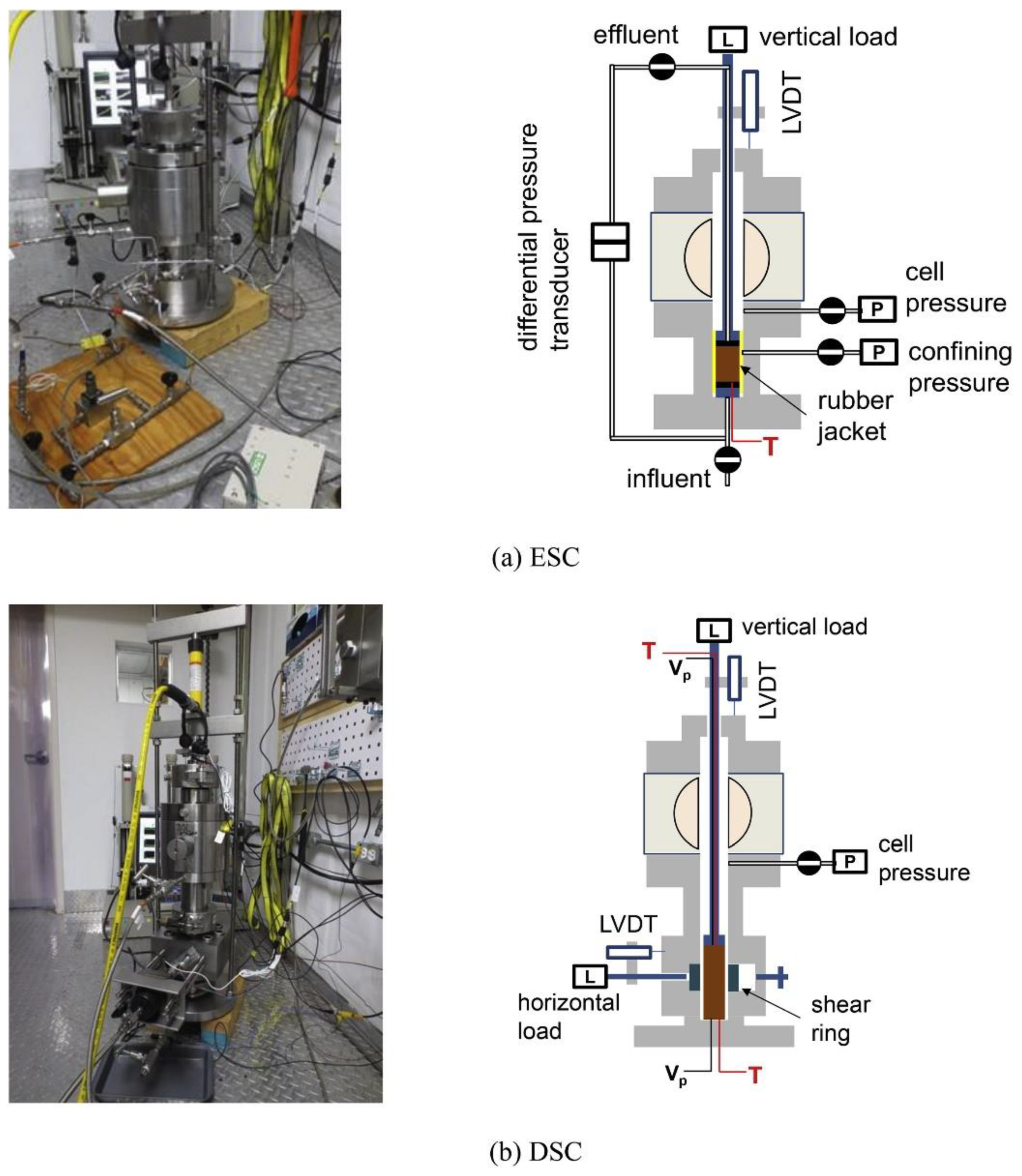
2.3. Current Progress of Direct Shear in HBS
2.4. Development of Ring Shear Test Method
| References | Inside Diameter (mm) | Outside Diameter (mm) | Height (mm) | Maximum Normal Loading (MPa) | Shear Ratios (mm/min) | Normal Loading Method |
|---|---|---|---|---|---|---|
| Kimura et al. (2014) [117] | 55 | 75 | 20 | 10 | 0.2–1020 | pneumatic piston |
| Spangenberg et al. (2020) [31] | 30 | 50 | 25 ± 5 | 30 | 0.08–4.0 | hydraulic piston |
2.5. Cone-Penetration Testing Method
3. Discussion
3.1. On the Cross-Scale Analysis of Mechanical Properties of HBS
- (1)
- Currently, mechanical tests focus mainly on the short-term failure of HBS, lacking comparability in the mechanical properties obtained from different experiments. Even for a widely used test method such as triaxial shear, there is no unified standard in sample synthesis and error analysis. In addition, no study considers the effect of sample size on the mechanics of HBS, and it remains to be clarified whether the mechanical parameters measured by various experimental instruments can be directly used in the reservoir deformation simulation of hydrate production at trial. Therefore, strengthening the formulation of relevant test-process specifications and increasing the development of unified standard sample preparation equipment would be recommended. The innovation in the hydrate synthesis method for clayey-silt sediments needs to be strengthened, mainly to solve the difficulty of hydrate synthesis in in-situ seabed soil.
- (2)
- At present, most of the synthetic samples, assuming that all gas or liquid is consumed during synthesis, used for hydrate mechanical tests are homogeneous. Due to a lack of monitoring of hydrate distribution after sample synthesis, mechanical test values may deviate from true values. Therefore, improving the monitoring technology for hydrate distribution would be of great importance in quantifying the relationship between hydrate heterogeneity and mechanical properties. Furthermore, research on the heterogeneity of hydrate sediments is mainly based on numerical simulation, and the mechanical properties of heterogeneous samples are still unclear, as a result of the lack of experimental results.
- (3)
- In-situ mechanical results of hydrate reservoirs often only reflect the mechanical properties of sediments at specific sampling points at different depths, lacking sufficient data of different sites in the overall understanding of the mechanical behavior of the reservoirs. In addition, in-situ lateral mechanical test instruments and related mechanical theories urgently need to make breakthroughs considering the wellbore.
3.2. Main Challenges and Development Tendency
- (1)
- Defining and clarifying the feasibility of experimental test results to guide trial production is a major challenge for future hydrate mechanical research. The ratio between experimental results and monitoring results on site is unclear and there are many uncertainties about whether the experimental results can reflect the mechanical characteristics of an actual hydrate reservoir. Whether the laboratory test results can be directly used to predict the mechanical failure of field reservoirs remains unclear, and it is difficult to eliminate the public concerns about the development of hydrates that may lead to geological disasters and environmental problems.
- (2)
- How to unify the mechanical parameters obtained by various testing methods and form an overall understanding of the mechanical properties of HBS is another major challenge for the future mechanical test theories of HBS. Current mechanical tests just focus on the single deformation progress of HBS under a specific condition, while the mechanical progress from small-strain deformation to large-scale slides is a progressive process.
- (3)
- Monitoring the creep mechanics of field hydrate reservoirs and simulating the creep deformation under production conditions in the laboratory will be another challenge for future HBS mechanical test methods. In the process of hydrate production, the creep mechanical progress of HBS is a multi-physics coupling process, and clarifying its evolution mechanism is the key to judging whether a reservoir will undergo creep failure. However, the mechanical means of a hydrate sediment creep test is mainly the triaxial shear and other test equipment and theory is lacking.
4. Conclusions and Suggestions
- (1)
- It is necessary to formulate and improve the relevant operating specifications of the existing test methods, clarifying the correlation between the test results and the real mechanical properties of the reservoir. Heterogeneity is an inherent property of hydrate reservoirs; the research on the mechanical properties of heterogeneous hydrate sediments should be strengthened.
- (2)
- In the future, the development trend of hydrate mechanical test instruments should develop toward high precision, multifunctional integration, which requires strong theoretical coupling between each test module. Therefore, both experimental and numerical simulation analyses of hydrate reservoirs require a unified theory in depicting different mechanical deformation processes.
- (3)
- There is an urgent need for comprehensive cross-scale analyses of the mechanical properties of HBS, solving the theoretical problems faced in the usability between experimental results obtained by varying mechanical instruments and field trials.
Author Contributions
Funding
Conflicts of Interest
References
- Feng, Y.; Chen, L.; Suzuki, A.; Kogawa, T.; Okajima, J.; Komiya, A.; Maruyama, S. Numerical analysis of gas production from layered methane hydrate reservoirs by depressurization. Energy 2019, 166, 1106–1119. [Google Scholar] [CrossRef]
- Yu, T.; Guan, G.; Abudula, A. Production performance and numerical investigation of the 2017 offshore methane hydrate production test in the Nankai Trough of Japan. Appl. Energy 2019, 251, 113338. [Google Scholar] [CrossRef]
- Yu, T.; Guan, G.; Abudula, A.; Yoshida, A.; Wang, D.; Song, Y. Application of horizontal wells to the oceanic methane hydrate production in the Nankai Trough, Japan. J. Nat. Gas Sci. Eng. 2019, 62, 113–131. [Google Scholar] [CrossRef]
- Boswell, R. Is Gas Hydrate Energy Within Reach? Science 2009, 325, 957–958. [Google Scholar] [CrossRef] [PubMed]
- Wang, L.; Zhao, J.; Sun, X.; Wu, P.; Shen, S.; Liu, T.; Li, Y. Comprehensive review of geomechanical constitutive models of gas hydrate-bearing sediments. J. Nat. Gas Sci. Eng. 2021, 88, 103755. [Google Scholar] [CrossRef]
- Wu, P.; Li, Y.; Sun, X.; Liu, W.; Song, Y. Mechanical Characteristics of Hydrate-Bearing Sediment: A Review. Energy Fuels 2021, 35, 1041–1057. [Google Scholar] [CrossRef]
- Merey, S.; Sinayuc, C. Investigation of gas hydrate potential of the Black Sea and modelling of gas production from a hypothetical Class 1 methane hydrate reservoir in the Black Sea conditions. J. Nat. Gas Sci. Eng. 2016, 29, 66–79. [Google Scholar] [CrossRef]
- Li, Y.; Liu, C.; Liu, L.; Sun, J.; Liu, H.; Meng, Q. Experimental study on evolution behaviors of triaxial-shearing parameters for hydrate-bearing intermediate fine sediment. Adv. Geo-Energy Res. 2018, 2, 43–52. [Google Scholar] [CrossRef] [Green Version]
- Li, Y.; Hu, G.; Wu, N.; Liu, C.; Chen, Q.; Li, C. Undrained shear strength evaluation for hydrate-bearing sediment overlying strata in the Shenhu area, northern South China Sea. Acta Oceanol. Sin. 2019, 38, 114–123. [Google Scholar] [CrossRef]
- Zhang, M.; Niu, M.; Shen, S.; Dai, S.; Xu, Y. Review of natural gas hydrate dissociation effects on seabed stability. Nat. Hazards 2021, 107, 1035–1045. [Google Scholar] [CrossRef]
- He, Y.; Zhong, G.; Wang, L.; Kuang, Z. Characteristics and occurrence of submarine canyon-associated landslides in the middle of the northern continental slope, South China Sea. Mar. Pet. Geol. 2014, 57, 546–560. [Google Scholar] [CrossRef]
- Zhou, W.; Wang, Y.; Gao, X.; Zhu, W.; Xu, Q.; Xu, S.; Cao, J.; Wu, J. Architecture, evolution history and controlling factors of the Baiyun submarine canyon system from the middle Miocene to Quaternary in the Pearl River Mouth Basin, northern South China Sea. Mar. Pet. Geol. 2015, 67, 389–407. [Google Scholar] [CrossRef]
- Chen, D.; Wang, X.; Völker, D.; Wu, S.; Wang, L.; Li, W.; Li, Q.; Zhu, Z.; Li, C.; Qin, Z.; et al. Three dimensional seismic studies of deep-water hazard-related features on the northern slope of South China Sea. Mar. Pet. Geol. 2016, 77, 1125–1139. [Google Scholar] [CrossRef]
- Sun, Q.; Cartwright, J.; Wu, S.; Zhong, G.; Wang, S.; Zhang, H. Submarine erosional troughs in the northern South China Sea: Evidence for Early Miocene deepwater circulation and paleoceanographic change. Mar. Pet. Geol. 2016, 77, 75–91. [Google Scholar] [CrossRef]
- Li, Y.; Wu, N.; Ning, F.; Gao, D.; Hao, X.; Chen, Q.; Liu, C.; Sun, J. Hydrate-induced clogging of sand-control screen and its implication on hydrate production operation. Energy 2020, 206, 118030. [Google Scholar] [CrossRef]
- Freij-Ayoub, R.; Tan, C.; Clennell, B.; Tohidi, B.; Yang, J. A wellbore stability model for hydrate bearing sediments. J. Pet. Sci. Eng. 2007, 57, 209–220. [Google Scholar] [CrossRef]
- Kim, A.R.; Kim, J.T.; Cho, G.C.; Lee, J.Y. Methane Production from Marine Gas Hydrate Deposits in Korea: Thermal-Hydraulic-Mechanical Simulation on Production Wellbore Stability. J. Geophys. Res. Solid Earth 2018, 123, 9555–9569. [Google Scholar] [CrossRef]
- Yang, L.; Wang, J.; Yang, Y.; Sun, G. Numerical Analysis of Soil Deformation and Collapse Due to Hydrate Decomposition. ACS Omega 2021, 6, 5335–5347. [Google Scholar] [CrossRef]
- Aydin, H.; Merey, S. The effect of gas production from deeper conventional gas reservoirs on shallower gas hydrate layer stability: A case study in the conditions of the Sakarya gas field, Western Black Sea. J. Nat. Gas Sci. Eng. 2021, 94, 104103. [Google Scholar] [CrossRef]
- Dong, L.; Li, Y.; Liao, H.; Liu, C.; Chen, Q.; Hu, G.; Liu, L.-L.; Meng, Q. Strength estimation for hydrate-bearing sediments based on triaxial shearing tests. J. Pet. Sci. Eng. 2020, 184, 106478. [Google Scholar] [CrossRef]
- Dong, L.; Li, Y.; Liu, C.; Liao, H.; Chen, G.; Chen, Q.; Liu, L.; Hu, G. Mechanical Properties of Methane Hydrate-Bearing Interlayered Sediments. J. Ocean Univ. China 2019, 18, 1344–1350. [Google Scholar] [CrossRef]
- Li, Y.-H.; Song, Y.-C.; Yu, F.; Liu, W.-G.; Zhao, J.-F. Experimental study on mechanical properties of gas hydrate-bearing sediments using kaolin clay. China Ocean Eng. 2011, 25, 113–122. [Google Scholar] [CrossRef]
- Miyazaki, K.; Masui, A.; Sakamoto, Y.; Aoki, K.; Temma, N.; Yamaguchi, T. Triaxial compressive properties of artificial methane-hydrate-bearing sediment. J. Geophys. Res. Solid Earth 2011, 116, B06102. [Google Scholar] [CrossRef]
- Hyodo, M.; Li, Y.; Yoneda, J.; Nakata, Y.; Yoshimoto, N.; Nishimura, A.; Song, Y. Mechanical behavior of gas-saturated methane hydrate-bearing sediments. J. Geophys. Res. Solid Earth 2013, 118, 5185–5194. [Google Scholar] [CrossRef] [Green Version]
- Dong, L.; Wan, Y.; Li, Y.; Liao, H.; Liu, C.; Wu, N.; Leonenko, Y. 3D numerical simulation on drilling fluid invasion into natural gas hydrate reservoirs. Energy 2022, 241, 122932. [Google Scholar] [CrossRef]
- Zhao, Y.; Liu, L.; Kong, L.; Liu, C.; Wu, N. Advances in Micromechanical Properties of Hydrate-Bearing Soils. Chin. J. Theor. Appl. Mech. 2021, 53, 2119–2140. [Google Scholar]
- Lee, J.Y.; Francisca, F.M.; Santamarina, J.C.; Ruppel, C. Parametric study of the physical properties of hydrate-bearing sand, silt, and clay sediments: 2. Small-strain mechanical properties. J. Geophys. Res. Solid Earth 2010, 115, B11105. [Google Scholar] [CrossRef]
- Liu, Z.; Kim, J.; Hu, G.; Hu, W.; Ning, F. Geomechanical property evolution of hydrate-bearing sediments under dynamic loads: Nonlinear behaviors of modulus and damping ratio. Eng. Geol. 2021, 295, 106427. [Google Scholar] [CrossRef]
- Li, Y.; Dong, L.; Wu, N.; Nouri, A.; Liao, H.; Chen, Q.; Sun, J.; Liu, C. Influences of hydrate layered distribution patterns on triaxial shearing characteristics of hydrate-bearing sediments. Eng. Geol. 2021, 294, 106375. [Google Scholar] [CrossRef]
- Liu, Z.; Dai, S.; Ning, F.; Peng, L.; Wei, H.; Wei, C. Strength Estimation for Hydrate-Bearing Sediments from Direct Shear Tests of Hydrate-Bearing Sand and Silt. Geophys. Res. Lett. 2018, 45, 715–723. [Google Scholar] [CrossRef]
- Spangenberg, E.; Heeschen, K.U.; Giese, R.; Schicks, J.M. “Ester”—A new ring-shear-apparatus for hydrate-bearing sediments. Rev. Sci. Instrum. 2020, 91, 064503. [Google Scholar] [CrossRef] [PubMed]
- Sultan, N.; Garziglia, S. Geomechanical constitutive modelling of gas-hydrate-bearing sediments. In Proceedings of the 7th International Conference on Gas Hydrates, Edinburgh, UK, 17–21 July 2011. [Google Scholar]
- Nakashima, K.; Nakata, Y.; Hyodo, M.; Yoshimoto, N.; Hiraoka, S.; Kajiyama, S. Compressive characteristics of methane hydrate-bearing sands under isotropic consolidation. Soils Found. 2021, 61, 506–519. [Google Scholar] [CrossRef]
- Ye, Y. Development of the Experiment Detection Technique; Springer: Berlin/Heidelberg, Germany, 2012; pp. 19–87. [Google Scholar]
- Ye, Y.; Liu, C. Natural Gas Hydrates: Experimental Techniques and Their Applications; Springer-Verlag: Berlin/Heidelberg, Germany, 2013. [Google Scholar]
- Khan, Q.; Subramanian, S.; Wong, D.Y.; Ku, T. Bender elements in stiff cemented clay: Shear wave velocity (Vs) correction by applying wavelength considerations. Can. Geotech. J. 2019, 56, 1034–1041. [Google Scholar] [CrossRef] [Green Version]
- Lee, J.-S.; Santamarina, J.C. Bender Elements: Performance and Signal Interpretation. J. Geotech. Geoenviron. Eng. 2005, 131, 1063–1070. [Google Scholar] [CrossRef] [Green Version]
- Hu, G.-W.; Ye, Y.-G.; Zhang, J.; Diao, S.-B.; Liu, C.-L. Acoustic Properties of Hydrate-Bearing Unconsolidated Sediments Measured by the Bender Element Technique. Chin. J. Geophys. 2012, 55, 635–647. [Google Scholar] [CrossRef]
- Meixiu, J.; Yunin, C.; Bo, H. Method for precisely determining shear wave velocity of soil from bender element tests. Chin. J. Geotech. Eng. 2003, 25, 732–736. [Google Scholar]
- Hu, G.; Ye, Y.; Zhang, J.; Liu, C.; Li, Q. Acoustic response of gas hydrate formation in sediments from South China Sea. Mar. Pet. Geol. 2014, 52, 1–8. [Google Scholar] [CrossRef]
- Ji, L.; Chiu, A.C.; Ma, L.; Jian, C. Shear Modulus of Hydrate Bearing Calcareous Sand-Fines Mixture; EDP Sciences: Les Ulis, France, 2019. [Google Scholar]
- Kim, H.-S.; Cho, G.-C.; Kwon, T.-H. Effect of CO2 hydrate formation on seismic wave velocities of fine-grained sediments. Geochem. Geophys. Geosyst. 2013, 14, 1787–1799. [Google Scholar] [CrossRef]
- Guler, E.; Afacan, K.B. Dynamic behavior of clayey sand over a wide range using dynamic triaxial and resonant column tests. Geomech. Eng. 2021, 24, 105–113. [Google Scholar]
- Nakagawa, S. Split Hopkinson resonant bar test for sonic-frequency acoustic velocity and attenuation measurements of small, isotropic geological samples. Rev. Sci. Instrum. 2011, 82, 044901. [Google Scholar] [CrossRef] [Green Version]
- Song, B.; Tsinaris, A.; Anastasiadis, A.; Pitilakis, K.; Chen, W. Small-strain stiffness and damping of Lanzhou loess. Soil Dyn. Earthq. Eng. 2017, 95, 96–105. [Google Scholar] [CrossRef]
- Patiño, H.; Martínez, E.; Galindo, R. Dynamic Behavior of a Granular Medium Subjected to Resonant Column Tests: Application to Ottawa Sand. Geotech. Test. J. 2020, 43, 132–150. [Google Scholar] [CrossRef]
- Cascante, G.; Santamarina, C.; Yassir, N. Flexural excitation in a standard torsional-resonant column device. Can. Geotech. J. 1998, 35, 478–490. [Google Scholar] [CrossRef]
- Schaeffer, K.; Bearce, R.; Wang, J. Dynamic Modulus and Damping Ratio Measurements from Free-Free Resonance and Fixed-Free Resonant Column Procedures. J. Geotech. Geoenviron. Eng. 2013, 139, 2145–2155. [Google Scholar] [CrossRef]
- Wang, X.; Xia, T.; Zhang, L.; Ding, Z.; He, S.; Peng, Y. Effect of soil microstructure on the small-strain shear modulus of saline soil. Arab. J. Geosci. 2021, 14, 1. [Google Scholar] [CrossRef]
- Liu, Z.; Ning, F.; Hu, G.; Liu, L.; Liu, C.; Peng, L.; Wang, D.; Hu, W.; Zhang, Z. Characterization of seismic wave velocity and attenuation and interpretation of tetrahydrofuran hydrate-bearing sand using resonant column testing. Mar. Pet. Geol. 2020, 122, 104620. [Google Scholar] [CrossRef]
- Priest, J.A.; Rees, E.V.L.; Clayton, C.R.I. Influence of gas hydrate morphology on the seismic velocities of sands. J. Geophys. Res. Solid Earth 2009, 114, B11205. [Google Scholar] [CrossRef] [Green Version]
- Sultaniya, A.K.; Priest, J.A.; Clayton, C.R.I. Measurements of the changing wave velocities of sand during the formation and dissociation of disseminated methane hydrate. J. Geophys. Res. Solid Earth 2015, 120, 778–789. [Google Scholar] [CrossRef]
- Priest, J.A.; Best, A.I.; Clayton, C.R.I. Attenuation of seismic waves in methane gas hydrate-bearing sand. Geophys. J. Int. 2006, 164, 149–159. [Google Scholar] [CrossRef] [Green Version]
- Priest, J.A.; Druce, M.; Roberts, J.; Schultheiss, P.; Nakatsuka, Y.; Suzuki, K. PCATS Triaxial: A new geotechnical apparatus for characterizing pressure cores from the Nankai Trough, Japan. Mar. Pet. Geol. 2015, 66, 460–470. [Google Scholar] [CrossRef]
- Liu, Z.; Kim, J.; Lei, L.; Ning, F.; Dai, S. Tetrahydrofuran Hydrate in Clayey Sediments—Laboratory Formation, Morphology, and Wave Characterization. J. Geophys. Res. Solid Earth 2019, 124, 3307–3319. [Google Scholar] [CrossRef]
- Wang, D.; Liu, Z.; Ning, F.; Hu, W.; Peng, L.; Hu, G.; Zhang, Z.; Luo, Q.; Li, X.; Dou, X.; et al. Dynamic responses of THF hydrate-bearing sediments under small strain: Resonance column test. J. Nat. Gas Sci. Eng. 2020, 81, 103399. [Google Scholar] [CrossRef]
- Clayton, C.R.I.; Priest, J.A.; Best, A.I. The effects of disseminated methane hydrate on the dynamic stiffness and damping of a sand. Geotechnique 2005, 55, 423–434. [Google Scholar] [CrossRef]
- Priest, J.; Best, A.I.; Clayton, C.R.I. A laboratory investigation into the seismic velocities of methane gas hydrate-bearing sand. J. Geophys. Res. Solid Earth 2005, 110, B04102. [Google Scholar] [CrossRef]
- Best, A.I.; Priest, J.; Clayton, C.R.I.; Rees, E.V.L. The effect of methane hydrate morphology and water saturation on seismic wave attenuation in sand under shallow sub-seafloor conditions. Earth Planet. Sci. Lett. 2013, 368, 78–87. [Google Scholar] [CrossRef] [Green Version]
- Yamamoto, K. Overview and introduction: Pressure core-sampling and analyses in the 2012–2013 MH21 offshore test of gas production from methane hydrates in the eastern Nankai Trough. Mar. Pet. Geol. 2015, 66, 296–309. [Google Scholar] [CrossRef]
- Konno, Y.; Fujii, T.; Sato, A.; Akamine, K.; Naiki, M.; Masuda, Y.; Yamamoto, K.; Nagao, J. Key Findings of the World’s First Offshore Methane Hydrate Production Test off the Coast of Japan: Toward Future Commercial Production. Energy Fuels 2017, 31, 2607–2616. [Google Scholar] [CrossRef]
- Yu, Y.; Luo, Q.; Ning, F.; Lu, H.; Liu, Z.; Peng, L.; Wang, D.; Shi, H.; Liu, Z.; Duan, L. Direct measurement of the interaction forces between sediment particles in gas hydrate reservoirs (in Chinese). J. China Univ. Pet. (Ed. Nat. Sci.) 2021, 45, 7. [Google Scholar]
- Deng, Y.; Xu, L.; Lu, H.; Wang, H.; Shi, Y. Direct measurement of the contact angle of water droplet on quartz in a reservoir rock with atomic force microscopy. Chem. Eng. Sci. 2018, 177, 445–454. [Google Scholar] [CrossRef]
- Peng, L.; Ning, F.; LI, W.; CaO, P.; Liu, Z.; Wang, D.; Zhang, Z.; Sun, J.; Zhang, L.; Jiang, G. Investigation on the effect of growth temperature and contact interface on surface characteristics of THF clathrate hydrates by atomic force microscopy (in Chinese). Sci. Sin. Phys. Mech. Astron. 2019, 49, 034612. [Google Scholar] [CrossRef]
- Wood, E.L.; Avant, T.; Kim, G.S.; Lee, S.K.; Burchman, Z.; Hughes, J.M.; Sansoz, F. Size effects in bimetallic nickel–gold nanowires: Insight from atomic force microscopy nanoindentation. Acta Mater. 2014, 66, 32–43. [Google Scholar] [CrossRef]
- Meininger, G.A. The central importance of the cytoskeleton for increased cell stiffness in cardiovascular disease. Focus on “Diabetes increases stiffness of live cardiomyocytes measured by atomic force microscopy nanoindentation”. Am. J. Physiol. Cell Physiol. 2014, 307, C908. [Google Scholar] [CrossRef] [PubMed] [Green Version]
- Guan, D.; Li, H.; Tong, P. Experimental methods and recent progress in biomechanics using atomic force microscopy. J. Exp. Fluid Mech. 2020, 34, 57–66. [Google Scholar]
- Luo, T.; Li, Y.; Sun, X.; Shen, S.; Wu, P. Effect of sediment particle size on the mechanical properties of CH4 hydrate-bearing sediments. J. Pet. Sci. Eng. 2018, 171, 302–314. [Google Scholar] [CrossRef]
- Yun, T.S.; Santamarina, J.C.; Ruppel, C. Mechanical properties of sand, silt, and clay containing tetrahydrofuran hydrate. J. Geophys. Res. Solid Earth 2007, 112, B04106. [Google Scholar] [CrossRef]
- Li, Y.; Liu, C.; Liao, H.; Lin, D.; Bu, Q.; Liu, Z. Mechanical properties of the clayey-silty sediment-natural gas hydrate mixed system. Nat. Gas Ind. B 2021, 8, 154–162. [Google Scholar] [CrossRef]
- Li, Y.; Wu, N.; Gao, D.; Chen, Q.; Liu, C.; Yang, D.; Jin, Y.; Ning, F.; Tan, M.; Hu, G. Optimization and analysis of gravel packing parameters in horizontal wells for natural gas hydrate production. Energy 2021, 219, 119585. [Google Scholar] [CrossRef]
- Luo, T.; Song, Y.; Zhu, Y.; Liu, W.; Liu, Y.; Li, Y.; Wu, Z. Triaxial experiments on the mechanical properties of hydrate-bearing marine sediments of South China Sea. Mar. Pet. Geol. 2016, 77, 507–514. [Google Scholar] [CrossRef]
- Li, Y.; Liu, L.; Jin, Y.; Wu, N. Characterization and development of marine natural gas hydrate reservoirs in clayey-silt sediments: A review and discussion. Adv. Geo-Energy Res. 2021, 5, 75–86. [Google Scholar] [CrossRef]
- Li, K.; Liu, R.-M.; Kong, L.; Zhao, X.-B. Modeling the Mechanical Behavior of Gas Hydrate Bearing Sediments Based on Unified Hardening Framework. Geotech. Geol. Eng. 2019, 37, 2893–2902. [Google Scholar] [CrossRef]
- Song, Y.; Luo, T.; Madhusudhan, B.N.; Sun, X.; Liu, Y.; Kong, X.; Li, Y. Strength behaviors of CH4 hydrate-bearing silty sediments during thermal decomposition. J. Nat. Gas Sci. Eng. 2019, 72, 103031. [Google Scholar] [CrossRef]
- Yoneda, J.; Kida, M.; Konno, Y.; Jin, Y.; Morita, S.; Tenma, N. In Situ Mechanical Properties of Shallow Gas Hydrate Deposits in the Deep Seabed. Geophys. Res. Lett. 2019, 46, 14459–14468. [Google Scholar] [CrossRef] [Green Version]
- Liu, J.-W.; Li, X.-S.; Kou, X.; Wang, Y.; Li, L.-J. Analysis of Hydrate Heterogeneous Distribution Effects on Mechanical Characteristics of Hydrate-Bearing Sediments. Energy Fuels 2021, 35, 4914–4924. [Google Scholar] [CrossRef]
- Masui, A.; Haneda, H.; Ogata, Y.; Aoki, K. Effects of Methane Hydrate Formation On Shear Strength of Synthetic Methane Hydrate Sediments. In Proceedings of the Fifteenth International Offshore and Polar Engineering Conference, Seoul, Korea, 19–24 June 2005. [Google Scholar]
- Xu, W.; Germanovich, L.N. Excess pore pressure resulting from methane hydrate dissociation in marine sediments: A theoretical approach. J. Geophys. Res. Solid Earth 2006, 111, B01104. [Google Scholar] [CrossRef]
- Seol, Y.; Choi, J.-H.; Dai, S. Multi-property characterization chamber for geophysical-hydrological investigations of hydrate bearing sediments. Rev. Sci. Instrum. 2014, 85, 084501. [Google Scholar] [CrossRef]
- Choi, J.H.; Dai, S.; Lin, J.S.; Seol, Y. Multistage Triaxial Tests on Laboratory-Formed Methane Hydrate-Bearing Sediments. J. Geophys. Res. Solid Earth 2018, 123, 3347–3357. [Google Scholar] [CrossRef]
- Hyodo, M.; Li, Y.; Yoneda, J.; Nakata, Y.; Yoshimoto, N.; Nishimura, A. Effects of dissociation on the shear strength and deformation behavior of methane hydrate-bearing sediments. Mar. Pet. Geol. 2014, 51, 52–62. [Google Scholar] [CrossRef]
- Yang, J.; Hassanpouryouzband, A.; Tohidi, B.; Chuvilin, E.; Bukhanov, B.; Istomin, V.; Cheremisin, A. Gas Hydrates in Permafrost: Distinctive Effect of Gas Hydrates and Ice on the Geomechanical Properties of Simulated Hydrate-Bearing Permafrost Sediments. J. Geophys. Res. Solid Earth 2019, 124, 2551–2563. [Google Scholar] [CrossRef]
- Zhang, X.-H.; Wang, S.-Y.; Li, Q.-P.; Zhao, J.; Wang, A.-L. Experimental study of mechanical properties of gas hydrate deposits (in Chinese). Chin. J. Rock Soil Mech. 2010, 31, 3069–3074. [Google Scholar]
- Guan, J.A.; Lu, J.; Lian, D.; Li, D.; Wan, L. Preliminary Tri-Axial Mechanical Test on the Hydrate-Bearing Media from Shenhu Area of South China Sea under High Confining Pressures. Adv. New Renew. Energy 2017, 5, 40–46. [Google Scholar]
- Jin, Y.; Konno, Y.; Nagao, J. Pressurized subsampling system for pressured gas-hydrate-bearing sediment: Microscale imaging using X-ray computed tomography. Rev. Sci. Instrum. 2014, 85, 094502. [Google Scholar] [CrossRef]
- Jin, Y.; Konno, Y.; Yoneda, J.; Kida, M.; Nagao, J. In Situ Methane Hydrate Morphology Investigation: Natural Gas Hydrate-Bearing Sediment Recovered from the Eastern Nankai Trough Area. Energy Fuels 2016, 30, 5547–5554. [Google Scholar] [CrossRef]
- Yoneda, J.; Jin, Y.; Katagiri, J.; Tenma, N. Strengthening mechanism of cemented hydrate-bearing sand at microscales. Geophys. Res. Lett. 2016, 43, 7442–7450. [Google Scholar] [CrossRef] [Green Version]
- Jin, S.; Takeya, S.; Hayashi, J.; Nagao, J.; Kamata, Y.; Ebinuma, T.; Narita, H. Structure Analyses of Artificial Methane Hydrate Sediments by Microfocus X-ray Computed Tomography. Jpn. J. Appl. Phys. 2004, 43, 5673–5675. [Google Scholar] [CrossRef]
- Chen, X.; Verma, R.; Espinoza, D.N.; Prodanović, M. Pore-Scale Determination of Gas Relative Permeability in Hydrate-Bearing Sediments Using X-Ray Computed Micro-Tomography and Lattice Boltzmann Method. Water Resour. Res. 2018, 54, 600–608. [Google Scholar] [CrossRef]
- Lei, L.; Gai, X.; Seol, Y. Load-bearing characteristic of methane hydrate within coarse-grained sediments—Insights from isotropic consolidation. Mar. Pet. Geol. 2020, 121, 104571. [Google Scholar] [CrossRef]
- Lei, L.; Seol, Y. Pore-Scale Investigation of Methane Hydrate-Bearing Sediments Under Triaxial Condition. Geophys. Res. Lett. 2020, 47, e2019GL086448. [Google Scholar] [CrossRef]
- Wu, P.; Li, Y.; Liu, W.; Liu, Y.; Wang, D.; Song, Y. Microstructure Evolution of Hydrate-Bearing Sands During Thermal Dissociation and Ensued Impacts on the Mechanical and Seepage Characteristics. J. Geophys. Res. Solid Earth 2020, 125, e2019JB019103. [Google Scholar] [CrossRef]
- Wu, P.; Li, Y.; Liu, W.; Sun, X.; Kong, X.; Song, Y. Cementation Failure Behavior of Consolidated Gas Hydrate-Bearing Sand. J. Geophys. Res. Solid Earth 2020, 125, e2019JB018623. [Google Scholar] [CrossRef]
- Ta, X.H.; Yun, T.S.; Muhunthan, B.; Kwon, T. Observations of pore-scale growth patterns of carbon dioxide hydrate using X -ray computed microtomography. Geochem. Geophys. Geosyst. 2015, 16, 912–924. [Google Scholar] [CrossRef]
- Kerkar, P.B.; Horvat, K.; Jones, K.W.; Mahajan, D. Imaging methane hydrates growth dynamics in porous media using synchrotron X-ray computed microtomography. Geochem. Geophys. Geosyst. 2014, 15, 4759–4768. [Google Scholar] [CrossRef]
- Chen, X.; Espinoza, D.N. Ostwald ripening changes the pore habit and spatial variability of clathrate hydrate. Fuel 2018, 214, 614–622. [Google Scholar] [CrossRef]
- Mahabadi, N.; Dai, S.; Seol, Y.; Jang, J. Impact of hydrate saturation on water permeability in hydrate-bearing sediments. J. Pet. Sci. Eng. 2019, 174, 696–703. [Google Scholar] [CrossRef]
- Wei, J.; Wu, T.; Feng, X.; Liang, J.; Li, W.; Xie, R.; Wu, G. Physical Properties of Gas Hydrate-Bearing Pressure Core Sediments in the South China Sea. Geofluids 2021, 2021, 1–10. [Google Scholar] [CrossRef]
- Yoneda, J.; Masui, A.; Konno, Y.; Jin, Y.; Egawa, K.; Kida, M.; Ito, T.; Nagao, J.; Temma, N. Mechanical behavior of hydrate-bearing pressure-core sediments visualized under triaxial compression. Mar. Pet. Geol. 2015, 66, 451–459. [Google Scholar] [CrossRef]
- Zhao, J.; Zheng, J.-N.; Wang, X.; Dong, S.; Yang, M.; Song, Y. Effects of underlying gas on formation and gas production of methane hydrate in muddy low-permeability cores. Fuel 2022, 309, 122128. [Google Scholar] [CrossRef]
- Priest, J.A.; Hayley, J.L.; Smith, W.E.; Schultheiss, P.; Roberts, J. PCATS triaxial testing: Geomechanical properties of sediments from pressure cores recovered from the Bay of Bengal during expedition NGHP-02. Mar. Pet. Geol. 2019, 108, 424–438. [Google Scholar] [CrossRef]
- Jang, J.; Dai, S.; Yoneda, J.; Waite, W.F.; Stern, L.A.; Boze, L.-G.; Collett, T.S.; Kumar, P. Pressure core analysis of geomechanical and fluid flow properties of seals associated with gas hydrate-bearing reservoirs in the Krishna-Godavari Basin, offshore India. Mar. Pet. Geol. 2019, 108, 537–550. [Google Scholar] [CrossRef]
- Wang, B.; Sun, J.; Shen, F.; Li, W.; Zhang, W. Mechanism of wellbore instability in continental shale gas horizontal sections and its water-based drilling fluid countermeasures. Nat. Gas Ind. B 2020, 7, 680–688. [Google Scholar] [CrossRef]
- Merey, S. Geomechanical wellbore stability analysis for the wells drilled in the shallow sediments of the Mediterranean Sea. J. Pet. Sci. Eng. 2020, 186, 106714. [Google Scholar] [CrossRef]
- Wu, N.; Li, Y.; Wan, Y.; Sun, J.; Huang, L.; Mao, P. Prospect of marine natural gas hydrate stimulation theory and technology system. Nat. Gas Ind. B 2021, 8, 173–187. [Google Scholar] [CrossRef]
- Wang, J.-J.; Guo, J.-J.; Bai, J.-P.; Wu, X. Shear strength of sandstone–mudstone particle mixture from direct shear test. Environ. Earth Sci. 2018, 77, 442. [Google Scholar] [CrossRef]
- Thulasibai, A.S.R.R.; Velayudhan, S.; Pathath, M.; Lekshmipathy, J.; Visvanathan, A. Experimental and Numerical Evaluation of the Parameters Influencing the Shear-Stress Behavior of Interlocking Paver Blocks–Bedding Sand Interface Using Large-Scale Direct Shear Test. J. Mater. Civ. Eng. 2021, 33, 04021104. [Google Scholar] [CrossRef]
- Liu, Z.; Wei, H.; Peng, L.; Wei, C.; Ning, F. An easy and efficient way to evaluate mechanical properties of gas hydrate-bearing sediments: The direct shear test. J. Pet. Sci. Eng. 2017, 149, 56–64. [Google Scholar] [CrossRef]
- Santamarina, J.C.; Dai, S.; Terzariol, M.; Jang, J.; Waite, W.F.; Winters, W.J.; Nagao, J.; Yoneda, J.; Konno, Y.; Fujii, T.; et al. Hydro-bio-geomechanical properties of hydrate-bearing sediments from Nankai Trough. Mar. Pet. Geol. 2015, 66, 434–450. [Google Scholar] [CrossRef] [Green Version]
- Santamarina, J.C.; Dai, S.; Jang, J.; Terzariol, M. Pressure Core Characterization Tools for Hydrate-Bearing Sediments. Sci. Drill. 2012, 14, 44–48. [Google Scholar] [CrossRef]
- Li, D.; Yin, K.; Glade, T.; Leo, C. Effect of over-consolidation and shear rate on the residual strength of soils of silty sand in the Three Gorges Reservoir. Sci. Rep. 2017, 7, 5503. [Google Scholar] [CrossRef] [Green Version]
- Swize, T.; Osei-Yeboah, F.; Peterson, M.L.; Boulas, P. Impact of Shear History on Powder Flow Characterization Using a Ring Shear Tester. J. Pharm. Sci. 2019, 108, 750–754. [Google Scholar] [CrossRef] [Green Version]
- Lian, B.; Wang, X.; Peng, J.; Huang, Q. Shear rate effect on the residual strength characteristics of saturated loess in naturally drained ring shear tests. Nat. Hazards Earth Syst. Sci. 2020, 20, 2843–2856. [Google Scholar] [CrossRef]
- Kimura, S.; Ito, T.; Noda, S.; Kaneko, H.; Suzuki, K.; Yasuda, H.; Minagawa, H. Water Permeability Evolution With Faulting for Unconsolidated Turbidite Sand in a Gas-Hydrate Reservoir in the Eastern Nankai Trough Area of Japan. J. Geophys. Res. Solid Earth 2019, 124, 13415–13426. [Google Scholar] [CrossRef]
- Kimura, S.; Kaneko, H.; Ito, T.; Minagawa, H. Investigation of Fault Permeability in Sands with Different Mineral Compositions (Evaluation of Gas Hydrate Reservoir). Energies 2015, 8, 7202–7223. [Google Scholar] [CrossRef] [Green Version]
- Kimura, S.; Kaneko, H.; Ito, T.; Minagawa, H. The effect of effective normal stress on particle breakage, porosity and permeability of sand: Evaluation of faults around methane hydrate reservoirs. Tectonophysics 2014, 630, 285–299. [Google Scholar] [CrossRef]
- De Dalal, S.S. Use of cone penetrometer in exploring alluvial Bengal. In Proceedings of the Geoshore International Conference on Offshore and Nearshore Geotechnical Engineering, Panvel, India, 2–3 December 1999; pp. 167–172. [Google Scholar]
- Bao, H.; Ye, Z. Estimation of the Pile Foundation Site Considering the Bearing Value of Pile with Static Sounding. Build. Struct. 2004, 34, 61–62, 65. [Google Scholar]
- Jian, W.; Wu, Z.; Liu, H.; Chen, Z.; Zhang, M. Correlation analysis of static sounding parameter of soft soil along coastal area of Southeast Fujian Province. Rock Soil Mech. 2005, 26, 733–738. [Google Scholar]
- Jian, W.; Wu, Z.; Tong, W.; Li, H.; Zhang, M. Consolidation state of soft soil differentiated by static cone sounding. Chin. J. Rock Mech. Eng. 2005, 24, 2166–2169. [Google Scholar]
- Wang, J.; Qin, C.; Luo, X.; Wang, S.; Yang, N. Application prospect of CPT in gas hydrate exploration. Chin. J. Mar. Geol. Front. 2019, 35, 52–59. [Google Scholar]
- Chen, Q.; Li, Y.; Shen, Z.; Wu, N.; Liu, C.; Sun, J. Cone Penetration Test Device and Method for Hydrate-Containing Sediment. CN Patent Application No. CN211401934U, 1 September 2020. [Google Scholar]
- Li, Y.; Chen, Q.; Liu, C.; Wu, N.; Sun, J.; Shen, Z.; Zhang, M.; Hu, G. Development of engineering-geological parameters evaluation system for hydrate-bearing sediment and its functional verification. Chin. J. Mar. Geol. Quat. Geol. 2020, 40, 192–200. [Google Scholar]


| Sample Size (mm) | Temperature Control Capability (°C) | Temperature Precision (°C) | Shear Transmission Mode | Vertical Loading | Reference |
|---|---|---|---|---|---|
| Φ 61.8 × 20 | −20–150 | ±0.5 | Hydraulic transmission (16 t) | Piston Rod (Pneumatic Transmission) | Liu et al. (2017) [109] |
Publisher’s Note: MDPI stays neutral with regard to jurisdictional claims in published maps and institutional affiliations. |
© 2022 by the authors. Licensee MDPI, Basel, Switzerland. This article is an open access article distributed under the terms and conditions of the Creative Commons Attribution (CC BY) license (https://creativecommons.org/licenses/by/4.0/).
Share and Cite
Chen, M.; Li, Y.; Merey, Ş.; Wu, N.; Hu, Q.; Zhang, Y.; Dong, L.; Yu, G.; Jiang, H. Review on the Test Methods and Devices for Mechanical Properties of Hydrate-Bearing Sediments. Sustainability 2022, 14, 6239. https://0-doi-org.brum.beds.ac.uk/10.3390/su14106239
Chen M, Li Y, Merey Ş, Wu N, Hu Q, Zhang Y, Dong L, Yu G, Jiang H. Review on the Test Methods and Devices for Mechanical Properties of Hydrate-Bearing Sediments. Sustainability. 2022; 14(10):6239. https://0-doi-org.brum.beds.ac.uk/10.3390/su14106239
Chicago/Turabian StyleChen, Mingtao, Yanlong Li, Şükrü Merey, Nengyou Wu, Qiaobo Hu, Yajuan Zhang, Lin Dong, Guigang Yu, and Haiyang Jiang. 2022. "Review on the Test Methods and Devices for Mechanical Properties of Hydrate-Bearing Sediments" Sustainability 14, no. 10: 6239. https://0-doi-org.brum.beds.ac.uk/10.3390/su14106239