1. Introduction
Our global society is facing several environmental challenges, such as impacts of climate change, loss of biodiversity, over-use of natural resources, and environmental and health issues, which all threaten sustainable development. In order to move towards a more sustainable world, the World Sustainable Development Summit approved Agenda 2030 [
1] that contains 17 Sustainable Developments Goals (SDGs). Waste management plays an important and increasingly significant role (due to its association with environmental and social issues) to achieve every aspect of this Agenda [
2]. The waste management sector can reduce its own environmental impacts (caused by the waste treatment) by means of decreasing solid waste generation through prevention, reduction, reuse, and recycling. Additionally, this sector can contribute to other sectors’ emission reductions by increasing waste utilization and, consequently, complying with the SDGs [
3].
Recently, significant attention has been paid globally for recycling and reusing wastes as a substantial substitute for the materials applied in the construction industry. For instance, Alani et al. (2022) [
4] have successfully introduced the Polyethylene Terephthalate (PET) fibre, which is produced by recycling waste plastic bottles and used to develop ultra-high-performance green concrete. The developed ultra-high-performance concrete, reinforced with PET fibre, can provide adequate flexural and tensile strength properties and offers a comparable ductility with conventional ones. Recycling low-density polyethylene fibres for reinforcing an eco-friendly and sustainable self-compacting concrete (SCC) is another example of reusing wastes for developing structural materials [
5]. The incorporation of LDPF, especially in an optimum fibre volume fraction of 2%, has demonstrated an enhancement in flexural strength, and has provided a suitable compressive strength and satisfied workability.
In the past few years, disposal of worn and End of Life Tires (ELTs) has emerged as a critical issue for waste management agencies. This is due to the large quantity of the ELTs produced each year (14 to 17 million tons/year) and the very slow rate of ELTs decomposition (600 years), which causes a serious threat to the environment [
6]. This environmental impact can be minimized by implementing a viable alternative for the recycling and reusing of scrap tires. In the construction industry, ELTs are considered as a potential and sustainable alternative to some of the manufactured raw materials, such as rubber crumbs (appropriate as additives or aggregates in concrete production, masonry construction, and road and pavement engineering [
7,
8,
9]) and textile fibres (utilized as reinforcement materials for the expansive soils [
10]). ELTs are also the primary source for recovering steel fibre. Tire recycled steel fibres can be employed in the civil engineering field to produce Fibre-reinforced Concrete (FRC), a promising candidate for both structural and non-structural applications [
11,
12,
13].
In recent years, there have been some research efforts for sustainable, resource conservative, and recycled alternatives to replace the high cost (700 €/t as the lowest price [
14]) commercially available steel fibres with steel fibres originating from the tyre recycling industry, herein designated as Recycled Steel Fibres (RSFs), (with a price range from 50 to 200 €/t [
14]) in developing FRC [
15]. In fact, production of Industrial Steel Fibres (ISFs) consumes the natural resources and causes an adverse environmental impact of CO
2 emission [
16]. Besides the environmental and economic benefits of applying RSFs in the development of FRC, using these types of fibres mitigates the brittleness and potential cracking problem of conventional concrete by improving their toughness and post-cracking resistance [
17,
18].
Evaluating the bond between RSFs and concrete (by means of the fibre pull-out test) has shown that fibre pullout behavior is affected by two main factors, namely: (i) the amount of attached rubber to the fibre surface; and (ii) the fibre geometry. If the rubber covers a large surface area of the fibre, the pullout strength significantly reduces with the increase of the rubber content. The fibre shape of the embedded length also influences the fibre pullout behavior. Previous studies have shown that the more irregular undulations and twisted embedded lengths there are in the RSFs, the higher the fibre pullout load and the greater the probability of fibre rupture [
19,
20].
Studies on FRC with RSF implies that it has a comparable mechanical behavior–e.g., compressive and flexural behaviour–to that produced by ISFs [
20]. Evaluating the flexural behavior of RSF-reinforced concrete has shown the satisfactory contribution of the RSFs to improving the concrete performance in the post-peak stage [
14]. The concretes reinforced with a relatively high dosage of RSFs (e.g., 90 kg/m
3) can almost retain the maximum flexural tensile strength that can be obtained using a similar dosage of ISFs, up to the ultimate crack width (3.5 mm, as recorded by Zamanzadeh et al., 2015 [
21]). However, the RSFs are not effective in bridging across the surfaces of cracks with relatively small crack widths (from crack initiation up to flexural tensile strength) due to the geometry and surface characteristics of these fibres. Thus, the flexural hardening phase that can be developed in case of the ISF reinforced concretes may not be observed in RSF-reinforced concretes with a similar dosage of fibres.
Many researchers [
22,
23,
24] have addressed the possible use of several fibre types (of different materials and/or geometry) to take advantage of the synergistic effect of hybrid fibres on the enhancement of the mechanical behavior of the concrete. For instance, Soltanzadeh et al. (2016) [
25] have employed hybrid ISFs and plastic fibres for the total suppression of the steel stirrups in beams. The plastic fibres have mainly contributed to avoiding early plastic shrinkage cracking and to increase the cohesiveness of the concrete, since the low Young’s modulus of these fibres is close to the Young’s modulus of concrete in the first hours of hydration (setting hours). Further, the synthetic fibres have collaborated with the ISFs to increase the concrete fracture energy and toughness at harden state. The applied ISFs have the responsibility of improving the shear capacity of the beams. These steel fibres have mainly provided the possibility of developing the concrete structural elements without stirrups. Another research [
26,
27] has investigated the effect of hybrid fibres–including four types of steel macro-fibres (with differing lengths or geometry) and one type of steel micro-fibre–on the tensile behavior of ultra-high-performance concrete. Depending on the type of macro-fibres, they have primarily governed the overall tensile behavior of the concrete. The micro-fibres in hybrid systems have provided a favourable effect on multiple cracking and, consequently, strain hardening of the concrete.
Recently, the mechanical properties of concrete reinforced with hybrid RSFs (of 0.5–0.9% volume fraction, V
f) and polypropylene synthetic fibres–PPFs–(of 0.1–0.5% V
f) have been investigated [
17]. This research demonstrated that using hybrid RSFs and PPFs can provide a synergistic effect on restraining the crack growth and the post-cracking behaviour of concrete. The concrete toughness was also enhanced in the presence of PPFs. This research has suggested that the workability of the RSF-reinforced concrete can be improved by means of using PPFs with V
f up to 66.7%. However, he applied dosage of PPF is very important in developing the hybrid RSF/PPF reinforced concrete, since using more that 0.3% V
f of PPFs (with the total fibre content of 1.0% V
f) weakens the mechanical properties of the concrete–namely, the concrete compressive, splitting tensile, and flexural strengths.
A few studies [
15,
18,
26,
27] have investigated the influence of hybrid recycled and industrial steel fibres on the mechanical properties of mortar and concrete. These studies have confirmed the enhancement of the mortar/concrete mechanical behavior using the hybrid recycled/industrial steel fibres compared to that of the mono RSF-reinforced concrete. The better mechanical performance of the mortar/concrete has attributed to the positive effect of using hybrid ISF/RSF on multi-level crack stabilization and crack propagation control. Additionally, results of cost-benefit analysis have proved the promising prospects for application of RSFs in state of ISFs in developing FRC [
28]. However, further investigations are still necessary in order to clearly understand the relevant aspects of the mechanical properties of hybrid recycled and industrial steel fibre-reinforced concrete [
18], and the environmental impacts of partially/totally replacing ISFs with recycled fibres.
The present research explored the possibility of developing more sustainable FRCs, capable of representing appropriate mechanical properties compared to that of the conventional ones and with a reduced ecological impact through the application of the steel fibres recovered from the ELTs. To this aim, four types of Fibre-reinforced Self-Compacting Concretes (FRSCCs) were formulated by means of partially or totally (i.e., 0%, 50%, 67%, 100% mass of) replacing the ISFs with the recycled fibres. The influence of using RSFs of different dosages on the mechanical properties–namely compressive, splitting tensile, and flexural strengths–and post-cracking behavior of the developed FRSCCs were evaluated and compared. A life cycle assessment (LCA) was performed for quantifying environmental impacts associated with the development of the FRSCCs. Finally, the relationship between the mechanical properties of the FRSCCs (by focusing on flexural behaviour and energy absorption capacity) and their environmental impacts were evaluated by means of adopting a recent life-cycle approach, integrating environmental and mechanical properties. Finally, the eco-mechanical performances of the developed RSF-reinforced concretes were compared with that of the concrete reinforced using ISFs, at each stage of the FRSCC life from cradle to gate. The outcome of the presented work introduced more environmentally friendly and sustainable options for reinforcing concretes.
2. Experimental Program
Based on the goal of the present study, four different types of fibre-reinforced self-compacting concrete–FRSCC–were tailored using either 90 kg/m3 mono industrial steel fibre (ISF) or RSF, and by means of applying 90 kg/m3 hybrid RSF and ISF. The influence of replacing the ISFs with different dosages of recycled fibres (i.e., 0%, 50%, 67%, 100% of ISF mass) on the mechanical behaviour of FRSCC was investigated by means of compressive, flexural, and splitting tensile test, as detailed in the following.
2.1. Materials
The RSFs utilized in the present study for developing the FRSCCs was supplied by a scrap tire processing plant in Portugal. The cryogenic process of waste tyres adopted by the tire RSF company for recycling the steel fibres is composed of the four following stages: (i) first of all, the end of life tires (ELT) are shredded into tire chips at ambient temperature (using shredder, wheel loader, and debeader); (ii) the shredded tires are then transferred to the cryochamber and frozen with liquid nitrogen to −90 °C (tunnel cryogenic); (iii) the fragmented tires are reduced to particles of various sizes using a hammer mill, and (iv) finally, the steel fibres are magnetically separated from the rubber and fluff, dried (by means of classifier screens, magnets, dryer, exhaust system), and packed (conveyors, storage silos).
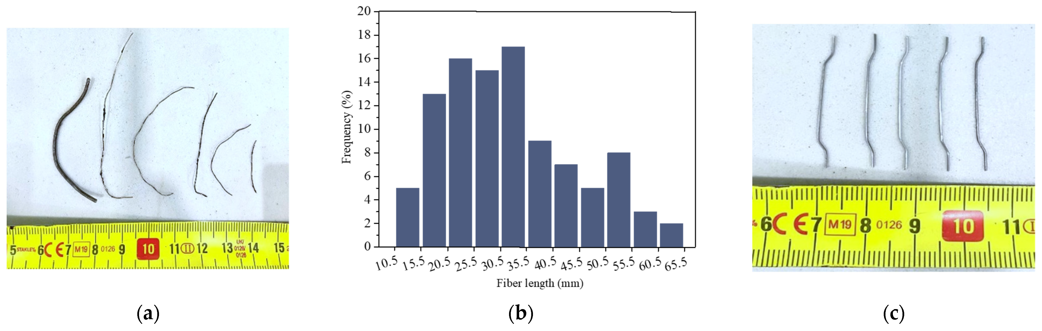
Pictorial descriptions of the RSF used in this study, illustrated as
Figure 1a,b, shows that RSFs are characterised by different diameters, lengths, and shapes. Overall, 100 RSFs were grabbed randomly, and the length and the diameter of each fibre was evaluated. The average diameter of the fibres was measured as 0.38 mm (CoV. 40%). The RSFs had the average length of 33 mm (CoV. 38%), and the mean aspect ratio of 91 (CoV. 40%). The frequency of the fibres with a certain length is represented in
Figure 1b.
The density of RSFs were generally considered equal to those of the ISFs (i.e., 7200 kg/m
3) in most of the published literature, since the RSFs were assumed free of impurity and tire rubber. Recently, Samarakoon et al. (2019) [
29] have evaluated the density of RSFs, finding the same average diameter and length of the RSFs used in the present research, being 3014 kg/m
3. This value is almost half of the ISF’s density, which refers to a higher number of RSFs in a unit volume of concrete compared to industrial types.
The adopted industrial steel fibres for tailoring the FRSCCs were hooked end steel fibres of 35 mm length, l
f, aspect ratio l
f/d
f of 64 (
Figure 1c), and tensile strength of 1395 MPa. The applied cement was CEM I 52.5 R, in accordance with EN 197-1 [
30]. The compressive strength of this cement at 3-days and at 28-days were reported by the company as 30 and 52.5 MPa, respectively. Limestone filler, biomass fly ash, a second-generation of superplasticizer based on polycarboxylate ether (PCE) polymers (Glenium SKY 617), tap water, and two types of aggregates (containing river sand and crushed granite with respectively grain size of 0–2 mm, and 2–12.5 mm) were the rest of material applied for developing the FRSCCs.
2.2. Mix Design Method
The mix design methodology proposed by Soltanzadeh et al. (2015) [
31] was adopted for the development of the FRSCCs. This method of developing concrete provides the possibility of tailoring concretes reinforced with high dosages of steel fibres that have rheological and mechanical properties suitable to produce precast/prestressed concrete elements–e.g., self-compacting character–and a relatively high compressive and post-cracking residual strength. Based on this method, a FRSCC with 90 kg/m
3 ISF was formulated as a reference concrete. Next, three different types of FRSCC including 90 kg/m
3 steel fibres were tailored by means of replacing the ISF at three weight ratios of 50%, 67%, and 100% using RSF.
For developing all the concrete mixes, first, the proportion of constituent materials were evaluated to make an optimized paste. Second, the optimum volume percentage of the aggregates as the granular skeleton of the concrete were assessed, and third, the correlation between the paste and the solid skeleton was optimized. An approximate slump flow [
32] of 600 mm was obtained by testing the flowability of all the concrete mixes. All the FRSSCs were designed to pertain to the C50 strength class for a reliable comparison of the concrete mechanical properties at the harden stage.
The adopted compositions of the developed concrete mixes are presented in
Table 1 and are nominated by the “FRSCC
Ri_Ij” label, where “
i” indicates the weight of the RSFs and “
j” implies the weight of ISFs applied for developing 1 m
3 of the FRSCCs. For instance, the hybrid FRSCC with 45 kg/m
3 ISFs and 45 kg/m
3 RSFs is identified as “FRSCC
R45-I45” in
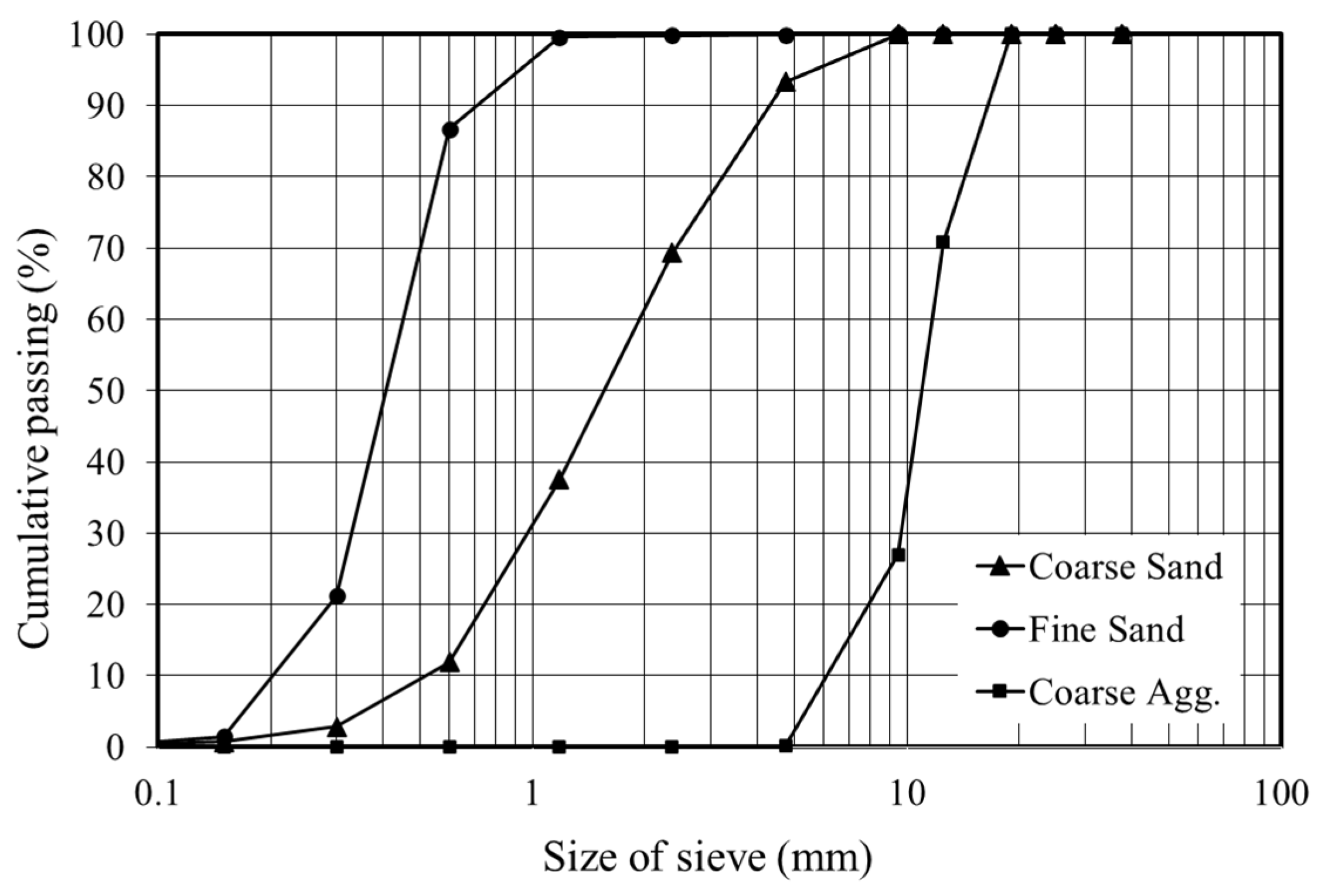
Table 1. Three types of aggregates–two containing fine and coarse river sand with maximum size of 2.4 mm and 4.8 mm, respectively, and one containing crushed granite with 12.5 mm maximum size–were adopted for developing the FRSCCs. The grading curves of the introduced aggregates is illustrated in
Figure 2. The concrete compositions were produced using a relatively high dosage of class F fly ash (with 81.15–94.40% particle size of <75 μm and 68.45–85.90% particle size of <45 μm) in order to significantly decrease the friction and the flow resistance of the paste.
Comparison of the concrete compositions, introduced in
Table 1, shows that the volume of paste to aggregate ratio was increased in the formulated FRSCCs containing RSFs. In fact, to establish a proper flowability in the tailored concrete reinforced by RSFs–with higher perturbation effect compared to the ISFs–it was necessary to increase the paste/aggregate ratios.
The mechanical performance of the developed FRSCCs were studied in terms of the compressive, flexural, and splitting tensile strength of the hardened concrete at the age of 28 days.
2.3. Compressive and Flexural Behavior
The elastic modulus—
Ecm [
33], and compressive strength—
fcm [
34], of the tailored FRSCCs were characterized using a total number of twelve cylindrical specimens (three specimens per concrete mix) of 150 mm in diameter and 300 mm in height, as presented in
Table 2.
As it was expected, based on the previous studies [
25], the fibre volume fraction did not significantly affect the compressive strength of the tailored FRSCCs. Despite a minor detrimental effect of 100% replacement of ISFs with RSFs, the compressive strengths of all the mixtures reached the target strength of 60 MPa. The marginally higher compressive strength of FRSCC
R0-I90 in comparison with that of FRSCC
R90-I0 can be attributed to the 10% decrease of the coarse aggregate volume and an increase of 9% in the paste volume of the FRSCC
R90-I0 to provide a suitable flowability and avoid the perturbation effect of the 90 kg/m
3 RSFs applied to tailor the FRSCC
R90-I0 composition. Reduction in the volume of coarse aggregate, which is regarded as the concrete skeleton, can influence the compressive strength of FRSCC
R90-I0. The higher perturbation in the skeleton organization of FRSCC
R90-I0 due to the application of the high content of RSFs compared to the other concrete compositions can be another reason for the marginally lower compressive strength obtained by testing FRSCC
R90-I0.
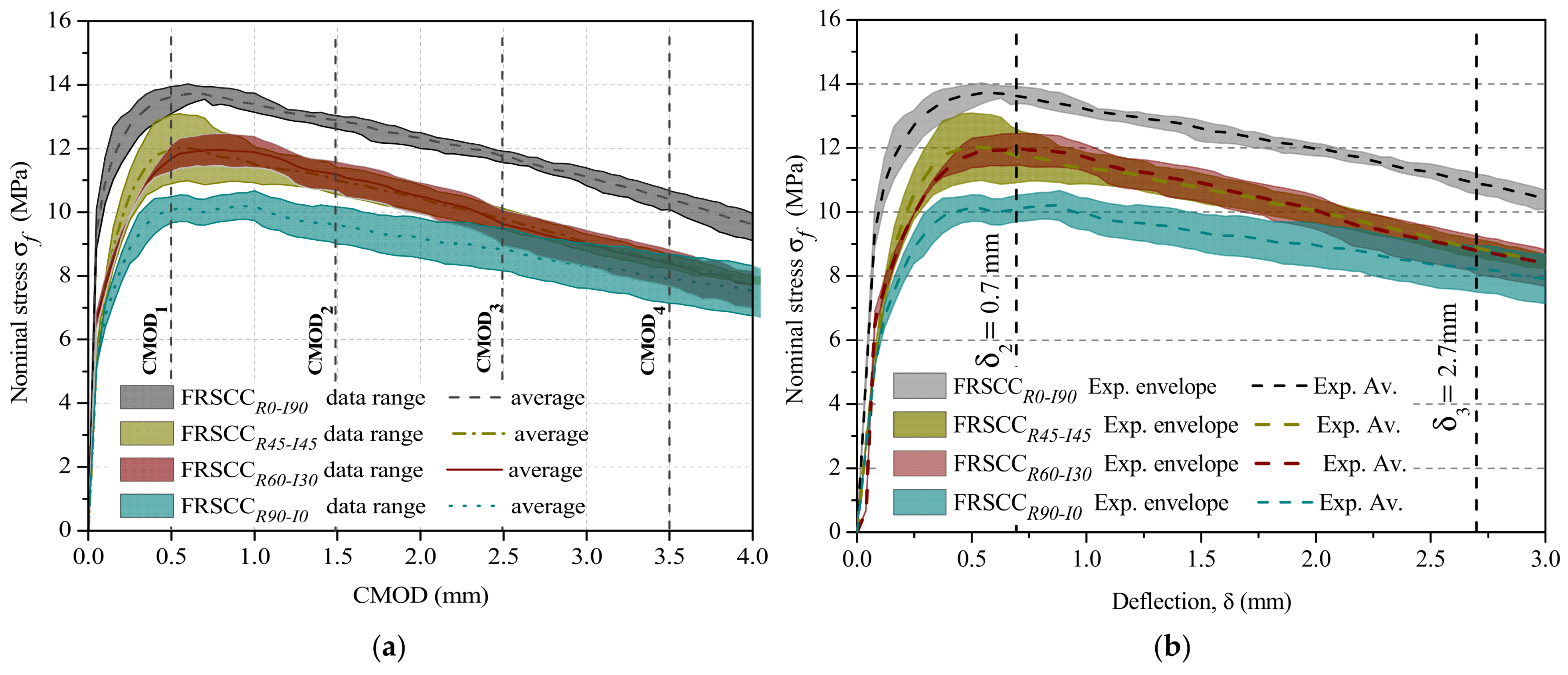
The flexural behavior of all the developed FRSCCs was evaluated by testing three notched prismatic specimens for each FRSCC, with a 150 × 150 mm
2 cross-section and 600 mm length under three-point loading conditions, as per RILEM TC 162-TDF [
35]. The nominal flexural stress—
, (the
, (where
P is the applied load, and
L,
b, and
hsp are the effective span, width of the specimens, and the depth of the notched cross-section of the specimens, respectively)–versus crack mouth opening displacement (CMOD) relationship of the developed concretes partially/totally reinforced by RSFs were compared with that of the reference concrete FRSCC
R0-I90, as shown in
Figure 3.
For comparison of the energy absorption capacity of each FRSCC, the average
versos midspan horizontal deflection (
) relationship of the specimens were presented in the same figure (see
Figure 3b). Based on RILEM TC 162-TDF [
35] recommendations, the energy absorption capacity of the developed FRSCC (D
BZ,3Ref) was calculated as the area under the load-deflection curve up to the deflection of
mm, where
mm in the present study.
Figure 3 shows that a reduction in the post-cracking flexural behavior and the energy absorption capacity of FRSCC occurred with the increase in the replacement dosage of ISFs by application of RSFs. In fact, after visible crack initiation of the matrix (at about 5 MPa), the ISF reinforcements used for developing the FRSCC
R0-I90 provided the more effective collaboration for increasing the flexural capacity of the concretes, with a higher energy dissipation compared to the RSF used for reinforcing FRSCC
R90-I0. The longer ISFs in FRSCC
R0-I90 activated as micro-cracks widened, which would have provided a higher degree of macro-crack bridging and fibre-pull-out resistance. The shorter length of the adopted RSFs compared to that of ISFs could be a reason for obtaining the lower post-crack strength, and consequently the lower energy absorption capacity in the concrete specimens totally reinforced with the RSFs (i.e., FRSCC
R90-I0) compared to that of the reference specimens. In FRSCC, the level of macrocrack bridging and post-crack load sustenance that could be supplied by ISFs of 35 mm length was not provided by the RSFs of a shorter length. However, both types of fibres (i.e., RSF and ISF) provided a ductile post-peak behavior up to 3 mm of CMOD. The residual flexural strength of the reference concrete produced by solely 90 kg/m
3 ISFs exceeded 13 MPa up to the crack width of 1.5 mm, whereas the replacement of 45, 60, and 90 kg/m
3 of ISFs with recycled fibres in developing the FRSCC caused a 13%, 13%, and 23% reduction, respectively, in the residual flexural strength of these concretes at 1.5 mm CMOD. The calculated D
BZ,3Ref for each of the developed concretes are also represented in
Table 3.
These results suggest that replacing 50%, 67%, and 100% of ISF dosage with the recycled fibres reduced the capacity of absorbing energy to 16%, 16.3%, and 26.4%, respectively. The reduction in the residual flexural strength and the energy dissipation of the FRSCCs produced by using RSFs can be due to the entangled shape of the RSFs applied for replacing the ISFs, which reduced the homogeneity of the fibre dispersion. Additionally, the higher compressive strength of the reference concrete may provide a stronger bond [
28] between the fibres and the matrix compared to the fibre/matrix bond in the case of the other tailored FRSCCs. Similarly, the difference between the flexural performance and therefore the energy absorption capacity of the two FRSCCs–i.e., FRSCC
R45-I45 and FRSCC
R60-I30–of the same compressive strength was found marginal.
Comparing the density of fibres distributed on the cross-section of the flexural specimens made of FRSCCR45-I45 and FRSCCR60-I30 has shown that FRSCCR60-I30, tailored by replacing a higher dosage of ISFs with RSFs, was reinforced with a higher total number of fibres. This could be justified by the much lower density of the RSFs compared to that of the industrial fibres. FRSCCR60-I30, which contains a higher number of shorter individual RSFs per unit volume of matrix (in comparison to FRSCCR45-I45), might provide a longer delay in micro-crack initiation and a more robust crack-bridging at the micro level as a result of the reduced fibre-to-fibre distance in the matrix.
FRSCCR45-I45 and FRSCCR60-I30, reinforced with both hybrid ISFs and RSFs, similarly have shown 18%, 15%, 11%, and 6% higher residual strength, respectively, at the CMOD1 to CMOD4 compared to that of the FRSCCR90-I0 produced solely by means of RSF reinforcements. The improved performance observed by application of hybrid IFSs and RSFs in tailoring FRSCCR45-I45 and FRSCCR60-I30 can be attributed to the multi-level crack stabilization and crack propagation control. In fact, compared to FRSCCR90-I0, the hybrid FRSCCs containing both shorter (i.e., RSF) and longer (i.e., ISF) fibres in their matrix have provided a more robust crack-bridging at the micro level and a better macro-crack bridging and fibre-pullout resistance at the level of macro-crack.
2.4. Splitting Tensile Behavior
2.4.1. Specimen Preparations and Test Setup
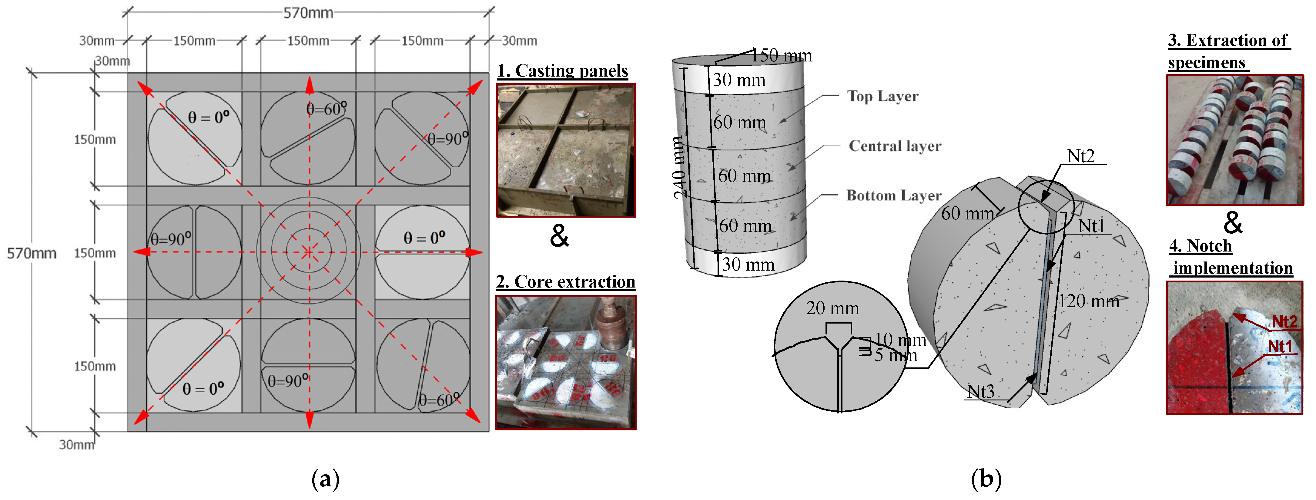
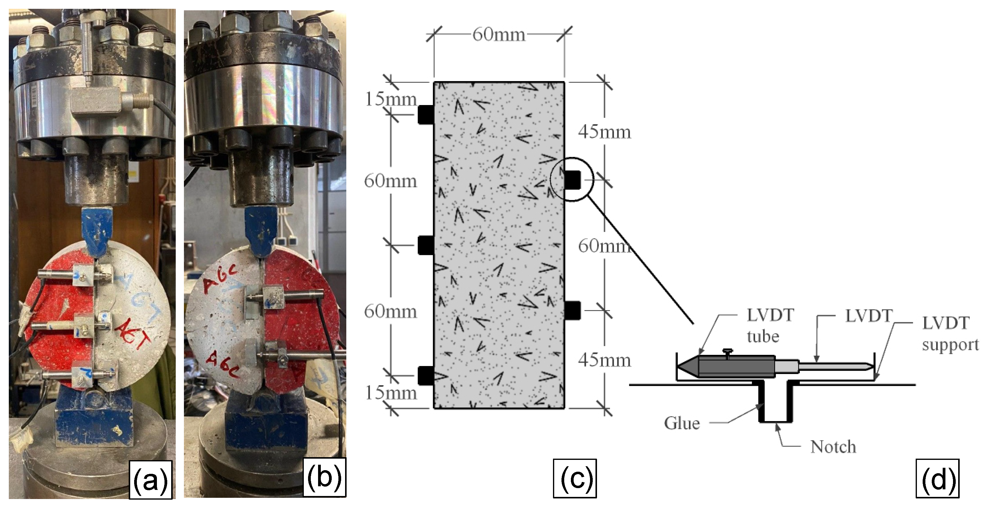
To produce the specimens, a concrete block was cast using each of the four developed FRSCCs from the center point (
Figure 4) to provide the possibility of orientating the fibres perpendicular to the radial flow direction. The blocks were measured as 570 × 570 mm
2 in plan with a 240 mm thickness, as shown in
Figure 4a.
The red arrows in the figure represent the direction of concrete flow during casting. The cast FRSCC blocks were demoulded after three days of being kept in the laboratory environment (with an average temperature of 21 °C and relative humidity of 60%), with the exposed face protected with a plastic film. After 28 days of casting, eight cylindrical cores of 150 mm diameter were drilled out of each concrete block. Three splitting tensile specimens of ϕ150 × 60 mm were produced using each of the extracted cores, as shown in
Figure 4b. Two notches of 5 mm depth, named as Nt1 in
Figure 4b, were executed on each opposite face of the specimens in order to localize the crack plane. The notched planes were executed at three different angles of θ = 0°, 60°, and 90° to the direction of concrete flow, as illustrated in
Figure 4a.
A total number of nine splitting tensile specimens with the notched plane parallel to the expected concrete flow (θ = 0°) were extracted from each block to evaluate the effect of replacing the ISFs with the recycled fibres on post-cracking behavior of the FRSCC. It is expected that at θ = 0°, the highest number of fibres have located perpendicular to the direction of the notched plane (compared to θ = 60° or 90°), since it is proven that the fibres are oriented orthogonally to the flux line [
36]. The rest of the extracted specimens (with 60° and 90° angle between the notched plane and the direction of the concrete flow) were used for the evaluation of the quantitative relationship between fibre orientation/distribution and the mechanical properties of the developed concrete. Results of the later investigation (i.e., evaluation of fibre orientation/distribution effect on the mechanical behavior of the FRSCC), which are beyond the scope of this article, are not reported in the present work, but the post-cracking behavior of the developing FRSCCs using different dosages of RSF/ISF (with 0° angle between the notched plane and the flow direction) is discussed in the next section.
A schematic representation of the adopted splitting tensile specimens is illustrated in
Figure 4b. This figure shows that in addition to the Nt1 notches executed on both surfaces of the specimens, a V-shaped groove with 45° inclination (notch Nt2) was implemented at the extremities of the notched planes in order to induce a stress field corresponding to an almost pure mode I fracture in the notched plane. An additional straight notch of 5 mm depth was presented at the vertices of each V grooves (notch Nt3). This notch assured the crack opening at the notched plane and moved the tip of the crack away from loading points with high stress concentration. All the produced specimens–with the N1 notch direction parallel to the direction of the concrete flow–were categorized in four groups according to the type of the adopted FRSSCs introduced in
Table 1.
The splitting tensile test setup was prepared in order to evaluate the relationship of load versus crack width along the fracture surface during the loading process based on the ASTM C-496 [
37] standard. The splitting test was conducted in closed-loop displacement control, using an external horizontal linear variable differential transducer (LVDT), positioned on the actuator to control the vertical deformation of the specimen. The load was applied on the top of the N2 notch by means of a 150 kN load cell. The displacement rate of 1.0 μm/s was adopted up to the displacement of 2.0 mm. Then, this rate was increased to 2.0 μm/s up to the end of the test. An accurate detection and tracking of the crack propagation was carried out using five LVDTs installed on the opposite surfaces (three on the front face and two on the rear face) of each specimen, according to the representation indicated in
Figure 5.
2.4.2. Results and Discussion
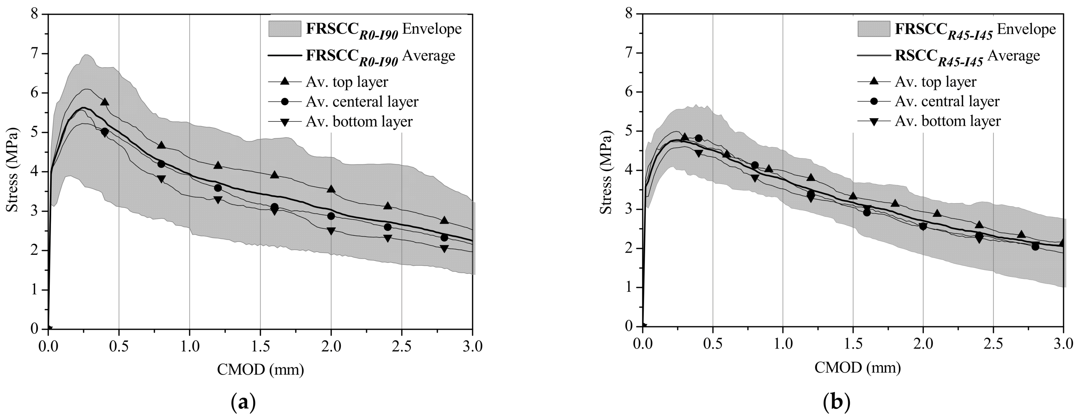
The average and envelope splitting tensile stress (
) versus crack mouth opening displacement (CMOD) relationship of all four groups of specimens is illustrated in
Figure 6.
The CMOD was computed as the average of the values measured in the five LVDTs installed in the splitting tensile specimen. The splitting tensile stress was calculated according to Equation (1), as proposed by ASTM C-496 [
37].
where
is the compressive load applied in the specimen,
l is the thickness of the net area in the notched plane (with the nominal values of 50 mm), and
h is the diameter of the FRSCC cylinder after executing the notches (equal to 120 mm).
By loading all the specimens, a small load decay was observed after crack initiation, which was followed by a slight strain-hardening branch. Compared to the results of testing the specimens solely reinforced by ISFs, a lower scatter was found in the stress-crack width response of the mono/hybrid RSF-reinforced concrete specimens. The scattering of the results can be attributed to local dispersion and orientation of fibres, as it has already shown by Soltanzadeh et al. (2015) [
31]. Counting the number of effective fibres crossing the fracture surface of the specimens has justified a fairly lower scattering of the results in case of mono/hybrid RSF-reinforced specimens, since the opening and propagation of the crack in case of FRSCC
R90_I0 (with the number of 250 average effective fibres, N
eff, and CoV.9%), FRSCC
R45_I45 (N
eff = 245, CoV.9%), and FRSCC
R60_I30 (N
eff = 241, CoV.17%) specimens, respectively, were controlled with a much higher number of fibres in comparison to that of the FRSCC
R0-I90 specimens (N
eff = 174, Cov.19%).
Figure 6 also compares the average stress–CMOD relationships of the specimens extracted from the top, central, and bottom layer of each FRSCC block (see
Figure 4b). The small differences between the results obtained by testing the specimens belonged to different layers indicate that fibre distribution and orientation was not too different along the depth of each concrete block due to the good equilibrium of flowability and viscosity. The average stress–CMOD relationships results of the specimens related to the three layers were found much closer to the
–CMOD relationship obtained by testing all the specimens of a relevant block, in case of the specimens extracted from respectively FRSCC
R45_I45 and FRSCC
R90_I0 and FRSCC
R60_I30 blocks. This could be another reason for obtaining a lower scatter by evaluating the stress-crack width response of the RSF-reinforced concrete specimens in comparison to that of reference specimens.
Despite the relatively high dispersion of the results observed in the case of
FRSCCR0-I90 specimens, among all the specimens the highest average maximum stress,
, and average post-cracking tensile strength was obtained by testing the ISF reinforced specimens. Replacing 50%, 67% and 100% ISFs by the recycled ones in developing FRSCC has reduced the
respectively 15%, 19% and 34%. However, a higher average fibre reinforcement density (i.e., ratio of
to the specimen’s fracture area “
”,
) of the mono/hybris RSF-reinforced concrete specimens (
) compared to that of the specimens made of FRSCC
R0-I90 (
) offered a more effective resistance to the cracking process and provided a smoother load decay after the peak load. Thus,
of FRSCC
R0-I90 specimens reduced 30% at a crack width of 1 mm, whereas the lower decay of 21%, 23%, and 17% was evaluated for the FRSCC
R45_I45, FRSCC
R60_I30, and FRSCC
R90-I0 specimens, respectively, at the same crack width (see
Table 4).
This can be attributed to pull-out behavior of the RSFs, which were affected by the geometry of the fibres as well as the amount of rubber attached to the fibre surface. It is already shown [
20,
38] that RSFs with more irregular and twisted embedded lengths collaborate significantly to provide a higher fibre pull-out load and greater probability of fibre rupture. However, the smooth load decay observed during the post-cracking of the RSF-reinforced concrete specimens has demonstrated that the failure of specimens mostly occurred by the pull-out of the fibres, and the number of broken fibres during the splitting tests was not significant. Regarding the amount of rubber attached to the fibre surface, it should be noted that generally the fibre pull-out strength decreases with the increase of rubber content on the surface of the RSFs [
19]. Taking into account that the average stress at crack initiation and the average post-cracking tensile strength have decreased by increasing the replacement dosage of ISF using RSFs, it is possible to derive that some rubber debris attached to the surface of RSFs affected the splitting tensile behavior of the RSF-reinforced concerts. The rubbers caused a lower level of pull-out load for the RSF-reinforced concrete specimens, which may justify the lower average splitting tensile stress compared to that obtained by testing the reference specimens.
The residual strength parameters (
) and the absorbed energy during the fracture process (
) at a certain crack width “
” (represented by the area under the softening curve up to
) were also computed for all the specimens and presented in
Table 4. This table shows the reduction of residual strength and consequently the energy absorbed by increasing the dosage of RSFs in developing the FRSCCs. For instance, the average residual strength obtained by testing the reference specimens at a crack width of 1mm was reduced to 4%, 11%, 23% by replacing 50%, 67%, and 100% ISFs by RSFs, respectively, in developing FRSCC. This reduction in the residual strength led to the relevant absorbed energy being reduced by about 10%, 14%, and 28%, respectively, at
= 1 mm. A similar justification has been drawn for the lower stress versus crack opening relationship observed in the case of RSF-reinforced concretes compared to the reference concrete, and can explain the reduction in the residual strength and the respective energy due to fracture propagation at the specific crack width.
To identify the more effective fibres and their best dosage for developing FRSCC, it is of paramount importance to take into account the environmental impact of the developed concrete in addition to the mechanical performances [
29,
39]. In the present study, an eco-mechanical approach was adopted to evaluate the potentiality of RSFs for replacing the ISFs in tailoring the FRSCCs by considering both environmental and mechanical performances. Therefore, the environmental impacts of the developed concrete were evaluated in the next section through a LCA.
3. Life Cycle Assessment (LCA)
In this study, a LCA was performed, as per the international standards ISO 14040 [
40] and ISO 14044 [
41], to evaluate the environmental impact of the developed concretes using RSFs and/or ISFs. As previously mentioned, the present research is an attempt to evaluate a novel solution for limiting new material extraction (while retaining the long-term economics of the extracted materials) and reduce the residual waste. A “cradle-to-gate” system boundary was adopted in this study, as the LCA was focused on the circular economy in construction [
42,
43]. This system boundary included estimating all emissions and energy consumptions by extraction of raw materials (i.e., the cradle), processing (cement, ISF, RSR, fly ash, limestone, sand, superplasticizer, and aggregates), and transporting the materials, and finally mixing the FRSCC compositions (i.e., the gate), as shown in
Figure 7. The functional unit was considered as 1 m
3 of FRSCC, which is the basis for comparison throughout
Section 3 and
Section 4.
3.1. Life Cycle Inventory
A detailed inventory was created in order to answer the simple question of “how sustainable is the RSF-reinforced concrete throughout its life cycle?”. This phase of LCA, i.e., providing a life cycle inventory, was carried out by means of compilation and quantification of inputs (e.g., energy and materials) and outputs (e.g., emissions and wastes) of the concrete production system, based on the data drives from on-site survey as well as the average data provided by one of the most internationally accredited generic environmental databases [
44]. The inventory of the materials considered for developing 1 m
3 of each of the formulated FRSCCs is the same as those presented in
Table 1. The assigned transportation to each of the introduced materials, as well as the summarized life cycle inventory sourcing, is presented in
Table 5.
For transportation processes, the distances between the places of raw material extraction/storage in Portugal and the concrete mixing plant located at the Laboratory of Structures (LEST), which belongs to the Department of Civil Engineering at the University of Minho, Portugal, was taken into account. The additional details related to the production, procedure, and transportation of the compositions used for tailoring the FRSCC are addressed as follow:
High-performance cement, CEM I 52.5 R, produced at a Portuguese cement plant, was delivered from Porto district, Portugal, to the LEST. The potential environmental impacts of the adopted cement were quantified by considering the inventory listed in the most recent public Environmental Declaration [
45] published by the cement plant.
The distance between the cement plant and the LEST was estimated to be 70 km, based on the Google Maps® application. The cement transportation was modeled using a diesel driven truck of 28–32 t payload capacity (GLO: Truck, Euro 5). The truck was fueled with diesel using the process “EU-28: Diesel mix at filling station ts”. The described choices for the fuel and truck were also set as default option for the limestone filler, fly ash, all types of aggregates, superplasticizer, and industrial/recycled discrete steel fibres.
Biomass fly ash was collected from a biomass co-generation plant in a pulp and paper industry, located in Vila Velha de Ródão municipality, Portugal. The fly ash was considered as a waste, without economic value, and no flows were allocated for its production [
40]. Thus, only the impact of transportation from Vila Velha de Ródão to the LEST (290 km distance) was attributed to fly ash.
Industrial Steel Fibres (ISFs) used in the present study was provided by a company located at Porto district in the north of Portugal. Life cycle inventory for the ISF is not available in the GaBi database. Thus, the potential environmental impacts of the applied ISFs were quantified by considering the data presented in the last environmental declaration published by a multinational steel manufacturing corporation [
47]. This environmental declaration transparently communicates the environmental performance of the ISFs, though electricity for production was not assigned to a specific country. Therefore, the results of the environmental declaration were advanced in the present work by accounting the electricity grid mixes of Portugal (PT: Electricity grid mix 1–60 kV) in the calculations. The Portuguese energy mix was also set to the default option in LCA of the RSF and mixing the compositions to develop FRSCCs.
Recycled steel fibres (RSFs) were collected from Porto district and transported for 30 km to the LEST. The RSF was produced according to the procedure described in
Section 2.1 at a national tire recycling company in the north of Portugal. The process of transporting the end-of-life tires to the municipality was excluded from the system boundaries due to lack of the data in this regard. As the RSFs are the waste material, they do not afford an economic value. Therefore, no flows were allocated to the production of the fibres. Based on the information provided by the company, the company consumes 165.2 kWh electricity to produce 1 ton of its product, including RSFs, rubber granules, and fluffs. To produce 1 ton of the product, the company uses 750 kg liquid nitrogen, which is transported (200 km) to the company by a diesel driven truck of 28–32 t payload capacity. The process of producing RSFs is displayed in a simplified way in
Figure 7 within the boundary marked in red color. This process was included in the LCA analysis of the FRSCCs made of hybrid and/or mono RSFs.
The generic data was adopted for life-cycle inventory of the other applied materials–i.e., limestone filler, gravel, sand, water, and superplasticizer–for developing the FRSCCs, as the comparison of different design scenarios for reinforcing the concrete using RSF and/or ISF is of the main goals of the LCA in the present work, and this can be carried out based on this generic/average data [
48].
3.2. Impact Assessment
In the impact assessment stage of the LCA, effects of emissions identified and quantified in the inventory for producing one cubic meter (i.e., the functional unit) of each FRSCC are evaluated, in several environmental impact categories (EICs). The emissions are classified into environmental loadings. The environmental loadings are then multiplied by characterization factors to give a single valuation representing the potential effect of the relevant environmental impact category (EIC) on the ecosystem (Equation (2)). Using the EIC indicator facilitates the comparison between environmental impact categories.
where (
EIC indicator)
i stands for the indicator value (per functional unit) for
i-th environmental impact category,
Ej identifies the release of emission “
j” (classified under the
i-th environmental impact category) per functional unit, and
CFi,j is the characterization factor for emission “
j” contributing to
i-th environmental impact category.
In the present study, the environmental impacts were determined with GaBi 6 software, with the possibility of selecting an impact assessment method out of several methods, including the midpoint method “CML 2001” [
49]. The impacts were quantified using CML 2001 impact assessment methodology due to the sound scientific basis of this approach, as well as its relatively wide range of emission- and resource-related impact categories available, and the reputation of the CML 2001 method within the scientific community. The environmental performance assessment was carried out based on the following six environmental impact categories from those of the CML 2001 approach, which are easily communicated and representative of the major environmental impact concerns [
50,
51,
52,
53]: (i) Global Warming Potential, GWP; (ii) Acidification Potential, AP; (iii) Eutrophication Potential, EP; (iv) Abiotic Depletion Potential for Fossil Resources, ADP; (v) Ozone Depletion Potential, ODP; (vi) Photochemical Ozone Creation Potential, POCP.
After calculating the environmental impacts associated with the development of each concrete on the ecosystem, the environmental impact category indexes were weighed and normalized using the following equation [
54]:
where
is the non-dimensional environmental score for RSF-reinforced concrete alternative
k,
i is the number of environmental impact category, and
is the weighted and normalized score of environmental impact category of
i for the alternative
k:
where
is the raw score of an environmental impact category as per functional unit of
VFS,
is the importance weight for the impact category
i,
m = 3 is the number of RSF-reinforced concrete alternatives. The symbol
denotes a function identifying the maximum value of the series.
3.3. Interpretation
The quantified values of the potential environmental impacts related to the production of 1 kg of different types of steel fibres applied in developing the FRSCCs, i.e., ISF and RSF, are presented in
Table 6. It is evident from the results that the environmental impacts of developing ISFs were much higher, specifically regarding ADP and GWP. These results highlighted the benefits of applying the RSFs in developing a more environmentally friendly concrete.
The environmental impacts of developing 1 m
3 of the tailored concretes reinforced by the RSFs and/or ISFs is comparable in
Table 7.
As expected, (by considering the results of analyzing the emissions resulted by producing 1 kg RSF and ISF) tailoring of the reference concrete FRSCCR0_I90 (solely reinforced by means of ISFs) caused the development of the highest environmental impacts in all the categories. The environmental impacts of producing FRSCC have reduced by increasing the RSF dosage as the replacement of the ISFs. Thus, the lowest environmental impacts were quantified for FRSCCR90_I0 composition. The lowest environmental impact category for the development of FRSCCR90_I0 among all the quantified concretes came from the POCP, which was produced due to the relevant transportations. The POCP impact of producing 1 m3 FRSCCR90_I0 was quantified as a negative value, because of the NO emissions that occurred during the transportation processes. According to CML 2001, the NO emissions have a negative characterization factor, which caused the transports to appear with negative POCP values.
By comparison, with the FRSCC compositions formulated in the present study (
Table 1), it should be noted that the ratio of paste to granular skeleton of the concrete compositions was increased slightly depending on the applied dosage of RSFs (compared to the reference concrete) to provide an almost similar flowability for all the mixes, and to disperse the RSFs uniformly in a concrete mix. Although application of a higher amount of the concrete paste in the case of mono or hybrid RSF-reinforced concretes led to the use of a higher dosage of cement and superplasticizer (which are respectively responsible for the development of the highest proportion of GWP and ADP among all the adopted compositions) [
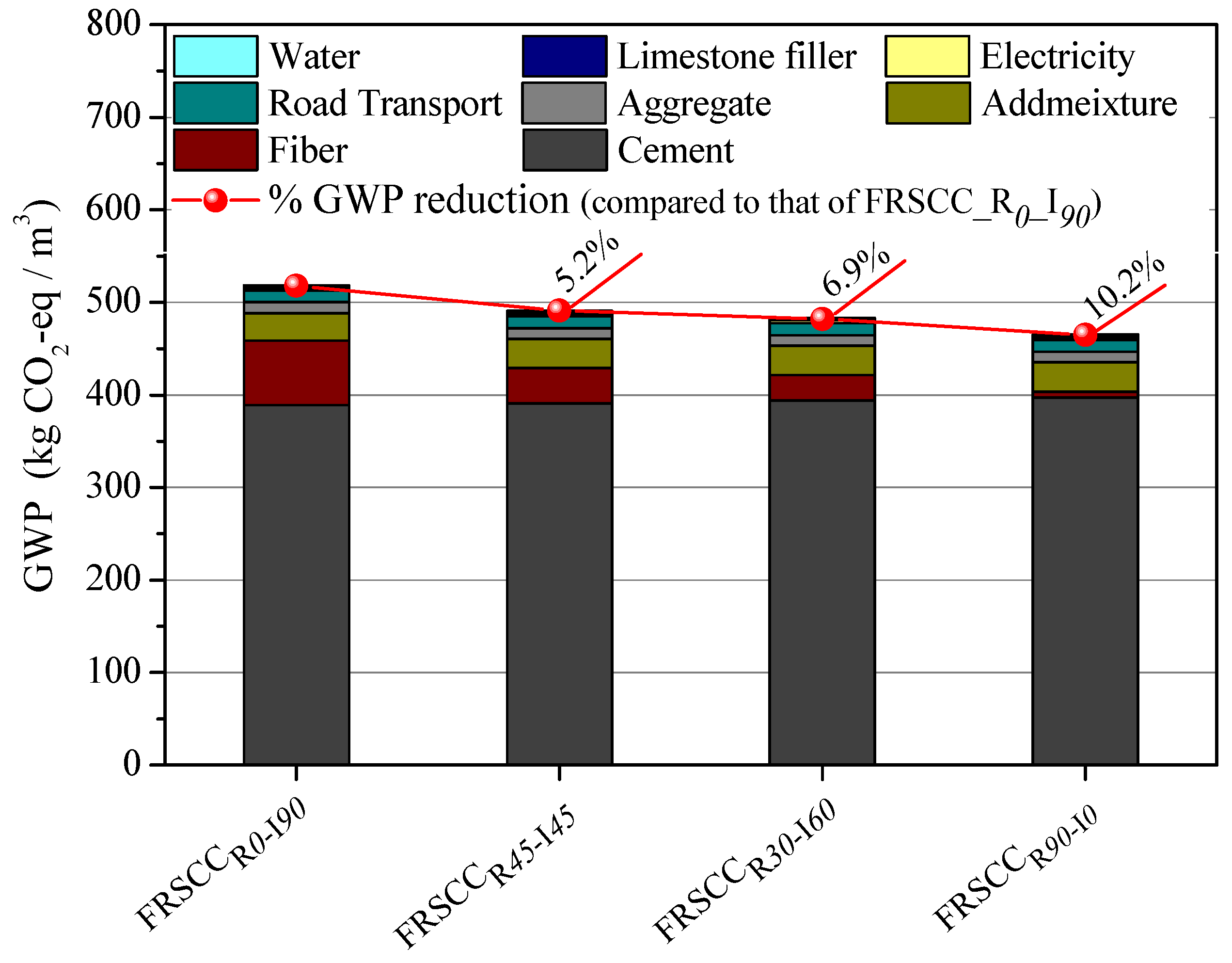
39], the potential environmental impacts of developing these concretes have still decreased. For instance, replacing 50%, 67%, and 100% of the ISFs with the recycled fibers to develop FRSCC reduced GWP impacts by 5%, 7%, and 10%, respectively, in comparison with that of the reference concrete, FRSCC
R0_I90. The ADP impact was reduced up to 23%, 31%, and 47% by means of replacing 50%, 67%, and 100% of the ISFs with the RSFs, respectively.
Figure 8 compares the amount of greenhouse gas emissions (i.e., those produced by the development of the concretes reinforced using ISFs and/or RSFs) by representing the breakdown of GWP, one of the highest impact category along the supply chain of concrete production. This figure indicates that the main source of emissions in the reference concrete, FRSCC
R0_I90, was associated to the cement application (75%), followed by embodied emissions from production of ISFs (13.4%), and admixture (5.7%), road transport and sand quarrying (both 2.4%), and electricity generation (0.61%). Substituting the relatively high dosage of ISF (i.e., 50%, 67%, and 100% of ISF) by the more sustainable fibres (i.e., RSFs) in developing FRSCC improved the environmental performance of the concretes. The main source of greenhouse gas emissions in the RSF-reinforced concretes was respectively related to application of cement (79% to 85%), admixture production (6.4% to 6.9%), producing ISF and/or recycling scrap tire fibres (1.3% to 7.7%), road transport (2.6% to 2.8%), sand quarrying (2.3% to 2.35%), and electricity generation (0.63% to 0.66%).
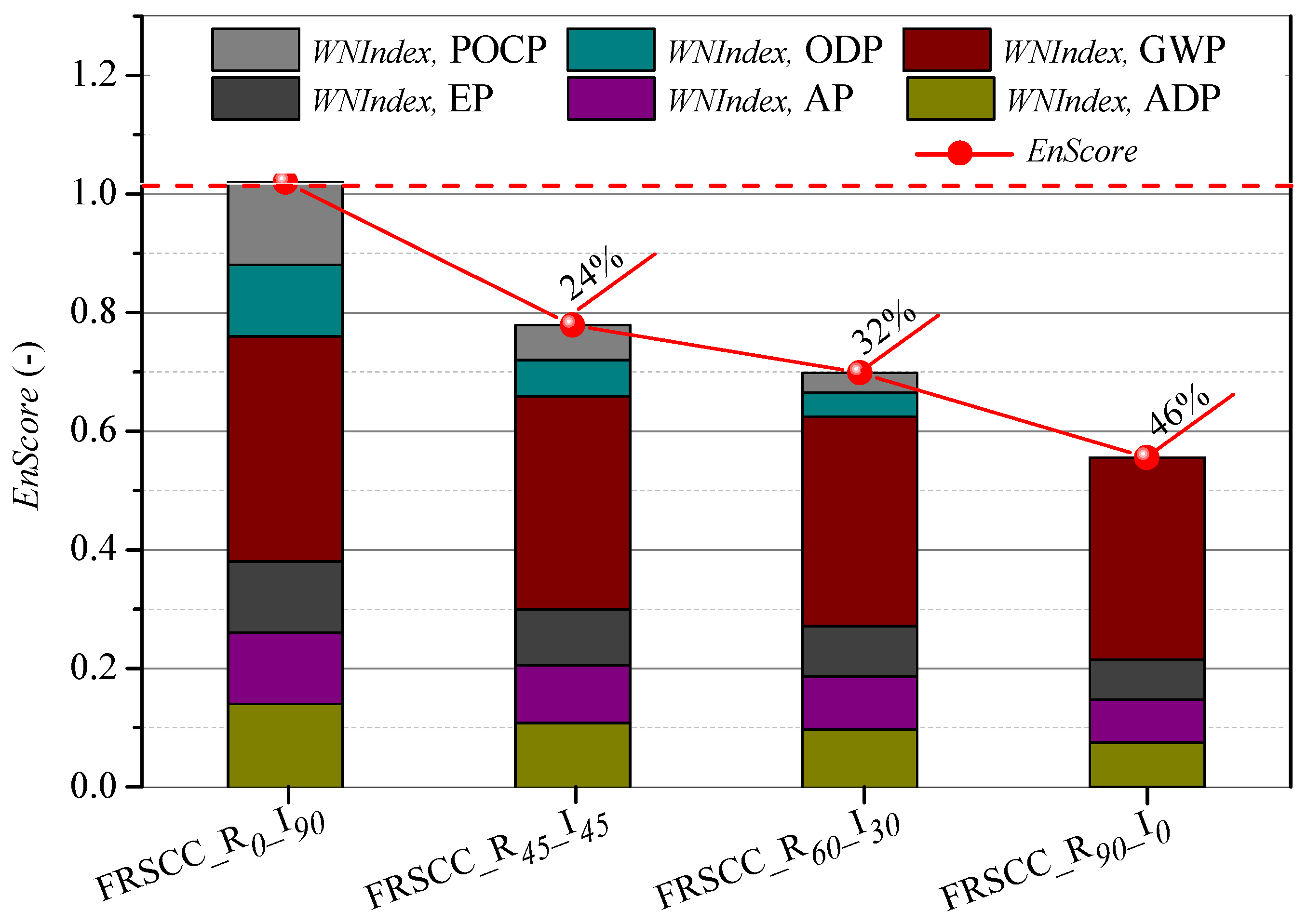
Comparison of the results of the environmental score, represented in
Table 7 and detailed in
Figure 9, has shown that replacing 50%, 67%, and 100% of the ISF with RSF in developing FRSCC reduced the
up to 24%, 32%, and 46%, respectively. This is due to the share of the weighted and normalized score of all the environmental impacts,
, being reduced by the application of relatively high dosages of RSFs to reinforce the concretes, as shown in
Figure 9. The total replacement of ISFs with that of recycled fibres provides the possibility of suppressing the POCP and ADP. The
calculated for ADP, AP, and EP were also reduced up to 47%, 39%, and 44%, respectively, by using FRSCC
R90_I0 Composition.
In general, replacing the ISFs with the recycled fibres for reinforcing concrete has great potential to produce a FRSCC with lower environmental impacts. However, a trade-off exists between a decreasing environmental impact associated to the reduction of ISF application (see
Figure 9) and the consequent decreasing of the mechanical performance of FRSCC (see
Figure 3 and
Figure 6). Thus, in the next section, the two competing factors of environmental performance and mechanical behavior of the developed FRSCCs is considers simultaneously.
4. Consolidated Environmental and Mechanical Index
In the present section, the simultaneous mechanical and environmental performances of each developed FRSCC (
EMk) were evaluated, based on the formula proposed by Khodabakhshian et al. (2018) [
54], as follows:
where
is the consolidated index of mechanical and environmental performances of the FRSCC composition alternative
k.
and
are the normalized environmental score and normalized energy absorption capacity of the alternative
k, respectively.
and
can be calculated using Equations (6) and (7), respectively. In these two equations,
m is the number of concrete mix alternatives.
In general, the high tensile/flexural behavior of FRC and its superior ductility and energy absorption capability under bending load make the FRC different from conventional concrete, which is accompanied by brittle failure [
55]. Therefore, the ductility-related measurements–such as post-cracking flexural capacity and energy absorption—of the FRC as the most relevant indicators of mechanical performance of fibrous concrete [
56,
57,
58] are of great importance for the design, construction, and safety evaluation of engineering structures.
Based on the above reasoning, energy absorption capacity, characterized by performing three-point bending test, was selected in this study as the measure of FRSCC mechanical performance. As the energy absorption capacity is one of the most important criteria for the performance evaluation of FRSCC, a similar weight coefficient was considered in the calculation of both the and indexes.
Results and Discussion
The results of evaluating both the normalized environmental and mechanical indexes for all the FRSCCs are presented in
Figure 10. From the figure, it is clear that an increase in the substitution dosage of ISFs led to a downward trend of the indexes. The reduction of
EnScoren occurred in a much higher rate in the case of the FRSCCs reinforced with more than 50% RSFs. This shows a superior environmental performance of the concretes tailored by replacing 67% and 100% ISFs with FSRs (i.e., FRSCC
R90_I0 and FRSCC
R60_I30) compared to the rest of FRSCCs. Compared to FRSCC
R45_I45 composition, FRSCC
R60_I30 has shown an 8% lower
EnScoren, with an almost equal
Mecn index. Thus, replacing 67% of ISFs with recycled fibres can be introduced as the optimum dosage when tailoring a hybrid RSF/ISF-reinforced concrete.
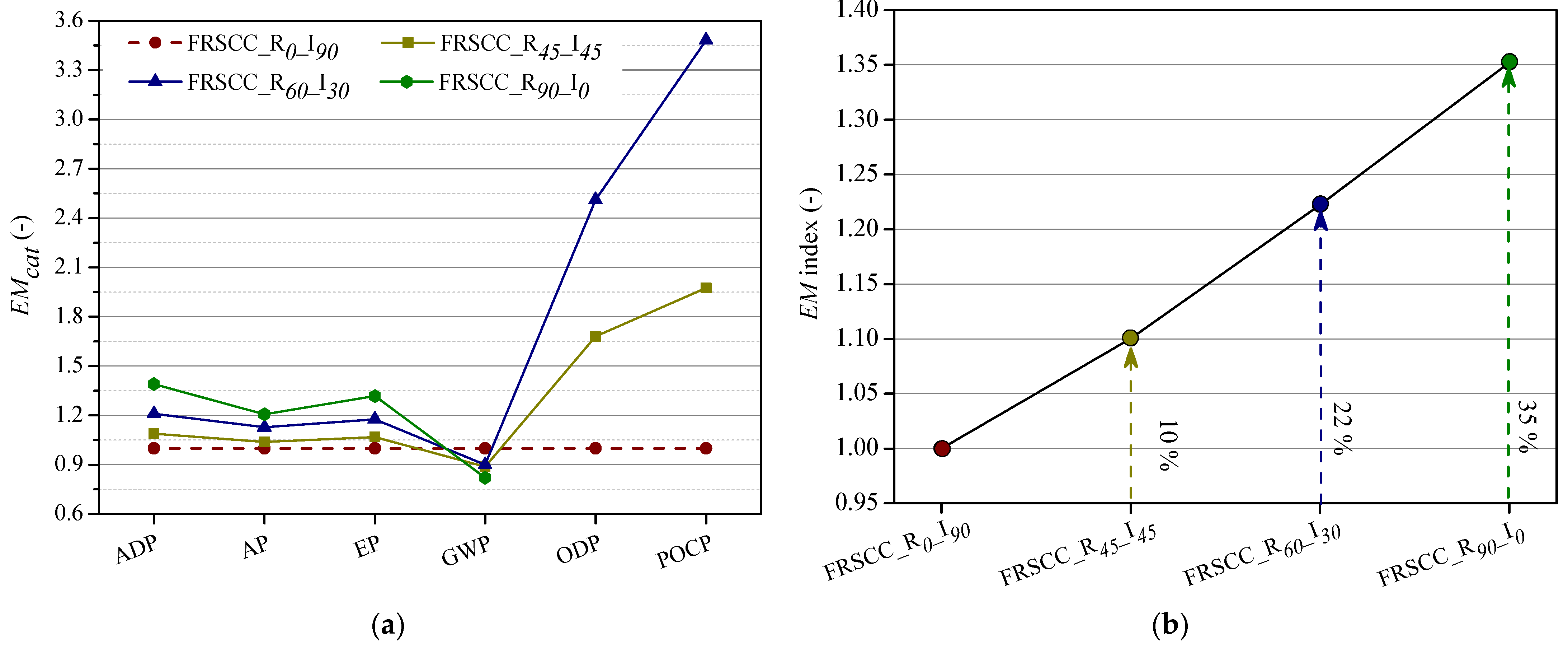
The values of consolidated index,
, for all the concrete compositions are depicted in
Figure 11. This figure also introduces the consolidated index values for RSF-reinforced concrete alternative
k, by considering each of the environmental categories,
, where
cat = GWP, AP, EP, ADP, ODP, POCP. By considering the results represented in
Figure 11a, it is clear that all
indexes, with exception of the one related to GWP, were increased by the replacement of ISFs with recycled fibres to reinforce the concretes. The RSF-reinforced concrete compositions, FRSCC
R45_I45, FRSCC
R60_I30, and FRSCC
R90_I0, have shown 16%, 16.3%, and 26% lower energy absorption capacity, respectively, in comparison to that of the reference concrete, FRSCC
R0_I90. Therefore, a lower normalized mechanical score,
, was calculated for the RSF-reinforced concretes compared to that of the reference concrete. On the other hand, the reduction in GWP impact by increasing the replacement dosage of ISFs was not as high as that calculated in the case of the other impacts (see
Figure 8), since using the RSFs slightly increased the required amount of cement in the development of the FRSCCs (to facilitate the homogeneous dispersion of the fibres). Consequently, the changes in the quantified
(
EM calculated by accounting only GWP impact) for the FRSCCs was marginal.
Although the RSF-reinforced concretes have shown the lower capacity in absorbing energy compared to that of the reference concrete, substitution of ISFs with the recycled ones has still provided an improvement in the consolidated index,
, of the developed concretes, as shown in
Figure 11b. For instance, replacing 100% of the ISFs with the recycled fibres resulted in a 46% reduction in
EnScoren, while the normalized mechanical index,
Mecn, was reduced by 26%. Thus, FRSCC
R90_I0 has shown a 35% higher
in comparison to that of the reference concrete. Application of 100% RSFs in the development of concrete decreased the major impact of producing FRSCC, related to the extraction of elements and fossil fuels (i.e., ADP), by 47% (see
Table 7), and thus provided a 39% increase in EM
ADP. Using FRSCC
R90_I0, the environmental impacts related to AP and EP were reduced up to 40% and 44% (in comparison with the reference concrete), respectively, and led to improve the EM
AP and EM
EP values by 20% and 32%, respectively. Application of RSFs instead of industrial fibres has also provided the possibility of almost eliminating the ODP and POCP impacts in the production of FRSCC
R90_I0. The results illustrated in
Figure 11 confirm the high eco-mechanical efficiency (the eco-friendlier concrete with acceptable mechanical performances) of the mono/hybrid RSF-reinforced concretes developed in the present study compared to that of the reference concrete produced solely using ISFs. As aforementioned, the FRSCC
R90_I0 provided the highest consolidated index,
, among all the FRSCCs, and can be selected as the most eco-mechanical efficient concrete.


