
Automation and Remote Control of an Aquatic Harvester Electric Vehicle
by
 , , , and
Emil Tudor
1,* ,
,
Mihai-Gabriel Matache
2,
Ionuț Vasile
1,
Ion-Cătălin Sburlan
1 and
Vasilica Stefan
2 1
National Institute for Research and Development in Electrical Engineering, 030138 Bucharest, Romania
2
The National Institute of Research—Development for Machines and Installations Designed for Agriculture and Food Industry—INMA Bucharest, 013811 Bucharest, Romania
*
Author to whom correspondence should be addressed.
Sustainability 2022, 14(10), 6360; https://0-doi-org.brum.beds.ac.uk/10.3390/su14106360
Submission received: 20 April 2022
/
Revised: 17 May 2022
/
Accepted: 20 May 2022
/
Published: 23 May 2022
(This article belongs to the Special Issue Mobility Sustainability: Ecological, Smart and Connected Transportation Systems)
Abstract
:Electric boats are evolving, following the trend of imposing electric powered vehicles in all transportation solutions. For a research project, a reed and aquatic weed harvester, the author’s goal is to develop an experimental electrical vehicle aimed at solving several particular problems such as: small speed, big throttle, high maneuverability, big load capacity, small draught and affordable cost. The solution comprises of one electric motor powered by a converter supplied from Li-Ion batteries, which drives a hydraulic pump for simultaneous operation of two lateral-placed paddle wheels and one complex mechanism of cutter and conveyor. The control system of this vehicle consists of one remote controller, with bidirectional radio communication to three on-board controllers used for the management of the electro-hydraulic actuators, the electric motor and the battery storage system. The hardware and the software architectures are presented, underlining the automated operations designed to increase the safety, the maneuverability and the predictability of the vehicle. The advantages of the use of control electronics is the increasing operability of the vehicle by supervising the available stored energy and the predicted consumption of energy, the fast and remote assistance in case of operational failure using online diagnose and the operation optimization by selecting the best load profile for the cutter and for the paddles. The results of this research are the validation of the proposed hardware and software architectures used for the control of an electro-hydraulic vehicle and the feasibility of using radio communication and remote diagnose for vehicle control.
1. Introduction
Aquatic plants serve as a vital component to the overall health of the aquatic environment. There are numerous plants that grow in farm dams, streams and waterways and most of the times they are rarely considered a problem.
However, when water becomes rich in nutrients aquatic plants can grow vigorously to a point where they actually can become harmful to the rest of local vegetation and animal life [1,2].
- cover the entire water surface, causing oxygen depletion;
- as introduced species, compete with native species and reduce biodiversity;
- have an impact on the aquatic habitat of bird species and cause them to relocate;
- interfere with commercial and recreational activities;
- cause blockages or impede water intake to pumping equipment.
The main way to remove unwanted aquatic biomass is mechanical removal which involves the removal of the plants from the water body using specially designed harvesters or equipment. Mechanical harvesting, however, can be difficult in and around overhanging trees and can be expensive to implement.
Advantages of mechanical harvesting [3]:
- the habitat remains intact because most harvesters do not remove submersed plants all the way to the lake bottom;
- mechanical harvesting is site-specific because plants are removed only where the harvester operates;
- no herbicide is used;
- utilization of harvested biomass is thought by many to be a means of offsetting the relatively high costs and energy requirements of mechanical harvesting.
Disadvantages of mechanical harvesting
[3]:
- demand for aquatic weed harvesters is very small, so the equipment associated with these operations is often custom-made and expensive;
- the area that can be harvested in a day depends on the size of the harvester, transport time, distance to the disposal site and density of the weeds being harvested;
- mechanical harvesters are not selective and remove native vegetation along with target weeds;
- regrowth of cut vegetation can occur quickly;
- floating plant fragments produced during mechanical harvesting can be a concern because most aquatic weeds can regrow from even small pieces of vegetation;
- disposal of harvested vegetation can be an expensive and difficult problem after mechanical harvesting;
- some lakes or rivers may not be suitable for mechanical harvesting. If there is only one public boat ramp on a lake and it is not close to the area to be harvested, the costs of moving the cut vegetation from the harvester to shore will add significantly to the cost of the operation.
The literature doesn’t cover very much the subject of aquatic harvester design, however there are a lot of research papers concerning aquatic biomass recovery, because biomass conversion can produce useful substances or fuels: bio-fuels [4], Bio-hydrogen [5], ethanol from cellulose [6,7], MeHg control [8], matter and energy flow across ecosystem boundaries [8], bio-hydrogen production analysis [9,10,11].
There are however some papers that deal with harvester design and which are referenced in [12,13,14,15]. Reference [13] describes the design procedure for a 1.6 kW water hyacinth harvester claiming an efficiency of 54.8%, in [14] a 750 W harvester was designed with an operating time of up to 1.5 h and a harvesting speed of 1200 m2 per hour, the authors used a 1 kW DC motor to control the paddles and 12 V battery system to supply power to the electrical components, [15] focused on the design of the fork and cutter devices, powered by a 150 W AC motor, they presented detailed mechanical calculations and 3D drawings, finally [16] presents stress analysis of the different parts of a harvester equipped with a 2 kW AC motor powered from a DC voltage source of 48 V. A patent was also found [17], for a 1.5-m electric harvester powered from a 48 V, 32 Ah battery, however very few details are given regarding the design or actual performance of the machine.
As part of an ongoing research project concerning aquatic biomass recovery, the authors present in this paper the electrical design of an aquatic harvester equipped with an AC motor powered by lithium batteries that is controlled using a remote controller via radio transmission.
This solution solves problems such as:
- -
- reduced costs—the main advantage of the solution proposed is the modular design that is meant to reduced cost, as the end user can simply go and replace components such as the electric motor, the power converter or the batteries to suit he’s needs, this main advantage is given by the control system of the harvester which is independent of the choice of these equipment’s;
- -
- no gas emission when compared to harvesters with diesel engines, the harvester is fully electric, having a AC motor powered from batteries;
- -
- it removes the need for extra equipment to store the aquatic biomass since the harvester itself has space for storage and is sufficiently large to be able to be used for lakes and other water surfaces clean-up, but is small enough that it can also be easily transported to other locations by using a trailer platform;
The authors present the hardware and software solutions for automatic control of each subsystem of the harvester (motor, converter, battery, hydraulics), with each individual unit responding to a master controller that supervises the entire system, ensuring reliability and safety. The user controls the entire system with a remote controller that has all the necessary control and diagnostic functions to operate the platform.
2. Materials and Methods
The automation refers to the fact the harvester receives commands from the remote controller, it validates the commands internally by software means, it performs an internal diagnostic of the system status, it executes the commands if they are correct and reports the updated status of the system. All these operations are automated and are independent from the user point of view.
The remote control refers to the fact that the harvester receives commands by means of radio communication from a distance, which is important when the harvester is operating on lakes or similar.
2.1. Hardware Development
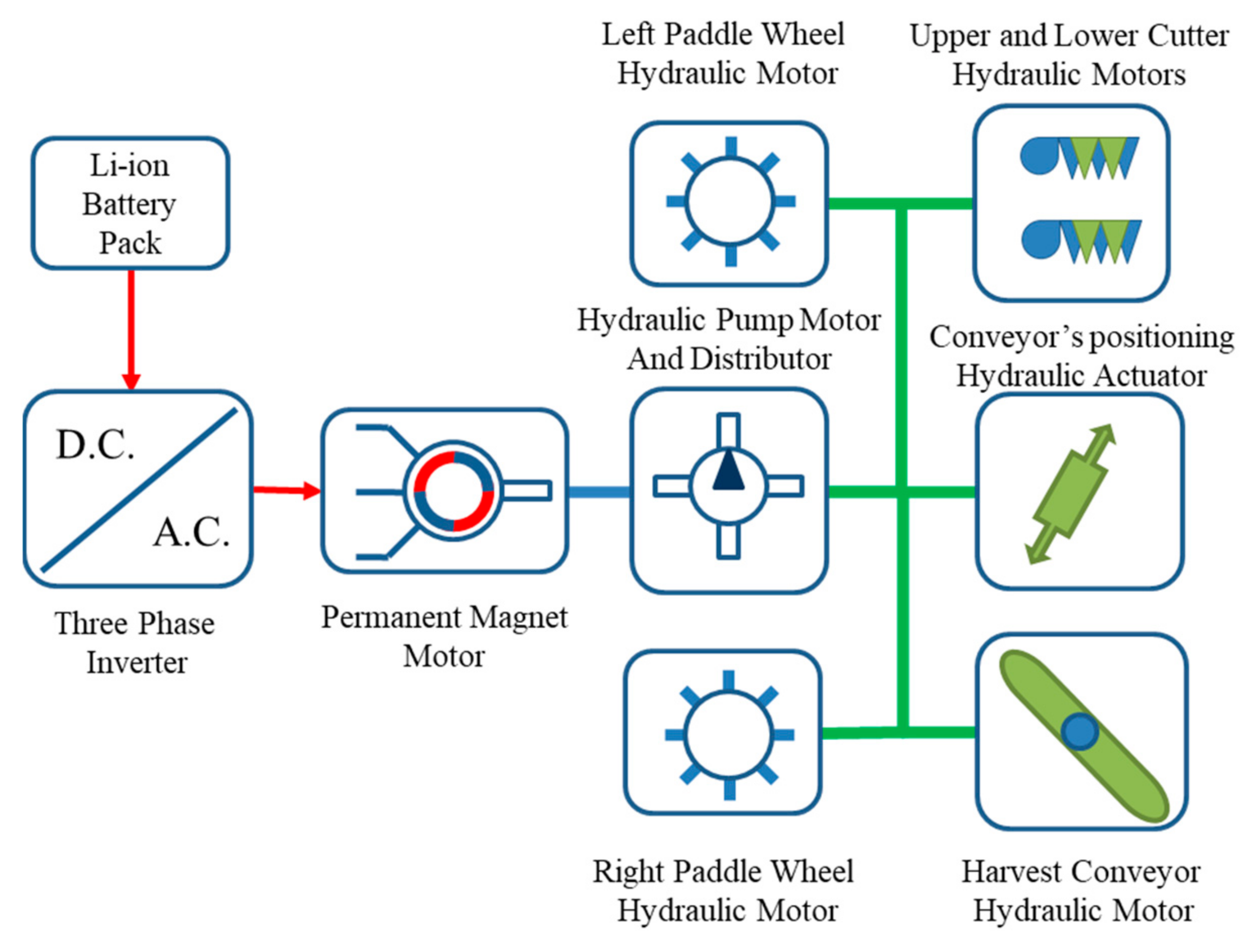
The diagram of the basic structure of the vehicle is presented in Figure 1.
A battery pack powers a three phase inverter which drives a permanent magnet motor that turns a hydraulic pump. The pump controls, through valves, all the functions of the harvester such as forward/backward motion, raising/lowering the cutter and the conveyor used to collect and deposit the harvested weed.
The main control block diagram is presented in Figure 2. Each component has its own individual control unit that consists of a board with a microcontroller. All the control units are connected on a common serial RS485 bus through which they receive commands from the Remote Controller unit, either by wireless link or by serial link, and send responses or execute the commands received, as well as monitor each equipment for operational conditions and fault occurrence. Previous work is referenced in [17].
The battery storage system also contains a battery monitoring system (BMS) which controls and monitors the parameters of the battery pack during charging operation or during normal functioning.
From a software point of view, the system is organized as a single master—multiple slave configuration, where the remote control unit has the role of master unit and the individual control units onboard the harvester are slave units. This aspect will be detailed in the Section 2.2 Software development.
The system can be used in two different topologies (see Figure 2):
- -
- remote controlled by using the radio communication between Remote Controller as master with Radio Unit as interface for RS485 bus connected to slave units CTRL#1-3;
- -
- direct controlled by the driver which is located on the vehicle and plugs in the Remote Controller unit directly to the RS485 bus on the vehicle, using optional RS485 link.
Those two operating modes are covering all the requests of the operators:
- -
- when harvesting, the driver is not exposed to dust, splashes and vibrations as it can control the harvester from the shore or from another boat;
- -
- when moving the boat and parking, the driver can fine-control the aquatic harvester.
Since most of the aquatic weed harvesters present on the market have a power rating between 16 kW and 80 kW [18,19,20,21], based on a tradeoff between power and size, a 30 kW peak power rating with an imposed autonomy of 1.5 h are guidelines for the proposed electric harvester. Considering the average energy consumption of some of these solutions as well as other machines developed by the authors, such as electric tractors [22] having similar power ratings and working conditions, we estimate an average power consumption of 18 kW. To achieve the required autonomy, the battery has to be sized according to the following formula:
where E is the energy requirement in kWh, Pcons is the average power consumption in kW and Taut is the working time (autonomy) in hours.
E > Pcons ∙ Taut = 18 kW ∙ 1.5 h = 27 kWh
Since Li-ion batteries cannot be fully discharged without damaging them, a safety discharge threshold of 20% is chosen, this gives us a margin of 80% discharge, taking this into account the final rating of the battery is the following:
Ebat > E/0.8 = 27 kWh/0.8 = 33 kWh
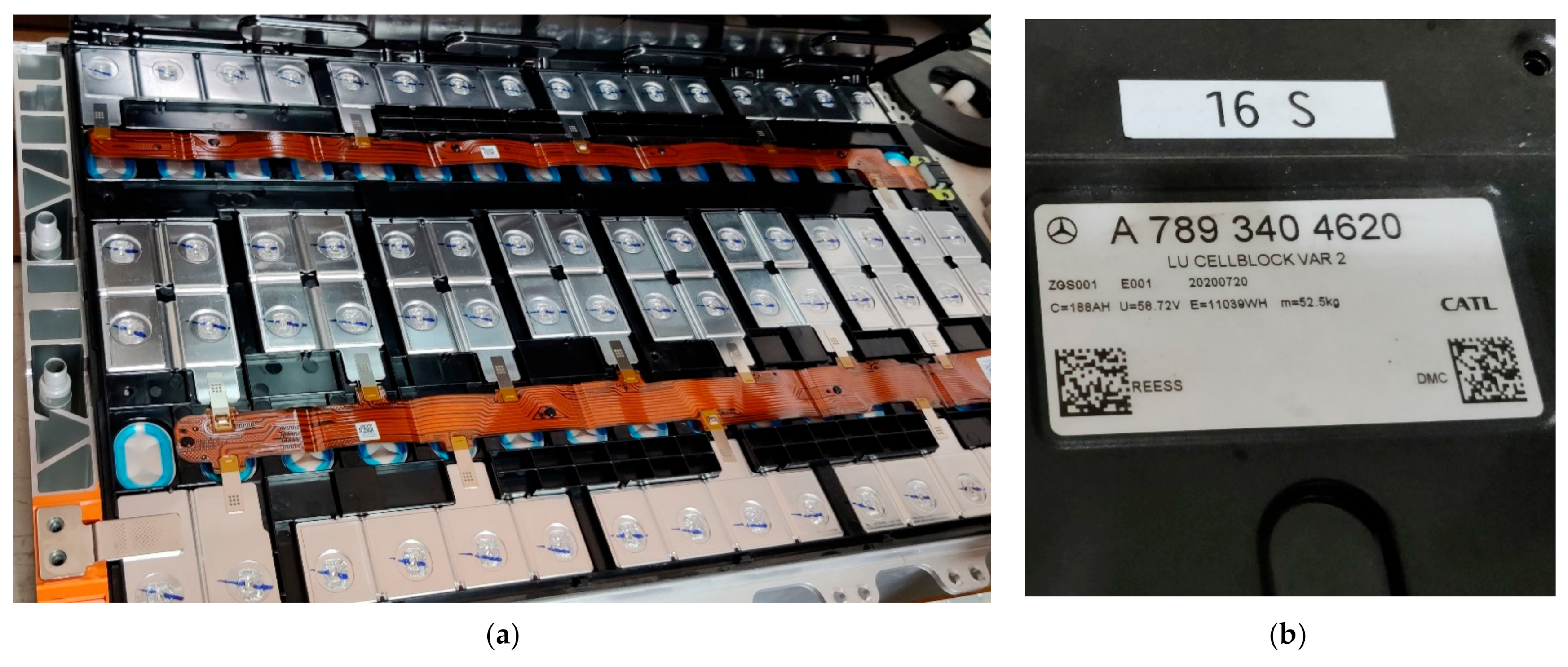
This capacity can be realized using 3 × 11 kWh type 16S CATL battery pack modules [23] in parallel, these modules are used in the electric vehicle industry. This battery pack, Figure 3, was chosen because it also follows REESS guidelines concerning protection against electrical shock, fire resistance, mechanical integrity, overcharge, overdischarge and over-temperature protections.
Two parameters of the battery pack are important for the sizing of the motor and power converter, the battery capacity, Cbat, and the rated voltage, Ubat. For the specified battery pack these parameters have the following values:
Cbat = 188 Ah
Ubat = 58.72 Vdc
For battery management an Orion BMS 2 [24] battery management system was chosen to manage and protect the battery packs. This BMS is suitable for use in electric, plug-in hybrid and hybrid electric vehicles as well as stationary applications. It can provide cell balancing for packs of 24 to72 cells, it also monitors the charging current and the total voltage of the battery pack and controls the charging and discharging functions for the battery.
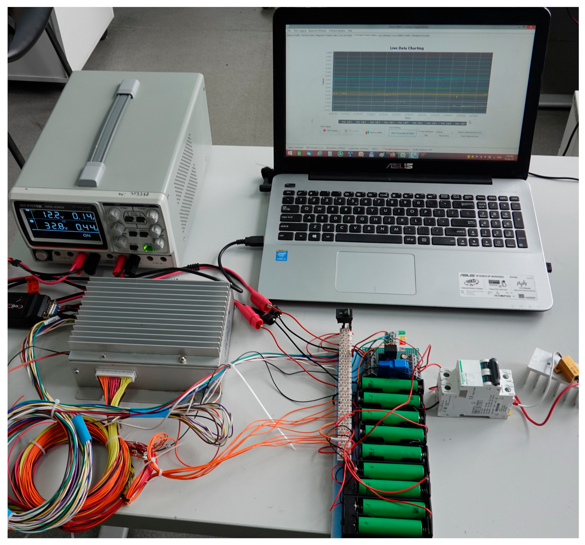
The BMS also is equipped with 2 CAN controllers allowing flexible integration in a vehicle CAN network. In this application one CAN interface is used to communicate with the battery charger to prescribe the charging voltage and charging current, while the second one is integrated in the harvester diagnostic data line, by the control unit #1, which converts the CAN data packets from the BMS to RS485 data packets. In Figure 4 we present an experimental setup for communication testing of the BMS while connected to a small battery pack.
For the three paralleled battery pack, each one is equipped with its own BMS, with high speed fuse and with DC contactor. Since each battery pack is managed by its own BMS, the charging signals, (BAT#_CE), from the three BMS where connected in series with the help of control relays so that a logical “AND” function would be realized, this means that charging will start only if all three packs need charging. This was a necessity because we are using a single charger for three batteries connected in parallel. The best solution would be to have an individual charger for each battery but budget constrains forbid us to apply such a solution, so this was a compromise between price and safety. In a similar way the discharge signal where connected so as to be able to stop discharging if one of the batteries functions outside the normal range of voltage and current. Also each battery has its own contactor (Q1, Q2, Q3) and fuse (F1, F2, F3) that it can use to quickly separate from the rest if there is a problem, as in Figure 5. This method of connecting the charging and discharging signals while also using contactors and fuses provides redundant safety for each battery pack.
The battery pack will be charged with a 6.6 kW, 80 A, TC charger [25]. The charger was setup to communicate via the CAN interface to be able to receive the charging voltage and charging current values.
For this charger the CAN message format is the following, Table 1:
ID: 0x1806E5F4—29 bit CAN id;

Table 1.
Battery charger CAN message format.
| Position | Data Name | Comments |
|---|---|---|
| Byte 1 | Max allowed charging voltage (High Byte) | Scaling: 0.1 V/byte, offset: 0 |
| Byte 2 | Max allowed charging voltage (Low Byte) | |
| Byte 3 | Max allowed charging current (High Byte) | Scaling: 0.1 A/byte, offset: 0 |
| Byte 4 | Max allowed charging current (Low Byte) | |
| Byte 5 | Charging control | 0: start/1: stop |
Knowing the battery voltage, a power converter can be selected. This converter will drive an AC motor, so a three phase inverter is chosen that has to able to able to power the motor at peak load, as such the current rating of the inverter has the following value:
Imax > Pcons/Ubat = 30 kW/58.72 V = 500 A
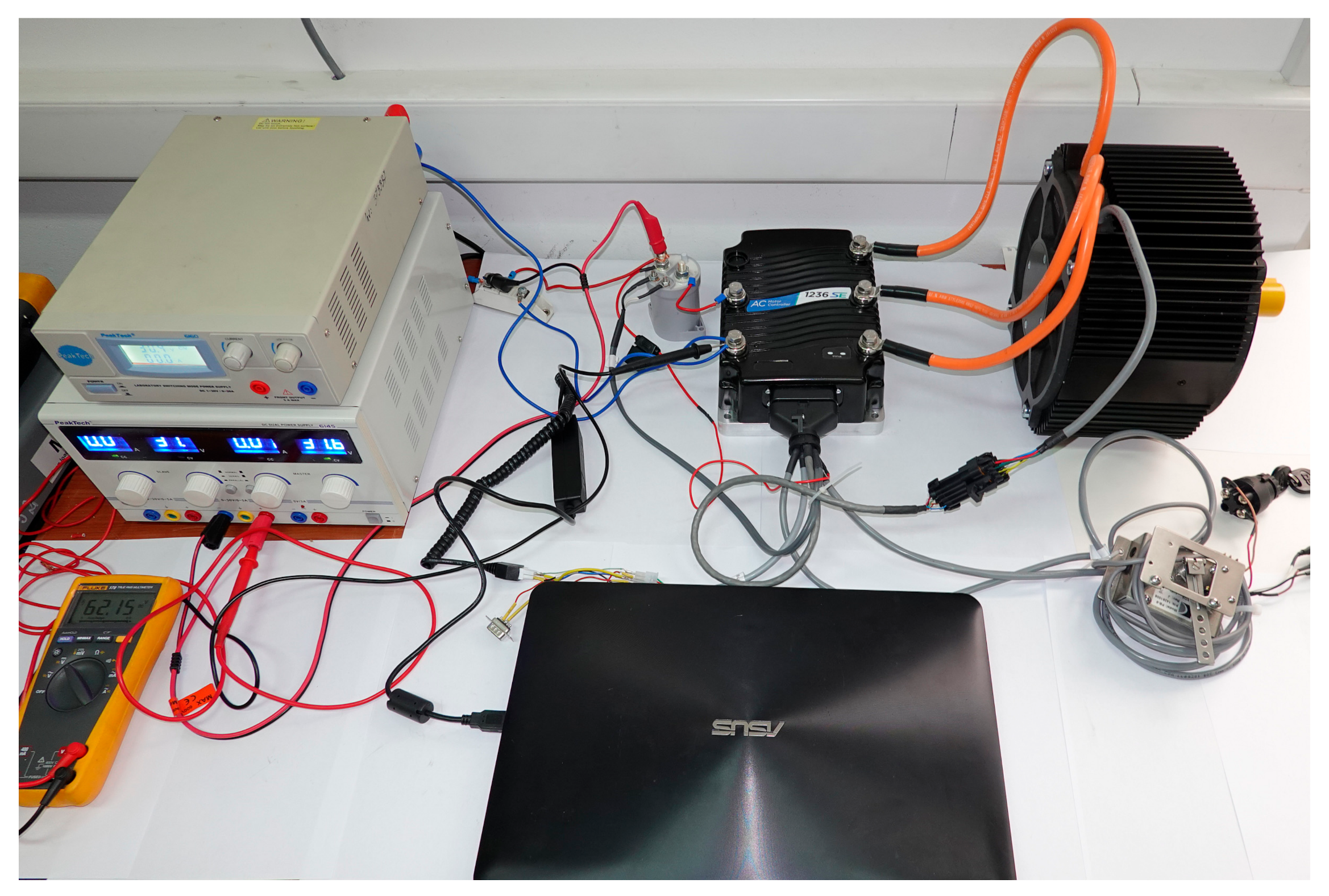
The three phase inverter 1236SE, Figure 6, from Curtis Instruments can drive Permanent Magnet (PMAC) motors, it operates with a maximum voltage of 80 V and a maximum current of 450 A. Another reason for this selection is the fact that the Curtis 1236SE has a special mode for pump motors [25], which we will use to drive all the hydraulic systems onboard.
Main characteristics of 1236SE-6401 controller are detailed in Table 2:
This type of inverter has been designed specifically to power electric vehicles, it has a high-performance processor control architecture to be able to conform to the modern requirements and standardization (electromagnetic compatibility according to EN 12895:2015, safety EN1175-1:1998 and IP65 rating according to IEC 60529), the control software allows for high energy efficiency of the drive system and it can operate with a wide range of input voltages.
The control software has the following characteristics:
- high frequency control pulses;
- automatically discharge of the DC link capacitors on shutdown;
- continuously tests all safety related parts of the control system;
- short circuit protection on all output drivers;
- thermal cutback, warning and automatic shutdown protection.
The final part is selecting a motor capable of producing the required power. The choice was made for a radial air gap, permanent magnet synchronous motor (PMSM) with an internal permanent magnet rotor (IPM) type ME1507. This motor is designed to work with sinusoidal (sine wave) controllers and has the specifications in Table 2:
2.2. Software Development
All the microcontroller units, both onboard the harvester and inside the remote control share a common software architecture based on a multitasking system [26,27,28,29,30]. The task scheduler is based on a time step, generated by an internal timer of the microcontroller, each task having allocated a specific amount of time to do its job.
A priority interrupt allows tasks that must be executed at precise intervals to be able to interrupt tasks that are not critical to the operation for the entire system. This method is less resource demanding when compared to a fully implemented preemptive tasking system. When using priority interrupt for the cooperative tasking, the context save is done automatically when the interrupt is activated thus avoiding the increased resource needs. Care must be taken however when assigning high priority to various tasks, the shortest task or fastest task can be high priority while slow task should be dispatched by the regular scheduler. In case the timing requirements are satisfied there is no need for priority assignment.
2.2.1. Communication Protocol and Real-Time Control
The communication protocol for all the units of the mobile harvester platform uses a time division algorithm with fixed slot allocation for every unit, each unit being assigned a unique identifier inside the network. The duration of a time slot (TS) is 60 ms.
During each time slot the remote control unit, which acts as communication master (master id = 0x24) for the network, sends a command frame to a specific control unit (CTRL#1 control unit #1 id = 0x28, CTRL#2 control unit #2 id = 0x2A, CTRL#3 control unit #3 id = 0x2C) onboard the harvester, as shown in Figure 2, each unit responding based on the operation code addressed to it. During communication all data frames are being checked using the checksum byte, thus ensuring error free communication.
The hardware layer for the protocol is realized by using the RS485 standard, onboard the harvester platform, while the remote control unit communicates with the platform using the wireless radio 2.4 GHz frequency band. An optional serial RS485 plug is available on the remote control unit that can be connected to the platform control system allowing wired communication.
The communication package has the following format:
SOF, DEST, OPCODE, EXT, SRC, DP0, DP1, DP2, CS
Where:
- SOF—is the start of frame byte;
- DEST—is the destination address byte of the control unit being interrogated;
- OPCODE—is the code byte for the desired operation;
- EXT—is the extended code byte;
- SRC—is the source address of the data frame that issued a command or response;
- DP0, DP1, DP2—are the data payload bytes;
- CS—is the checksum byte used for error detection.
- The checksum is calculated according to the following formula:
CS = (DEST + OPCODE + EXT + SRC + DP0 + DP1 + DP2) & 0xFF
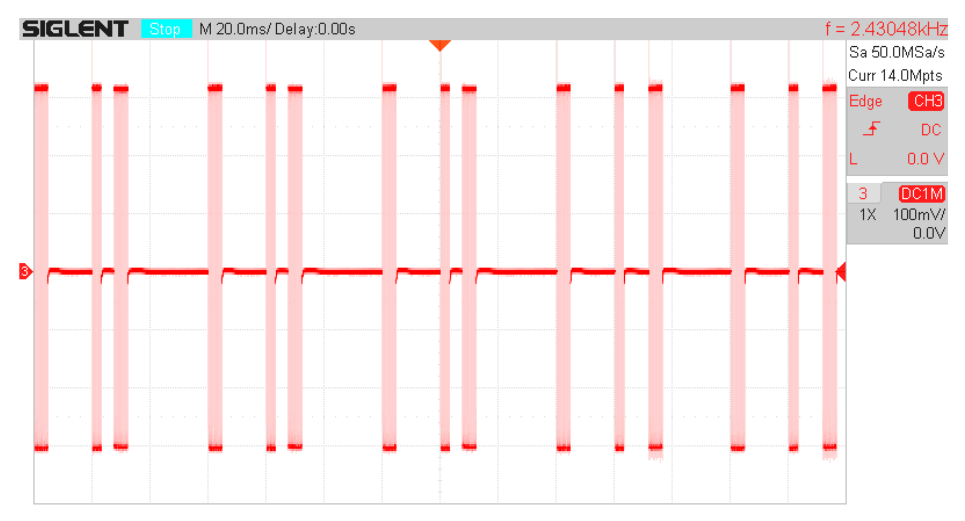
As can be seen in Figure 7, there are 5 time slots initiated with a long beacon message from master, followed at 20 ms by a short data request from master and a long answer from the designated slave unit.
In Table 3 we captured all the traffic for 16 time slots, in standby mode.
In Table 3 we can notice the beacon message, the data request and the answer. Every package has a control sum which is automatically checked for message validation. Missing several packages will generate the Idle status of the drive.
The beacon message presented in Table 3 is composed from Start of frame *, Character counter E, Destination 40, Opcode 50, Extension 00, Source 24, data D1 00 and D2 00, completed by Checksum B4. The D1 and D2 are used to send hydraulics commands within the beacon message and will be decoded and executed by the CRTL#3 control unit. The odd messages will contain the reference values for the right and for the left paddle wheels, and the even messages will contain the 2 Status bytes reflecting the status of the remote control buttons and the alarms presented in the whole system.
2.2.2. Diagnose Using the Built-in Battery Management System
The Battery’s Management System is consisting in three similar-built electronic units, each one being responsible for one battery, and all BMS connected to the same CAN communication bus, thus being connected to the CTRL UNIT #1. The BMS are not receiving any command, but they are reporting using CAN and CTRL UNIT#1 to the communication the values presented in Table 4.
The information provided by the BMS is to be used as presented in the discussion section. The aim of transmitting this info about the battery’ status is to perform signaling in case of malfunctioning and to disconnect the batteries using each individual DC contactor. The evolution of the relevant values is can be memorized and can be the base for further improvements on the operation of the battery, of the BMS and of the vehicle as-a-whole.
2.2.3. Motor Controller’s Parametrization
The controller of the electric motor is connected to the serial communication bus RS485 and the data exchanged (Table 5) with the driver’s remote control is:
- Prescribed Speed for the motor (in rpm, 2 byte) which is set according to the power needs of the system, with a lower speed for idle mode and a higher speed for full action (like harvesting with cutter on, conveyer on and paddles throttle on);
- Measured phase RMS current (in A, 2 bytes);
- Prescribed status for the motor’s controller (2 bytes);
- Measured DC supply voltage of the controller (in V, 1 bytes);
- Real speed of the motor (in rpm, 2 byte);
- CTRL #2 Status (1 byte);
The parameters of the controller (Table 6) and of the motor are implemented in the configuration state of the system, when the controller and the motor must be defined by programming them, using special tools for communication and a PC-resident software.
2.2.4. Software for the Electro-Hydraulic Controller
The electro-hydraulic controller receives commands via the RS485 bus, and activates several relays or transistors which are used to supply the dedicated electro-hydraulic valves in the hydraulic actuators. The command bytes presented in Table 7 of the Hydraulic controller CTRL#3 are included in the beacon signal, as there are commands that must be real-time effective and is very important to have a reduced transmission time for such commands.
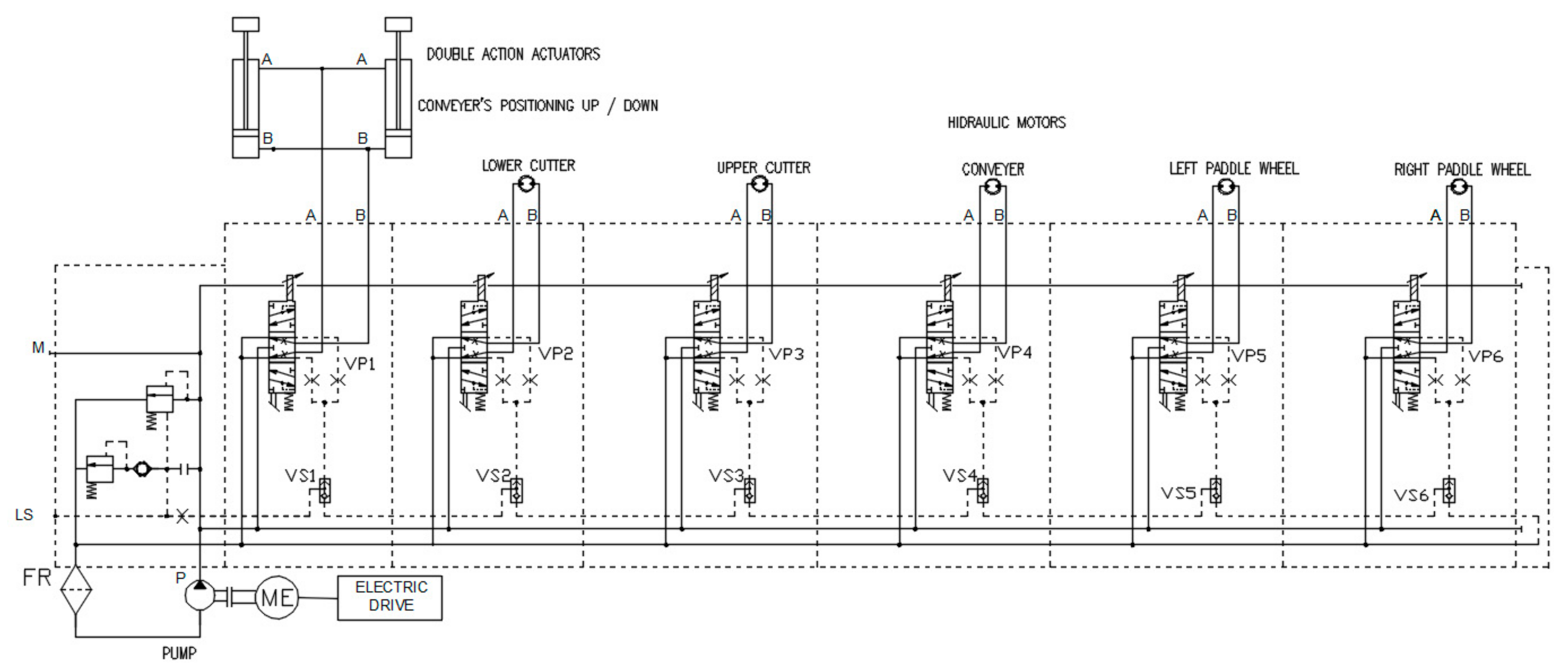
The moving commands from the 2 throttle joystick potentiometers will be transmitted by the remote control to the electro-hydraulic controller, which will compute 2 separated PWM signals for the 2 proportional valves and 2 solenoid valves, which are controlling the oil flow through the 2 hydraulic motors for the paddles, one PWM signal applied to the proportional valve VP5 activates the rotation of the paddle wheel located in the left side of the boat, considered when placed on the boat and facing the cutter side, as seen in Figure 8). Similarly, the second proportional valve VP6 is dedicated to the rotation of the paddle wheel located in the right side of the boat [31,32,33]. The direction of each paddle wheel is decided by the corresponding solenoid valves VS5 and VS6.
The hydraulic components used in the harvester are:
- -
- Pump P, is the hydraulic pump 250 bar, 1500 rpm, Maximum flow 140 L/min;
- -
- Solenoid valves VS1-6, one way valves;
- -
- Proportional valves VP1-6, are solenoid proportional flow control valve, poppet normally closed, pressure compensated;
- -
- two double action actuators for conveyor’s positioning actuators.
The hydraulic pump is driven by the electric motor with constant speed and the pressure in the hydraulic system is maintained at a constant value by using a spring valve. Each motor and actuator connected to the hydraulic distributors are supplied by using a proportional valve and a solenoid valve, thus being possible to supply each circuit with a specific and regulated pressure, value which can be adjusted during commissioning tests for a smooth, fast and secure operation of each of the individual mechanism.
For the cutter and the lattice conveyor belt, for byte-level commands are mirroring the position of the remote control selectors. These commands can be selected independently from the moving commands.
In order to perform a remote diagnostic of the system, the oil pressure information must be transmitted at the remote control unit and displayed on screen (if available).
The water level from 4 transducers are used to implementing two main functions:
- -
- their average value will measure the load of the vehicle;
- -
- the unbalanced values will characterize the swing and the capsize of the boat.
The water quality sensor is to be used, remotely, during harvesting.
3. Results
The driving system of the vehicle equipped with electro-hydraulic converter is characterized as robust and predictable. The worst characteristic of this driving system is the long response time. The delays between the commands and the actuator’s operation are caused by both the electric system’s response time and the hydraulics’ response time.
Our work was focused on obtaining a faster response time, using the best solution for both the electric and the hydraulics.
For electric commands we are using a multiple controller architecture, with one master and with several slaves. We have to have faster control loop on master controller and predictable communication messages chain for serial RS485 bus.
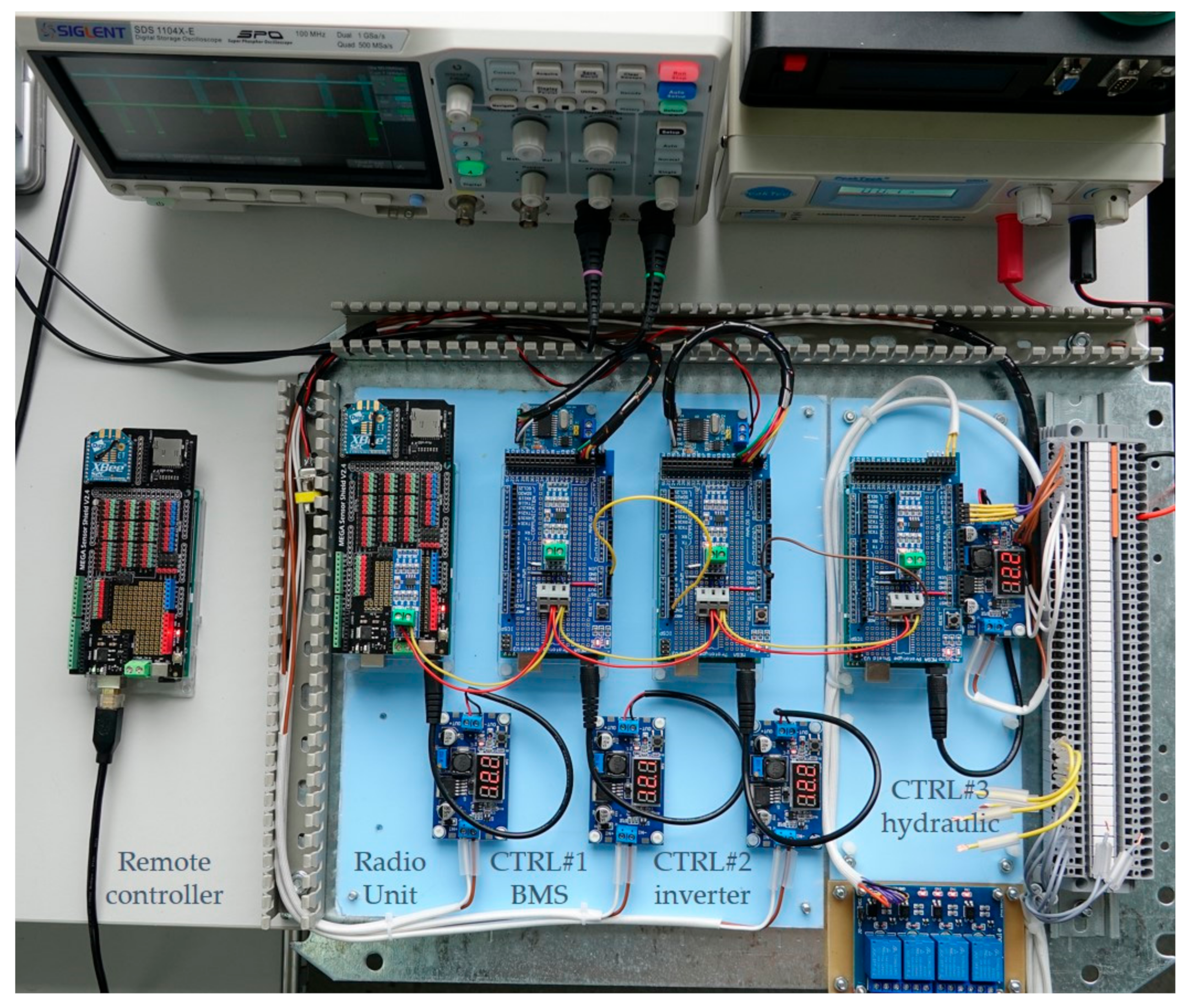
The electronic components were set-up and mounted inside a cubicle which protects against moisture and dust. The communication between the master and the three slaves was implemented and tested, as captured with an oscilloscope in Figure 7 and the hexadecimal data packages captured in Table 2. The performed measurements and validations are presented in this chapter. The experimental model is presented in Figure 9.
There are five microcontrollers ATmega 2560 with extension boards placed on top, being (from left to right) Remote Controller, Radio Unit, CTRL#1—BMS, CTRL#2 –inverter, CTRL#3—Hydraulic. Each extension board accommodates an RS485 converter. Four supply converters are used, and a relay output for the solenoid operation is placed on the panel, also. Remote controller and Radio unit have a 2.4 GH radio module. Near the CTRL#1 and CTRL#2 are placed two CAN converters for communicating with the BMS’s and with the inverter’s controller units.
3.1. Radio Communication and Command Processing
After we set-up the electronic components and we load the communication software in all four controllers, we develop a Remote Controller with radio communication. The messages from this controller are exchanged with the Radio Unit, and all the received messages are transmitted directly on the RS485 control bus. Additionally, the messages received on the same bus by the Radio Unit controller are broadcasted immediately to the Remote Controller by radio signal. While there is a master-slave architecture of the controllers, there will be no conflicts between all those messages, as the slave controllers will broadcast messages only by requests of the master controller, while the master controller maintain a time slot long enough that any slave controller can deliver his answer.
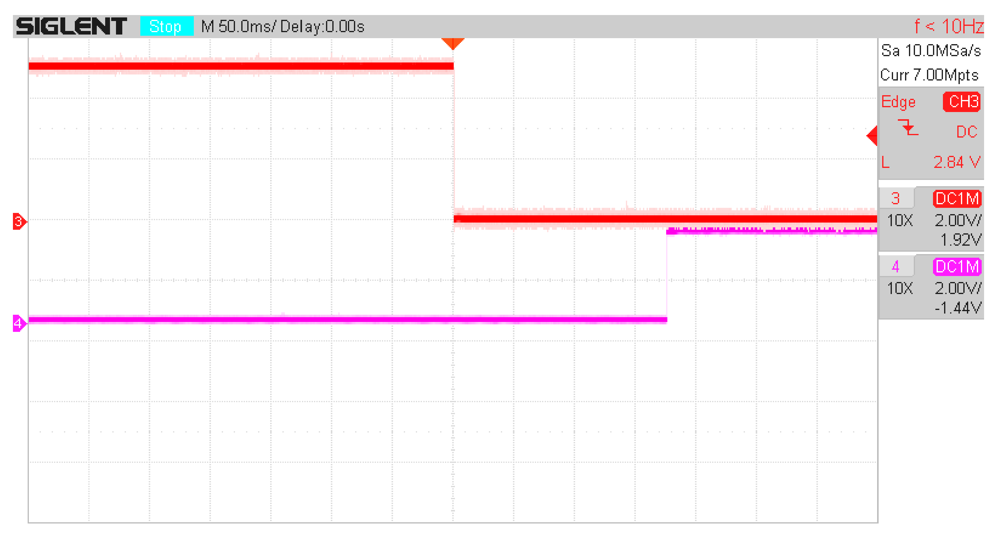
After we set up the timers of the communication, we perform test regarding the delay generated from the time of the I/O input (pushed button) on the Remote Controller till the time the relay output of the CTRL#3 activates (hydraulics controller). An example of this delay was captured by oscilloscope and presented in Figure 10.
The delay is 178 ms, and is the longest we have captured. The analyze of this delay show us that there are some timers involved, such as:
- Tlp, time of the software loop inside the controller, set at 10 ms;
- Tin, time to read the Input, consists in 3–3.99 × Tlp as the input is validated in three consecutive loops;
- Tbcn, time for a beacon message to be broadcasted, app 5 ms;
- Tcmd, time for a command message to be broadcasted, app 3 ms;
- Trct, time for a slave to react to command, max 10 ms;
- Tans, time for an answer message to be broadcasted, app 5 ms;
- Tts, time slot for the beacon message, set at 60 ms;
- Tfc, time for a full command message, set at 120 ms;
The time slot for the beacon is set at 60 ms, time enough that a beacon and a command can be emitted by the master, the command is received by the slave, processed and the answer is broadcasted on the same time slot.
As we can see in Figure 7, all the activity within a time slot is completed in less than 45 ms, but that is the situation with the best operation, with low length connections. This communication system we are using is dedicated to operate in the worst conditions, including electromagnetic noise, distributed systems with long cables and different controllers with different reaction times and different loop timers.
Moreover, if we are analyzing the delay regarding the hydraulic controller, which is the most important delay considering the impact on the maneuverability of the harvester, a complete command is performed at each 2 beacon messages, (see Section 2.2.1). Thus, the maximum delay Tmd can be computed as:
The shortest time is:
The real time is between 95 and 120 ms, depending how the command is related to the asynchronous communication based on beacon. The communication delay is small and will not be noticed by the operator.
3.2. Real-Time Operation
The following timings and delays were measured on the electric system:
- -
- Remote controller to Radio unit controller, via Radio comm.: <10 ms;
- -
- Radio controller to controllers CTRL UNIT #1-3, via RS485 bus: <60 ms;
- -
- Report from CTRL UNIT #1–3 to radio controller, via RS485 bus: 10–480 ms;
- -
- CTRL UNIT #3 to hydraulic system using relay output: 4–30 ms.
For the communication between the BMS and the controllers, which is more a diagnose-oriented communication, as no commands will be sent to the BMS. The overall response time of 0.5 s is fair, while the transmission delay of the message is less than 20 ms.
The communication between the Motor’s Inverter and the remote is has a maximum 0.5 s transmission time, while the transmission delay is 20 ms. The motor must be driven linearly, as it will operate mainly in steady speed mode. For a faster response time, like in case of hydraulic puncture, a direct link is implemented between the CTRL UNIT #3 and CTRL UNIT #2 to obtain an instant stop of the electric motor in case of a hydraulic failure.
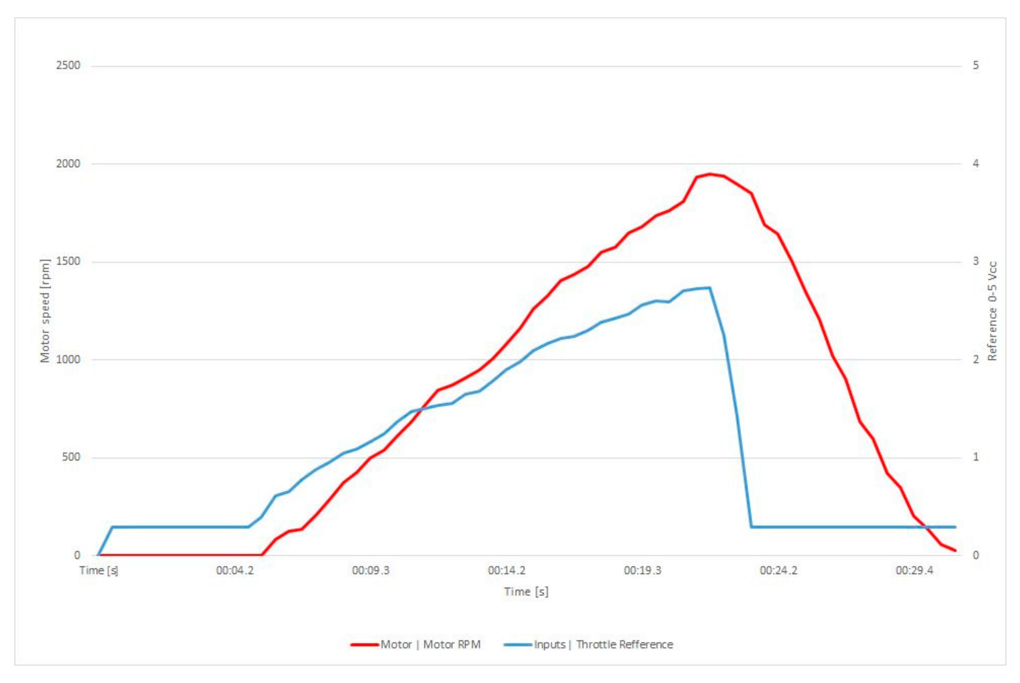
The response time of the speed of the motor is presented in Figure 11.
The delay between the reference trip and the motor’s trip can be observed, in Figure 11, at the moment 21.7 s, when the speed reference is decreasing from 2.7 V down to 0.29 V (stop) and the speed is following the stop command after 0.5 s, with a slope of 200 rpm/s.
For the communication between the remote and the CTRL UNIT#3, the command from the joystick vipers and from the switches of the remote controller are transmitted on the serial RS485 bus packed inside the beacon type message, as presented before. Practically, at every 120 ms there is a new command for the hydraulics. We have the maximum 60 ms transmission time, two time slots, and the transmission delay is 20 ms.
For this controller, the operation of the valves is done in two different ways:
- -
- for the solenoid valves, the commands are transmitted by using relays, which are closed with 6–8 ms delays, and the solenoid valve is operating in 15 ms [28];
- -
- for the proportional valves, the electric commands are PWM signals commanded using a transistor board interface. The pulse width of the signal is correlated with the remote control joystick positions, but the width is regulated from o to maximum position.
In order to obtain a linear progression of the output pressure applied to the hydraulic motor, the variation of this PWM signal is smoothed by imposing a rising slope of 2 s for the PWM from 0 to maximum value. The 2.5 s refers to a delay we imposed in the control system of the hydraulic motors for the paddle wheels that move the vehicle. This delay represents a ramp up time from the moment a pressure command is received until the system achieves that pressure. This is a safety measure to avoid stress in the hydraulic system [33].
3.3. Limits and Protections
For the complex electro-hydraulic system, we must set some limits and we must activate some protections. Some of them are provided using hydraulic equipment, but most of them are electric and electronic protections. The values presented in Table 8 are prescribed values to be set in the non-volatile memory of the electronic controllers, during commissioning.
4. Discussion
Improving the vehicle’s maneuverability by improving the driver’s assistance is performed by right-left independent paddle wheels, by constant pressure hydraulic pump and by remote or on-board control panel.
The main issue of our work is to prepare an aquatic harvester powered from electric battery storage, and to operate more than a 90 min per charge, with remote control. The recommended solution for such harvester is based on the hydraulic propulsion (already validated), and to drive the hydraulic pump by an electric motor.
On the other hand, to supply an electric motor from a battery comprises that you have, at least, a battery management system and a motor controller (power inverter).
Also, for remote control of such vehicle, a radio operated remote control must be used, mostly because of the medium range implied.
One of the most important feature of this remote controlled vehicle is the ability to easily connect to a GSM modem which can be used to send data over GSM network to a static or to a cloud storage system for remote diagnose and future analysis.
Starting with this requests, our team developed an electric powered traction system with 3 paralleled storage batteries with nominal voltage of 58,4 V, and total capacity of 33 kWh, a permanent magnet synchronous motor operated at constant speed for 18 kW output, connected to a hydraulic pump, and individual valves for different hydraulic motors for the harvesting operation and for the throttle of the vehicle using paddle wheels.
In this paper we are presenting the individual components of the vehicle, insisting mainly on the control diagram based on microcontrollers, specially designed for this application, using “master and multi-slave” architecture with proprietary asynchronous serial communication bus. The communication uses beacon-type data transmission from the master with 60 ms time slot, and each slave can report to master at his allocated time-slot. As commands are included inside two consecutive beacon messages, the operating control time slot is 120 ms, a fast enough control loop for the electrohydraulic converter.
The complete beacon cycle has 480 ms, and is more than satisfactory for diagnose use of data. Data provided for diagnose completes 12 bytes of data, as described.
The maneuverability of the boat is increased by smoothing the traction commands when using rise and fall limiters for the start and for the stop of the vehicle, thus being possible by using electronic controllers.
Keeping manual override for automated control is enabled, so the driver can perform special maneuvers to steer and tilting of the vehicle, when needed.
Also, for the protection of the equipment and for the operation in case of a failure, several protections are provided, mostly for the electronic parts and for the electric motor. A pressure loss is also supervised, and a direct I/O link between slave controllers is ensured for the mitigation of the effects of a hydraulic failure.
From the driver’s side, several requests have been received stating that during parking to the shore and during the trip to the harvesting point, there is need for an on-board driver. The fastest way is to wire-connect the remote control diagnose directly to a connector on the boat, and to use it as a built-in control interface. The solution from Figure 2 complies with all those requirements and can control several controllers at once.
5. Conclusions
Transmission time and delays have been measured and the solutions to improve the behavior on real-time of the system were implemented and tested as presented in Section 3. A 0.5 s overall delay in operation is fast enough, with less than 120 ms for the command-to-execution time due to the electronic control.
Laboratory tests were completed and the equipment can, now, be mounted in s special aquatic vehicle, prepared for e-powering, while solving a problem of a dedicated vehicle able to comply with the requests from the open water operators in order to clean the aquatic weed in an ecological way so the birds and the fish are not frightened in their natural environment.
The same operating principle (of multiple controller network) can be used is several vehicles which are supposed to have fast driving capabilities and versatility.
Also the diagnose features is very important, especially for newly vehicles with special control strategies and different type of equipment.
Author Contributions
Conceptualization, E.T., I.V. and M.-G.M.; methodology, E.T., M.-G.M. and I.-C.S.; software, I.V.; validation, E.T., M.-G.M. and I.-C.S.; formal analysis, E.T., M.-G.M. and V.S.; investigation, I.V. and I.-C.S.; resources, E.T. and I.V.; data curation, E.T. and M.-G.M.; writing—original draft preparation, I.V.; writing—review and editing, E.T., M.-G.M. and V.S.; supervision, E.T. and M.-G.M.; project administration, M.-G.M. and V.S.; funding acquisition, E.T., M.-G.M. and V.S. All authors have read and agreed to the published version of the manuscript.
Funding
This work was supported by a grant of the Romanian Research, Innovation and Digitalization Ministry, through Sectorial Plan, contract no. 1PS/2021 and partially from projects 46N/2019 and 25PFE/2021.
Institutional Review Board Statement
Not applicable.
Informed Consent Statement
Not applicable.
Data Availability Statement
Not applicable.
Conflicts of Interest
The authors declare no conflict of interest.
References
- Haller, W.T. Mechanical Control of Aquatic Weeds, University of Florida, Gainesville, USA. Available online: http://aquatics.org/bmpchapters/3.5%20Mechanical%20Control%20of%20Aquatic%20Weeds.pdf (accessed on 1 March 2022).
- Gorham, P. Aquatic Weed Management in Waterways and Dams, Noxious Plants Advisory Officer, NSW DPI, Richmond, USA. Available online: https://www.dpi.nsw.gov.au/__data/assets/pdf_file/0020/256403/Aquatic-weed-management-in-waterways-and-dams.pdf (accessed on 1 March 2022).
- Sperry, B.P.; Haller, W.T.; Ferrell, J.A. Mechanical Harvesting of Aquatic Plants. Available online: https://corpslakes.erdc.dren.mil/employees/invasive/pdfs/MechanicalHarvesting.pdf (accessed on 1 March 2022).
- Adam, J. Catalytic Conversion of Biomass to Produce Higher Quality Liquid Bio-Fuels. Ph.D. Thesis, NTNU, Trondheim, Norway, 2005. [Google Scholar]
- Argun, H.; Kargi, F. Bio-hydrogen production by different operational modes of dark and photo-fermentation: An overview. Int. J. Hydrogen Energy 2011, 36, 7443–7459. [Google Scholar] [CrossRef]
- Badger, P.C. Ethanol from cellulose: A general review, Trends in new crops and new uses. In Proceedings of the Fifth National Symposium, Atlanta, GA, USA, 10–13 November 2001; pp. 17–21. [Google Scholar]
- Demirbaş, A. Bioethanol from Cellulosic Materials: A Renewable Motor Fuel from Biomass. Energy Sources 2005, 27, 327–337. [Google Scholar] [CrossRef]
- Bartrons, M.; Gratton, C.; Spiesman, B.J.; Vander Zanden, M.J. Taking the trophic bypass: Aquatic-terrestrial linkage reduces methylmercury in a terrestrial food web. Ecol. Appl. 2015, 25, 151–159. [Google Scholar] [CrossRef] [PubMed] [Green Version]
- Mireia, B.; Sardans, J.; Hoekman, D.; Peñuelas, J. Trophic transfer from aquatic to terrestrial ecosystems: A test of the biogeochemical niche hypothesis. Ecosphere 2018, 9, e02338. [Google Scholar] [CrossRef] [Green Version]
- Cakır, A.; Ozmihci, S.; Kargi, F. Comparison of bio-hydrogen production from hydrolyzed wheat starch by mesophilic and thermophilic dark fermentation. Int. J. Hydrogen Energy 2010, 35, 13214–13218. [Google Scholar] [CrossRef]
- Da Silva, V.T.; Mozer, T.S.; da Costa, D.; da Silva César, A. Hydrogen: Trends, production and characterization of the main process worldwide. Int. J. Hydrogen Energy 2017, 42, 2018–2033. [Google Scholar] [CrossRef]
- Omofunmi, O.E.; Ebifemi, S.A.; Eweina, A.B. Design of Water Hyacinth (Eichhornia crassipes) Harvester. J. Sci. Res. Rep. 2016, 10, 1–10. [Google Scholar] [CrossRef]
- Matur, M.; Bhavi, I.; Lingappa, S. Development of Low Cost Miniature Weed Harvester to Control Water Hyacinth. Nat. Volatiles Essent. Oils 2021, 8, 1203–1212. [Google Scholar]
- Salunke, S.; Katikar, N. Unifying Knowledge Management Parameters with Mechanical Tools Building Empirical Control Strategy towards Sustainable Development. Int. J. Appl. Environ. Sci. 2017, 12, 1313–1335. [Google Scholar]
- Kumar, G.D.; Sreecharan, B.A.; Kiran, T.S.; Sai Sandeep, S.S.; Mouli, S. Design and Fabrication of an Automatic Water Hyacinth Removal and Prevention Machine. Int. J. Innov. Technol. Explor. Eng. 2020, 9, 450–454. [Google Scholar] [CrossRef]
- Hunan Zhongke Water Environment Treatment Co., Ltd. Small Electric Remote Control Aquatic Weed Harvester. Patent CN101990811A, 26 October 2009. Available online: https://patents.google.com/patent/CN101990811A/en (accessed on 1 March 2022).
- Rădulescu, V.; Străinescu, I.; Tudor, E.; Bozaș, F.; Dascălu, A.; Brăslașu, D. The integration of the traction equipment into the vehicle computer network. WIT Trans. Built Environ. 2015, 146, 392–397. [Google Scholar] [CrossRef] [Green Version]
- Remote Controlled 3-in-1 Cutter, Skimmer, and Collector. Available online: https://lakeweedharvester.com/watergator/ (accessed on 1 March 2022).
- Eco-Cutter|Aquatic Weed Harvester. Available online: https://weedersdigest.com/eco-cutter-aquatic-weed-harvester/ (accessed on 1 March 2022).
- Aquatic Weed Harvester. Available online: https://mavideniz.com.tr/our-production/vessels-boats/aquatic-harvester-barge/aquatic-weed-harvester/ (accessed on 1 March 2022).
- Water Weed Harvester. Available online: https://content.isuzu.com.au/power-solutions/ips-water-weed/ (accessed on 1 March 2022).
- Tudor, E.; Matache, M.G.; Sburlan, I.C.; Vasile, I.; Cristea, M. Electric Circuits Dimensioning for Small Power Electric Tractor. In Proceedings of the ISB—INMA THE—International Symposium. Technologies and Technical Systems in Agriculture, Food Industry and Environment, Bucharest, Romania, 30 October 2020. [Google Scholar]
- Battery Management System Orion BMS2. Available online: https://www.orionbms.com/ (accessed on 14 April 2022).
- Electric Vehicle Battery. Available online: https://www.catl.com/en/solution/passengerEV (accessed on 14 April 2022).
- Curtis Motor Controller. Available online: https://cdn.curtisinstruments.com/products/datasheets/SESeries_datasheet_en.pdf (accessed on 14 April 2022).
- Zhao, W.; Ramamritham, K.; Stankovic, J.A. Scheduling Tasks with Resource Requirements in Hard Real-Time Systems. IEEE Trans. Softw. Eng. 1987, SE-13, 564–577. [Google Scholar] [CrossRef]
- Zhao, W.; Ramamritham, K.; Stankovic, J.A. Preemptive Scheduling Under Time and Resource Constraints. IEEE Trans. Comput. 1987, 100, 949–960. [Google Scholar] [CrossRef]
- Kopják, J.; Kovács, J. Timed cooperative multitask for tiny real-time embedded systems. In Proceedings of the 2012 IEEE 10th International Symposium on Applied Machine Intelligence and Informatics (SAMI), Herl’any, Slovakia, 26–28 January 2012; pp. 377–382. [Google Scholar] [CrossRef]
- Lubbers, E.; Platzner, M. Cooperative multithreading in dynamically reconfigurable systems. In Proceedings of the 2009 International Conference on Field Programmable Logic and Applications, Prague, Czech Republic, 31 August–2 September 2009; pp. 551–554. [Google Scholar] [CrossRef] [Green Version]
- Rodriguez, N.; Silvana, R. Integrating Remote Invocations with Asynchronism and Cooperative Multitasking. Parallel Process. Lett. 2008, 18, 71–85. [Google Scholar] [CrossRef] [Green Version]
- Zhang, X.; Lu, Y.; Li, Y.; Zhang, C.; Wang, R. Numerical calculation and experimental study on response characteristics of pneumatic solenoid valves. Meas. Control. 2019, 52, 1382–1393. [Google Scholar] [CrossRef]
- Zhu, C.; Zhang, H.; Wang, W.; Li, K.; Zhou, Z.; He, H. Compound Control on Constant Synchronous Output of Double Pump-Double Valve-Controlled Motor System. Processes 2022, 10, 528. [Google Scholar] [CrossRef]
- Tran, N.H.; Le, C.; Ngo, A.D. Experimental investigation of speed control of hydraulic motor using proportional valve. In Proceedings of the 2017 International Conference on System Science and Engineering (ICSSE), Ho Chi Minh City, Vietnam, 21–23 July 2017; pp. 330–335. [Google Scholar] [CrossRef]
Figure 1.
Basic structure of the aquatic harvester.

Figure 2.
Block diagram of the control system of the aquatic harvester.

Figure 3.
(a) CATL 16S, 11 kWh battery pack; (b) REESS marking code.

Figure 4.
Experiment with Orion BMS2 battery management system and a small battery pack.

Figure 5.
Battery packs and charger with charge enable signal (CE) control.

Figure 6.
Curtis 1236SE three phase inverter connected to electric motor for preliminary test.

Figure 7.
Time slot mechanism used for serial RS485 communication.

Figure 8.
Hydraulic system diagram.

Figure 9.
Experimental model of the control electronics for an aquatic harvester electric vehicle.

Figure 10.
Example of transmission delay from Master IO input (red) to CTRL#4 output (magenta).

Figure 11.
Speed response of the electric motor—the reference and motor’s speed versus time.

Table 2.
Main characteristics of the electrical power components of the harvester.
| Unit | Characteristic | Value |
|---|---|---|
| Controller 1236SE-6401 | Rated voltage | 48–80 Vdc |
| Max current (2 min) | 450 Arms | |
| Max current (60 min) | 185 Arms | |
| Weight | 4.12 kg | |
| Electrical insulation | 500 Vac | |
| Dimensions | 165 × 232 × 85 mm | |
| Motor ME1507 | Peak power | 44 kW |
| Maximum speed | 6000 rpm | |
| Rated voltage | 48–120 Vdc | |
| Rated current | 250 Aac continuous | |
| Weight | 20 kg | |
| Battery 16S CATL | Charge voltage cut-off | 4.2 V/Cell, 67.2 V/Module |
| Discharging cut-off | 2.8 V/Cell, 44.8 V/Module | |
| Imax discharge (10 s) | 500 Amps | |
| Dimensions | 643 × 412 × 114 mm | |
| Weight | 52.2 kg |
Table 3.
Captured RS485 traffic for standby mode and 16 communication time slots.
| Beacon M | Data Request M-S | Answer S-M |
|---|---|---|
| *E40500024000000B4 | *828C9002415 | *E24DF00280000002B |
| *E4050002410000C4 | *828C9012416 | *E24DF01280000002C |
| *E40500024200000D4 | *828C9022417 | *E24DF02280000002D |
| *E40500024300000E4 | *82AC9002417 | *E24DF002A0000002D |
| *E40500024400000F4 | *82AC9012418 | *E24DF012A0000002E |
| *E4050002450000004 | *82AC9022419 | *E24DF022A0000002F |
| *E4050002460000014 | *82CC9002419 | *E24DF002C0000002E |
| *E4050002470000024 | *82CC901241A | *E24DF012C0000002F |
| *E4050002480000034 | *828C9002415 | *E24DF00280000002B |
| *E4050002490000044 | *828C9012416 | *E24DF01280000002C |
| *E40500024A0000054 | *828C9022417 | *E24DF02280000002D |
| *E40500024B0000064 | *82AC9002417 | *E24DF002A0000002D |
| *E40500024C0000074 | *82AC9012418 | *E24DF012A0000002E |
| *E40500024D0000084 | *82AC9022419 | *E24DF022A0000002F |
| *E40500024E0000094 | *82CC9002419 | *E24DF002C0000002E |
| *E40500024F00000A4 | *82CC901241A | *E24DF012C0000002F |
* is described as start of frame, a character the indicates start of data packet.
Table 4.
Battery Management System’s feedback signals, command 0xC9 from 0x24 to 0x28.
| OPCODE Byte | EXT Byte | Detail | Function |
|---|---|---|---|
| 0xC9 | 0x00 | Signed | Pack current High |
| Signed | Pack current Low | ||
| Unsigned | Pack SOC | ||
| 0xC9 | 0x01 | Unsigned | Pack voltage High |
| Unsigned | Pack voltage Low | ||
| Unsigned | Pack temperature | ||
| 0xC9 | 0x02 | Unsigned | Status BMS |
| Unsigned | Status Charger | ||
| Unsigned | Status CTRL#1 |
Table 5.
Electric drive feedback signals for command 0xC9 from 0x24 to 0x2A.
| OPCODE Byte | EXT byte | Detail | Return Data |
|---|---|---|---|
| 0xC9 | 0x00 | Signed | Motor current High [A] |
| Signed | Motor current Low [A] | ||
| Unsigned | Status | ||
| 0xC9 | 0x01 | Unsigned | DC supply voltage High [V] |
| Unsigned | DC supply voltage Low [V] | ||
| Unsigned | Status | ||
| 0xC9 | 0x02 | Unsigned | Motor’s speed High [rpm] |
| Unsigned | Motor’s speed Low [rpm] | ||
| Unsigned | Status CTRL#2 |
Table 6.
Main parameters of the controller.
| Parameter | Value | Description |
|---|---|---|
| Supply voltage maximum | 72 | Overvoltage threshold |
| Supply voltage minimum | 48 | Undervoltage threshold |
| Load current maximum | 450Arms | Overcurrent threshold |
| Control mode select | Speed Mode Express | Simple speed control |
| Max speed | 2500 rpm | Pump max speed |
| Acceleration rate | 5 s | From 0 to nmax |
| CAN baud rate | 1 = 250 kbps | Heartbeat rate 100ms |
| Temperature sensor (motor) | 3 = KTY84-130 | Linear sensor in stator coil |
| PWM Frequency | 10 | kHz |
Table 7.
Electro-hydraulic commands and feedback signals- command 0xC9 from 0x24 to 0x2C.
| OPCODE Byte | EXT Byte | Detail | Function |
|---|---|---|---|
| 0xC9 | 0x00 | Signed | Throttle 1—right paddle wheel |
| Signed | Throttle 2—left paddle wheel | ||
| Bit 0 | Cutter Up | ||
| Bit 1 | Cutter Down | ||
| Bit 2 | Cutter On | ||
| Bit 3 | Lattice conveyor On | ||
| Bit 4-7 | Unbalance level | ||
| 0xC9 | 0x01 | Unsigned | Oil Pressure sensor |
| Unsigned | Average level transducer with float | ||
| Unsigned | Water quality sensor |
Table 8.
Protections and limits used for electronic controller configuration.
| Protection Type | Description | Value |
|---|---|---|
| Hydraulic protections | by-pass valve from main pump | set value: 200 bar |
| overpressure valve | ||
| Electronic protections | maximum motor temperature | 125 °C |
| maximum motor speed | 2500 rpm | |
| short circuit current | 480 Aac | |
| maximum battery voltage | 72 Vdc | |
| Electronic limits | motor temperature for power limiter | 100 °C |
| power limiting map—nominal speed | 2500 rpm | |
| field weakening rate | 50% | |
| battery current limiter | 500 Adc | |
| regen battery current limit | 0 Adc (no regeneration) |
Publisher’s Note: MDPI stays neutral with regard to jurisdictional claims in published maps and institutional affiliations. |
© 2022 by the authors. Licensee MDPI, Basel, Switzerland. This article is an open access article distributed under the terms and conditions of the Creative Commons Attribution (CC BY) license (https://creativecommons.org/licenses/by/4.0/).
Share and Cite
MDPI and ACS Style
Tudor, E.; Matache, M.-G.; Vasile, I.; Sburlan, I.-C.; Stefan, V. Automation and Remote Control of an Aquatic Harvester Electric Vehicle. Sustainability 2022, 14, 6360. https://0-doi-org.brum.beds.ac.uk/10.3390/su14106360
AMA Style
Tudor E, Matache M-G, Vasile I, Sburlan I-C, Stefan V. Automation and Remote Control of an Aquatic Harvester Electric Vehicle. Sustainability. 2022; 14(10):6360. https://0-doi-org.brum.beds.ac.uk/10.3390/su14106360
Chicago/Turabian StyleTudor, Emil, Mihai-Gabriel Matache, Ionuț Vasile, Ion-Cătălin Sburlan, and Vasilica Stefan. 2022. "Automation and Remote Control of an Aquatic Harvester Electric Vehicle" Sustainability 14, no. 10: 6360. https://0-doi-org.brum.beds.ac.uk/10.3390/su14106360
Note that from the first issue of 2016, this journal uses article numbers instead of page numbers. See further details here.