
Effects of the Concrete Strength and FRP Reinforcement Type on the Non-Linear Behavior of Concrete Deep Beams

 , , ,
, , , 
Abstract
:1. Introduction
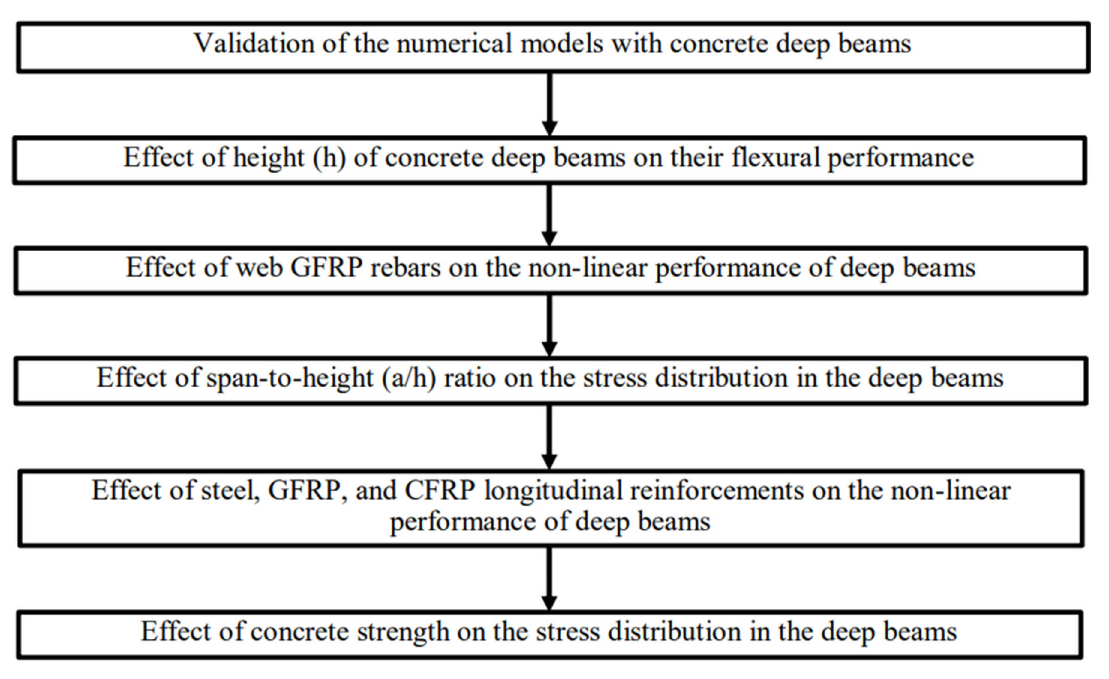
2. Methodology
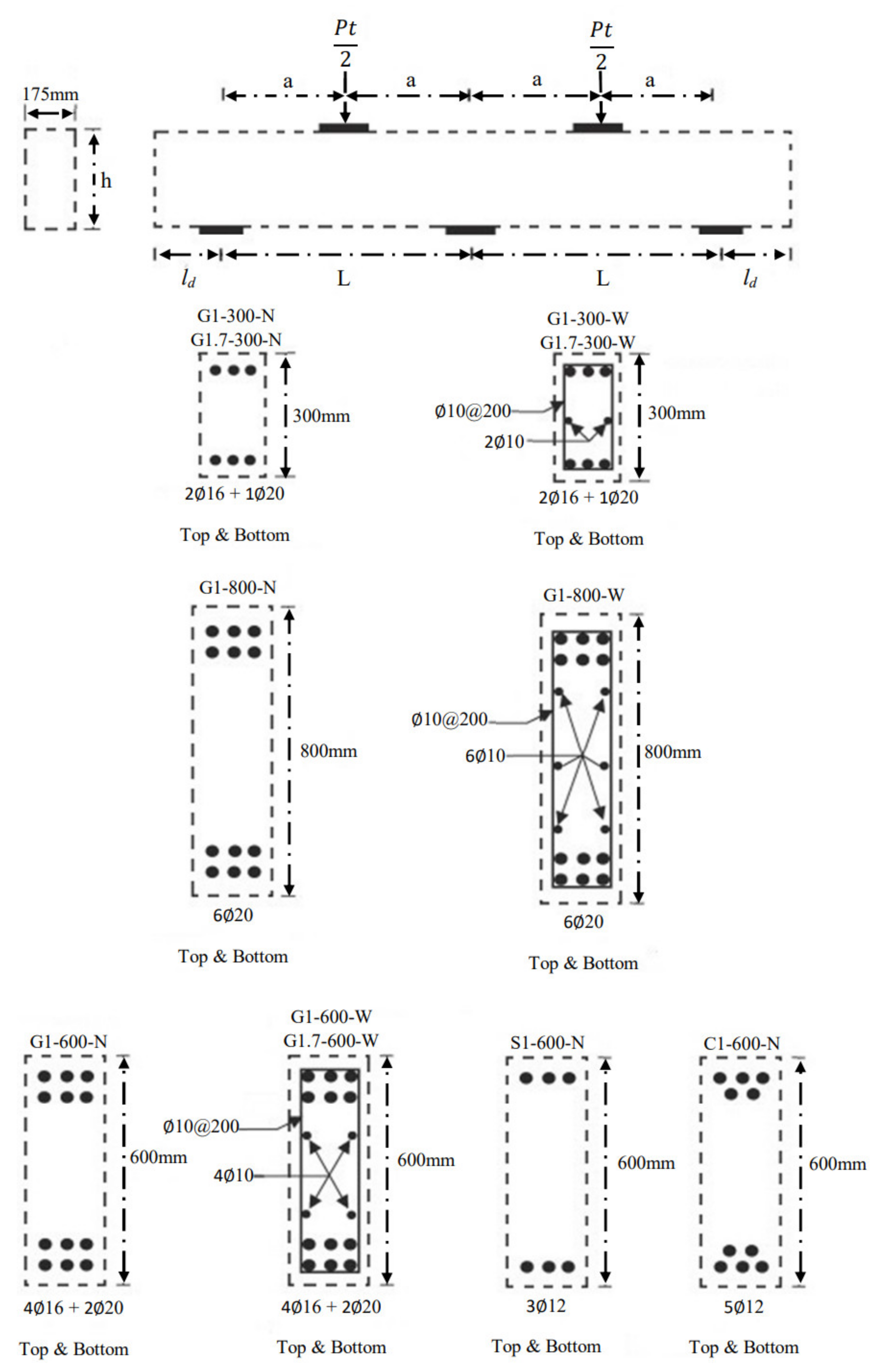
2.1. Details of Numerical Models
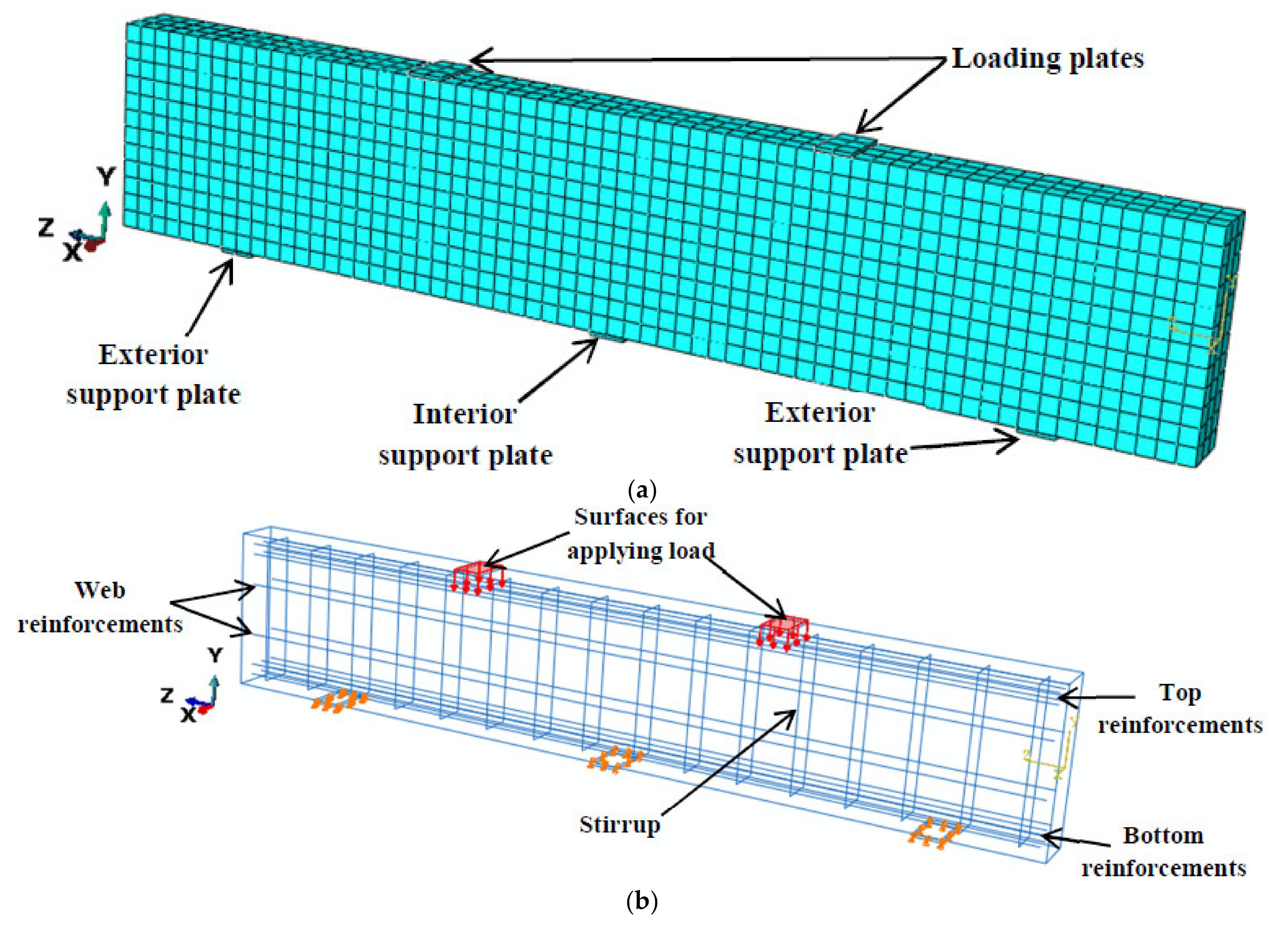
2.2. Features and Element Types of the Reinforced Concrete Deep Models
2.3. Material Properties
2.3.1. Reinforcements
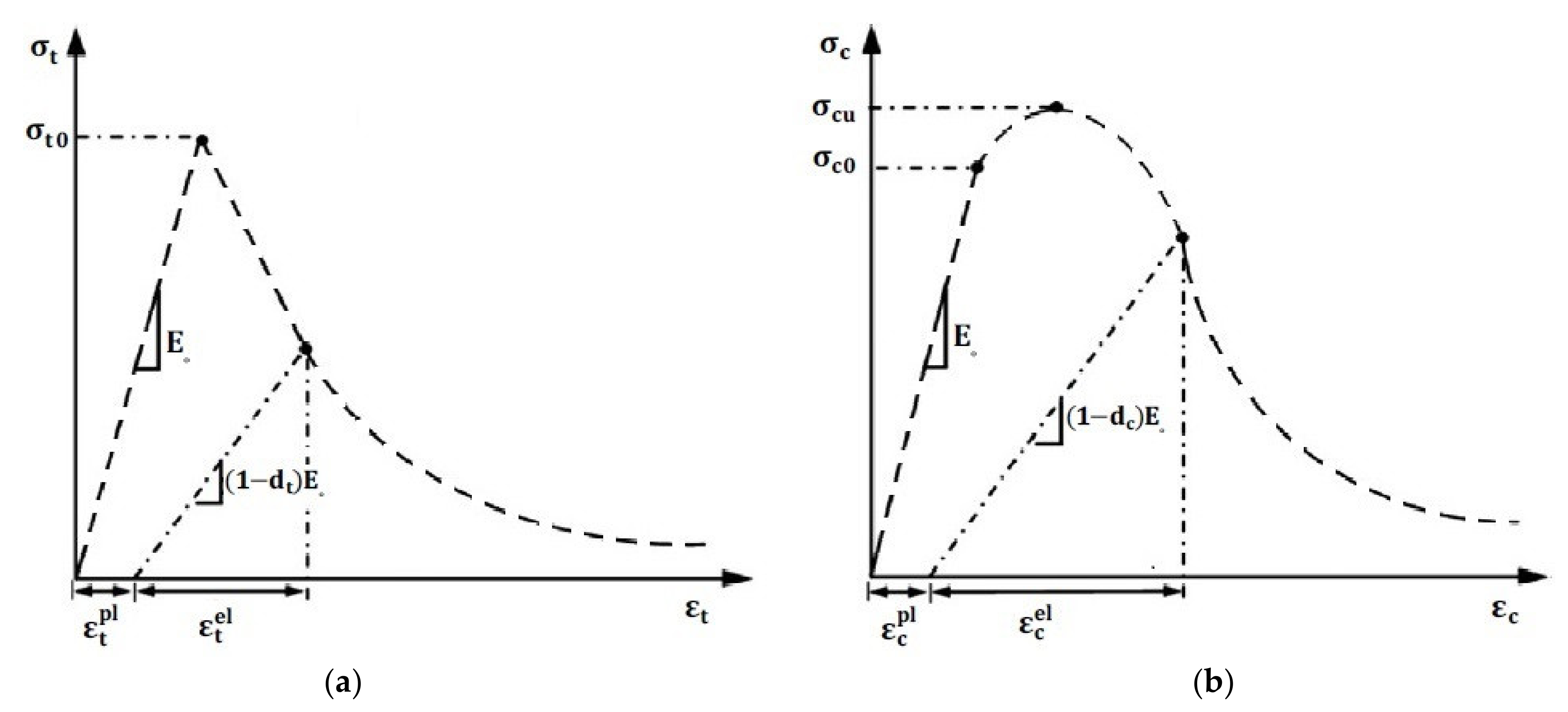
2.3.2. Concrete
3. Validation of Reinforced Concrete Deep Models
4. Results and Discussions
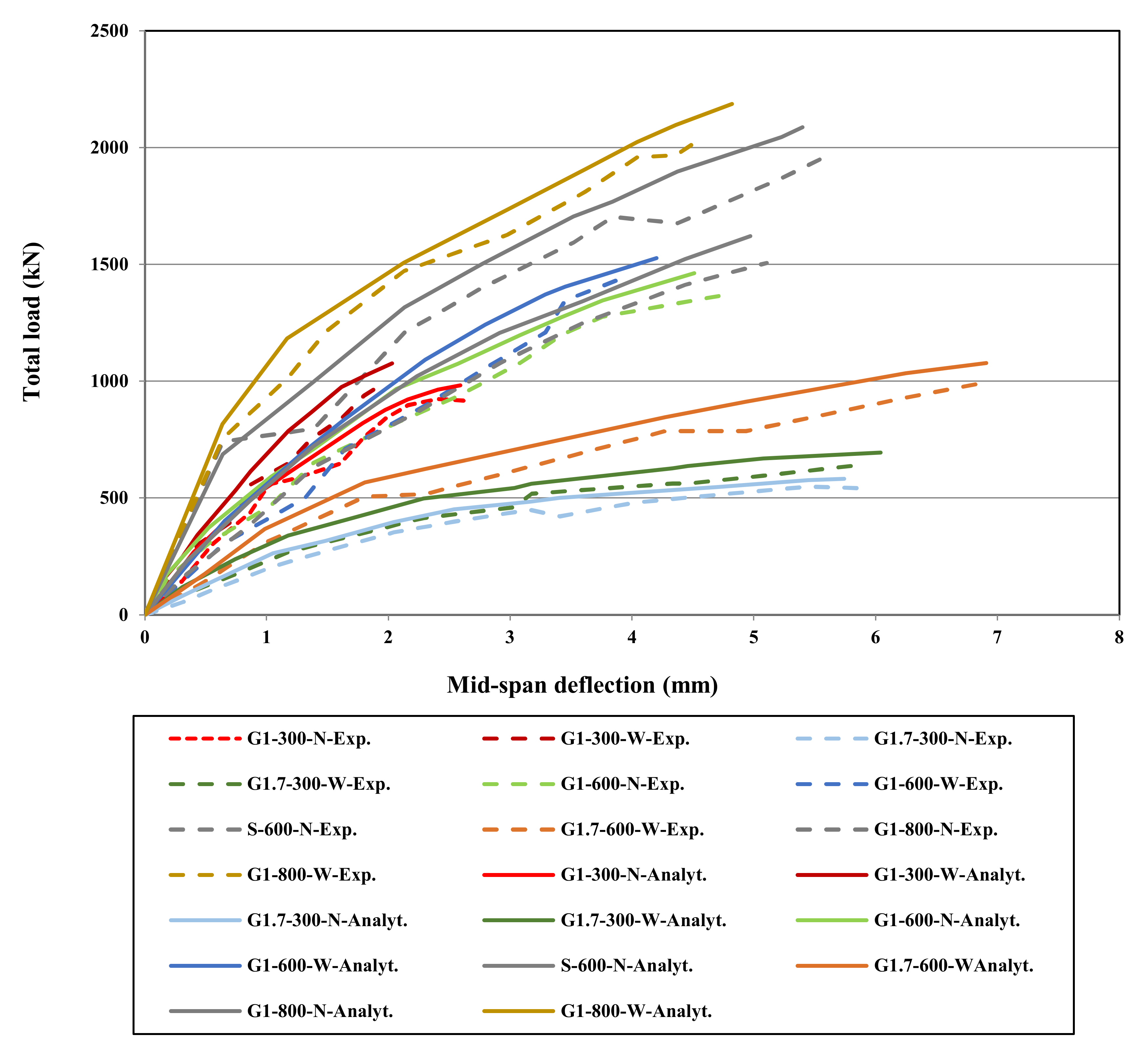
4.1. Flexural Performance of the Concrete Deep Beams with Different Heights
4.2. Non-Linear Performance of Deep Beams Strengthened with Web GFRP Rebars
4.3. Effect of a/h Ratio on the Stress Distribution in the Deep Beams
4.4. Effect of Steel, GFRP, and CFRP Longitudinal Reinforcements on the Non-Linear Performance of Deep Beams
4.5. Non-Linear Performance of the Deep Beams without Top Longitudinal Reinforcement
4.6. A Comparison between the GFRP Strengthened High- and Normal-Strength Concrete Deep Beams
5. Conclusions
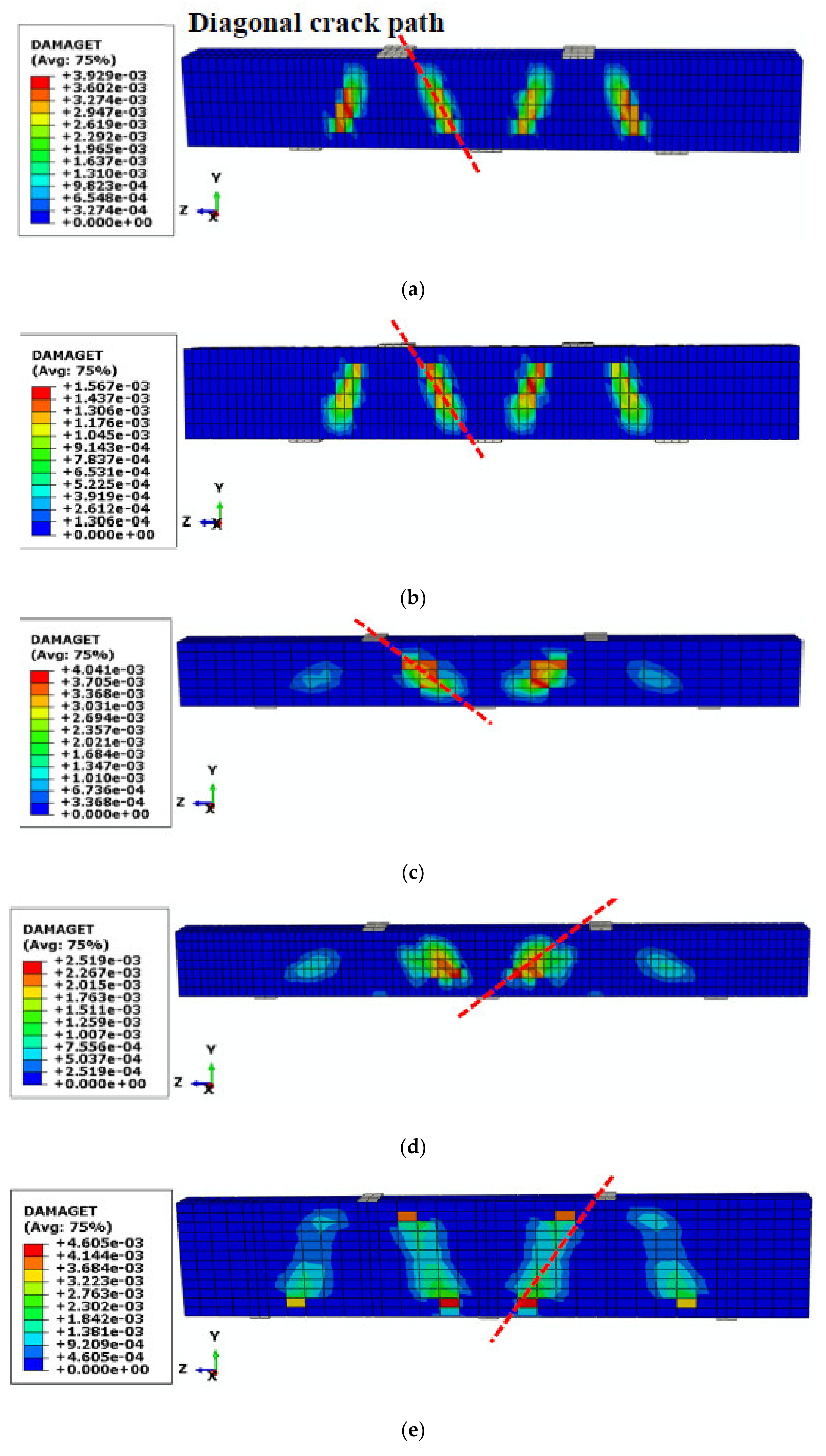
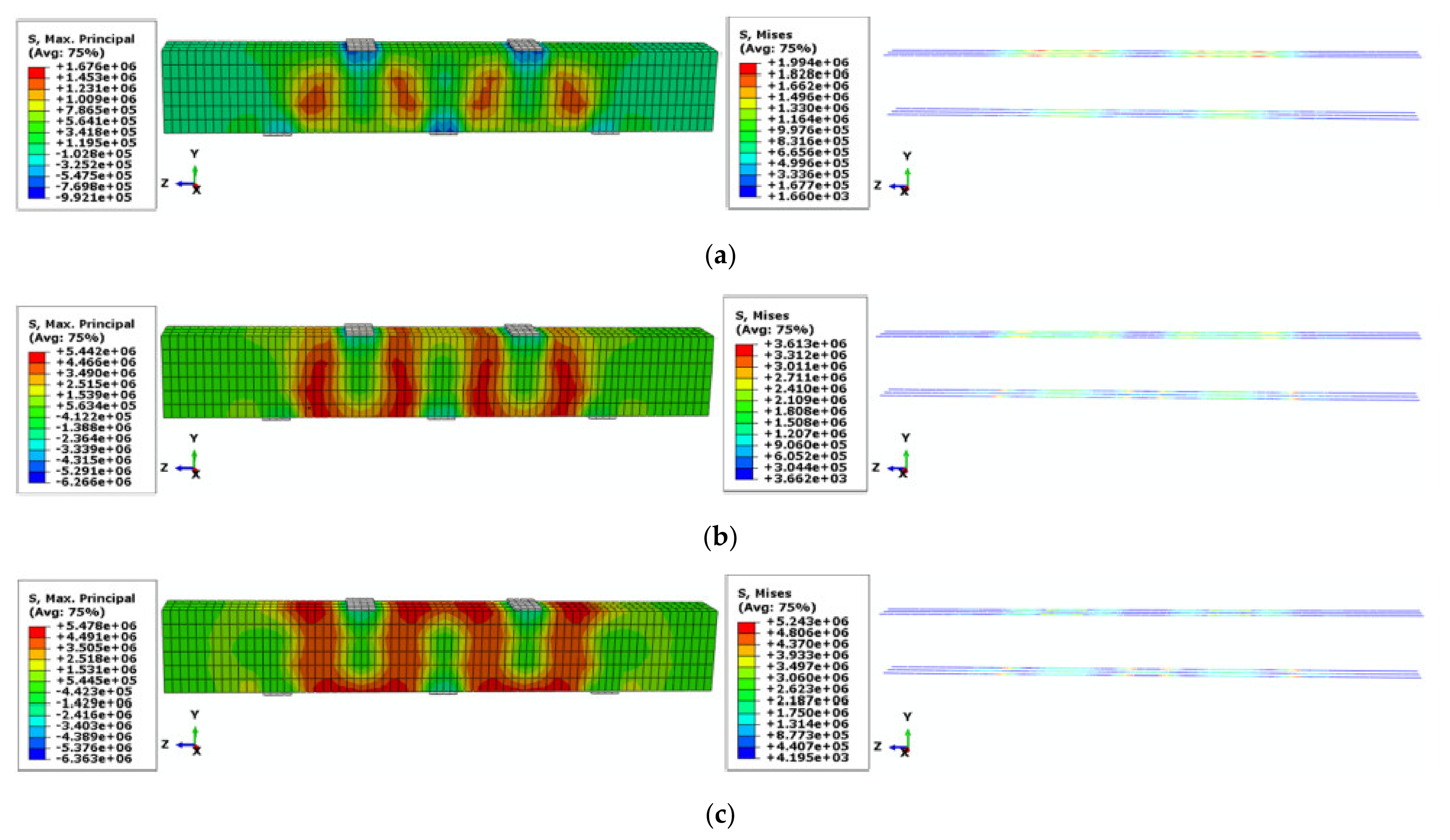
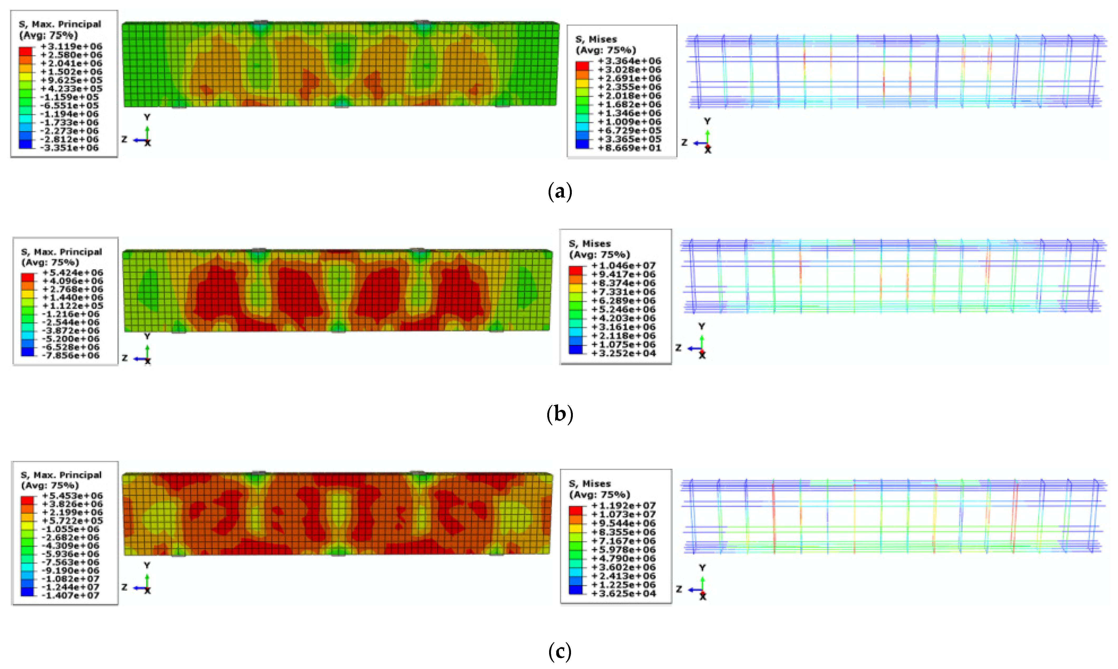
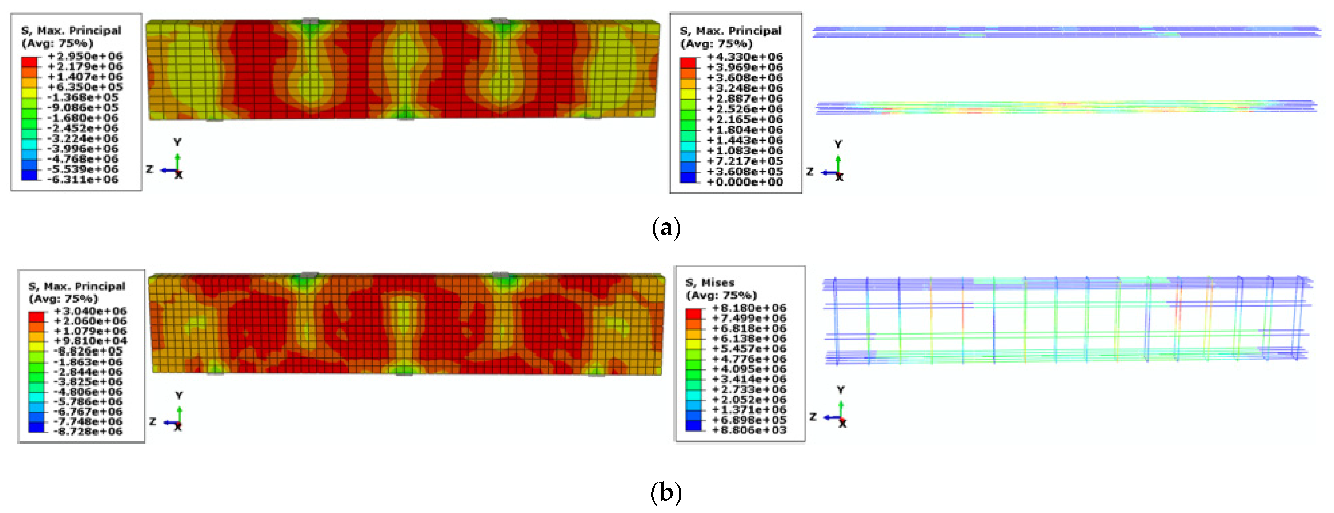
- The maximum tensile stress was propagated more in the bottom GFRP reinforcements than the top GFRP reinforcements by increasing the load. In addition, the highest dissipation of stress intensity along the beam length was observed for the concrete component with a height of 800 mm. Therefore, the participation of GFRP reinforcements and concrete component increased by increasing the height of concrete deep beams to carry the applied load.
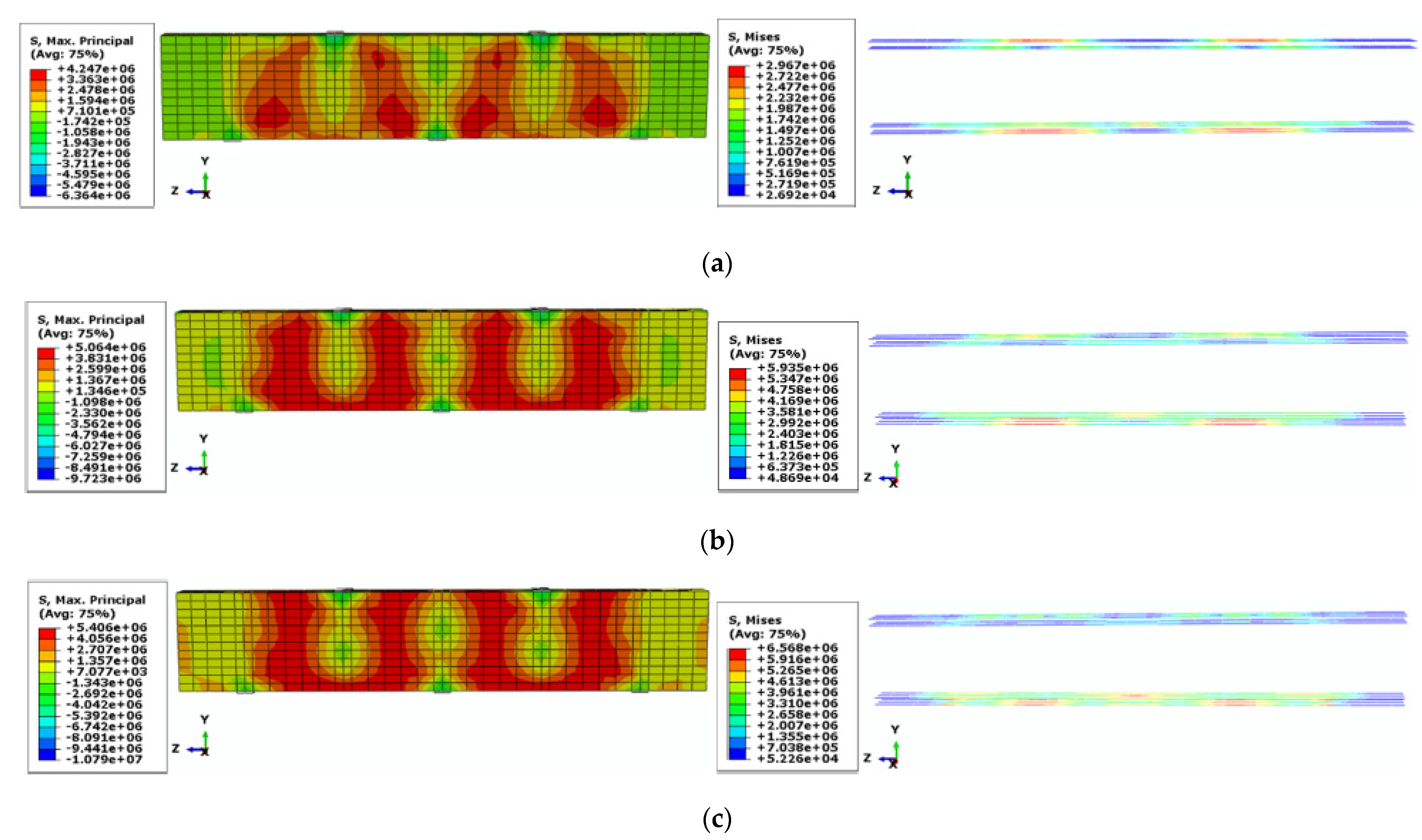
- The stress intensity in the concrete components was dissipated along the beam length more in the concrete deep beams with the web reinforcement than those with no web reinforcement. This intensity was dissipated more in the web reinforcement embedded near to the bottom reinforcement than that embedded near to the top reinforcement.
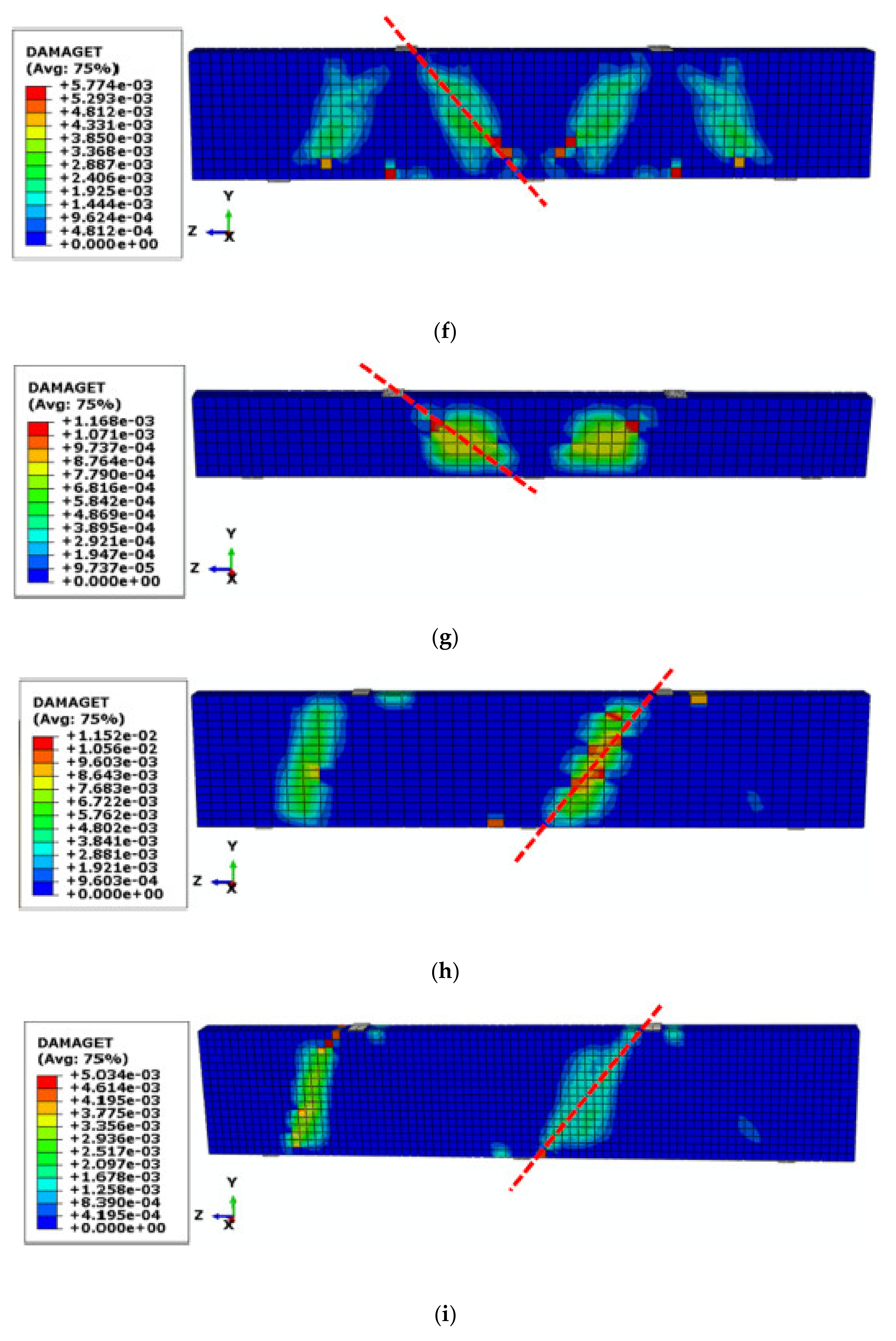
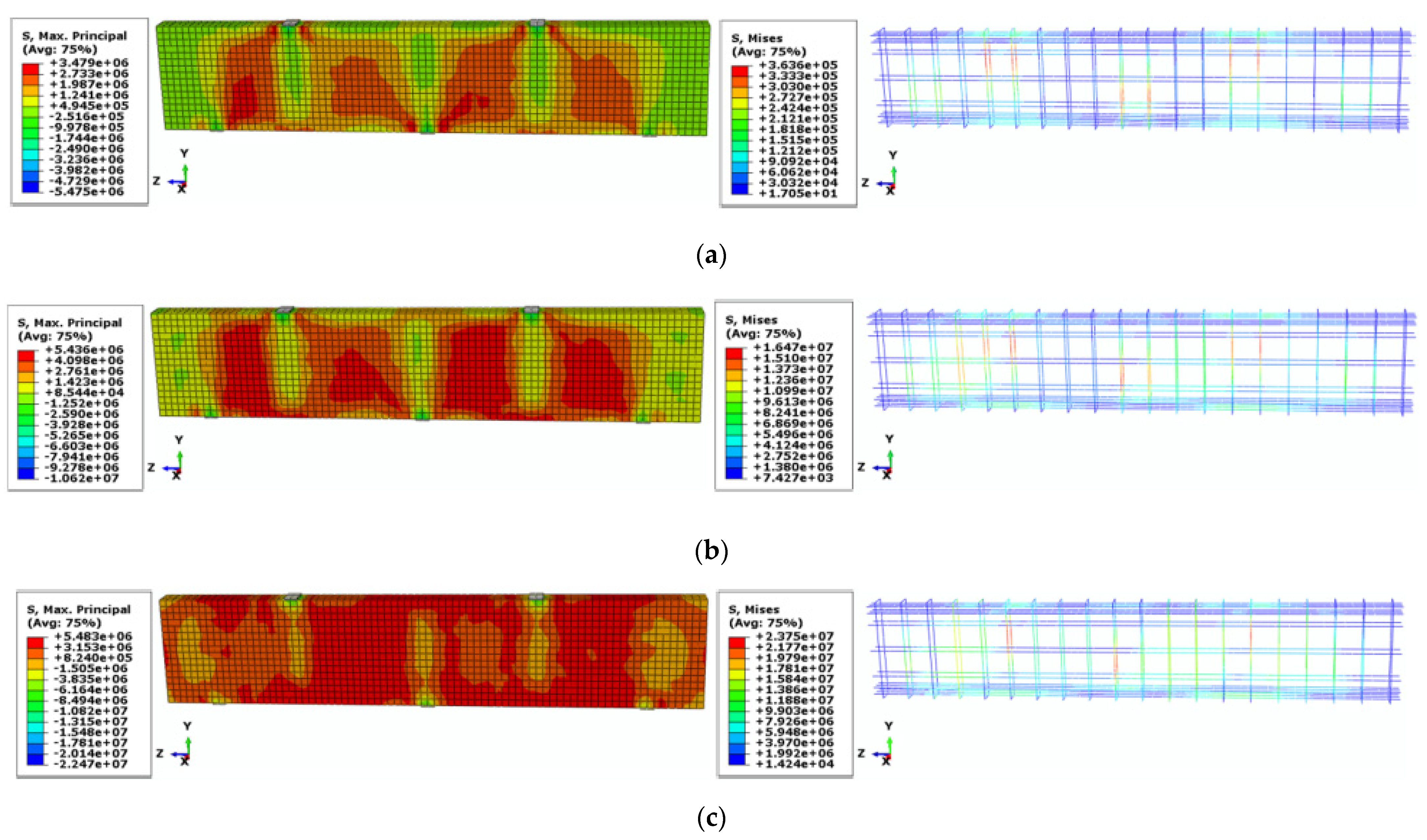
- The maximum tensile stress in the reinforcement of concrete deep beams with the web GFRP rebar under the failure load was obtained in the range of 11.9–23.7 MPa. The corresponding range for the reinforcement of concrete deep beams without the web rebar was 5.2–6.5 MPa. Therefore, the presence of web GFRP rebar increased the maximum tensile stress in the rebar component and subsequently enhanced the participation of the reinforcement and concrete component in carrying a higher amount of loading.
- By the presence of the web reinforcement and by increasing the height of the concrete deep beams, the participation of the combined reinforcement and concrete components in carrying the applied load increased for the concrete deep beams with a/h ratio of 1.7, but not as much as those with a/h ratio of 1.
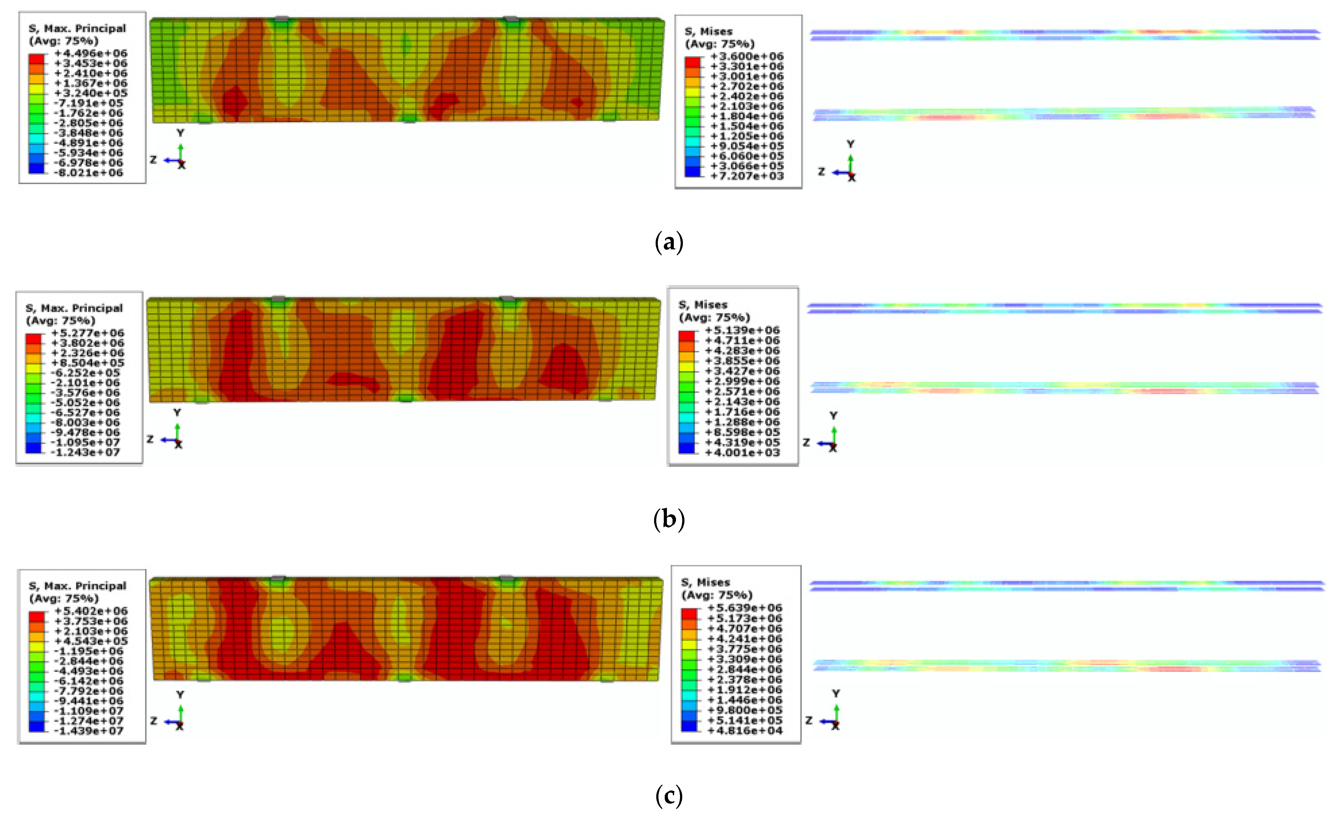
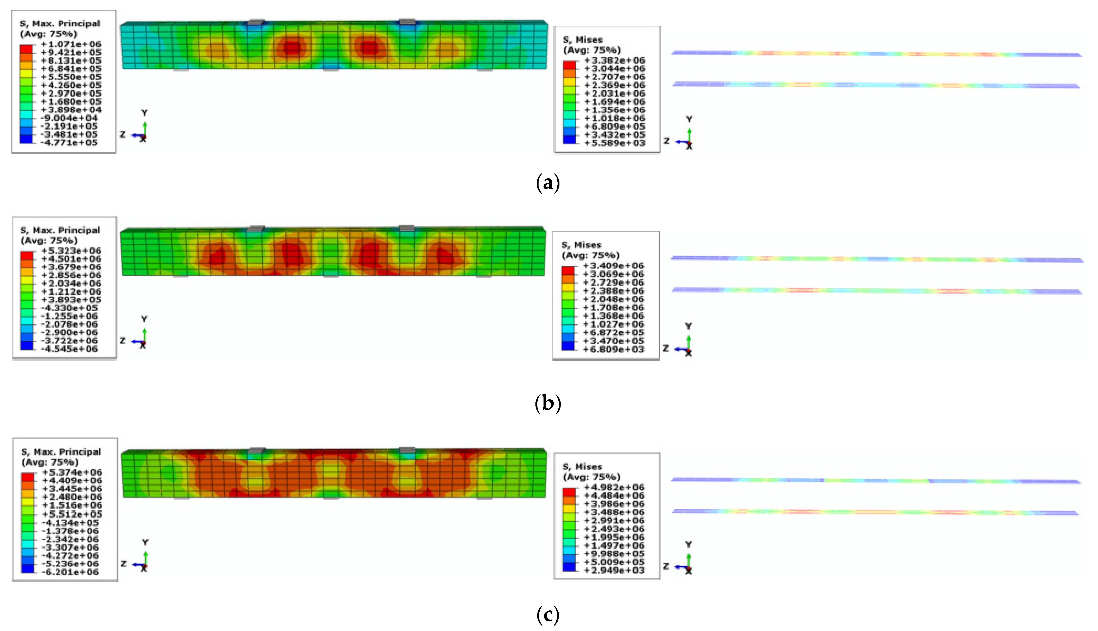
- By replacing the GFRP reinforcement with CFRP and steel reinforcements, the ultimate load-bearing resistance of concrete beams with the 600-mm height and without the web reinforcement increased up to 4.8% and 10.9%, respectively.
- The maximum tensile stresses in the GFRP, CFRP, and steel reinforcements were equal to 6.57, 16.2, and 23 MPa, respectively. Therefore, the highest tensile stress was obtained for the steel reinforcement and the tensile stress in the CFRP reinforcement was obtained more than that in the GFRP reinforcement under the failure load. In addition, the stress intensity in the concrete components of deep beams reinforced with the steel reinforcement (S1-600-N) was moderately dissipated along the beam length more than that in the concrete deep beams with the CFRP and GFRP reinforcements (C1-600-N and G1-600-N).
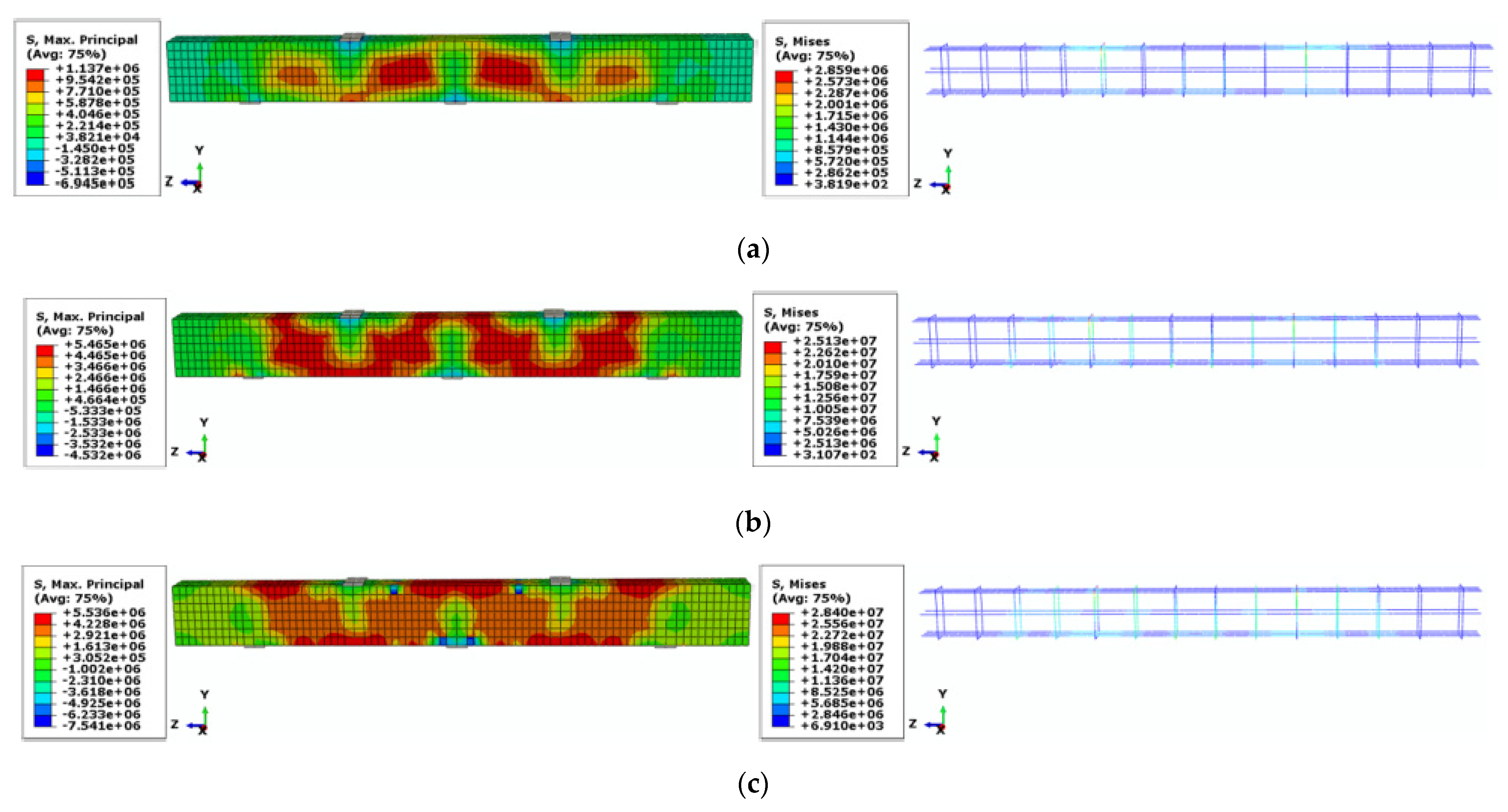
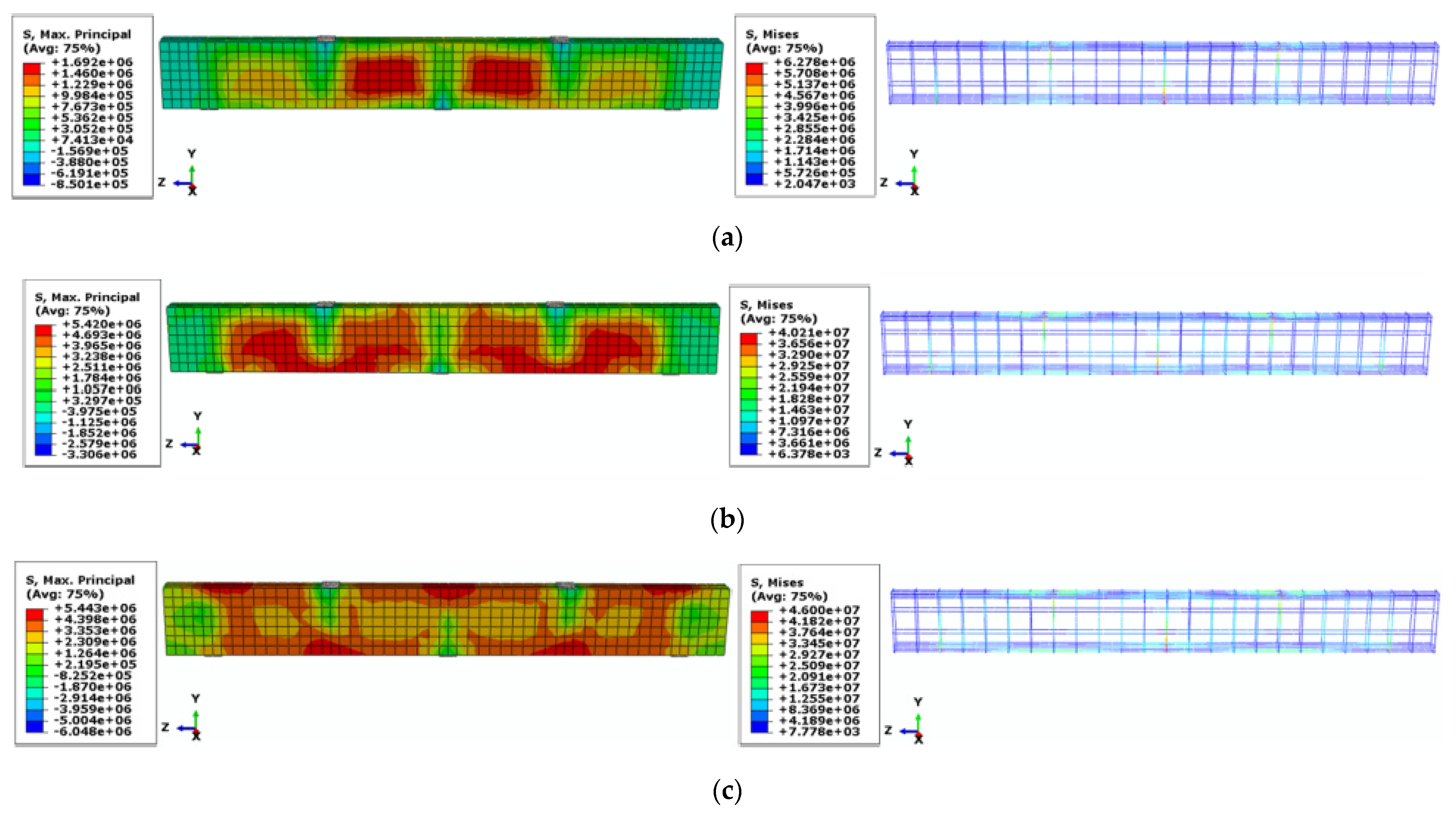
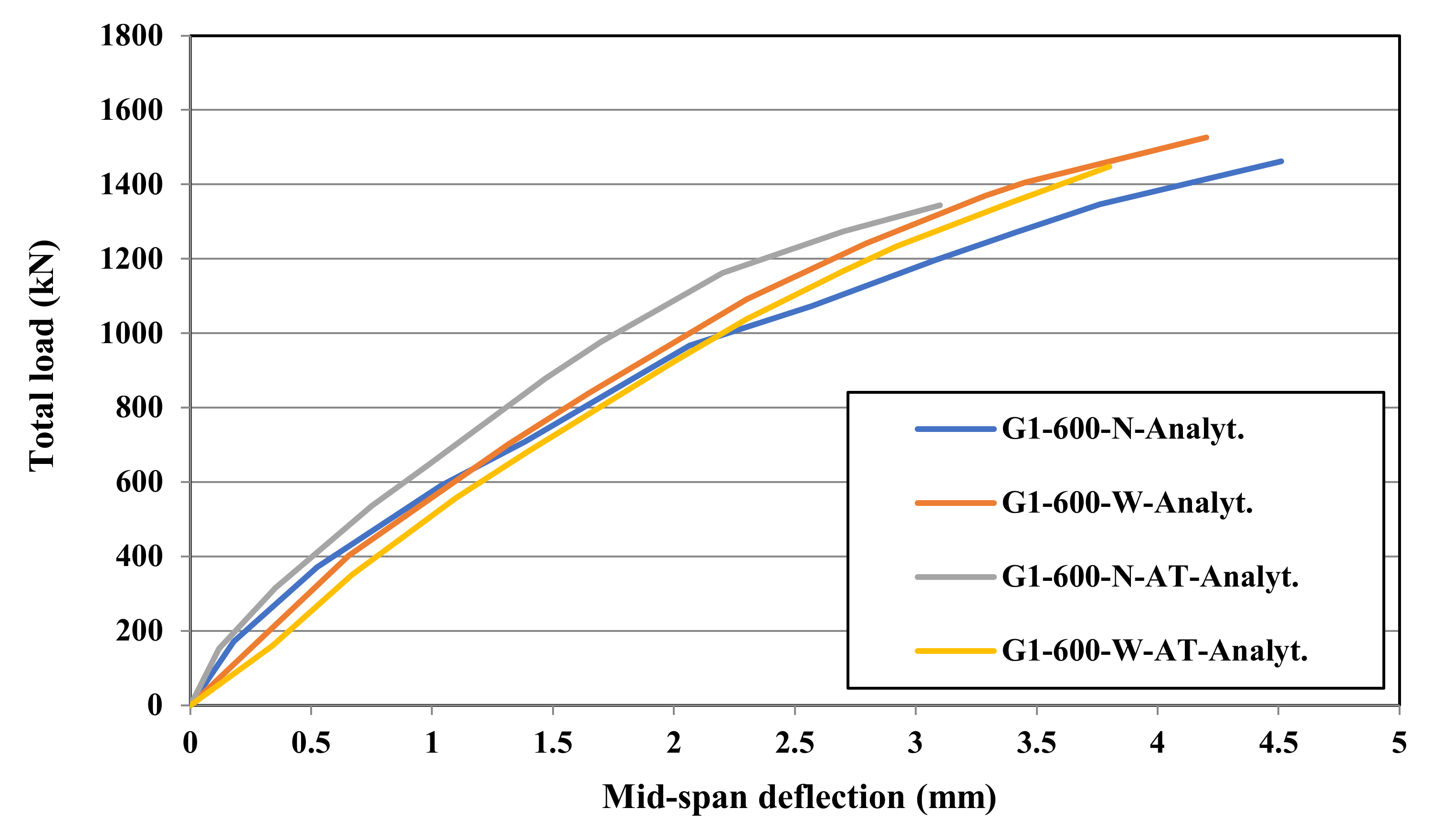
- With the absence of the web reinforcement, the failure load of the concrete deep beam with the top reinforcement (G1-600-N) was 8.7% more than that without the top reinforcement (G1-600-N-AT). The corresponding difference was 5.4% with the presence of the web reinforcement. Therefore, the web reinforcement slightly compensated for the absence of the top rebar to reinforce the concrete deep beams in carrying the ultimate load.
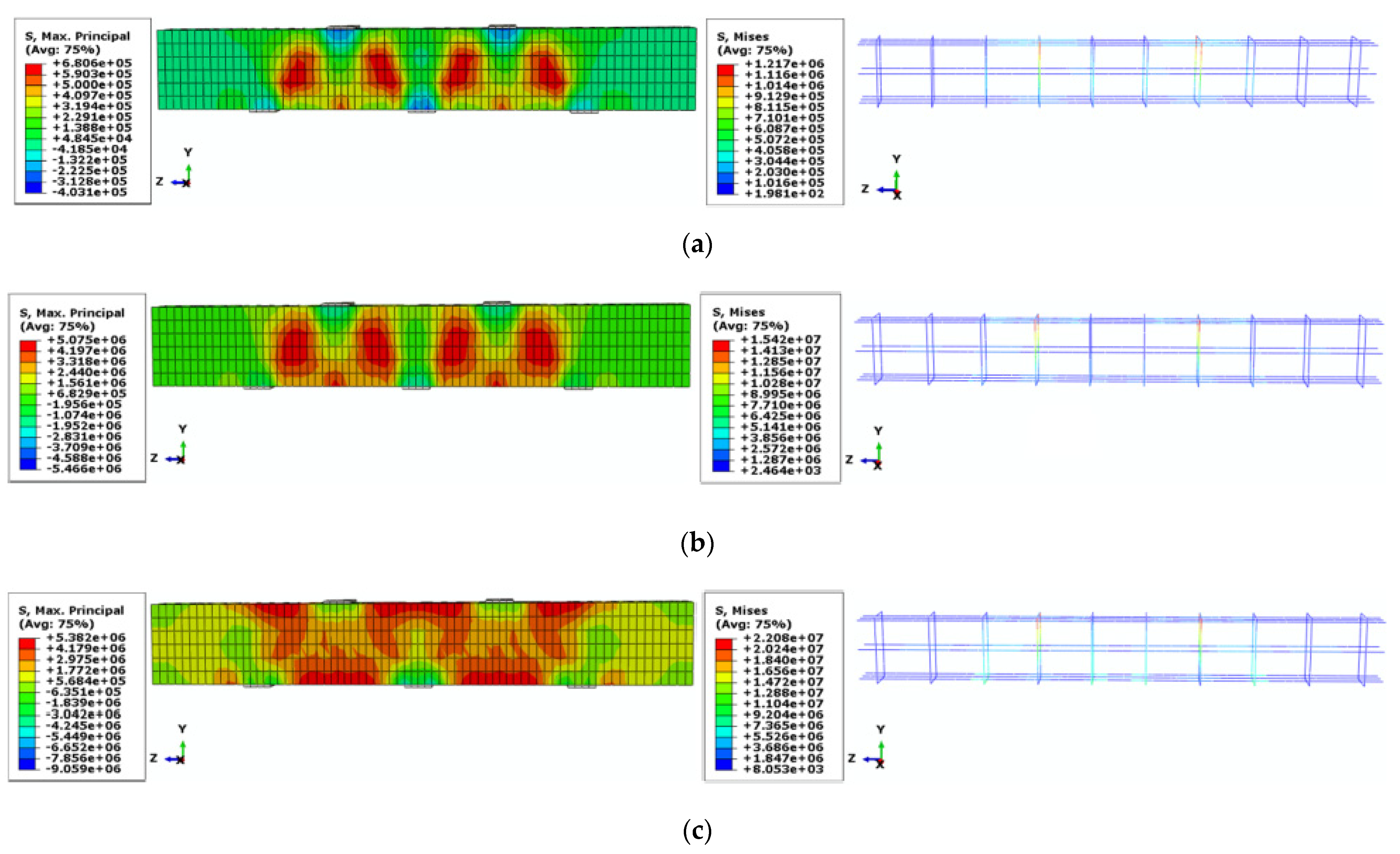
- The maximum tensile stress distribution along the beam length of the concrete component without the top reinforcement was not as much as that of the concrete component with the top reinforcement. In addition, with the absence of the top reinforcement, the maximum tensile stress was dissipated more in the concrete deep beam with the web rebar than that without the web rebar.
- With the absence of the top reinforcement, the stress intensity in the web reinforcement embedded near to the top reinforcement was more than that near to the bottom reinforcement, contrarily to the concrete deep beams with the presence of the top reinforcement.
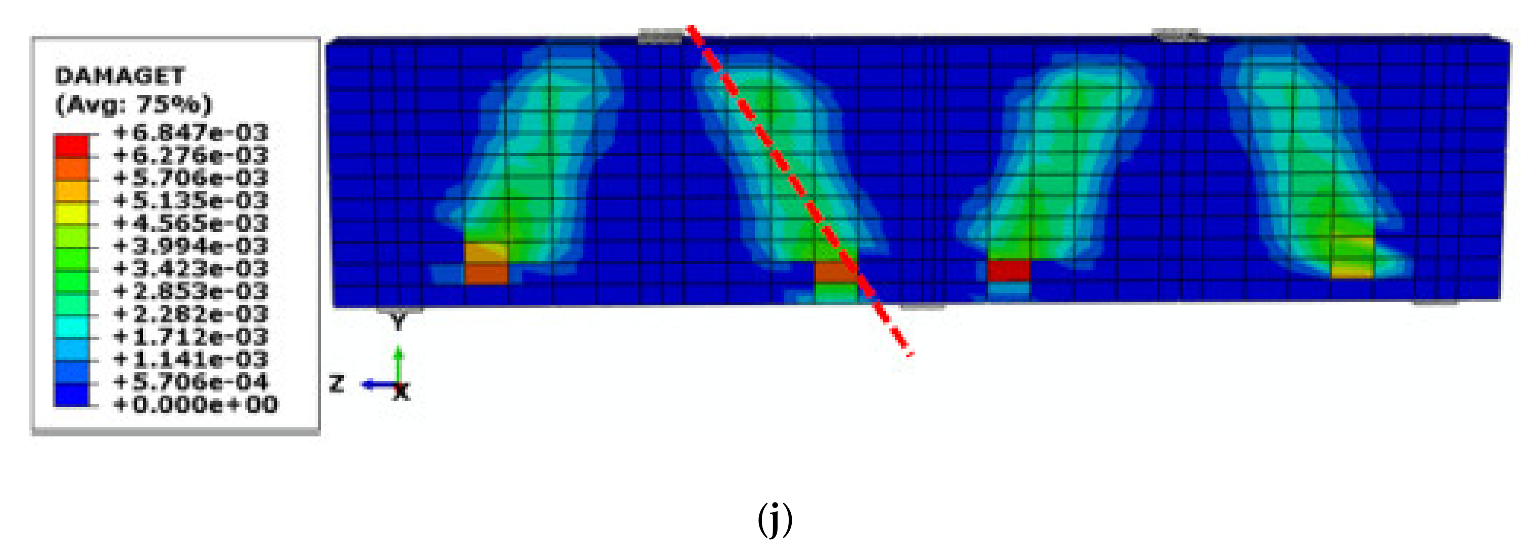
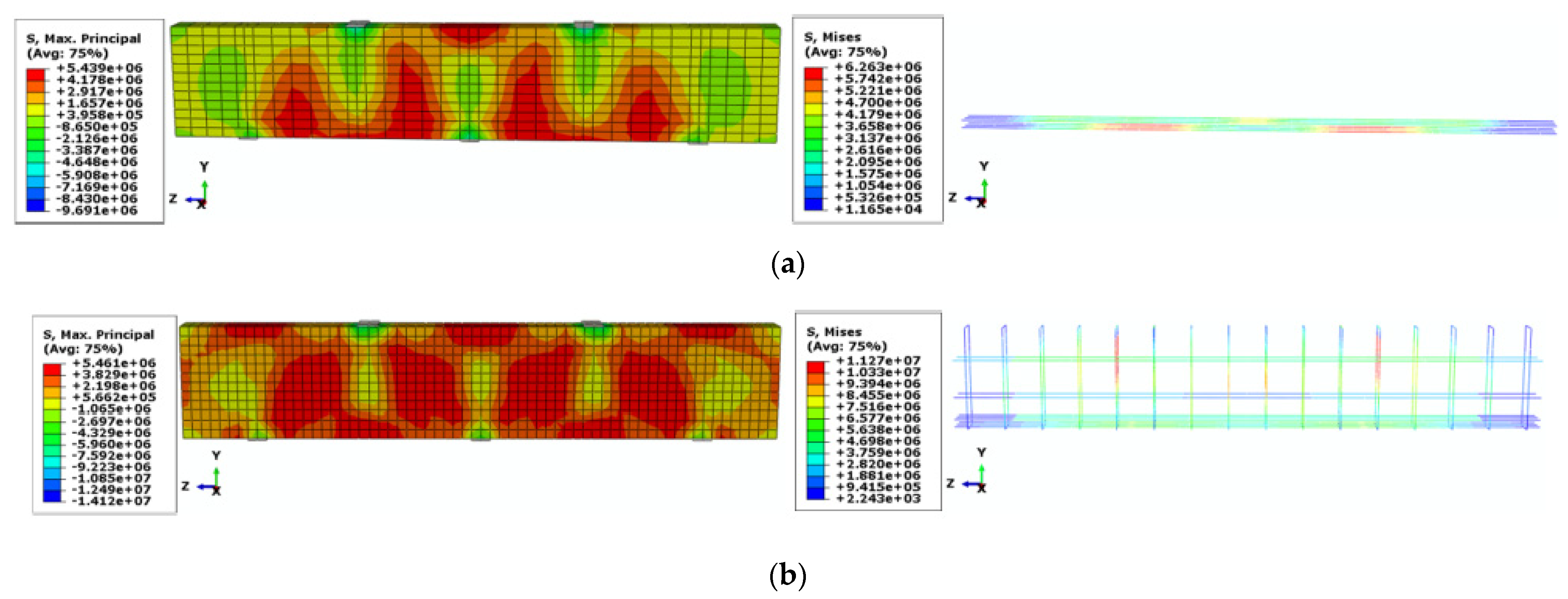
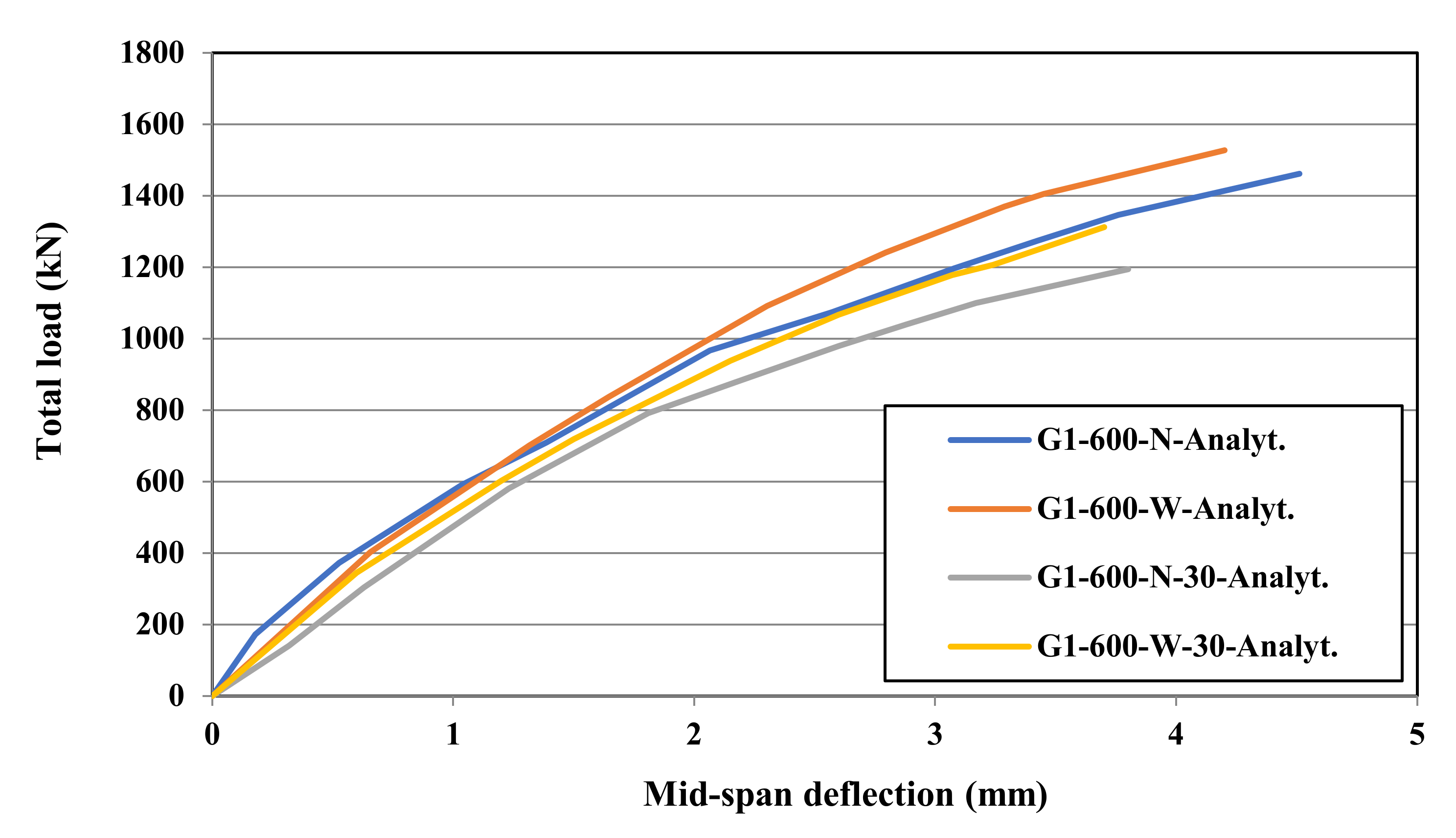
- The difference between the results of high- and normal-strength concrete deep beams with the web reinforcement (16.4%) was lower than that without the web reinforcement (22.3%). Therefore, the web reinforcement moderately compensated for the low strength of the normal concrete in strengthening the deep beams in carrying the ultimate load.
- The maximum tensile stresses in the reinforcement of the high-strength concrete deep beams were 45.7% and 51.5% more than those of the high-strength concrete deep beams with the presence and absence of the web reinforcement, respectively. Therefore, the participation of the GFRP reinforcement with the high-strength concrete was more than that with the normal-strength concrete in carrying a higher amount of loading.
Author Contributions
Funding
Institutional Review Board Statement
Informed Consent Statement
Data Availability Statement
Conflicts of Interest
References
- Abed, F.; El-Chabib, H.; AlHamaydeh, M. Shear Characteristics of GFRP-Reinforced Concrete Deep Beams without Web Reinforcement. J. Reinf. Plast. Compos. 2012, 31, 1063–1073. [Google Scholar] [CrossRef]
- Kachouh, N.; El-Maaddawy, T.; El-Hassan, H.; El-Ariss, B. Shear Response of Recycled Aggregates Concrete Deep Beams Containing Steel Fibers and Web Openings. Sustainability 2022, 14, 945. [Google Scholar] [CrossRef]
- Fang, Q.; Wang, G.; Yu, F.; Du, J. Analytical Algorithm for Longitudinal Deformation Profile of a Deep Tunnel. J. Rock Mech. Geotech. Eng. 2021, 13, 845–854. [Google Scholar] [CrossRef]
- Jarrah, M.; Najafabadi, E.P.; Khaneghahi, M.H.; Oskouei, A.V. The Effect of Elevated Temperatures on the Tensile Performance of GFRP and CFRP Sheets. Constr. Build. Mater. 2018, 190, 38–52. [Google Scholar] [CrossRef]
- Kazemi, M.; Li, J.; Harehdasht, S.L.; Yousefieh, N.; Jahandari, S.; Saberian, M. Non-Linear Behaviour of Concrete Beams Reinforced with GFRP and CFRP Bars Grouted in Sleeves. In Proceedings of the Structures; Elsevier: Amsterdam, The Netherlands, 2020; Volume 23, pp. 87–102. [Google Scholar]
- Rahif, R.; Amaripadath, D.; Attia, S. Review on Time-Integrated Overheating Evaluation Methods for Residential Buildings in Temperate Climates of Europe. Energy Build. 2021, 252, 111463. [Google Scholar] [CrossRef]
- Kazemi, M.; Courard, L.; Hubert, J. Coarse Recycled Materials for the Drainage and Substrate Layers of Green Roof System in Dry Condition: Parametric Study and Thermal Heat Transfer. J. Build. Eng. 2022, 45, 103487. [Google Scholar] [CrossRef]
- Kazemi, M.; Courard, L.; Hubert, J. Heat Transfer Measurement within Green Roof with Incinerated Municipal Solid Waste Aggregates. Sustainability 2021, 13, 7115. [Google Scholar] [CrossRef]
- Kazemi, M.; Courard, L. Modelling Hygrothermal Conditions of Unsaturated Substrate and Drainage Layers for the Thermal Resistance Assessment of Green Roof: Effect of Coarse Recycled Materials. Energy Build. 2021, 250, 111315. [Google Scholar] [CrossRef]
- Pilechiha, P.; Norouziasas, A.; Ghorbani Naeini, H.; Jolma, K. Evaluation of Occupant’s Adaptive Thermal Comfort Behaviour in Naturally Ventilated Courtyard Houses. Smart Sustain. Built Environ. 2021. ahead-of-print. [Google Scholar] [CrossRef]
- Miraki, H.; Shariatmadari, N.; Ghadir, P.; Jahandari, S.; Tao, Z.; Siddique, R. Clayey Soil Stabilization Using Alkali-Activated Volcanic Ash and Slag. J. Rock Mech. Geotech. Eng. 2021, 14, 1–16. [Google Scholar] [CrossRef]
- Hataf, N.; Ghadir, P.; Ranjbar, N. Investigation of Soil Stabilization Using Chitosan Biopolymer. J. Clean. Prod. 2018, 170, 1493–1500. [Google Scholar] [CrossRef]
- Mou, B.; Bai, Y. Experimental Investigation on Shear Behavior of Steel Beam-to-CFST Column Connections with Irregular Panel Zone. Eng. Struct. 2018, 168, 487–504. [Google Scholar] [CrossRef]
- Sinaei, H.; Jumaat, M.Z.; Shariati, M. Numerical Investigation on Exterior Reinforced Concrete Beam-Column Joint Strengthened by Composite Fiber Reinforced Polymer (CFRP). Int. J. Phys. Sci. 2011, 6, 6572–6579. [Google Scholar]
- Zhang, C.; Abedini, M. Development of P-I Model for FRP Composite Retrofitted RC Columns Subjected to High Strain Rate Loads Using LBE Function. Eng. Struct. 2022, 252, 113580. [Google Scholar] [CrossRef]
- Huang, H.; Xue, C.; Zhang, W.; Guo, M. Torsion Design of CFRP-CFST Columns Using a Data-Driven Optimization Approach. Eng. Struct. 2022, 251, 113479. [Google Scholar] [CrossRef]
- Wei, J.; Xie, Z.; Zhang, W.; Luo, X.; Yang, Y.; Chen, B. Experimental Study on Circular Steel Tube-Confined Reinforced UHPC Columns under Axial Loading. Eng. Struct. 2021, 230, 111599. [Google Scholar] [CrossRef]
- Sajedi, F.; Shariati, M. Behavior Study of NC and HSC RCCs Confined by GRP Casing and CFRP Wrapping. Steel Compos. Struct 2019, 30, 417–432. [Google Scholar]
- Xiao, X.; Bu, G.; Ou, Z.; Li, Z. Nonlinear In-Plane Instability of the Confined FGP Arches with Nanocomposites Reinforcement under Radially-Directed Uniform Pressure. Eng. Struct. 2022, 252, 113670. [Google Scholar] [CrossRef]
- Sadeghian, F.; Haddad, A.; Jahandari, S.; Rasekh, H.; Ozbakkaloglu, T. Effects of Electrokinetic Phenomena on the Load-Bearing Capacity of Different Steel and Concrete Piles: A Small-Scale Experimental Study. Can. Geotech. J. 2021, 58, 741–746. [Google Scholar] [CrossRef]
- Cheng, H.; Sun, L.; Wang, Y.; Chen, X. Effects of Actual Loading Waveforms on the Fatigue Behaviours of Asphalt Mixtures. Int. J. Fatigue 2021, 151, 106386. [Google Scholar] [CrossRef]
- Dong, J.; Deng, R.; Quanying, Z.; Cai, J.; Ding, Y.; Li, M. Research on Recognition of Gas Saturation in Sandstone Reservoir Based on Capture Mode. Appl. Radiat. Isot. 2021, 178, 109939. [Google Scholar] [CrossRef] [PubMed]
- Roudi, A.; Chelliapan, S.; Kamyab, H.; Md Din, M.F.; Krishnan, S. Removal of COD from Landfill Leachate by Predication and Evaluation of Multiple Linear Regression (MLR) Model and Fenton Process. Egypt. J. Chem. 2019, 62, 1207–1218. [Google Scholar] [CrossRef]
- Zhang, S.; Pak, R.Y.S.; Zhang, J. Three-Dimensional Frequency-Domain Green’s Functions of a Finite Fluid-Saturated Soil Layer Underlain by Rigid Bedrock to Interior Loadings. Int. J. Geomech. 2022, 22, 04021267. [Google Scholar] [CrossRef]
- Lu, N.; Wang, H.; Wang, K.; Liu, Y. Maximum Probabilistic and Dynamic Traffic Load Effects on Short-to-Medium Span Bridges. Comput. Modeling Eng. Sci. 2021, 127, 345–360. [Google Scholar] [CrossRef]
- Zhang, H.; Liu, Y.; Deng, Y. Temperature Gradient Modeling of a Steel Box-Girder Suspension Bridge Using Copulas Probabilistic Method and Field Monitoring. Adv. Struct. Eng. 2021, 24, 947–961. [Google Scholar] [CrossRef]
- Xiang, G.X.; Gao, X.; Tang, W.J.; Jie, X.Z.; Huang, X. Numerical Study on Transition Structures of Oblique Detonations with Expansion Wave from Finite-Length Cowl. Phys. Fluids 2020, 32, 056108. [Google Scholar] [CrossRef]
- Akbarzadeh Bengar, H.; Shahmansouri, A.A. A New Anchorage System for CFRP Strips in Externally Strengthened RC Continuous Beams. J. Build. Eng. 2020, 30, 101230. [Google Scholar] [CrossRef]
- Kazemi, M.; Madandoust, R.; Chastre, C.; Reza Esfahani, M.; Courard, L. Numerical Study on the Flexural Behaviour of Normal- and High-Strength Concrete Beams Reinforced with GFRP Bar, Using Different Amounts of Transverse Reinforcement. Structures 2021, 34, 3113–3124. [Google Scholar] [CrossRef]
- Yousefi Moghadam, S.; Ranjbar, M.M.; Madandoust, R.; Kazemi, M. Analytical Study on the Behavior of Corrosion-Damaged Reinforced Concrete Beams Strengthen with FRP. Rev. Romana De Mater. 2017, 47, 514–521. [Google Scholar]
- Godat, A.; Alghafri, E.; Al Tamimi, N.; Aljaberi, H.; Aldaweela, S. Bond Behavior of Basalt Fiber Reinforced Polymer Bars in Recycled Coarse Aggregate Concrete. Sustainability 2022, 14, 1374. [Google Scholar] [CrossRef]
- Tang, Y.; Sun, Z.; Wu, G. Compressive Behavior of Sustainable Steel-FRP Composite Bars with Different Slenderness Ratios. Sustainability 2019, 11, 1118. [Google Scholar] [CrossRef] [Green Version]
- Abraik, E.; Youssef, M.A.; El-Fitiany, S.F. Seismic Performance of Hybrid Corrosion-Free Self-Centering Concrete Shear Walls. Sustainability 2022, 14, 712. [Google Scholar] [CrossRef]
- Ju, M.; Park, Y.; Park, C. Cracking Control Comparison in the Specifications of Serviceability in Cracking for FRP Reinforced Concrete Beams. Compos. Struct. 2017, 182, 674–684. [Google Scholar] [CrossRef]
- Mohammed, A.A.; Manalo, A.C.; Ferdous, W.; Zhuge, Y.; Vijay, P.V.; Alkinani, A.Q.; Fam, A. State-of-the-Art of Prefabricated FRP Composite Jackets for Structural Repair. Eng. Sci. Technol. Int. J. 2020, 23, 1244–1258. [Google Scholar] [CrossRef]
- Bencardino, F.; Condello, A.; Ombres, L. Numerical and Analytical Modeling of Concrete Beams with Steel, FRP and Hybrid FRP-Steel Reinforcements. Compos. Struct. 2016, 140, 53–65. [Google Scholar] [CrossRef]
- Luo, Z.; Sinaei, H.; Ibrahim, Z.; Shariati, M.; Jumaat, Z.; Wakil, K.; Pham, B.T.; Mohamad, E.T.; Khorami, M. Computational and Experimental Analysis of Beam to Column Joints Reinforced with CFRP Plates. Steel Compos. Struct. 2019, 30, 271–280. [Google Scholar]
- Zhang, L.; Sun, Y.; Xiong, W. Experimental Study on the Flexural Deflections of Concrete Beam Reinforced with Basalt FRP Bars. Mater. Struct. 2015, 48, 3279–3293. [Google Scholar] [CrossRef]
- Adam, M.A.; Said, M.; Mahmoud, A.A.; Shanour, A.S. Analytical and Experimental Flexural Behavior of Concrete Beams Reinforced with Glass Fiber Reinforced Polymers Bars. Constr. Build. Mater. 2015, 84, 354–366. [Google Scholar] [CrossRef]
- Okelo, R.; Yuan, R.L. Bond Strength of Fiber Reinforced Polymer Rebars in Normal Strength Concrete. J. Compos. Constr. 2005, 9, 203–213. [Google Scholar] [CrossRef]
- Lee, J.-Y.; Kim, T.-Y.; Kim, T.-J.; Yi, C.-K.; Park, J.-S.; You, Y.-C.; Park, Y.-H. Interfacial Bond Strength of Glass Fiber Reinforced Polymer Bars in High-Strength Concrete. Compos. Part B: Eng. 2008, 39, 258–270. [Google Scholar] [CrossRef]
- Farghaly, A.S.; Benmokrane, B. Shear Behavior of FRP-Reinforced Concrete Deep Beams without Web Reinforcement. J. Compos. Constr. 2013, 17, 04013015. [Google Scholar] [CrossRef]
- Andermatt, M.F.; Lubell, A.S. Behavior of Concrete Deep Beams Reinforced with Internal Fiber-Reinforced Polymer-Experimental Study. ACI Struct. J. 2013, 110, 585. [Google Scholar]
- Chen, H.; Yi, W.-J.; Ma, Z.J.; Hwang, H.-J. Modeling of Shear Mechanisms and Strength of Concrete Deep Beams Reinforced with FRP Bars. Compos. Struct. 2020, 234, 111715. [Google Scholar] [CrossRef]
- Mohamed, A.M.; Mahmoud, K.; El-Salakawy, E.F. Behavior of Simply Supported and Continuous Concrete Deep Beams Reinforced with GFRP Bars. J. Compos. Constr. 2020, 24, 04020032. [Google Scholar] [CrossRef]
- Zinkaah, O.H.; Ashour, A. Load Capacity Predictions of Continuous Concrete Deep Beams Reinforced with GFRP Bars. Structures 2019, 19, 449–462. [Google Scholar] [CrossRef] [Green Version]
- Thomas, J.; Ramadass, S. Prediction of the Load and Deflection Response of Concrete Deep Beams Reinforced with FRP Bars. Mech. Adv. Mater. Struct. 2021, 28, 43–66. [Google Scholar] [CrossRef]
- Mohamed, K.; Farghaly, A.S.; Benmokrane, B. Effect of Web Reinforcement in FRP-Reinforced Deep Beams. In Proceedings of the The 7th International Conference on FRP Composites in Civil Engineering, Vancouver, BC, Canada, 20–22 August 2014. [Google Scholar]
- Ashour, A.F. Shear Capacity of Reinforced Concrete Deep Beams. J. Struct. Eng. 2000, 126, 1045–1052. [Google Scholar] [CrossRef]
- Zinkaah, O.H.; Ashour, A.; Sheehan, T. Experimental Tests of Two-Span Continuous Concrete Deep Beams Reinforced with GFRP Bars and Strut-and-Tie Method Evaluation. Compos. Struct. 2019, 216, 112–126. [Google Scholar] [CrossRef]
- Madandoust, R.; Kazemi, M. Numerical Analysis of Break-off Test Method on Concrete. Constr. Build. Mater. 2017, 151, 487–493. [Google Scholar] [CrossRef]
- Kazemi, M.; Kafi, M.A.; Hajforoush, M.; Kheyroddin, A. Cyclic Behaviour of Steel Ring Filled with Compressive Plastic or Concrete, Installed in the Concentric Bracing System. Asian J. Civ. Eng. 2020, 21, 29–39. [Google Scholar] [CrossRef]
- Madandoust, R.; Bazkiyaei, Z.F.Z.; Kazemi, M. Factor Influencing Point Load Tests on Concrete. Asian J. Civ. Eng. 2018, 19, 937–947. [Google Scholar] [CrossRef]
- Kazemi, M.; Courard, L. Modelling Thermal and Humidity Transfers within Green Roof Systems: Effect of Rubber Crumbs and Volcanic Gravel. Adv. Build. Energy Res. 2020, 1–26. [Google Scholar] [CrossRef]
- Kazemi, M.; Courard, L. Simulation of Humidity and Temperature Distribution in Green Roof with Pozzolana as Drainage Layer: Influence of Outdoor Seasonal Weather Conditions and Internal Ceiling Temperature. Sci. Technol. Built Environ. 2021, 27, 509–523. [Google Scholar] [CrossRef]
- De Lorenzis, L.; Scialpi, V.; La Tegola, A. Analytical and Experimental Study on Bonded-in CFRP Bars in Glulam Timber. Compos. Part B Eng. 2005, 36, 279–289. [Google Scholar] [CrossRef]
- Brózda, K.; Selejdak, J.; Koteš, P. Analysis of Properties of the FRP Rebar to Concrete Structures. Appl. Eng. Lett. 2017, 2, 6–10. [Google Scholar]
- Hibbitt, D.; Karlsson, B.; Sorensen, P. ABAQUS/Standard: User’s Manual; Hibbitt, Karlsson & Sorensen: Pawtucket, RI, USA, 2011; Volume 1. [Google Scholar]
- Lee, J.; Fenves, G.L. Plastic-Damage Model for Cyclic Loading of Concrete Structures. J. Eng. Mech. 1998, 124, 892–900. [Google Scholar] [CrossRef]
- Kmiecik, P.; Kamiński, M. Modelling of Reinforced Concrete Structures and Composite Structures with Concrete Strength Degradation Taken into Consideration. Arch. Civ. Mech. Eng. 2011, 11, 623–636. [Google Scholar] [CrossRef]
- Michal, S.; Andrzej, W. Calibration of the CDP Model Parameters in Abaqus. In Proceedings of the The 2015 Wourld Congress on Advances in Structural Engineering and Mechanics (ASEM15), Incheon, Korea, 25–29 August 2015. [Google Scholar]
- Pillai, S.U.; Kirk, D.W. Reinforced Concrete Design, 2nd ed.; McGraw-Hill Inc.: New York, NY, USA, 1988. [Google Scholar]
- Jahandari, S.; Mohammadi, M.; Rahmani, A.; Abolhasani, M.; Miraki, H.; Mohammadifar, L.; Kazemi, M.; Saberian, M.; Rashidi, M. Mechanical Properties of Recycled Aggregate Concretes Containing Silica Fume and Steel Fibres. Materials 2021, 14, 7065. [Google Scholar] [CrossRef]
- Yu, Y.; Rashidi, M.; Samali, B.; Mohammadi, M.; Nguyen, T.N.; Zhou, X. Crack Detection of Concrete Structures Using Deep Convolutional Neural Networks Optimized by Enhanced Chicken Swarm Algorithm. Struct. Health Monit. 2022, 1–20. [Google Scholar] [CrossRef]
- Feng, Y.; Mohammadi, M.; Wang, L.; Rashidi, M.; Mehrabi, P. Application of Artificial Intelligence to Evaluate the Fresh Properties of Self-Consolidating Concrete. Materials 2021, 14, 4885. [Google Scholar] [CrossRef]
- Shahmansouri, A.A.; Yazdani, M.; Hosseini, M.; Bengar, H.A.; Ghatte, H.F. The Prediction Analysis of Compressive Strength and Electrical Resistivity of Environmentally Friendly Concrete Incorporating Natural Zeolite Using Artificial Neural Network. Constr. Build. Mater. 2022, 317, 125876. [Google Scholar] [CrossRef]
- Bengar, H.A.; Shahmansouri, A.A. Post-Fire Behavior of Unconfined and Steel Tube Confined Rubberized Concrete under Axial Compression. In Proceedings of the Structures; Elsevier: Amsterdam, The Netherlands, 2021; Volume 32, pp. 731–745. [Google Scholar]
- Hasan-Ghasemi, A.; Nematzadeh, M.; Fallahnejad, H. Post-Fire Residual Fracture Characteristics and Brittleness of Self-Compacting Concrete Containing Waste PET Flakes: Experimental and Theoretical Investigation. Eng. Fract. Mech. 2022, 261, 108263. [Google Scholar] [CrossRef]
- Mohammadifar, L.; Miraki, H.; Rahmani, A.; Jahandari, S.; Mehdizadeh, B.; Rasekh, H.; Samadi, P.; Samali, B. Properties of Lime-Cement Concrete Containing Various Amounts of Waste Tire Powder under Different Ground Moisture Conditions. Polymers 2022, 14, 482. [Google Scholar] [CrossRef] [PubMed]
- Mehdizadeh, B.; Jahandari, S.; Vessalas, K.; Miraki, H.; Rasekh, H.; Samali, B. Fresh, Mechanical, and Durability Properties of Self-Compacting Mortar Incorporating Alumina Nanoparticles and Rice Husk Ash. Materials 2021, 14, 6778. [Google Scholar] [CrossRef]
- Memarzadeh, A.; Shahmansouri, A.A.; Nematzadeh, M.; Gholampour, A. A Review on Fire Resistance of Steel-Concrete Composite Slim-Floor Beams. Steel Compos. Struct. Int. J. 2021, 40, 13–32. [Google Scholar]
- Fallah-Valukolaee, S.; Hashemi, S.K.; Nematzadeh, M. Effect of Steel Fiber on Flexural Performance of Bilayer Concrete Beams with Steel and GFRP Rebars: Experiments and Predictions. Structures 2022, 39, 405–418. [Google Scholar] [CrossRef]
- Hasan-Ghasemi, A.; Nematzadeh, M. Tensile and Compressive Behavior of Self-Compacting Concrete Incorporating PET as Fine Aggregate Substitution after Thermal Exposure: Experiments and Modeling. Constr. Build. Mater. 2021, 289, 123067. [Google Scholar] [CrossRef]
- Chen, F.; Jin, Z.; Wang, E.; Wang, L.; Jiang, Y.; Guo, P.; Gao, X.; He, X. Relationship Model between Surface Strain of Concrete and Expansion Force of Reinforcement Rust. Sci. Rep. 2021, 11, 1–11. [Google Scholar] [CrossRef]
- Huang, H.; Huang, M.; Zhang, W.; Yang, S. Experimental Study of Predamaged Columns Strengthened by HPFL and BSP under Combined Load Cases. Struct. Infrastruct. Eng. 2021, 17, 1210–1227. [Google Scholar] [CrossRef]
- Tan, K.; Qin, Y.; Du, T.; Li, L.; Zhang, L.; Wang, J. Biochar from Waste Biomass as Hygroscopic Filler for Pervious Concrete to Improve Evaporative Cooling Performance. Constr. Build. Mater. 2021, 287, 123078. [Google Scholar] [CrossRef]
- Shi, T.; Lan, Y.; Hu, Z.; Wang, H.; Xu, J.; Zheng, B. Tensile and Fracture Properties of Silicon Carbide Whisker-Modified Cement-Based Materials. Int. J. Concr. Struct. Mater. 2022, 16, 1–13. [Google Scholar] [CrossRef]
- Muhammad, N.Z.; Shafaghat, A.; Keyvanfar, A.; Abd. Majid, M.Z.; Ghoshal, S.K.; Mohammadyan Yasouj, S.E.; Ganiyu, A.A.; Samadi Kouchaksaraei, M.; Kamyab, H.; Taheri, M.M.; et al. Tests and Methods of Evaluating the Self-Healing Efficiency of Concrete: A Review. Constr. Build. Mater. 2016, 112, 1123–1132. [Google Scholar] [CrossRef]
- Talaiekhozani, A.; Keyvanfar, A.; Andalib, R.; Samadi, M.; Shafaghat, A.; Kamyab, H.; Majid, M.Z.A.; Zin, R.M.; Fulazzaky, M.A.; Lee, C.T.; et al. Application of Proteus Mirabilis and Proteus Vulgaris Mixture to Design Self-Healing Concrete. Desalination Water Treat. 2014, 52, 3623–3630. [Google Scholar] [CrossRef]
- Ponraj, M.; Talaiekhozani, A.; Zin, R.M.; Ismail, M.; Abd Majid, M.Z.; Keyvanfar, A.; Kamyab, H. Bioconcrete Strength, Durability, Permeability, Recycling and Effects on Human Health: A Review. Int. J. Civ. Struct. Eng. IJCSE 2015, 2, 118–126. [Google Scholar]
- Shariati, M.; Ramli Sulong, N.H.; Arabnejad, M.; Mahoutian, M. Shear Resistance of Channel Shear Connectors in Plain, Reinforced and Lightweight Concrete. Sci. Res. Essays 2011, 6, 977–983. [Google Scholar]
- Luo, Y.; Zheng, H.; Zhang, H.; Liu, Y. Fatigue Reliability Evaluation of Aging Prestressed Concrete Bridge Accounting for Stochastic Traffic Loading and Resistance Degradation. Adv. Struct. Eng. 2021, 24, 3021–3029. [Google Scholar] [CrossRef]
- Liu, W.; Guo, Z.; Wang, C.; Niu, S. Physico-Mechanical and Microstructure Properties of Cemented Coal Gangue-Fly Ash Backfill: Effects of Curing Temperature. Constr. Build. Mater. 2021, 299, 124011. [Google Scholar] [CrossRef]
- Dong, H.-L.; Zhou, W.; Wang, Z. Flexural Performance of Concrete Beams Reinforced with FRP Bars Grouted in Corrugated Sleeves. Compos. Struct. 2019, 215, 49–59. [Google Scholar] [CrossRef]
- Mohtaj Khorasani, A.M.; Esfahani, M.R. Effect of Concrete Strength, Arrangement/Ratio of Reinforcement on Flexural Behavior and Cracking of Concrete Beams Reinforced with GFRP Bars. J. Struct. Constr. Eng. 2018, 7, 88–107. [Google Scholar]


| No. | Specimen | a/h | a/d | Concrete Strength (MPa) | Type of Top and Bottom Reinforcements | ||||||
|---|---|---|---|---|---|---|---|---|---|---|---|
| 1 | 300 | 260 | 300 | 1 | 1.15 | 600 | 400 | 175 | 54 | GFRP | |
| 2 | 300 | 260 | 300 | 1 | 1.15 | 600 | 400 | 175 | 54 | GFRP | |
| 3 | G1.7-300-N | 300 | 260 | 510 | 1.7 | 1.15 | 1020 | 400 | 175 | 54 | GFRP |
| 4 | G1.7-300-W | 300 | 260 | 510 | 1.7 | 1.96 | 1020 | 400 | 175 | 54 | GFRP |
| 5 | G1-600-N | 600 | 520 | 600 | 1 | 1.15 | 1200 | 400 | 175 | 54 | GFRP |
| 6 | G1-600-W | 600 | 520 | 600 | 1 | 1.15 | 1200 | 400 | 175 | 54 | GFRP |
| 7 | G1.7-600-W | 600 | 520 | 1020 | 1.7 | 1.96 | 2040 | 400 | 175 | 54 | GFRP |
| 8 | G1-800-N | 800 | 695 | 800 | 1 | 1.15 | 1600 | 400 | 175 | 54 | GFRP |
| 9 | G1-800-W | 800 | 695 | 800 | 1 | 1.15 | 1600 | 400 | 175 | 54 | GFRP |
| 10 | 1-600-N | 600 | 554 | 600 | 1 | 1.08 | 1200 | 150 | 175 | 54 | Steel |
| 11 | 1-600-N | 600 | 520 | 600 | 1 | 1.15 | 1200 | 400 | 175 | 54 | CFRP |
| 12 | 600 | 520 | 600 | 1 | 1.15 | 1200 | 400 | 175 | 54 | GFRP | |
| 13 | G1-600-W-AT | 600 | 520 | 600 | 1 | 1.15 | 1200 | 400 | 175 | 54 | GFRP |
| 14 | G1-600-N-30 | 600 | 520 | 600 | 1 | 1.15 | 1200 | 400 | 175 | 30 | GFRP |
| 15 | G1-600-W-30 | 600 | 520 | 600 | 1 | 1.15 | 1200 | 400 | 175 | 30 | GFRP |
| Type of the Rebar | Diameter of Rebar, db, (mm) | Yield Stress, fy, (MPa) | Ultimate Stress (ffu) (MPa) | Modulus of Elasticity, Ef, (GPa) | Poisson Ratio | ||
|---|---|---|---|---|---|---|---|
| Steel | 12 | 98 | 548 | 650 | 200.8 | 19.7 | 0.3 |
| GFRP | 10 | 73 | - | 1100 | 62.6 | 4.6 | 0.3 |
| 16 | 180 | - | 920 | 48.7 | 8.8 | 0.3 | |
| 20 | 278 | - | 760 | 43.5 | 12.1 | 0.3 | |
| CFRP | 12 | 98 | - | 2300 | 130 | 12.7 | 0.3 |
| Specimen | G1-300-N | G1-300-W | G1.7-300-N | G1.7-300-W | G1-600-N | G1-600-W | G1.7-600-W | G1-800-N | G1-800-W | S1-600-N | |
|---|---|---|---|---|---|---|---|---|---|---|---|
| First flexural cracking load (kN) | Mid-span | 300 | 275 | 145 | 140 | 570 | 510 | 270 | 800 | 690 | 550 |
| Over middle support | 270 | 250 | 145 | 140 | 540 | 500 | 270 | 780 | 680 | 540 | |
| Main diagonal cracking load (kN) | 660 | 580 | 447 | 430 | 1150 | 945 | 785 | 1700 | 1490 | 1300 | |
| Failure load (kN) | 937.3 | 1005.8 | 547.8 | 639.7 | 1388 | 1439.4 | 1000.5 | 1957.1 | 2050.3 | 1500.2 | |
Publisher’s Note: MDPI stays neutral with regard to jurisdictional claims in published maps and institutional affiliations. |
© 2022 by the authors. Licensee MDPI, Basel, Switzerland. This article is an open access article distributed under the terms and conditions of the Creative Commons Attribution (CC BY) license (https://creativecommons.org/licenses/by/4.0/).
Share and Cite
Kazemi, M.; Daneshfar, M.; Zandi, Y.; Sadighi Agdas, A.; Yousefieh, N.; Mohammadifar, L.; Rahmani, A.; Saberian, M.; Mamdouh, A.; Khadimallah, M.A.; et al. Effects of the Concrete Strength and FRP Reinforcement Type on the Non-Linear Behavior of Concrete Deep Beams. Sustainability 2022, 14, 4136. https://0-doi-org.brum.beds.ac.uk/10.3390/su14074136
Kazemi M, Daneshfar M, Zandi Y, Sadighi Agdas A, Yousefieh N, Mohammadifar L, Rahmani A, Saberian M, Mamdouh A, Khadimallah MA, et al. Effects of the Concrete Strength and FRP Reinforcement Type on the Non-Linear Behavior of Concrete Deep Beams. Sustainability. 2022; 14(7):4136. https://0-doi-org.brum.beds.ac.uk/10.3390/su14074136
Chicago/Turabian StyleKazemi, Mostafa, Mohammad Daneshfar, Yousef Zandi, Alireza Sadighi Agdas, Negin Yousefieh, Leili Mohammadifar, Aida Rahmani, Mohammad Saberian, Amr Mamdouh, Mohamed Amine Khadimallah, and et al. 2022. "Effects of the Concrete Strength and FRP Reinforcement Type on the Non-Linear Behavior of Concrete Deep Beams" Sustainability 14, no. 7: 4136. https://0-doi-org.brum.beds.ac.uk/10.3390/su14074136