Article

Sustainability Aspects of Energy Conversion in Modern High-Speed Trains with Traction Induction Motors

by
Marc A. Rosen
1,*,†,
Doru A. Nicola
2,†,
Cornelia A. Bulucea
2,† and
Daniel C. Cismaru
2,†
1
Faculty of Engineering and Applied Science, University of Ontario Institute of Technology, Oshawa, ON L1H 7K4, Canada
2
Faculty of Electrical Engineering, University of Craiova, Craiova 200440, Romania
*
Author to whom correspondence should be addressed.
These authors contributed equally to this work.
Sustainability 2015, 7(3), 3441-3459; https://0-doi-org.brum.beds.ac.uk/10.3390/su7033441
Submission received: 14 January 2015 / Revised: 10 March 2015 / Accepted: 16 March 2015 / Published: 20 March 2015
(This article belongs to the Special Issue Sustainability in Electrical Engineering)

Abstract

:
Some aspects are illustrated of energy conversion processes during the operation of electric railway vehicles with traction induction motors, in order to support transport systems’ sustainability. Increasing efforts are being expended to enhance the sustainability of transportation technologies and systems. Since electric drive systems are used with variable voltage variable frequency (VVVF) inverters and traction induction motors, these machines with appropriate controls can realize both traction and electric braking regimes for electric traction vehicles. In line with this idea, this paper addresses the operation sustainability of electric railway vehicles highlighting the chain of interactions among the main electric equipment on an electrically driven railway system supplied from an a.c. contact line: The contact line-side converter, the machine-side converter and the traction induction motor. The paper supports the findings that electric traction drive systems using induction motors fed by network-side converters and VVVF inverters enhance the sustainable operation of railway trains.

1. Introduction

To meaningfully address many of the problems facing railway vehicles, conditions for the performance of sustainable transportation systems must be formulated. Correspondingly, sustainability concepts can help understand the efficiencies of electrically driven systems and guide improvement efforts [1,2,3,4,5].
The sustainability of an electric transportation system is based on technical performance, safety, energy and exergy efficiency, mitigated environmental impact, economics and societal acceptance [1,3].
Costs should reflect value, which is doubtless associated with sustainability aspects [4,5]. Addressing the sustainability of traction and braking operation of the electric vehicles constitutes a challenge in electric transportation research.
As shown in Figure 1, the general architecture of the electrically driven systems with traction induction motor used on railway vehicles fed from an a.c. contact line encompasses [6,7,8,9]:
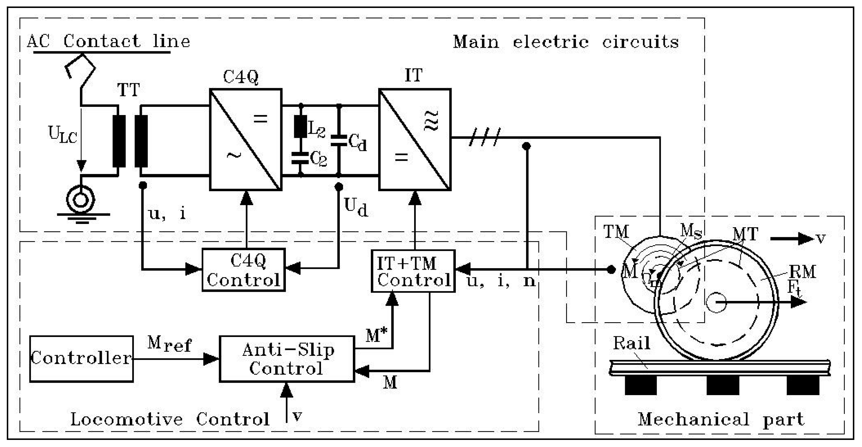
  • the main electric circuits, which include the traction transformer (TT), the contact line side-converter (of type C4Q), a resonant filter L2C2, the machine-side converter (IT) and the electromagnetic part of the traction induction motor (TM);
  • the mechanical portion, which includes the mechanical part of the traction induction motor and mechanical transmission (TM) from the electric motor to the motor wheel (RM); and
  • the locomotive control system, which includes the line-side converter control subsystem, the control subsystem of the voltage-source inverter + traction induction motor assembly (IT + TM) and the anti-slip control subsystem.
Figure 1. Electrically driven systems with traction induction motors used in modern high-speed trains fed from an a.c. contact line.
Sustainability 07 03441 g001
The main electric circuits (see Figure 1) ensure two conversion stages of the electric energy, the first being achieved by the line-side converters and the second by the machine-side converters [6,7,8,9,10,11]. In the case of an a.c. line supply, the network-side converter is a four-quadrant converter (C4Q), associated with a VVVF inverter (IT), which represents the machine-side converter (see Figure 1).
The utilization in railway electric traction of the induction motor with a squirrel-cage rotor became possible only in the conditions of supplying power with controlled variable frequency and r.m.s. voltages [2,3,9,10,11,12,13,14,15]. This power supply is based on a system of voltage and frequency static converters (loaded on the vehicle), consisting of a machine-side converter and a contact line-side converter. During railway vehicle operation, braking systems have the same importance as traction systems. The electrical brake of railway vehicles is based on the reversibility principle for electrical machines, which indicates that an electric machine can pass from the electric motor regime to the electric generator regime, only by operation control modifications. Since electric drive systems are used with contact line-side converters, machine-side converters and traction induction motors, by an appropriate control, the electric braking regime of the electric traction vehicles can be realized with the same motors.
One could note that, from an operational point of view, the presence on the vehicle of the machine-side converter is compulsory, since this equipment ensures the variable parameters of three-phase energy supply of the traction induction motor. On the other hand, the presence on the traction vehicle of a contact line converter is necessary when the parameters transformation of the electric energy supplied by the contact line is imposed. As an overview (see Figure 2), one could notice that, from this point of view, on the railway electric vehicles equipped with traction induction motors, the main electric circuits can be characterized by:
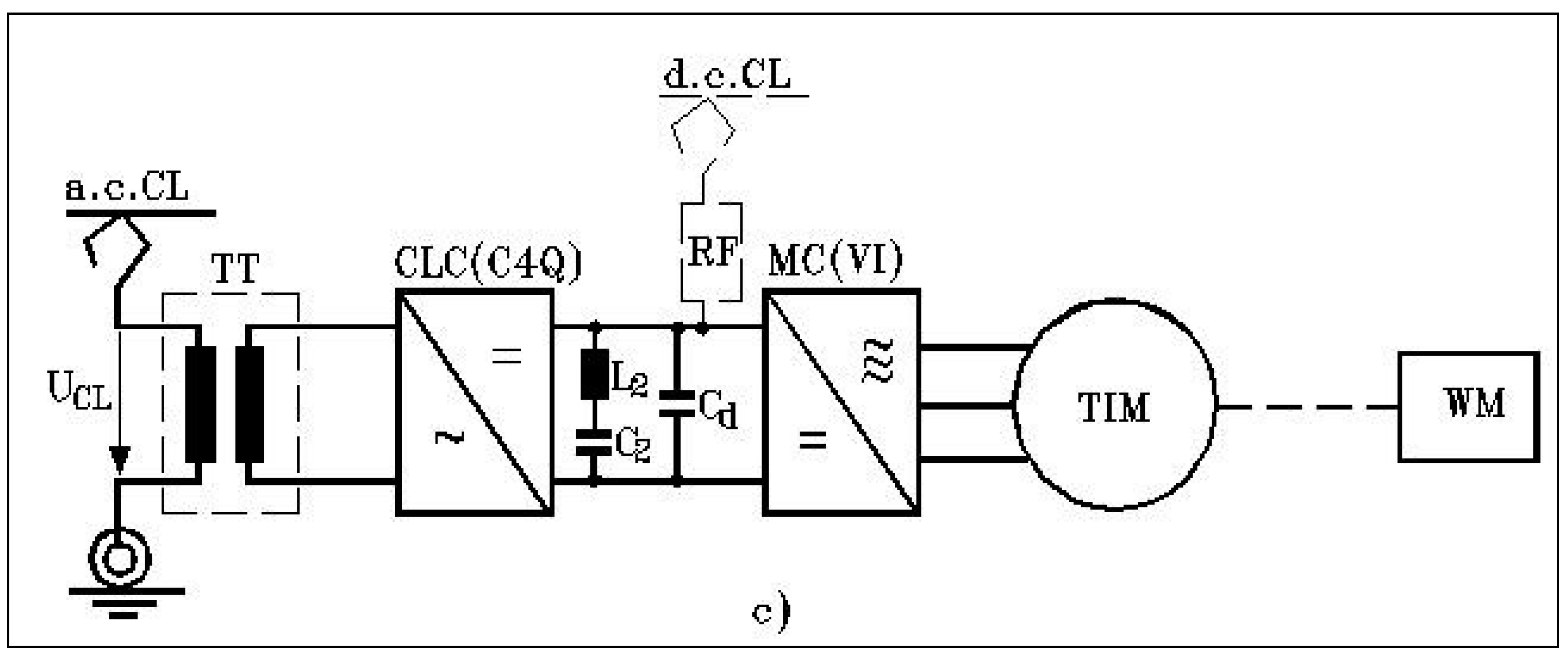
  • a single-stage energy conversion (see Figure 2a), when solely the presence of the (MC) is imposed; this situation is met in case of the vehicles supplied by a d.c. contact line;
  • a two-stage energy conversion (see Figure 2b,c), when both the contact line-side converter (CLC) and the machine-side converter MC are necessary.
The type of contact line-side converter depends on the wave form of contact line voltage, and might be:
  • a two-quadrant converter (C2Q) in the case of vehicles supplied from a d.c. contact line (Figure 2b), or
  • a four-quadrant converter (C4Q) in the case of vehicles supplied from an a.c. contact line (Figure 2c).
In this paper, the main sustainability aspects are investigated with regard to the main electric system encompassing the contact line-side converter, the machine-side converter and the traction induction motor operating at variable frequency.
Figure 2. Structure of main electric circuits on railway electric vehicles/electric trains with traction induction motors: (a) single-stage energy conversion (with supply from a d.c. contact line); (b) two stages energy conversion (with supply from a d.c. contact line); (c) two stages energy conversion (with supply from an a.c. contact line).
Sustainability 07 03441 g002aSustainability 07 03441 g002b

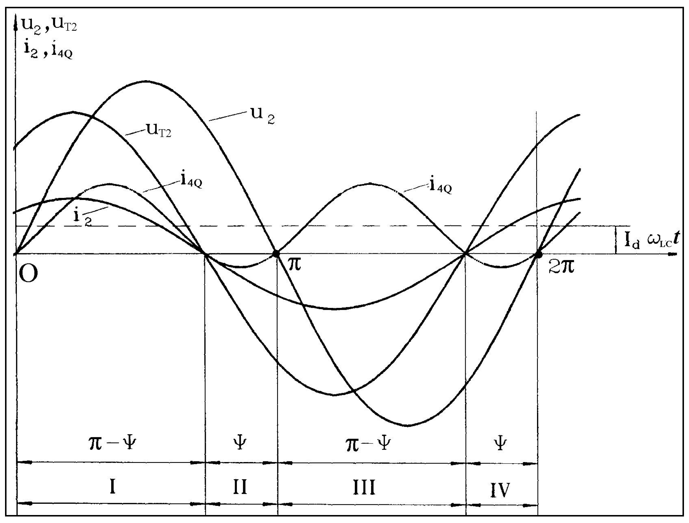
2. Sustainable Operation of a.c. Contact Line-Side Converter C4Q

As stated in the first section of this paper, in the case of electric railway vehicles (locomotives and trains) supplied from an a.c. network the sustainability requirements impose the presence of a contact line-side line converter (CLC) in the electric main circuits on the vehicle (see Figure 2c). From the operation point of view this equipment is a rectifier with birectional power flow [9,10,11].
A type of line contact-side converters that meet the sustainability requirements is the Four-Quadrant Converter (C4Q) which constitutes part of the main electric circuits on any high speed train provided with traction induction motors and supplied from a single-phase a.c. contact line. The C4Q has two tasks [9,10,11]:
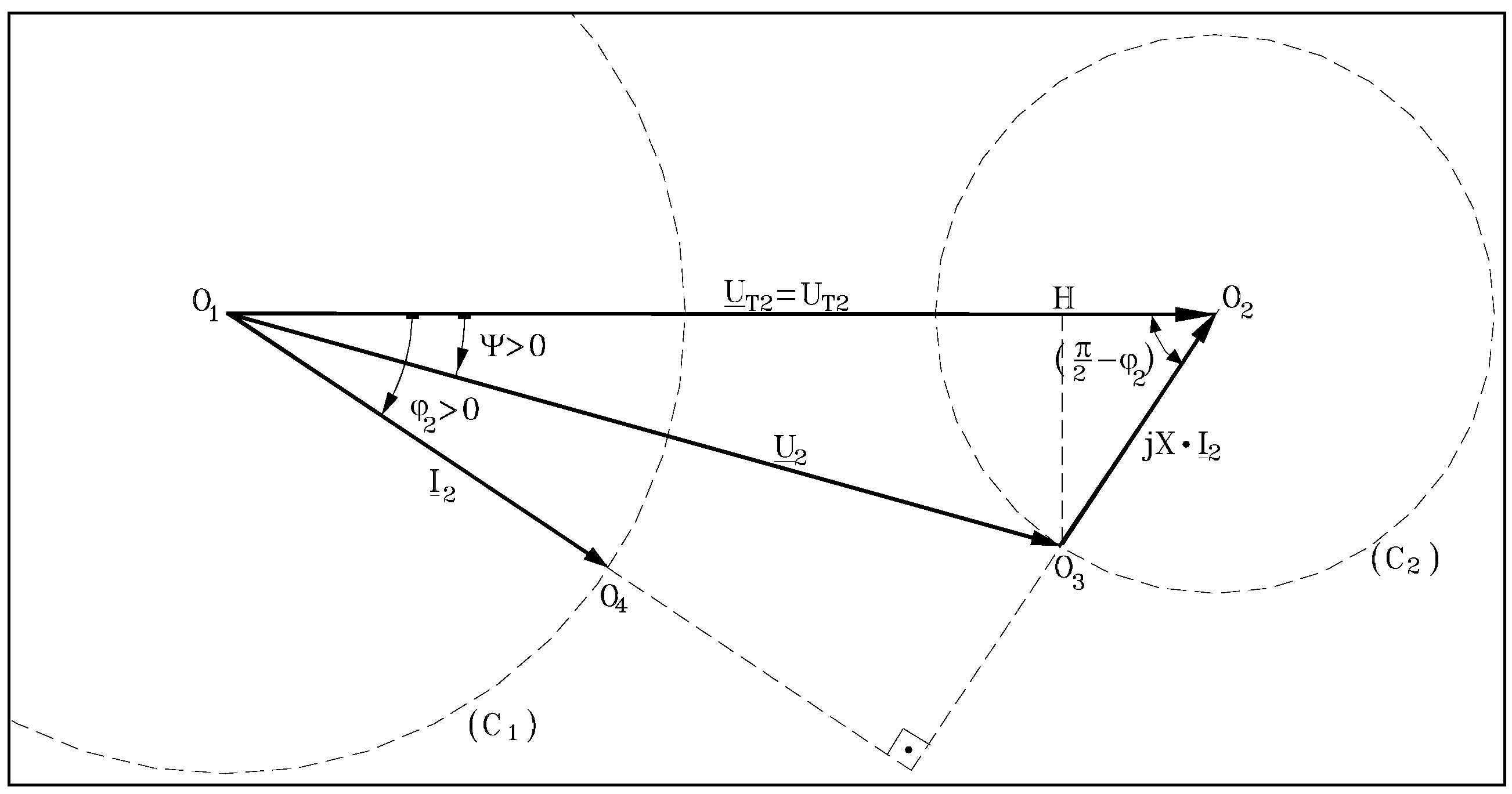
  • To absorb from/give to the contact line a current with negligible harmonics’ content (meaning nearly sinusoidal), whose fundamental must be in phase/opposite phase with the contact line voltage, ensuring a power factor cosφ ≈ 1 (in the traction regime) and cosφ ≈ −1 (in the braking regime), and
  • In traction regime, to absorb from the contact line pulsating electric power and to provide to the VVVF inverter (the machine-side converter) direct electric power (and the reverse in recuperative braking regime).
Regarding the structure of the C4Q, this type of network-side converter, in version with GTO thyristors, encompasses four pairs of TD elements (thyristors-diode antiparallel) connected in a single-phase bridge, a high value inductance L (on the a.c. side) and a series circuit L2C2 (on the d.c. side) with resonant frequency equal to twice the supply voltage frequency (f0 = 2·fLC).
In Figure 3, the principal configuration of a C4Q on an electric railway vehicle (with induction motors) supplied from an a.c. contact line is depicted. Note that C4Q is fed from the secondary of a single-phase transformer, which includes (through a proper design) the inductance L.
Figure 3. Equivalent Kapp diagram of the transformer and four-quadrant converter.
Sustainability 07 03441 g003
The operation of C4Q is briefly analyzed, taking into consideration solely the fundamentals of voltage and current on the c.a. side. Thus, considering the supply sinusoidal voltage uT2 as a reference quantity (with the r.m.s. value UT2 = ct. and the initial phase zero), both the current i2 and the voltage u2 will have a sinusoidal variation in time, but lagging with angles φ2 and ψ, respectively.
Mathematically, we can write:
    u T 2 = 2 U T 2 sin ω LC t    i 2 = 2 I 2 sin ( ω LC t φ 2 )    u 2 = 2 U 2 sin ( ω L C t ψ )
and then the equations in simplified complex as below, which allow the phasor representation in Figure 4:
U _ T 2  = j X I _ 2  +  U _ 2     I 2 = ( U _ T2 U _ 2 ) j X   X =ω L C L;   L = L k
where:
U _ T 2  =   U T 2  ;   I _ 2 =  I 2 e j φ 2 ; U _ 2 =  U 2 e j ψ
Figure 4. Phasor representation of birectional converter C4Q.
Sustainability 07 03441 g004
The phasor diagram permits the assessment of the active power P and reactive power Q exchanged by the C4Q with the supply network, which is an important sustainability aspect of the C4Q operation.
The active power P absorbed by the C4Q at the terminals “a-x” is
P = P T 2   = U T 2   I 2 cos φ 2
On the basis of mathematical calculation,
U 2 sin ψ = X I 2 sin ( π 2 φ 2 )   ⇒  I 2 cos φ 2 = U 2 sin ψ X
takes the final form:
P = P T 2 = U T 2 U 2 sin ψ X = U T 2 2 X ( U 2 U T 2 sin ψ )
The reactive power Q absorbed by C4Q at the terminals “a-x” is
Q = Q T 2 = U T 2 I 2 sin φ 2
and based on mathematical calculation,
U T 2 = U 2 cos ψ + X I 2 cos ( π 2 φ 2 )   ⇒  I 2 sin φ 2 = U T 2 U 2 cos ψ X
takes the final form:
Q = Q T 2 = U T 2 U T 2 U 2 cos ψ X = U T 2 2 X ( 1 U 2 U T 2 cos ψ )
One could note that the above relations of P and Q highlight that, in terms of given constant values of the supply voltage UT2 = ct. and of the inductance L = X/ωLC = ct., the power P and Q might be modified by controlling solely the amplitude ( 2 U 2 ) and the phase ψ of the fundamental of voltage u2 (on the a.c. side of the converter C4Q).
It must be emphasized that at I2 = constant and φ2 = variable, the two circles (C1) and (C2) in Figure 4 represent the locus of the tips O3 and O4 of the phasors I2 and U2, respectively.
With the aim of sustainable locomotives and electric trains, two operation modes of the converter C4Q are of great interest, namely:
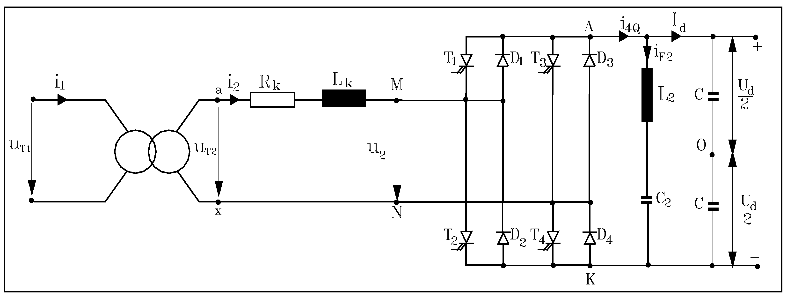
  • Operation as a rectifier with cosφ1 ≈ cosφ2 = 1 (in the traction regime), and
  • Operation as an inverter with cosφ1 ≈ cosφ2 = −1 (in the braking regime).
The phasor diagrams in these two cases (with φ2 = 0 and φ2 = π, respectively) are depicted in Figure 5. In both cases, one could write:
U 2 = U T 2 2 + ( X I 2 ) 2 U T 2 = U 2 cos ψ ; X I 2 = U 2 sin ψ tgψ =  X I 2 U T2  
Figure 5. Phasor diagrams of C4Q in rectifier mode with cosφ2 = 1 (upper) and in inverter mode with cosφ2 = −1 (bottom).
Sustainability 07 03441 g005
On the other hand, between the r.m.s. value U2 (of the supply voltage fundamental of the converter C4Q) and the value Ud (of the voltage on the d.c. side), one might postulate a proportionality relationship as follows:
   U 2 = k 4Q U d o r U 2 U d = k 4 Q
Physically, note that the bridge of C4Q does not encompass elements able to store or dissipate the electromagnetic energy. This means that the instantaneous value of the power p2 (at the input M-N in Figure 3) is equal at any time moment to the power pd (at the output A-K from the converter bridge).
Consequently, the conservation equation of the instantaneous powers is:
p 2  =p d     or    u 2 i 2 = U d i 4Q
After mathematical calculations, taking into account the expressions for u2 and i2 (with φ2 = 0), the current i4Q becomes
i 4Q  = i 2 u 2 U d = 2 I 2 sin(ω LC t) 2 U 2 sin(ω LC t ψ) U d =2 I 2 k 4Q sin(ω L C t) sin(ω L C t ψ)               I 2 k 4Q cosψ   I 2 k 4Q cos(2ω LC t ψ) =  I d + i F2
Note that the current i4Q has two components:
  • a constant component with magnitude Id, where:
    I d = I 2 k 4Q cosψ = k 4Q U T2 t g ψ X cos ψ = k 4Q U T2 X sinψ
  • an alternating component iF2 (with harmonic variation in time) by pulsation 2·ωLC and r.m.s. value IF2, where:
    I F2 = k 4Q I 2 2 = k 4Q U T2 2 X tgψ
As a physical phenomenon, the harmonic component iF2 will always be absorbed by the resonant circuit L2C2 with twice the supply voltage frequency:
f 0 = 2 f LC    or    ω 0 = LC     1 L 2 C 2 = LC
Consequently, the d.c. intermediate circuit is followed solely by the constant component Id.
From the previous relations of Id and iF2, if UT2 = ct. and X = ct., the magnitude and sense of both components of current i4Q are seen to be dependent only on the magnitude and sense of the angle ψ between u2 and uT2.
At ψ = 0, we find that Id = 0 and and IF2 = 0.
At positive phase shifts ψ > 0, Id > 0 (traction regime), while at negative phase shifts ψ < 0, Id < 0 (braking regime).
Consequently, from the sustainability point of view, note that, through the magnitude and phase control of the voltage u2, the operation regime (traction and brake, as well) of the converter C4Q may be successfully controlled.
Graphically, according to the above relations, the waveforms of voltages (uT2, u2) and currents (i2, i4Q) in the traction regime are depicted in Figure 6.
Note also that during each time period T = 1/fLC four distinct intervals of converter C4Q operation are highlighted. Thus, in the intervals I and III (with width π – ψ), the power p2 = u2·i2 is positive (on interval I, u2 > 0 and i2 > 0, while on interval III u2 < 0 and i2 < 0) and the converter is operating in a rectifier regime, with the currents flowing solely through the diodes’ branches. On the contrary, in the intervals II and IV (both with width ψ), the power p2 is negative, and the converter C4Q is operating in a single-phase inverter regime, providing reactive power towards the a.c. circuit (this power being taken from the d.c. intermediate circuit).
Figure 6. Representations of variation in time of voltages and currents of converter C4Q in traction regime (Id > 0).
Sustainability 07 03441 g006
In a similar way, we emphasize the operation of converter C4Q in recuperative braking regime (Id < 0) when the current i2 is in opposite phase with the voltage uT2 and u2 is leading uT2 with the angle ψ < 0, which determines the modification of the four operation intervals.
Note, at this point, the sustainability of the converter C4Q which, whatever is the vehicle operation regime (traction or brake), is functioning in all four quadrants of the axis system (u2, i2).

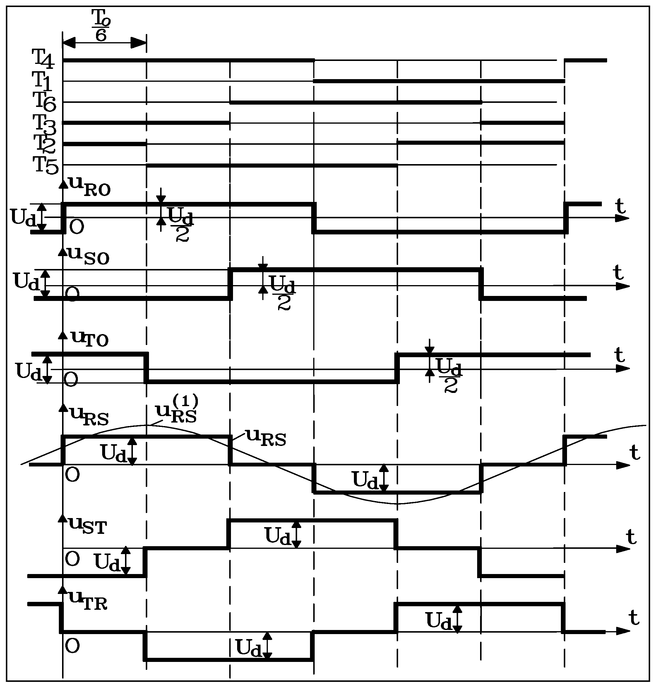
3. Machine-Side Converter of Type VVVF Inverter

Over the last decades, electric railway vehicles have utilized the machine-side converter of the voltage inverter type. Depending on vehicle power and supply characteristics, there currently are two widely utilized VVVF inverter types: with two levels and with three levels [7,8,9,10,11]. These inverters could encompass classic thyristors, GTO thyristors or IGBTs (just in case of three level voltage inverters).
The principal scheme of a voltage inverter with two levels (see Figure 7) encompasses a three-phase bridge of bidirectional elements of type T-D (with six thyristors T1...T6 in anti-parallel with six diodes D1...D6). This way, the current can flow freely in both senses through the diodes D1…D6 and in a controlled manner through the thyristors T1...T6.
Figure 7. Representation of a two-level VVVF inverter.
Sustainability 07 03441 g007
Recall that the elementary operation cycle Tc entails the time interval t' in which the phase R is connected to the positive terminal A (when T4 is in conduction) and the time interval t" in which the phase R is connected to the negative terminal K (when T1 is in conduction):
T c = t + t
Depending on the mathematical relation between To and Tc, two operation types of the voltage inverter have been obtained with two levels utilized for supplying traction induction motors:
  • if Tc = T0, the inverter will operate in full wave (rectangular form);
  • if Tc < T0, the inverter will operate in width modulation regime of voltage pulses.
In this paper, we illustrate as an example the inverter operation with a full wave.
This regime corresponds to an induction motor supplied at over-rated frequencies (ωs > ωN), when the supply voltage of the traction motor is maintained constant (Us = UN). Under the conditions t' + t" = Tc and Tc = T0, the time intervals t' and t" will be equal, with the magnitude:
t = t = T c 2 = T 0 2
The voltage uRO takes on the value uRO = Ud/2 during the conduction of T4 and uRO = −Ud/2 during the conduction of T1. The voltages uSO and uTO will have the same values, but delayed in time by T0/3 and 2T0/3, respectively, corresponding to the conduction of T6 and T3, and to the conduction of T2 and T5, respectively. Taking into consideration the relations among the simple voltages uR0, uS0, uR0, uN0 and the composed voltages uRS, uRN, uST, uSN, uTR, uTN:
u RS = u RO u SO ; u ST = u SO u TO ; u TR = u TO u RO u RN = u RO u NO ; u SN = u SO u NO ; u TN = u TO u NO
the waveforms corresponding to this operation regime of the voltage inverter with two levels is obtained, as depicted in Figure 8.
Figure 8. Waveforms corresponding to variable voltage variable frequency (VVVF) inverter with two levels of operation in full wave.
Sustainability 07 03441 g008

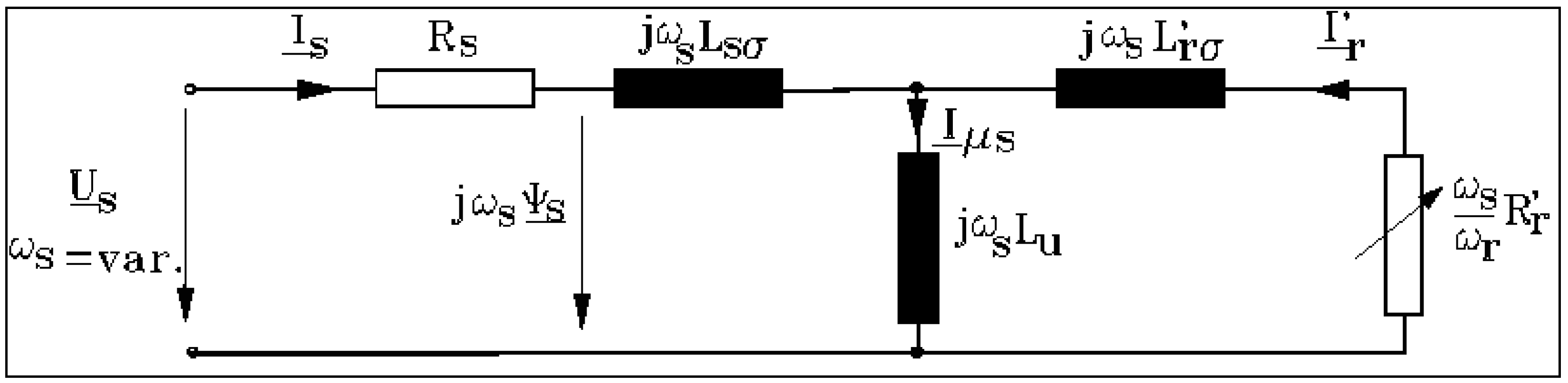
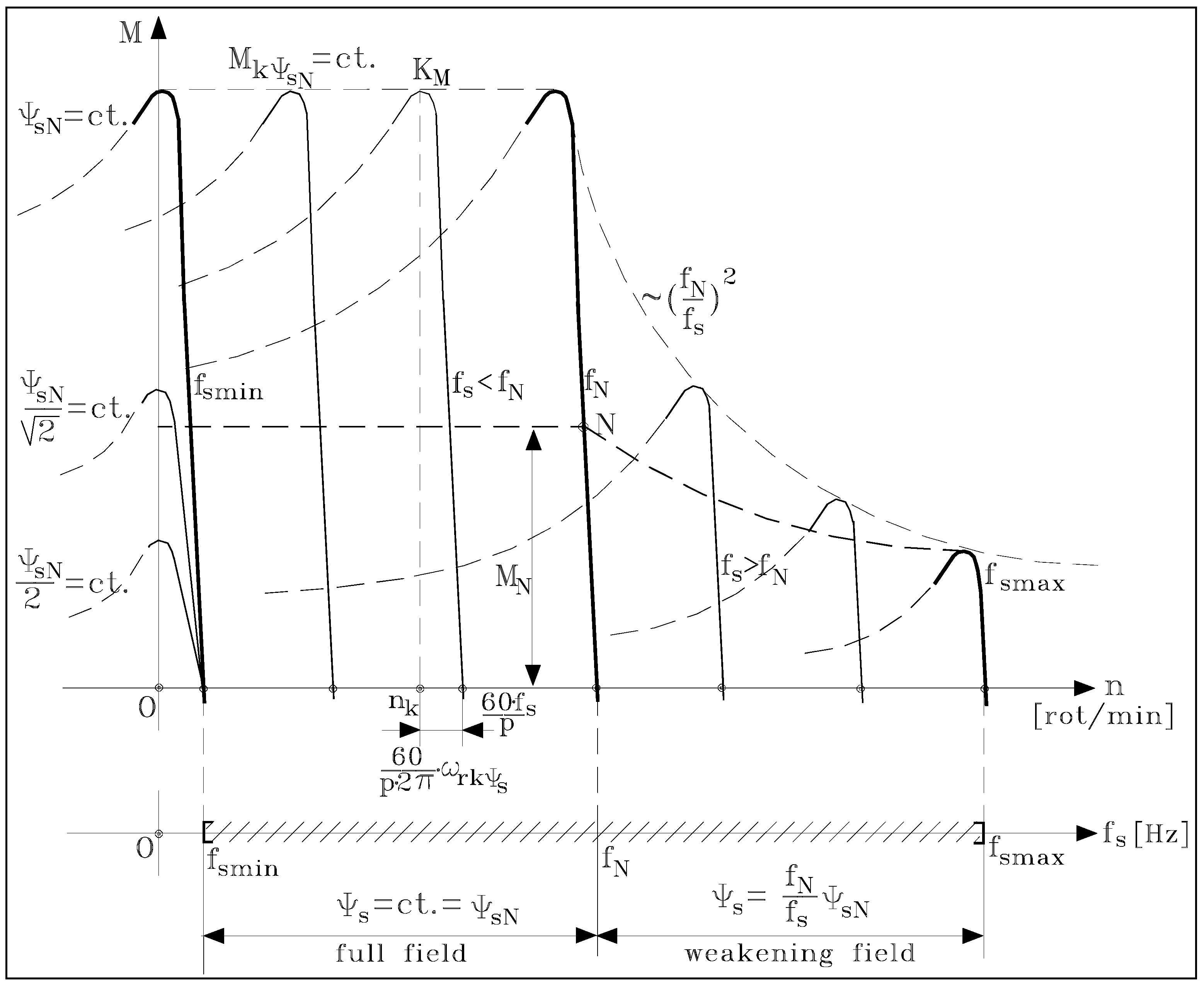
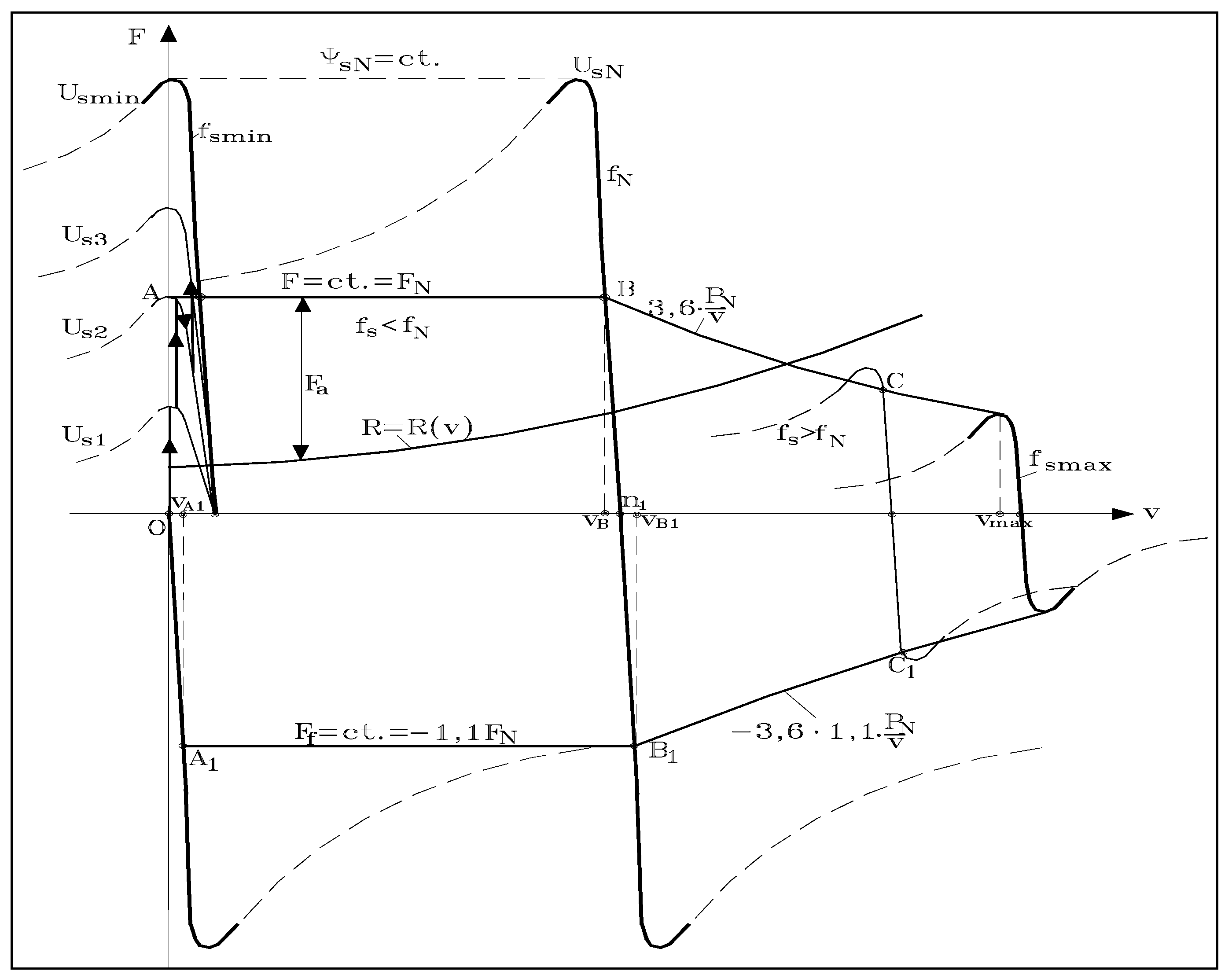
4. Sustainable Operation of Traction Induction Machine at Variable Frequency

Electric railway trains supplied by an a.c. or a d.c. contact line are equipped with three-phase induction motors and variable voltage and frequency inverters [2,3,7,8,9,12,13,14,15]. Since electric drive systems are used with VVVF inverters and traction induction motors, with appropriate controls these machines can realize both traction and electric braking regimes of electric traction vehicles.
In electric traction, the requirements for the induction motor are [6,7,8,9]:
  • high torque at low speed, including at the vehicle starting regime; and
  • sustainable operation in a large range of supply frequency variation, from roughly 1–3 Hz up to 140–180 Hz, both in motor regime and in electric brake regime (as a generator).
The vehicle regulation speed is determined by examining the VVVF inverter and electric machine as an assembly [12,13,14,15]. We have pointed out in previous studies [2,3,14,15] that a traction electric vehicle might be analyzed as an ecosystem, and the dynamic regimes in electric train operation, e.g., starting or braking processes, can be viewed as representing the industrial ecosystem movement among points of equilibrium. Since the traction motor speed regulation is based on stator voltage and frequency variation, in order to achieve high energy and exergy efficiencies, the first requirement of the train control system concerns passing of the motor operation equilibrium point from one mechanical characteristic to another.
From a physical point of view, for any constant stator frequency 0 < fs ≤ fsmax (and any constant stator pulsation, respectively, ωs = 2πfs) the equivalent electric configuration (on a phase) of the traction induction motor is depicted in Figure 9.
Figure 9. Electric circuit of induction machine (on a phase).
Sustainability 07 03441 g009
If we note s = n s n n s   = ω r ω s =   f r f s the slip of rotor (having speed n) in the rotating magnetic field (which has the synchronism speed ns = 60·fs/p), then the electromagnetic torque M developed by the traction induction motor at any current value of the stator frequency fs and rotor slip s (respectively, rotor pulsation ωr = s·ωs) is specified by:
M =  3p ω s R r s I r  2 = 3p R r ω r I r  2
Note that neglecting the stator resistance (Rs ≈ 0), the evaluation relation of the electromagnetic torque M of the traction induction motor at variable frequency is considerably simplified, as follows:
M = M ( ω s , ω r ) = 3p 1 σ σ L s ( U s ω s ) 2 R r ω r σ L r + ω r σ L r R r
with the notation ω m = p Ω m   = p 2 π n 60 , the torque characteristic of the induction motor, meaning the curve M = f(ωm) for any constant pulsation/frequency ωs = 2πfs = ct. and ωm = ωs − ωr is graphically illustrated in Figure 10.
The specific points of the mechanical characteristic in Figure 10 have the coordinates (for any constant value of the stator frequency fs) given by:
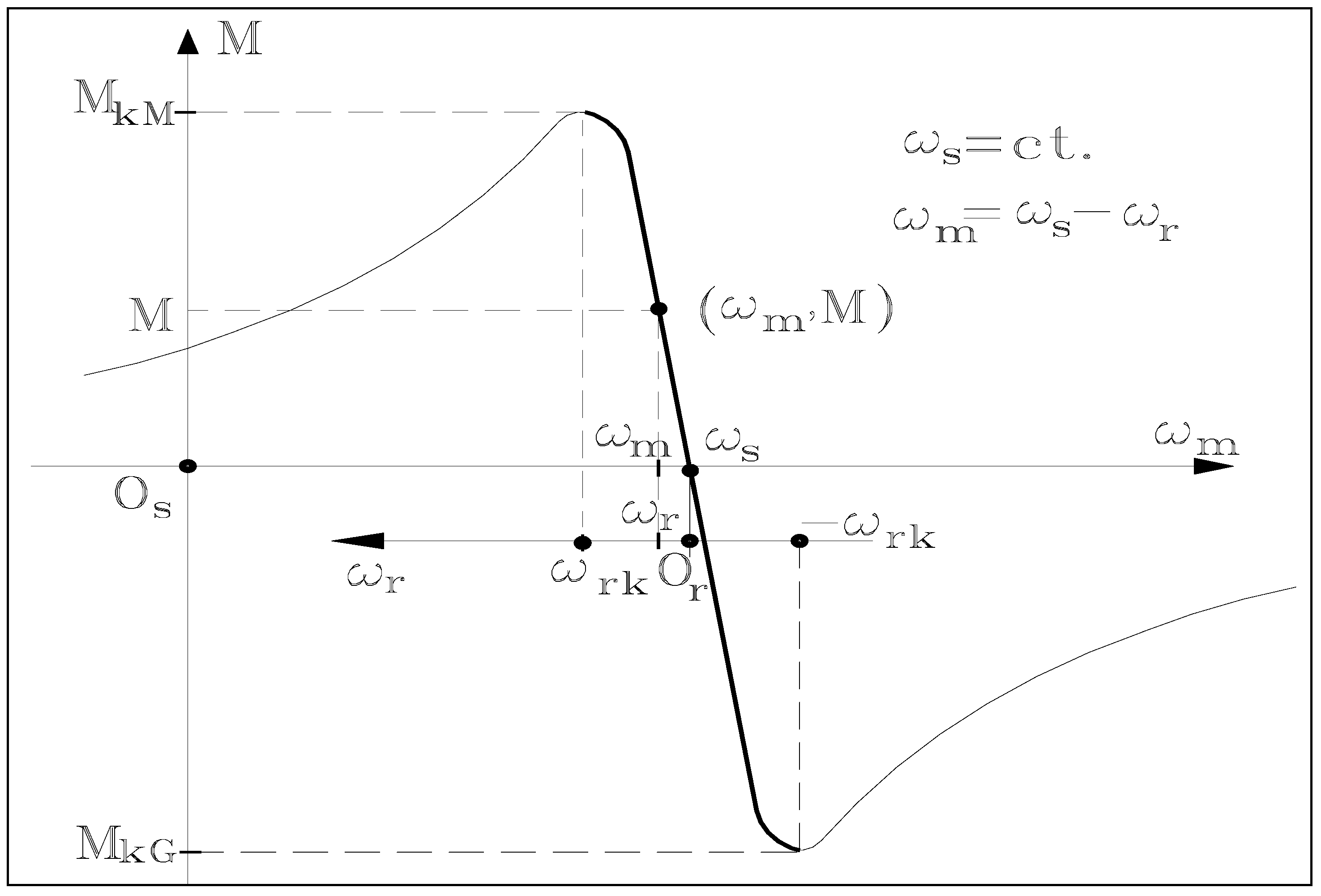
  • mechanical pulsation ωm corresponding to the synchronism point (intersection with abscissa axis):
    ω m = ω s = 2 π f s   = 2 π p n s 60
  • critical rotor pulsations ωrk (extreme points’ abscissa of the graph in Figure 10):
    ω rk   = ω rk ψ s =   ± R r σ L r
  • extreme values (critical as motor MkM and generator MkG, respectively) of the torque curve:
    M k = M k ψ s   =   ± 3p 2 1 σ σ L s ( U s ω s ) 2
Note in the above relation that the sign “+” refers to motor regime (with index M in Figure 10) while the sign “−” refers to generator regime (with index G in Figure 10).
Figure 10. Mechanical characteristic M = f(ωm) at ωs = ct. (or fs = ct.).
Sustainability 07 03441 g010

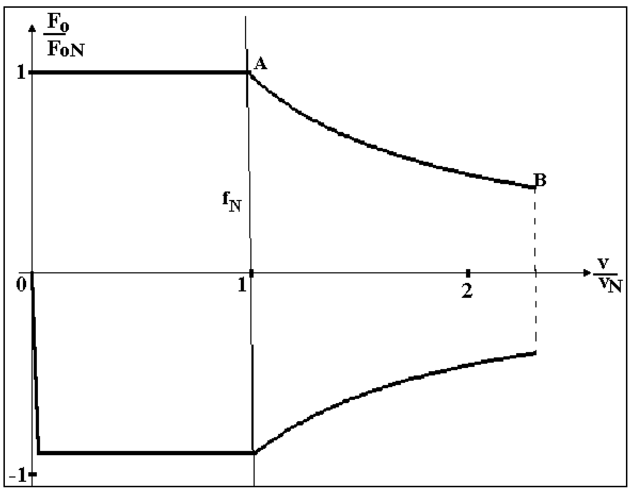
Assessment of Variation Range of Stator Frequency

At the supply with variable frequency voltages (or currents), it is important to assess the limit values of stator minimum frequency fsmin and maximum frequency fsmax (as in Figure 11, in the bottom part) among which the stable operation of the traction induction machine is possible [15].
The minimum frequency (at operation with constant stator flux, see Figure 11) is assessed taking into consideration that in a steady-state regime, at any value of stator frequency fs, among rotor pulsation ωr, stator pulsation ωs = 2π·fs and mechanical pulsation ωm = p·Ωm = p·2π·n/60, the relation is valid (Frequency Theorem):
ω s = ω m + ω r
Note further that during the traction induction motor operation, for any value of the stator frequency fs and rotor pulsation ωr, in a steady-state regime the magnitude of rotor speed n will result in:
f s  = p n 60  +  ω r           n =  60 p ( f s   1 ω r )
Since the induction motor operation (at the stator frequency fs) is performed at constant stator flux ψs = ψsN = ct., then the rotor speed nk corresponding to maximum electromagnetic M (meaning the abscissa of point KM in Figure 11) will be established with the relation:
n k = 60 p ( f s     1 ω rk ψ s ) ;     n k    0
The minimum stator frequency fsmin (that still will ensure the above operation conditions) corresponds to the limit situation when nk = 0. The minimum stator frequency will be given by the relation:
f s m i n = 1 2 π ω r k ψ s = 1 2 π R r σ L r
This is the minimum value of stator frequency that must be ensured by the supply source. Note that fsmin depends solely on the parameters R'r, L'r and σ of the traction induction machine.
Figure 11. Overview of traction induction motor characteristics in operation at variable stator frequency fs.
Sustainability 07 03441 g011
In Figure 11, the smooth starting manner (without shocks) is highlighted, through a progressive increase of the stator flux ψs (from 0 up to ψsN) at the minimum value fsmin = ct. (of the supply stator frequency), followed by an increase of the stator frequency fs (at the constant stator flux a ψs = ψsN = ct.) simultaneously with the increase of rotor speed.
The maximum frequency is addressed subsequently. The maximum frequency f smax is established by the condition of development (still) of an electromagnetic power PM of magnitude equal to that of the motor rated operation.
In the case considered subsequently of an induction machine supplied by a variable frequency voltage source, when the rated speed is reached (i.e., the induction motor is supplied at UN and fN) a further increase in speed is possible only by increasing the stator frequency magnitude over the rated frequency fs > fN. Note that because of the voltage restriction on both supply inverter and induction machine winding insulation considerations, the stator voltage is limited and maintained at a constant magnitude Us = UN for the entire high frequency domain, and the induction machine operates in weakened flux conditions [9,15]. Because the stator flux and pulsation exhibit an inverse proportionality relation Ψs = UNs, the machine torque capability is strongly affected (see Figure 12). This is the reason for the limited increase of stator frequency.
Figure 12. Mechanical characteristics at Us = UN = ct. and different stator frequencies fs > fN.
Sustainability 07 03441 g012
Usually, the decrease of the stator flux ψs is performed on the basis of the law “1/ωs”, meaning:
ψ s = ψ s N ω N ω s U N ω s
Simultaneously, with the decrease of flux ψs, a reduction of the maximum electromagnetic torque occurs, and its expression at over-rated frequencies fs > fN becomes:
M k ψ s = 3p 2 1 σ σ L s [ ψ sN ω N ω s ] 2 = M k ψ sN ( ω N ω s ) 2
Accordingly, in the range of over-rated frequencies (fs > fN) the electromagnetic torque M (for ωr = ct.) is decreasing at the same ratio. These findings are graphically illustrated in Figure 11 (in the right side, in the high speed domain) by three mechanical characteristics M = f(n) at weakened flux according to the law Ψs = ΨsN·ωNs and fs = ct. (with fs > fN).
In this context, the maximum value of the stator frequency fsmax is established from the electromagnetic power invariance condition PM = M·Ωs = M·ωs/p (transferred by air-gap) at different over-rated values of stator frequency fs.
In order to keep a constant electromagnetic power (PMN = ct.) between the rated stator frequency fN and the maximum stator frequency fsmax, the following relation should be met:
M N ω N p = M f s m a x ω s m a x p
If at the maximum frequency fsmax the condition M f s m a x = M k ψ s is imposed, the following results:
M N ω N p = M k ψ s N ( ω N ω s m a x ) 2 ω s m a x p ω s m a x = M k ψ s N M N ω N
or taking into account the definition of the torque overload capacity λM we obtain:
λ M = M k ψ s N M N f s m a x = λ M f N
Consequently, the increase of the maximum frequency fsmax can be achieved through the design and further construction of induction machines with increased torque overload capacity λM. For traction induction machines, λM can take on values of 2.5–3.0.
For example, in Figure 13 we illustrate (reported to the rim) the mechanical characteristics for distinct stator frequencies and the traction/brake characteristics of a traction induction motor operating at frequency varying in the range fsmin at the starting regime and fsmax corresponding to maximum speed vmax.
Figure 13. Starting and mechanical characteristics for different stator frequencies and building of traction/brake characteristics of traction induction motor12.
Sustainability 07 03441 g013
Note that the induction machine supplied from a variable frequency and voltage inverter operates with full field ψs = ψSN = ct. in the low frequency range fs≤ fN and with a weakened field (ψsSN) in the increased frequency domain fs > fN (when the supply r.m.s. voltage remains constant Us = UN = ct.), as highlighted in Figure 13. The maximum variation range of the stator frequency is limited by f smin and f smax , where f smin = 1 2 π R r σ L r and f smax = λ M f N ;. The minimum frequency f smin is limited by the condition of a smooth starting of the motor, without shocks, only by continuing increase of the stator flux of 0 to ψSN (even from n = 0), thereby ensuring stable operation (on the bold zone of the mechanical characteristic).
Further reporting to rim has been performed in this paper on the basis of the following relations:
v Ω m = D r 2 i ;      F o η t M = 2 i D r
where v denotes the vehicle speed; Ωm the mechanical angular speed; Dr the running diameter; i the transmission ratio; ηt the mechanical transmission efficiency; F0 the traction/brake force and M the electromagnetic torque.
In Figure 14, we represent separately the traction and brake characteristics of electric railway vehicles with traction induction motors (taken from Figure 13), with the driving wheels having the running diameter Dr, and with a mechanical transmission having an efficiency ηt and a transmission ratio i.
Figure 14. Traction and brake characteristics of the electric railway vehicle with traction induction motors.
Sustainability 07 03441 g014

5. Conclusions

The operation sustainability of electric railway vehicles has been addressed, highlighting the chain of interactions within the main electric equipment on an electrically driven railway system supplied from an a.c. contact line: the contact line-side converter, the machine-side converter and the traction induction motor. The paper supports the findings that electric traction drive systems using induction motors fed by variable voltage variable frequency (VVVF) inverters enhance the sustainable operation of railway trains.
Electric traction drive systems using induction motors fed by VVVF inverters provide high performance for urban electric trains, in terms of both train dynamics and environmental issues, while advanced power VVVF inverters and efficient anti-slip systems ensure optimum traction and minimum energy use.
Regarding train electric braking, actual techniques have been pointed out that allow driving systems to be implemented on the basis of the VVVF inverters and induction motors, which facilitate improved electric braking, even with energy recovery. In that operating regime, the vehicle provides energy to the d.c. network through the machine-side converter and the contact line-side converter. The environmental impacts of electric braking are considerably reduced by converting traction machines to an electric generator regime, particularly when energy recovery is applied. In that operating regime, the vehicle provides energy to the network through the inverter.
The physical phenomena within the electric system composed by the contact line-side converter, the machine-side converter and the traction induction motor are complex, and its overall behaviour suggests that industrial ecology offers an appropriate framework for assessing the sustainability of industrial ecosystems as an electric railway system.

Author Contributions

Marc A. Rosen and Doru A. Nicola designed the research. Also, Marc A. Rosen carried out the analysis of the sustainable operation of the machine-side converter of type VVVF inverter, and Doru A. Nicola developed the mathematical model of a.c. contact line-side converter C4Q. Cornelia A. Bulucea carried out the analysis of the operation of induction motor at variable frequency and drafted the manuscript. Daniel C. Cismaru performed the holistic analysis of electrically driven systems with traction induction motors used in modern high-speed trains fed from an a.c. contact line and of the structure of main electric circuits on railway electric vehicles/electric trains with traction induction motors. All authors read, enhanced and approved the final manuscript.

Nomenclature

f s , f N
stator frequency (rated stator frequency) [Hz]
i
transmission ratio of gear reducer
i d 2
input current of VVVF inverter [A]
i R , i S , i T
output currents of VVVF inverter [A]
n
rotor speed [rpm]
ns
synchronous speed [rpm]
p
poles pair number of induction motor
C2Q
two-quadrants converter
C4Q
four-quadrants converter
Dr
wheel diameter [m]
F
total traction force [N]
F 0
active motor force at rim [kN]
FF
braking force at rim [kN]
IT (VI)
two levels VVVF inverter
FR (RF)
input filter (network filter)
L s , L r , L u
stator, rotor and useful (magnetizing)cyclical inductances [H]
M ( M k , M N )
electromagnetic torque (maximum electromagnetic torque, rated electromagnetic torque) [Nm]
TIM
traction induction motor
P 0
active power at rim [kW]
R s
phase stator winding resistance [Ω]
R r
rotor resistance reduced to stator [Ω]
U 1 , I 1
supply line voltage and RMS current of induction motor [V], [A]
Ud
input voltage of VVVF inverter [V]
U s ( U N )
RMS phase stator voltage (RMS rated stator voltage) [V]
VVVF
Variable voltage variable frequency
ηt
transmission efficiency of gear reducer
ωm = 2πpn/60
mechanical angular frequency [elect.rad/s]
ωr = ωs − ωm
rotor angular frequency [elect.rad/s]
ωs = 2π fs
stator angular frequency [elect.rad/s]
ωN
rated stator angular frequency [elect.rad/s]
σ
leakage coefficient of induction machine (Blondel coefficient)
m
mechanical angular speed of traction motor rotor [rad/s]
Ψs (ΨsN)
stator total flux (rated stator total flux) [Wb.turn]

Conflicts of Interest

The authors declare no conflict of interest.

References

  1. Rosen, M.A.; Bulucea, C.A. Using exergy to understand and improve the efficiency of electrical power technologies. Entropy 2009, 11, 820–835. [Google Scholar] [CrossRef]
  2. Nicola, D.A.; Rosen, M.A.; Bulucea, C.A.; Brandusa, C. Sustainable energy conversion in electrically driven transportation systems. In Proceedings of the 6th WSEAS International Conference on Engineering Education (EE’09), Rhodes, Greece, 22–24 July 2009; pp. 124–132.
  3. Nicola, D.A.; Rosen, M.A.; Bulucea, C.A.; Brandusa, C. Some sustainability aspects of energy conversion in urban electric trains. Sustainability 2010, 2, 1389–1407. [Google Scholar] [CrossRef]
  4. Rosen, M.A. A concise review of energy-based economic methods. In Proceedings of the 3rd IASME/WSEAS International Conference on Energy & Environment, Cambridge, UK, 23–25 February 2008; pp. 136–142.
  5. Dincer, I.; Rosen, M.A. Exergy: Energy, Environment and Sustainable Development, 2nd ed.; Elsevier: Oxford, UK, 2013. [Google Scholar]
  6. Kaller, R.; Allenbach, J.M. Traction Electrique (Electrical Traction); PPUR: Lausanne, Switzerland, 1995; Volume 1–2. [Google Scholar]
  7. Perticaroli, F. Sistemi Elettrici per i Transporti: Trazione Elettrica; Masson: Milano-Parigi-Barcellona, Spain, 1994. [Google Scholar]
  8. Nicola, D.A.; Cismaru, D.C. Tractiune Electrica: Fenomene, Modele, Solutii (Electric Traction: Phenomena, Models, Solutions); SITECH Publishing House: Craiova, Romania, 2006. [Google Scholar]
  9. Nicola, D.A. Tractiune Electrica (Electric Traction); Universitaria Publishing House: Craiova, Romania, 2012. [Google Scholar]
  10. Buhler, H. Reglage de Systemes d’Electronique de Puissance; PPUR: Lausanne, Switzerland, 1997; Volume 1. [Google Scholar]
  11. Carpita, M.; Monti, A. Voltage source converters and drives simulation at system level for control design applications. EPE J. 1996, 5, 49–55. [Google Scholar]
  12. Bulucea, C.A.; Nicola, D.A.; Brandusa, A.; Brandusa, C. Drive systems in underground metro saving energy. In Proceedings of the 3rd IASME/WSEAS International Conference on Energy & Environment, Cambridge, UK, 23–25 February 2008; pp. 433–439.
  13. Nicola, D.A.; Bulucea, C.A.; Cismaru, D.C.; Brandusa, C. Energy saving in electric trains with traction induction motors. In Proceedings of the 4th IASME/WSEAS International Conference on Energy & Environment, Cambridge, UK, 24–26 February 2009; pp. 226–232.
  14. Bulucea, C.A.; Nicola, D.A.; Mastorakis, N.E.; Rosen, M.A. Understanding electric industrial ecosystems through exergy. In Recent Researches in Energy and Environment, Proceedings of the 6th IASME/WSEAS International Conference on Energy and Environment, Cambridge, UK, 20–25 February 2011; pp. 182–191.
  15. Nicola, D.A.; Rosen, M.A.; Bulucea, C.A.; Cismaru, D.C. Some aspects of sustainable energy conversion in electric railway vehicles with traction induction motors. In Recent Advances in Systems Science, Proceedings of the 17th International Conference on Systems, Rhodes Island, Greece, 16–19 July 2013; pp. 44–53.

