1. Introduction
Cogeneration system is considered one of the most important methods for energy saving. Cogeneration systems are used where both electricity and heat are required. Cogeneration systems utilize the waste heat produced during electricity generation and apply it for heating purposes. Since cogeneration, or combined heat and power (CHP), systems produce both thermal energy (generally in the form of steam or hot water) and electricity, the first law efficiency can be increased from around 35% to 55% in conventional power plants to over 90% in CHP systems [
1,
2,
3]. Reciprocating CHP units are generally applicable in low and medium power cogeneration units. The sizes of reciprocating CHP units depend on fuel type and use. These can range from 50 kW to 10 MW for natural gas, from 50 kW to 50 MW for diesel, and from 2.5 MW to 50 MW for heavy fuel oil [
1,
2,
3]. In compression ignition (IC) engines, four methods to utilize waste heat exist: exhaust gas, engine jacket cooling water, lube oil cooling water, and turbocharger cooling water. The exhaust gases from diesel cogeneration plants are a main source of thermal energy for combined heat and power applications. The high temperature exhaust gas can produce medium pressure steam (approximately 10 Bar), low-pressure steam (approximately 2 bar) and hot water [
1,
2,
3]. Low pressure steam produced by IC engine cogeneration systems is appropriate for low temperature process needs such as space heating, potable water heating and space cooling with absorption chillers [
1,
2,
3]. Numerous energy, exergy and exergo-economic analyses of CHP or simple internal combustion engines have been reported.
Alkidas [
4] performed first and second law analyses for a diesel engine operating at constant speed. He concluded that the engine second-law efficiency increases with engine load and varies from 22 to 50 percent; he also found that the combustion process is the most important source of irreversibility and accounts for 25 to 43 percent of the lost power.
Danov and Gupta [
5] developed a model to investigate a cycle consisting of a turbocharged diesel engine (the topping cycle), a heat recovery steam generator (HRSG) and a steam turbine plant (the bottoming cycle). This model can predict cycle performance for various conditions.
Kanogluetal [
6] performed exergy and energy analyses of a 120MW diesel engine power plant. The energy and exergy efficiencies of this plant are 47% and 44%, respectively.
Ballietal [
7,
8] performed thermodynamic and thermo economic analyses of a tri generation system with a gas–diesel engine having a rated output of 6.5 MW, where the gas–diesel engine is installed in the Eskisehir Industry Estate Zone, Turkey. They calculated the efficiencies based on energy 59%), exergy (36%), public utility regulatory policies act (PURPA) and equivalent electrical of the entire system (49%).
Fu
et al. [
9] improved IC engine utilization efficiency by open steam power cycle. The bottom cycle was a four-cylinder naturally aspirated IC engine: with three cylinders taken as ignition cylinder, the last one was used for steam expansion cylinder; IC engine exhaust pipe was coupled with a Rankine steam cycle system which used the high temperature exhaust gas to generate steam. They showed that the recovery efficiency of exhaust gas energy was mainly limited by exhaust gas temperature. The maximum bottom cycle power reached 19.2 kW and IC engine thermal efficiency can be improved by 6.3% at 6000 r/min.
Ehyaei
et al. [
10] did technical, economical, and environmental study of applying internal combustion (IC) engines for supplying the required electricity, domestic hot water (DHW), heating and cooling energy loads in a typical residential building located in Tehran. They showed five units of G3306B IC engine and combined heat and power (CHP) internal combustion engine met the required energy of this building. The annual average electricity cost of this system is equal to 0.05 (US$/kWh) and the annual entropy generation of this system is equal to 29,903 (GJ/year).
Roque Díaz
et al. [
11] did a research about the Equipment selection and operation require the characterization of power, heating and cooling load demands, and their time variation during years, seasons, months and even hours or minutes.
The present research involves exergy, economic and environmental analyses of simple and CHP internal combustion engines with consideration of entropy production, second law efficiency, and energy costs, including the external cost of the environmental pollutants, such as CO
2, CO and NO, present in the flue gas of IC engines. The environmental aspects of air pollution and also other pollution impacts such as degradation of water, soil,
etc., caused by power generation systems are not included in this study. The following steps describe the scope of this study:
- (1)
Exergy and economic analyses of CHP and simple IC units are conducted.
- (2)
A computer program code is developed in FORTRAN to simulate an IC engine unit and to assess the effects of heat recovery exchangers on exergy and economic analyses.
- (3)
An economic analysis is performed, including the external cost of air pollution.
- (4)
The effects of including heat recovery heat exchangers are assessed on the cost of electricity, entropy generation and second law efficiency.
2. System Modeling
An E2876E302 IC engine with a nominal electrical power 130 kW at ISO conditions is considered. This engine uses natural gas as fuel [
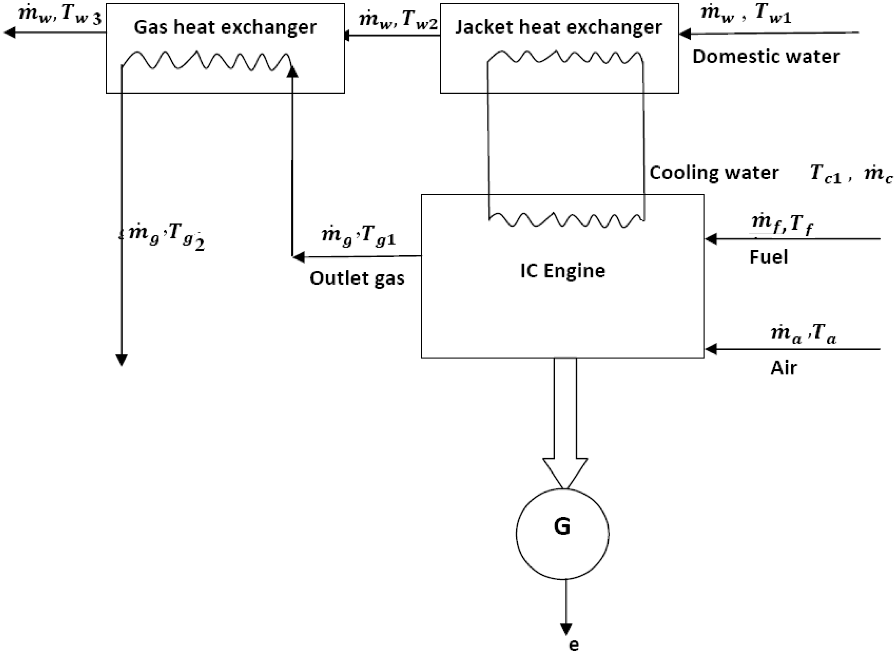
12]. The gas engine and generator are coupled by an elastic coupling, and the system is equipped with a vibration absorber, gas filter, solenoid valve pressure, fuel valve with electronic governor and electronic ignition system. In this engine, water is used for cooling purposes. Cooling water is pumped in a closed circuit by an electrical water pump. This engine is equipped with heat exchangers for the water jacket and exhaust gas for the purpose of heat recovery. In the simple IC engine mode the electrical generator is employed, while in the CHP mode the water jacket and exhaust gas heat exchangers are used. In the CHP mode and for domestic use, urban water absorbed heat from warmed cooling water in the water jacket heat exchanger passes to the exhaust gas heat exchanger where it absorbs heat from the hot exhaust gas. With water mass flow rates in both heat exchangers we calculate the temperatures of hot water for domestic consumption to be around 40–50 °C.
Figure 1 shows the configuration of this system. The specifications of the IC engine, jacket water and exhaust gas heat exchangers are provided in
Table 1,
Table 2 and
Table 3, respectively.
Energy modeling Equation is as following:
where, δQ is a heat transfer between in cylinder gases and walls (kJ). δW is a work transfer between system and environment and it is calculated from PdV Equation (kJ). The last term is related to system energy transmission with internal or external fluid mass flux (kJ).
Engine heat transfer can be calculated from Equation (2). For having more accurate engine performance estimation an empirical constant of C is used at Equation (2) that is variable by kinds of engine and fuel [
13]:
where C is constant, h is heat convection coefficient (kW/kg K), T is temperature (K), A is area (m
2) and subscript w denotes the wall.
For compression, expansion and combustion processes, following Equation can be applied:
n is number of moles, R is universal gas constant (kJ/kg K), V is volume (m3).
Noticeable point is that Equation (4) for expansion process is valid by neglecting total mole number variation during this process.
It is noticeable that at each computational step some of the unburned mixture is combusted and enters the burned zone. Therefore fluid flux exists between burned and unburned zones. Significations of this transmission are and in Equations (6) and (7). These two terms are related via mass conservation law by equation . Equation (8) can be used for calculating , which is derived based on turbulent flame speed.
Af is a frontal flame area, that it is calculated with assumption of spherical flame advance. It is modeled based on flame clash with piston wall and cylinder wall. ut is calculated with empirical relations for laminar flame velocity.
Figure 1.
Configuration of the system.
Figure 1.
Configuration of the system.
Table 1.
Specifications of the IC (internal combustion) engine.
Table 1.
Specifications of the IC (internal combustion) engine.
| Engine Specification | Value |
|---|
| Engine type | E2876E302 |
| Cylinder number | In-line 4, 4-stroke cycle |
| Cylinder bore | 128 mm |
| Motor length | 2650 mm |
| Motor width | 1000 mm |
| Motor height | 1500 mm |
| Stroke | 166 mm |
| Firing order | 1-3-4-2 |
| Speed | 1000 rpm |
| Compression ratio | 12:1 |
| Maximum electrical power at ISO condition | 130 kW |
| Weight | 1850 kg |
| Molar air-fuel ratio | 1.5 |
| Intake type | Naturally aspirated |
| Rated voltage | 220 V |
| Rated current | 18 A |
| Starting mode | 24VDC electric starting system |
| Frequency | 50 HZ/60 HZ |
Table 2.
Specifications of the jacket water heat exchanger.
Table 2.
Specifications of the jacket water heat exchanger.
| Heat exchanger specification | Value |
|---|
| Length | 1.7 m |
| Height | 1.7 m |
| Width | 1.7 m |
| Number of tubes | 30 |
| Diameter of tubes | 0.1 m |
| Length pitch | 0.15 m |
| Width pitch | 0.15 m |
| Gas mass flow rate | 2.2 kg/s |
Table 3.
Specifications of the exhaust gas heat exchanger.
Table 3.
Specifications of the exhaust gas heat exchanger.
| Heat exchanger specification | Value |
|---|
| Length | 1.5 m |
| Height | 1.5 m |
| Width | 1.5 m |
| Number of tubes | 31 |
| Diameter of tubes | 0.1 m |
| Length pitch | 0.125 m |
| Width pitch | 0.125 m |
| Mass flow of cooling water | 7 kg/s |
Power to heat ratio is a key parameter and can be calculated as follows [
14]:
Here,
is the net electrical power (W), and
is the net heat recovered in water jacket and gas heat exchangers (W). The first law (or energy) efficiency for this system is calculated as follows, for simple and CHP engine models, respectively:
Here, is the fuel mass flow rate (kgsec−1) and LHV is the low heating value of the fuel (Jkg−1).
Applying the first and the second laws of thermodynamics, the total exergy of this system is obtained [
15]:
In which,
e is an exergy (Jkg
−1) and subscripts t, ph and ch denote total, physical and chemical exergies, respectively. The physical exergy for ideal gases are defined as [
15]:
Where
Cp is the constant-pressure specific heat coefficient (Jkg
−1K
−1),
T is the temperature (K),
P is a pressure (Pa) and
0 denotes the reference condition. The mixture chemical exergy is defined as [
15]:
Where
xi is the mass fraction,
R is the gas constant (Jkg
−1K
−1) and
ech,I is the chemical exergy of each component (Jkg
−1). The entropy generation is calculated as follows for simple and CHP models:
For an IC engine, jacket and gas heat exchangers, entropy generation is calculated as follows:
The total system entropy generation is calculated as follows:
3. Estimation of Electricity Cost (Objective Function) Produced by an IC Engine
The cost of electricity produced by a power generation system may be obtained as follows [
16]:
where
CE,
CI,
CO,
CF and
CA are the cost of electricity, the cost associated with the initial investment (including the installation cost), with operation and maintenance, with fuel consumption and the internalized external cost of air pollution, respectively (US$kWh
−1). The salvage value of the installation is assumed to be negligible.
For
CI,
where
C is the total capital cost of the installed power generation system (US$kW
−1),
I is the capital salvage factor to be paid on the unit of borrowed capital and
Cf is the capacity factor, which is assumed equal to 80%. The capital salvage factor (I) can be calculated from [
17]:
Where
L is the lifetime of the power generation system (years), or the period in which the borrowed capital
C has to be paid back (assumed to be 20 years), and
i is the annual interest rate, assumed to be constant during the lifetime of the system, or the period of the loan repayment. For fuel cost
CF, the following Equation can be applied [
17]:
Also, the external cost of air pollution
CA can be obtained from [
17]:
where
are the exhaust mass flow rates of nitrogen monoxide, carbon monoxide and carbon dioxide (kgs
−1), and
CA,NO,
CA,CO,
CA,CO2 are the internalized external cost of air pollution for nitrogen monoxide, carbon monoxide and carbon dioxide, respectively (US$kg
−1). For the case of a CHP IC engine, which produces power and heat, a boiler is assumed to produce the same amount of heat. As a result, the costs of initial investment, operation and maintenance, fuel and also the internalized external cost of air pollution for the assumed boiler can be reduced from the cost of electricity as follows [
17]:
For a simple IC engine, the cost of installation is approximately 300 US$kW
−1, and the cost of operation and maintenance is estimated to be 0.012 US$kW
−1 [
18,
19]. For a CHP IC engine, the cost of installation is considered to be 385 US$kW
−1, and the cost of operation and maintenance is assumed to be 0.015 US$kW
−1 [
18,
19]. The external cost of nitrogen monoxide, carbon monoxide and carbon dioxide are estimated to be 8.175, 6.424 and 0.024 US$kg
−1, respectively [
16,
17]. In this analysis, other pollution sources, such as water and soil, produced by an operational power generating system are ignored. It is important to note that these costs vary from one region or country to another, mainly because of differences related to parameters such as rate of pollutants production, laws or environmental standard limits. Also, these values may be affected in the future by law or standard limit changes.
4. Results and Discussion
For system simulation, a computer code is written with the FORTRAN language. For validation, the code output data is compared with data reported for the same model IC engine installed in the campus of Khjenasir University. The mean error is about 5.7%, which is reasonable for this research.
Table 4 shows comparison between experiment and model. The system installed in Khajenasir University produced 130 and 204 kW nominal electrical and thermal power, respectively. In this system, natural gas fuel engine was coupled with electrical generator by flexible joint. Both motor and generator are installed in common foundation. Air/fuel ratio can be regulated by carburetor and electrical governor. Schematic diagram of this system is shown in
Figure 2 [
20].
Table 4.
Comparison between model and experimental data for ra = 1.5.
Table 4.
Comparison between model and experimental data for ra = 1.5.
| Model | Experimental |
|---|
| ηI, Simple | 35 | 30 |
| ηI, CHP | 70 | 65 |
Figure 2.
Schematic diagram of IC engine installed in Khajenasir University.
Figure 2.
Schematic diagram of IC engine installed in Khajenasir University.
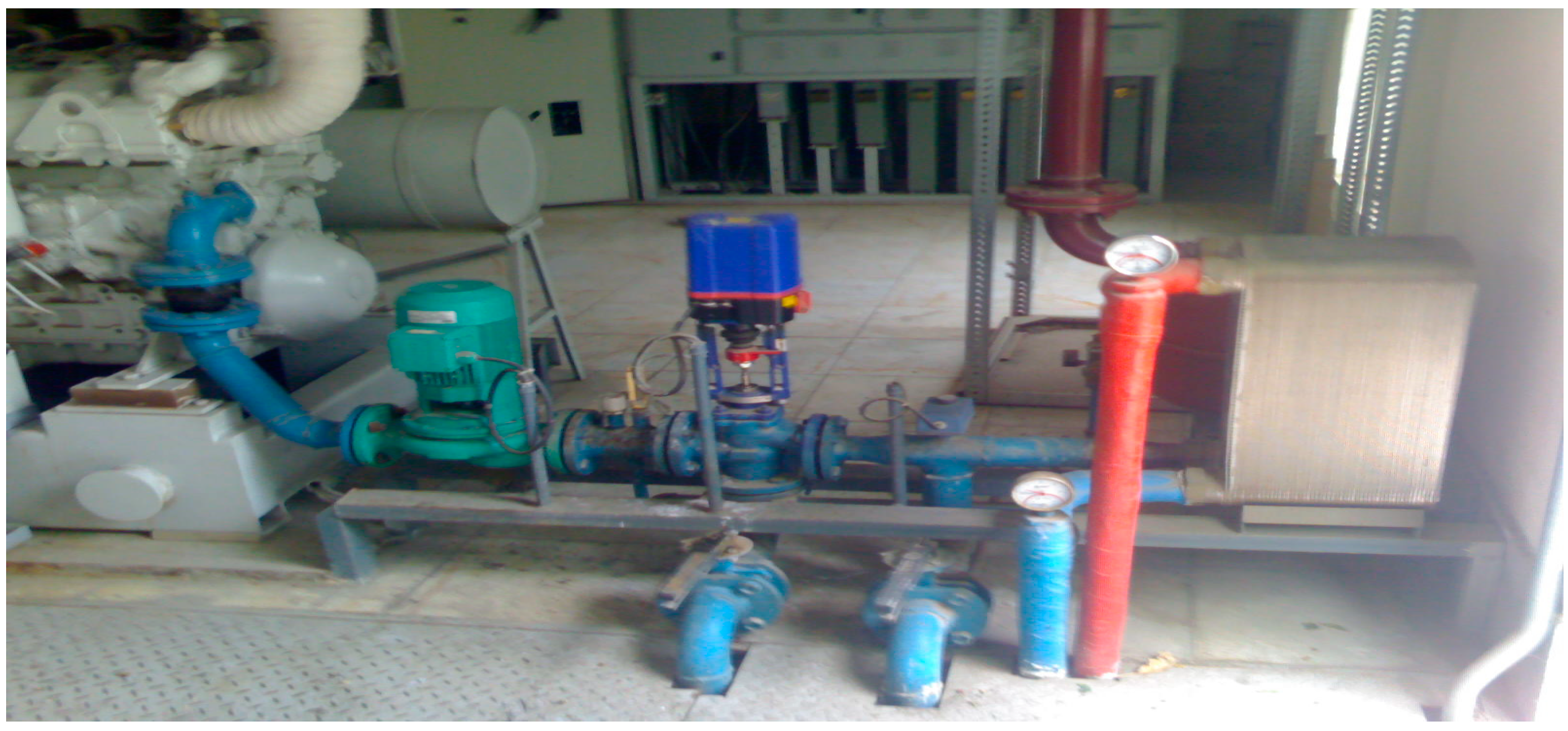
For cooling of IC engine, water was used ac cooling fluid. First water was circulated in closed loop in order to absorb heat from IC engine. Then water entered the exhaust gas heat exchanger to absorb thermal energy from exhaust gas. Schematic diagram of CHP heat exchanger is shown in
Figure 3 [
17].
Figure 3.
Schematic diagram of exhaust gas heat exchanger.
Figure 3.
Schematic diagram of exhaust gas heat exchanger.
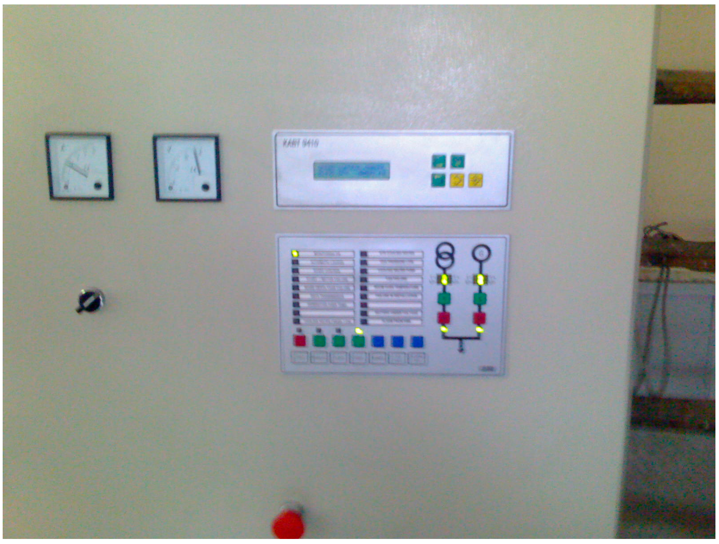
All of the system parameters, such as inlet and outlet cooling water temperature and pressure, inlet and outlet water temperature in CHP heat exchanger, fuel pressure, electrical power output, water, air and fuel mass flow rates, are shown in the control panel (
Figure 4).
Figure 4.
System control panel.
Figure 4.
System control panel.
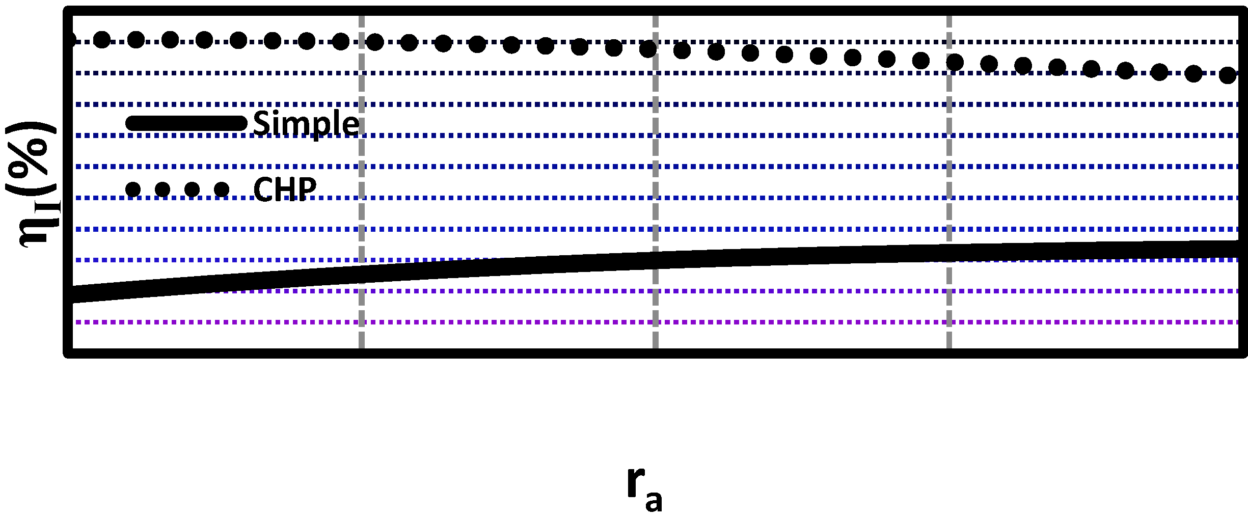
The variations of first law efficiency with excess air ratio for simple and CHP internal combustion engines are shown in
Figure 5. The form of the graph suggests that by increasing excess air ratio, the simple IC engine first law efficiency is increased but, for the type of combined power and heat production, this efficiency decreases.
Figure 5.
Variation of first law efficiency with excess air ratio for simple and CHP (combined heat and power) internal combustion engines at inlet air temperature of 15 °C.
Figure 5.
Variation of first law efficiency with excess air ratio for simple and CHP (combined heat and power) internal combustion engines at inlet air temperature of 15 °C.
By increasing air/fuel ratio, two opposite effects can be seen:
- (1)
Increasing air/fuel ratio mixture mass flow rate.
- (2)
Reduction combustion temperature.
Effect 1 can increase output power and effect 2 can decrease one. In simple IC engine combination of these two affects leads to increase in first law efficiency.
But in CHP IC engine, besides two previous effects, two other effects can be considered:
- (1)
Increasing exhaust mixture mass flow rate, that it causes increase heat exchanger efficiency.
- (2)
Reduce exhaust mixture temperature that it causes reduction in heat exchanger efficiency.
But item 2 has more effects than item 1, so it leads to decrease CHP IC engine efficiency by increase molar air fuel ratio.
The variations of entropy generation with excess air ratio for simple and CHP internal combustion engines are shown in
Figure 6. Due to the recovered heat in water jacket and exhaust gas heat exchangers, entropy generation in the CHP mode is lower than that in a simple internal combustion engine. By increasing the excess air ratio, the system entropy generation is decreased in both simple and CHP internal combustion engines. To obtain higher excess air ratios the air mass flow rate will be increased while the fuel mass flow rate remains constant. This increase causes the following effects:
- (1)
Increase in consumed compression work.
- (2)
Decrease in combustion temperature.
- (3)
Increase in produced expansion work.
- (4)
Increase in total mass flow rate to the IC engine (), which results in an increase in the net output power.
In a simple IC engine, the combination of these effects leads to a considerable decrease in entropy generation when the excess air ratio is increased. In a CHP IC engine the increase in the total mass flow rate (air and fuel mass flow rates) increases the effectiveness of both heat exchangers; hence the reduction in entropy generation is greater than that in a simple IC engine.
Figure 6.
Variation of entropy generation with excess air ratio for simple and CHP internal combustion engines at an inlet air temperature of 15 °C.
Figure 6.
Variation of entropy generation with excess air ratio for simple and CHP internal combustion engines at an inlet air temperature of 15 °C.
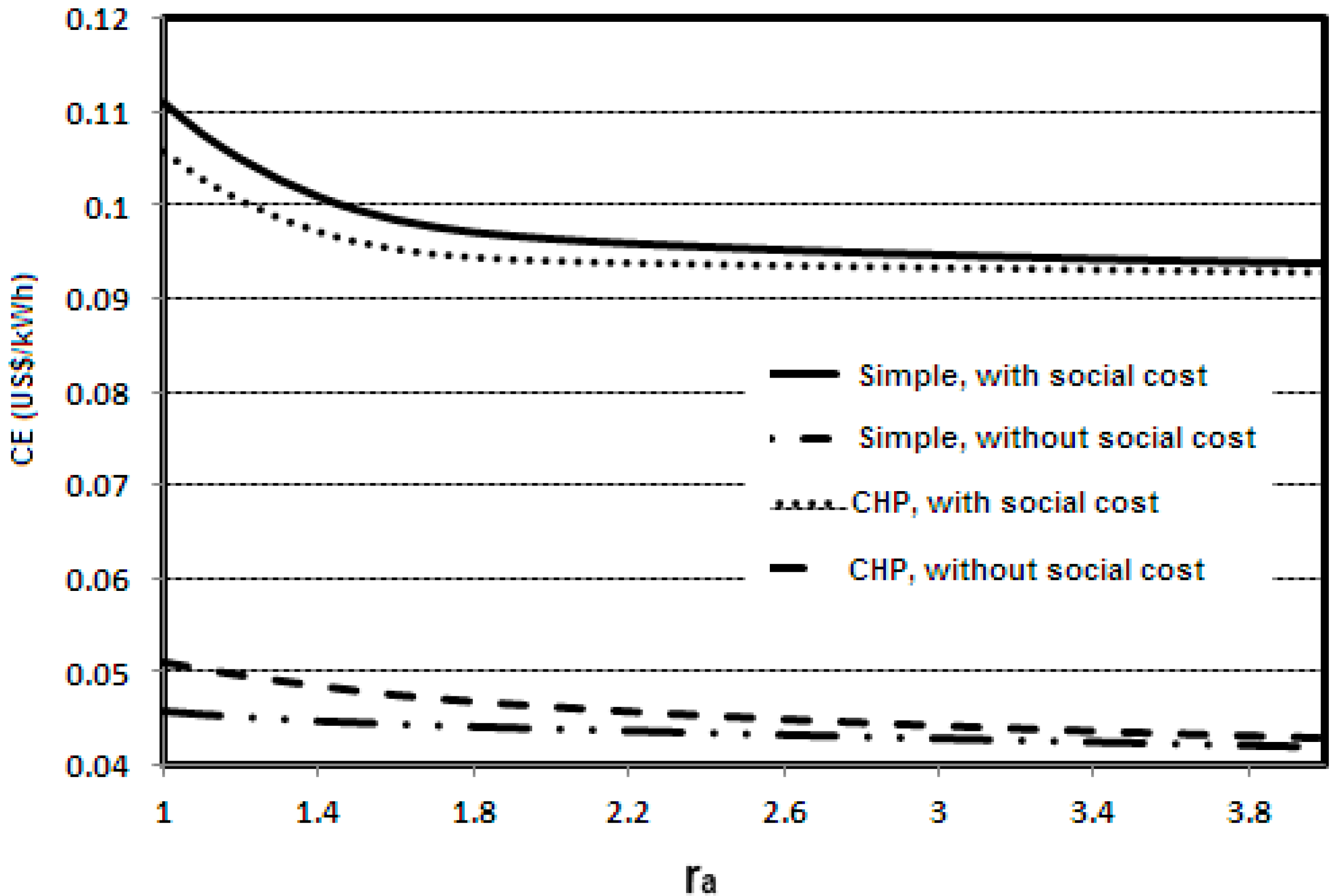
Figure 7 shows the variation of electricity cost (objective function with inclusion and exclusion of the external cost of air pollution) with excess air ratio for a simple and CHP IC engines at an inlet air temperature of 15 °C. Electricity cost is regarded as the objective function for computing the electricity cost for an IC engine. This function consists of four main parts: initial, operation and maintenance, fuel costs as well as the external cost of air pollution. This cost is added to the initial, operation and maintenance and fuel costs. Fuel cost and the external cost of air pollution depend on molar air-fuel ratio due to a variation of air pollution and the first law efficiency (Equations (23) and (24)), since these parameters are affected by molar air-fuel variation. It can be seen from
Figure 7 that by increasing the air-fuel ratio, the electricity cost decreases in both cases (inclusion and exclusion social cost air pollution). The average electricity cost with inclusion the social cost of air pollution increases 41% compared to when the electricity cost excludes the social cost of air pollution. In this research the highest value of the molar air-fuel ratio is considered to be 2, because at higher molar air fuel ratios combustion will not be achieved. In fact when flammability limits are observed the excess air ratio of 4 is optimum value. For CHP kind, the shape of that graph is similar to that for a simple IC engine; however this graph has a steeper slope. The cost of electricity for the CHP IC engine is less than for the simple one due to the reduction of the heat recovery heat cost from the cost of electricity. Contrary to exergy, the optimum value for electricity cost (objective function) has regional values because the external cost of air pollution depends on location of the plant and time of operation.
Figure 7.
Variation of electricity cost (with and without inclusion of the external cost of air pollution) with excess air ratio for a simple and CHP IC engines at an inlet air temperature of 15 °C.
Figure 7.
Variation of electricity cost (with and without inclusion of the external cost of air pollution) with excess air ratio for a simple and CHP IC engines at an inlet air temperature of 15 °C.


