1. Introduction
The conservation of collection materials inside any museum is a priority in the planning of indoor microclimate parameters; therefore, it requires particular environmental conditions, specifically the maintenance of definite ranges of temperature and Relative Humidity (RH) necessary to prevent damages to the museum objects [
1]. The design and installation of adequate Heating, Ventilation and Air Conditioning (HVAC) systems should be realized according to the maintenance of those temperature and RH ranges. In many historic buildings, these interventions should be realized tacking into account the conservation of the same building that in these cases represents itself part of the local historical heritage.
A study by Mecklenburg
et al. [
2] introduced the concept of preserving both the collections and the buildings, identifying the main requirements for control of the museum climate. In recent years, according to the European and Italian rules about energy efficiency in buildings, all the interventions should be aimed to a reduction of energy demand of the considered building. In fact, since 2013, with the Italian implementation of the Directive 2010/31/EU of the European Parliament and of the Council on the energy performance of buildings, all existing buildings subject to major renovation should therefore meet minimum energy performance requirements adapted to the local climate. In particular, for the purpose of optimizing the energy use of technical building systems, each European Member State shall set system requirements in respect of the overall energy performance, the proper installation, and the appropriate dimensioning, adjustment and control of the technical building systems installed in existing buildings. These requirements regard both the installation of renewable energy systems [
3] and the planning of strategies for the minimization of energy consumptions [
4,
5,
6,
7].
In recent years, with regard to the buildings energy efficiency, a new generation systems was developed. Among these, combined heat and power plants (CHP) represent promising solutions through the use of distributed electricity (DE) generation and waste energy recovery systems. In particular, considering CO
2 emissions, CHP using hydrogen enriched natural gas blends offer good environmental perspectives [
8,
9,
10,
11]. Unfortunately, as recently shown by the European project 3ENCULT (Efficient energy for EU cultural heritage), these technical solutions are not considered to be particularly suitable for historical buildings [
12]. In any case, for historical buildings no energy retrofit are mandatory in Italy; this attitude underlines that the energy performances are considered secondary to the conservation of the cultural heritage of the historical building.
Anyway, for an efficient and sustainable historic museum building refurbishment, the following factors should be jointly considered without neglecting any: collection materials conservation, historic building maintenance, visitor’s comfort and energy efficiency improvement.
According to ASHRAE (the American Society of Heating, Refrigerating and Air Conditioning Engineers) [
13], the following threats, in decreasing order of seriousness, affect all types of collections: Light damage, relative humidity (RH), temperature ranges, air pollution and contaminants, pest infestation, shock and vibration, natural emergencies, building and mechanical design malfunctions, theft and vandalism. In addition, ASHRAE [
13] underlines that older buildings have a higher risk of collection damage from condensation on windows, walls, and roofs. Therefore, HVAC applications in historic buildings must consider the risk to the structure and building envelope [
2].
In view of these considerations, the aim of the paper is to present a proposed method for energy recovery of an historic museum buildings, analyzing its current thermo-hygrometric conditions in order to maintain them within the ranges identified by ASHRAE for the conservation of collection materials [
13]. In particular, the method is finalized to the selection of the best system solutions feasible in the historic building under examination: the “Vittoriale degli Italiani”. In addition, the methodology includes an environmental impact assessment of the systems identified for the energy recovery, in order to select the most eco-friendly solution.
The “Vittoriale degli Italiani” is a hillside estate in Lombardy (north of Italy) under environmental, landscaping and historical constraints, which include an historic building “La Prioria”, containing collection materials and memorabilia in sumptuously decorated rooms. In particular, the methodology was applied for identifying feasible systems for the energy recovery of this historic building and consequentially increasing its thermo-hygrometric parameters to ASHRAE ranges without defacing its architectural heritage.
2. Methods
The methodology here described is aimed at the identification of the best system solutions for energy recovery interventions in the historic building under examination, obtaining a better control of the indoor environment for the conservation of collection materials, and preserving at the same time the historic building and the surrounding context [
2].
In particular, it foresees an analysis of the thermo-hygrometric conditions for the visitor’s thermal comfort [
14] and the conservation of collection materials, in the light of the legislation in force about energy efficiency parameters for existing buildings set by the European Directives as well as national and regional laws. In addition, the paper reports some indications about the feasibility of the installation of some system typologies in historic buildings and the environmental impacts related to each identified system solution.
Consequentially, it is first necessary to make an analysis of the national or local constraints of the area where the historic building under examination is located. This analysis can be easily made using GIS (Geographic Information System) software [
15,
16,
17,
18]. Furthermore, an examination of its current system typologies is required. In addition, the peculiar requirements for museums, jointly with the ones for public buildings should be considered. In particular: thermal comfort, energy saving for existing buildings restoration and microclimatic conditions for the conservation of collection materials. Nowadays, designers mainly take into account the first requirements with the main aim of energy recovery of existing buildings. Anyway, considering an historic building and museums, the latter requirement, conditions for the conservation of collection materials, assumes a greater importance.
2.1. Monitoring of Hygrothermal Parameters
Considering that an inadequate dehumidification is the most common problem for the conservation of collection materials in historic buildings and museums, it is essential the monitoring of hygrothermal parameters [
19]. Michalski [
20] summarizes the ASHRAE approach for the identification of the temperature and RH ranges in general museums, art galleries, libraries, and archives, indicating the probable effects of various specification options (
Table 1).
Table 1.
Temperature and Relative Humidity Specifications for Collections in general museums, art galleries, libraries, and archives (adapted from [
13]).
Table 1.
Temperature and Relative Humidity Specifications for Collections in general museums, art galleries, libraries, and archives (adapted from [13]).
| Class of Control | Short Fluctuations Plus Space Gradients | Seasonal Adjustments in System Set Point | Collection Risks and Benefits |
|---|
| AA-Precision control, no seasonal changes | ±5% RH, ±2 K | RH no change Up 5 K; down 5 K | No risk of mechanical damage to most artifacts and paintings. Some metals and minerals may degrade if 50% RH exceeds a critical relative humidity. Chemically unstable objects unusable within decades. |
| A-Precision control, some gradients or seasonal changes, not both | ±5% RH, ±2 K | Up 10% RH, down 10% RH Up 5 K; down 10 K | Small risk of mechanical damage to high vulnerability artifacts; no mechanical risk to most artifacts, paintings, photographs, and books. Chemically unstable objects unusable within decades. |
| ±10% RH, ±2 K | RH no change Up 5 K; down 10 K |
| B-Precision control, some gradients plus winter temperature setback | ±10% RH, ±2 K | Up 10%, down 10% RH Up 10 K, but not above 30 °C | Moderate risk of mechanical damage to high vulnerability artifacts; tiny risk to most paintings, most photographs, some artifacts, some books; no risk to many artifacts and most books. Chemically unstable objects unusable within decades, less if routinely at 30°C, but cold winter periods double life. |
| C-Prevent all high risk extremes | Within 25 to 75% RH year-round Temperature rarely over 30 °C, usually below 25 °C | High risk of mechanical damage to high vulnerability artifacts; moderate risk to most paintings, most photographs, some artifacts, some books; tiny risk to many artifacts and most books. Chemically unstable objects unusable within decades, less if routinely at 30°C, but cold winter periods double life. |
| D-Prevent dampness | reliably below 75% RH | High risk of sudden or cumulative mechanical damage to most artifacts and paintings because of low-humidity fracture; but avoids high-humidity delamination and deformations, especially in veneers, paintings, paper, and photographs. Mold growth and rapid corrosion avoided. Chemically unstable objects unusable within decades, less if routinely at 30°C, but cold winter periods double life. |
| Maximum fluctuations and gradients in controlled spaces. Set point or annual average: 50% RH (or historic annual average for permanent collections). Temperature set between 15 °C and 25 °C. Note: Rooms intended for loan exhibitions must handle set point specified in loan agreement, typically 50% RH, 21 °C, but sometimes 55% or 60% RH. |
As reported in
Table 1, the permissible fluctuation of hygrothermal parameters has been divided into five classes, from AA to D, in descending order of accuracy. Class AA control has the highest potential for energy consumption and affords no protection to historic buildings in cold climates. Class A, which gives two possibilities with equivalent risks, is the optimum for most museums and galleries. Classes B and C are useful and feasible for historic building, as well as for medium or small institutions. Class D recognizes that control of dampness is the only climatic issue [
13].
Considering the potential damage to the collection materials a critical factor is the velocity and the duration of the hygrothermal parameters variation. In fact, a 20% RH variation in 4 months is less prejudicial than a 10% RH variation within a week [
13].
Since the overall objective of plant interventions in a museum is the conservation of its cultural heritage, the methodology foresees the monitoring of the hygrothermal conditions of each internal space of the analyzed historic building. This monitoring phase should be realized recording temperature and HR [
21] in each room by means of an appropriate equipment, according to the indications reported in the Italian Committee for Standardization UNI 10829:1999 “Works of art of historical importance—Ambient conditions or the conservation—Measurement and analysis”.
It will be possible in this way to evaluate the concrete conditions derived by the plants installed in the building, in order to highlight eventual criticalities in any single space.
In particular, the equipment included portable measurement instruments containing a multiple data acquisition device (Babuc data logger), able to automatically recognize the connected sensors to measure temperature and RH. Babuc instruments, which have been previously used for the same measurements in other similar scientific studies [
22,
23,
24], have to be connected to a hot wire anemometer sensor, psychometric sensors for thermo-hygrometric quantities and mean radiant temperature calculation. All the above-mentioned equipment is consistent with ISO Standard 7726 requirements [
25]. The temperature and RH values recorded will be then compared with the values recommended in Appendix A of the UNI 10829:1999: indoor temperature could range between 19 °C and 24 °C, and RH between 40% and 50%. Therefore, it is important to check that the measured temperatures and RH values in the summer does not exceed the ceiling and in the winter does not fall below the minimum.
2.2. Identification of the Possible System Solutions
According to
Table 1, considering functions and requirements of any indoor space, the system should be sized to provide the amount of heating or cooling needed to maintain desired temperature and RH [
26]. Therefore, the design cooling and heat loads should be calculated following the strengthened procedures [
27] and in particular taking into account the following parameters essential for the historic building containing collection materials [
13]:
- -
The optimal thermo-hygrometric ranges for the historic building according with UNI 10829:1999 “Works of art of historical importance-Ambient conditions or the conservation-Measurement and analysis”.
- -
Building materials’ characteristics according to the indications of the UNI EN ISO 10456:2008 “Building materials and products-Hygrothermal properties-Tabulated design values and procedures for determining declared and design thermal values”.
- -
Average crowding to estimate according with the particular rules for visitors of the historic building under analysis.
- -
An appropriate ventilation for rooms open to visitors should vary between 0.5 air changes per hour in winter and 1 air change per hour in summer; while for archives not open to the public, 0.2 air changes per hour could be considered [
28].
In the following conditions, the design heat load could be assessed with a simplified calculation reported in the UNI EN 12831:2006 “Heating systems in buildings - Method for calculation of the design heat load”: the outside temperature is always considerably lower than the indoor one, generating an unidirectional heating load; the variation of the external temperature is not greater than a few degrees; the indoor temperature can be considered constant; internal loads and solar heat gains act so as to reduce the design heating load. In these cases, the design heat load for a thermal zone can be calculated using the Equation (1).
where:
i: i-th homogeneous thermal zone in which the heated volume is possibly divided
: heat load of the i-th thermal zone in Watt (W)
: design transmission heat loss for heated space of the i-th thermal zone in Watt (W)
: design ventilation heat loss for heated space of the i-th thermal zone in Watt (W)
: heating-up capacity required to compensate for the effects of intermittent heating of the i-th thermal zone in Watt (W).
Consequentially, the total design heat load for a building can be obtained using Equation (2).
The design cooling load can be calculated using the CLTD (cooling load temperature different) method by multiplying it with the UA-value of the analyzed building element (Equation (3)).
where Q is the cooling load (W), U is the overall heat transfer coefficient of the building wall or roof (Wm
−2 K
−1), S is the surface area of external wall or roof (m
2) and CLTD is the cooling load temperature difference (K). CLTD corresponds to an equivalent temperature difference used for calculating the instantaneous external cooling load across a roof or a wall [
29,
30]. Its values are found from tables designed for fixed conditions such as outdoor/indoor temperatures and latitudes [
30]. In addition, for the design cooling load the following parameters should be considered: average occupation, internal gains and lighting [
31].
Once calculated the design heating and cooling load, the design process of an air conditioning system is thus performed through the following six steps: (1) specifications (technical standards) recognition; (2) heat and cooling load calculation; choice of the adequate system typology; (3) sizing of system components; (4) system layout planning; (5) sizing of fluids distribution networks; (6) choice of regulation and control systems.
Considering that the system to select has to be installed in an historic building, the installation of air handling units (AHU) should be usually avoided due to their impact on an historic building, even if AHU provide excellent performances in terms of control of the temperature and RH values. In fact, the voluminous air shafts of these systems can hardly be placed in a building that did not already provide them when it was designed. Moreover, the air-handling unit of these systems is not easily integrated in a building under landscape and historical constraints. Even air-water systems have the same drawbacks, since they equally need air shafts which, albeit smaller than those required for all air conditioning systems, impact significantly on any historic building.
Remain water systems and air conditioning direct expansion systems; among direct expansion system, splits and single-units should be excluded since their known visual impact on building facades does not suit with historic buildings. In addition, the selected system should provide an appropriate control system of the thermal power lead input into the building, which depends on the different and variable dispersion conditions. Among the identified plant solutions, the first choice should be for the most eco-friendly plant typology that could be identified using the Life Cycle Assessment (LCA) method for assessing the environmental impact of products and services over their life cycles.
2.3. LCA Analysis of the Selected Plant Typologies
The environmental impacts of heating, ventilating and air-conditioning (HVAC) systems [
32,
33,
34] are usually evaluated by LCA methods with a multi-criteria analysis point of view [
35]; among these, the Ecoindicators 99 method, elaborated for the Holland Environmental Ministry by the Product Ecology Consultants, assesses the LCA by means of three damage categories: Human health, ecosystem quality and resources consumptions [
36,
37,
38]. This method considers both the production and the decommissioning phase, and can be applied to air conditioning systems [
39], but only in Europe, since all the coefficients and weights of all the parameters are specifically calculated for European countries. Each damage category has its own unit measure. Human health is expressed in DALY (Disability-Adjusted Life Year), combining the number of year life lost and the number of year lived disabled [
36] and considers damages caused by carcinogenic substances, respiratory effects, climate change, ionizing radiation, and ozone layer depletion; this index is also used by the WHO and the World Bank. Ecosystem quality is expressed in PDF × m
2 × year, where PDF is the Potentially Disappeared Fraction [
35], and considers damages caused by ecotoxic substances, acidification, eutrophication and land use. Lastly, resources consumption, which considers the surplus energy needed or future extractions of minerals and fossil fuels, is expressed in MJ [
40].
However, the damage values of the three categories are normalized in millipoints (mPt) using a weighting procedure specifically elaborated [
40]. Therefore, using this method, the Life Cycle Assessment value of each component is derived from the sum of the mPt value of each one of the three damage categories. Consequentially, the LCA value of a system derives from the sum of the LCA values of each of its component [
41]. The values for each component in its phases of production and decommissioning are available using the SimaPro software, considered, jointly with GaBi, the leading software tools used for life cycle assessments [
42].
3. Results and Discussions
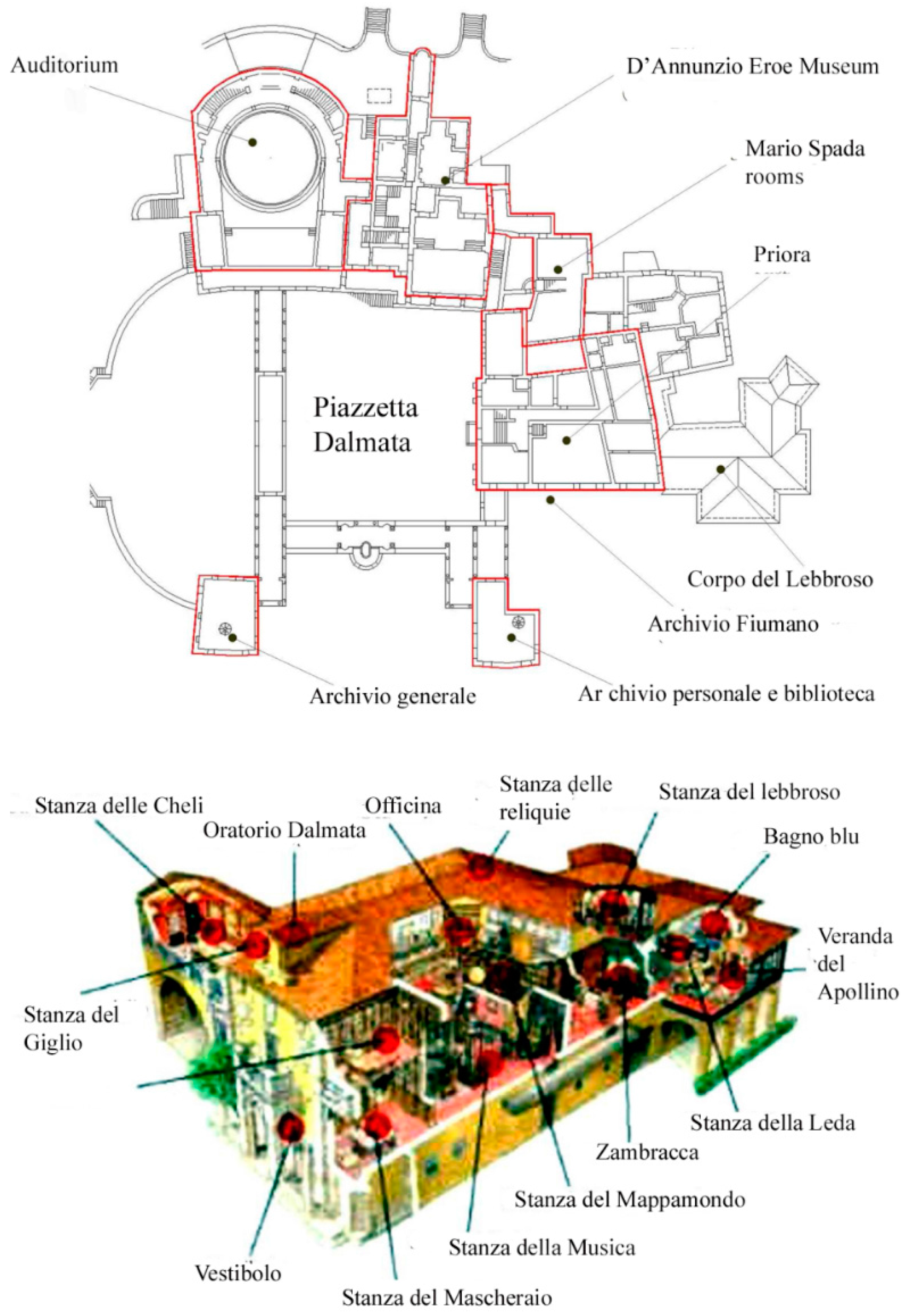
The above-described methodology has been applied as a case study to the “Vittoriale degli Italiani” historic building, which functions are comprised of conservation, promotion and fruition activities. In particular, the case study was realized analyzing “La Prioria”, the main historic building of the site, where lived the Italian poet Gabriele D’Annunzio (
Figure 1), taking into account the different peculiarities and usages of each room.
Figure 1.
Plan of the The Vittoriale degli Italiani and a perspective drawing of the indoor areas of La Priora historic building.
Figure 1.
Plan of the The Vittoriale degli Italiani and a perspective drawing of the indoor areas of La Priora historic building.
Considering the local constraints of the Vittoriale degli Italiani case study, it is subject to the energy efficiency rules for buildings of the Lombardia Region which include more restrictive limits in respect to the Italian ones (Regional law 24 of 2006 about rules for emissions prevention and reduction; regional law 8/5018 of 2007 about energy performance certificate). In addition, the performances required for the redevelopment of technological systems and envelopes of historic buildings should be consistent with the maintenance of the thermo-hygrometric parameters needed for the conservation of the collection materials safeguarded in the building.
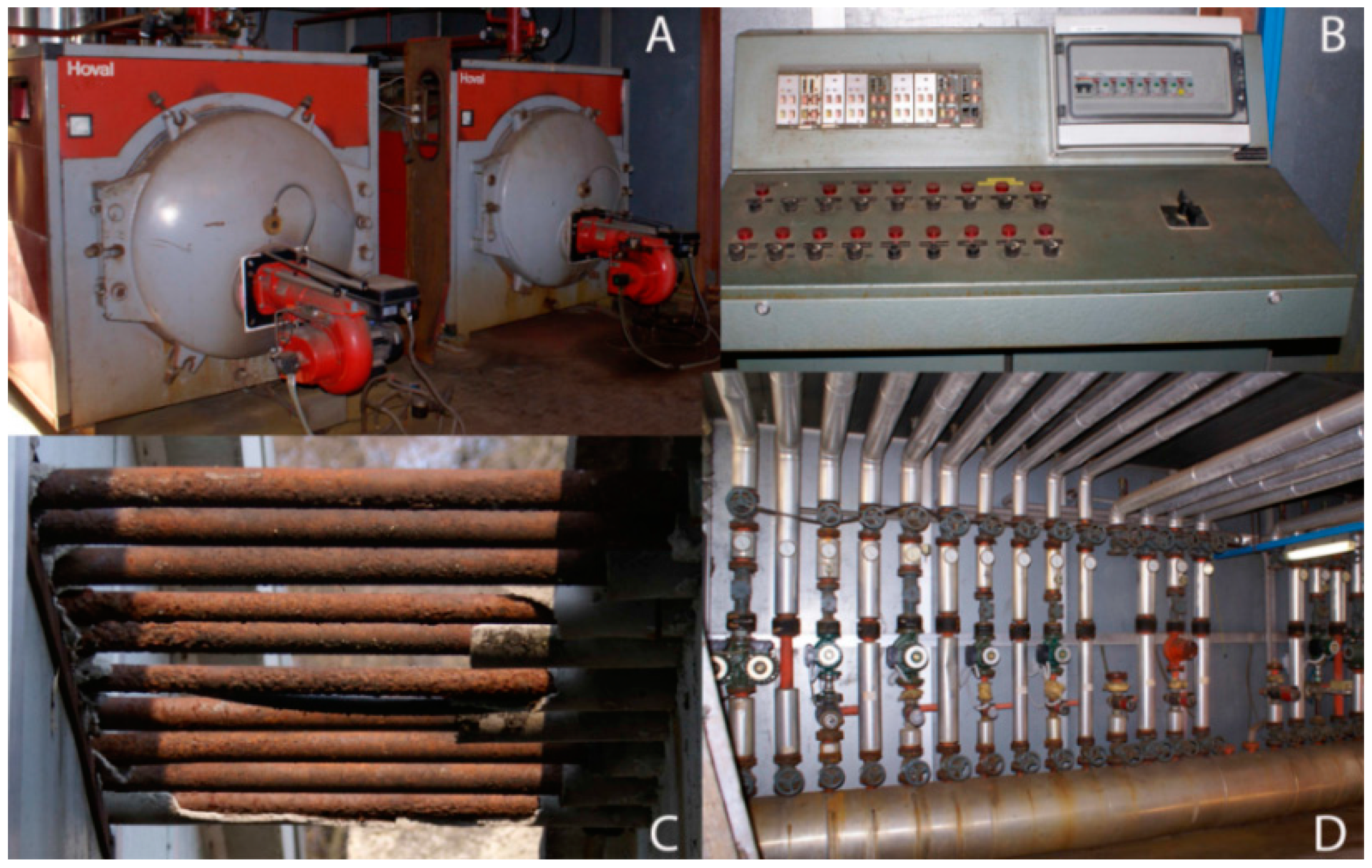
The current central heating plant includes two oil boilers of 520 kW each (
Figure 2a) for all the “Vittoriale degli Italiani complex”. One of the two oil boilers has been decommissioned while the other is in operation.
Figure 2b shows the electrical panel that check the generators and the circulation pumps where are connected the pipes for the different zones,
Figure 2c,d shows the evidently deteriorated current status of the outdoor sections of the pipes that may cause a water loss. Moreover, from the analysis of the plant typologies currently in the museum, the Vittoriale degli Italiani complex includes several autonomous heating systems, that come from a previous single installation, from which, over the years, different sections have been disconnected.
Figure 2.
(a) current central heating plant; (b) electrical panel; (c) outdoor sections of the system pipes; (d) system generators and circulation pumps.
Figure 2.
(a) current central heating plant; (b) electrical panel; (c) outdoor sections of the system pipes; (d) system generators and circulation pumps.
3.1. Hygrothermal Parameters Monitoring
The thermo-hygrometric data gathering in the Vittoriale degli Italiani historic buildings noted a number of conditions that can affect the long-term preservation of its collection materials.
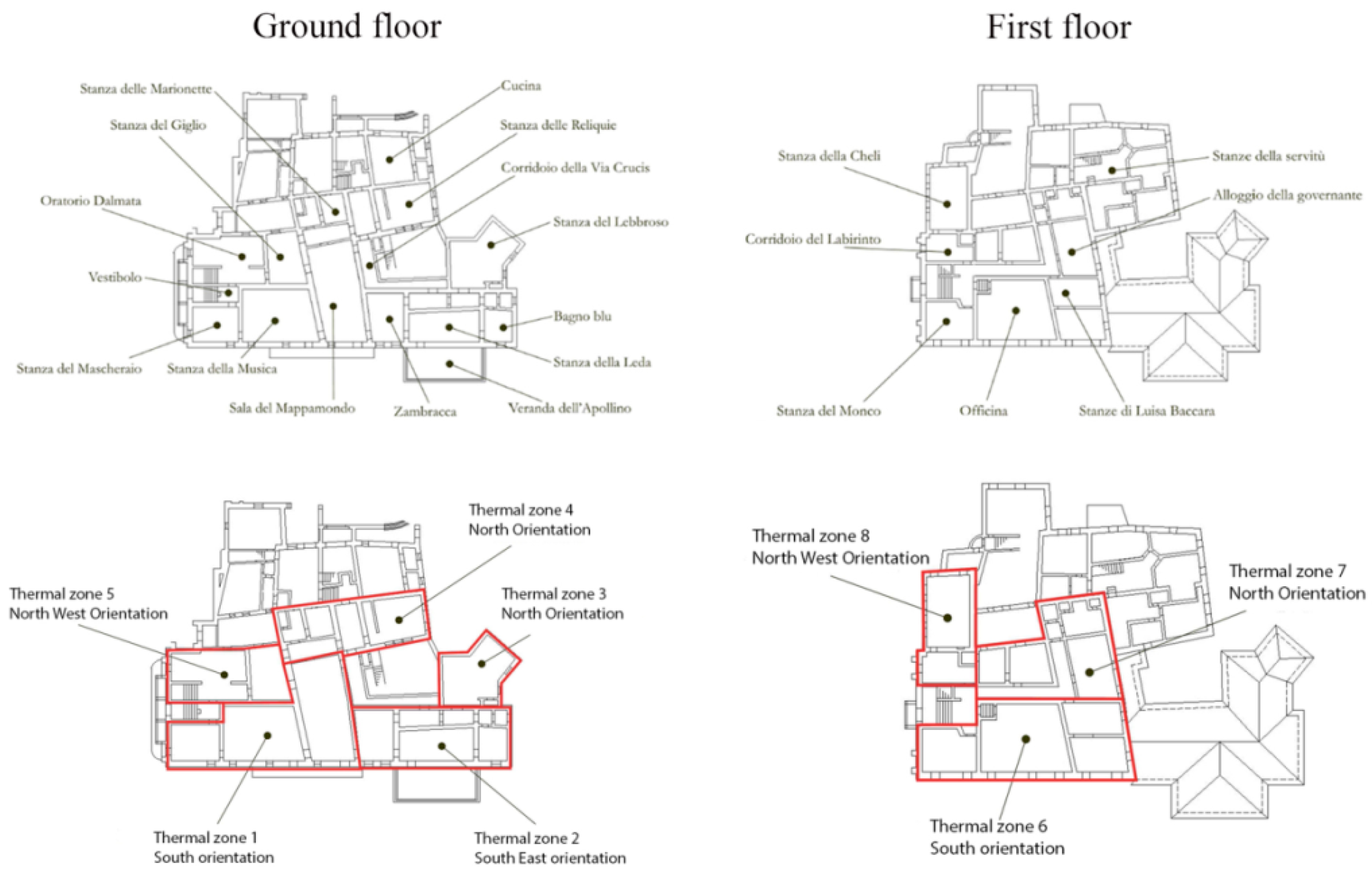
The indoor rooms currently heated were grouped into 17 thermal zones, considered homogeneous in terms of dispersion and exposure. The first eight are situated in the two floors of the Prioria building (
Figure 3).
Figure 3.
Homogeneous thermal zones of the Priora historic building in the Vittoriale degli Italiani.
Figure 3.
Homogeneous thermal zones of the Priora historic building in the Vittoriale degli Italiani.
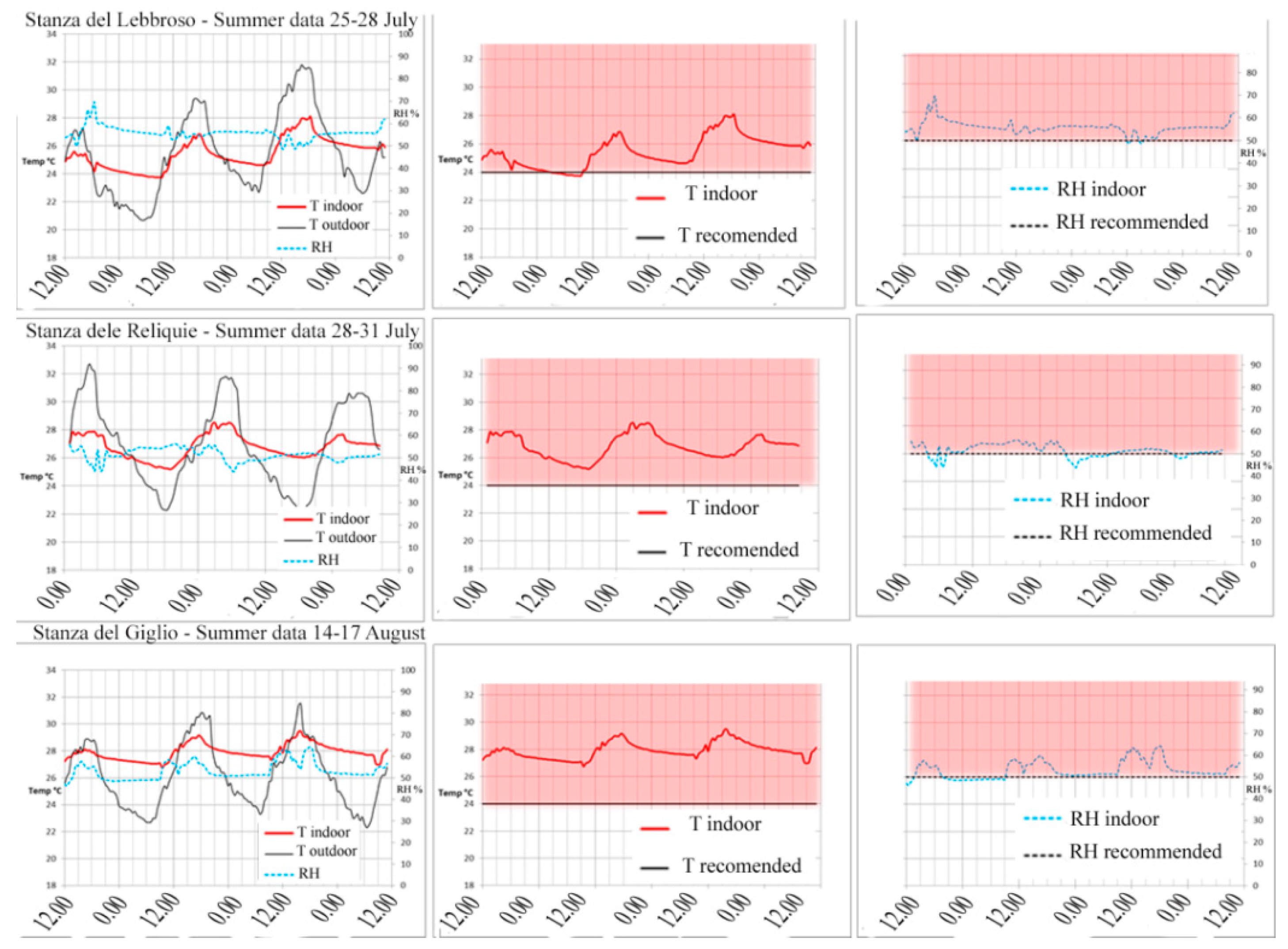
Two data gathering campaigns, one in summer and one in winter were conducted recording temperature and RH values in the following rooms of La Priora: Stanza del Lebbroso (thermal zone 3), Stanza delle Reliquie (thermal zone 4), Stanza del Giglio (thermal zone 5), Stanza del Mappamondo (thermal zone 1), Stanza della Cheli (thermal zone 8) and Officina (thermal zone 6). Both in summer and in winter instruments for data gathering are moved from a room to another every three days, obtaining the results summarized in
Figure 4,
Figure 5,
Figure 6 and
Figure 7.
Figure 4.
Comparing Temperature and RH Summer data in Stanza del Lebbroso, Stanza delle Reliquie e Stanza del Giglio with UNI 10829 recommended values.
Figure 4.
Comparing Temperature and RH Summer data in Stanza del Lebbroso, Stanza delle Reliquie e Stanza del Giglio with UNI 10829 recommended values.
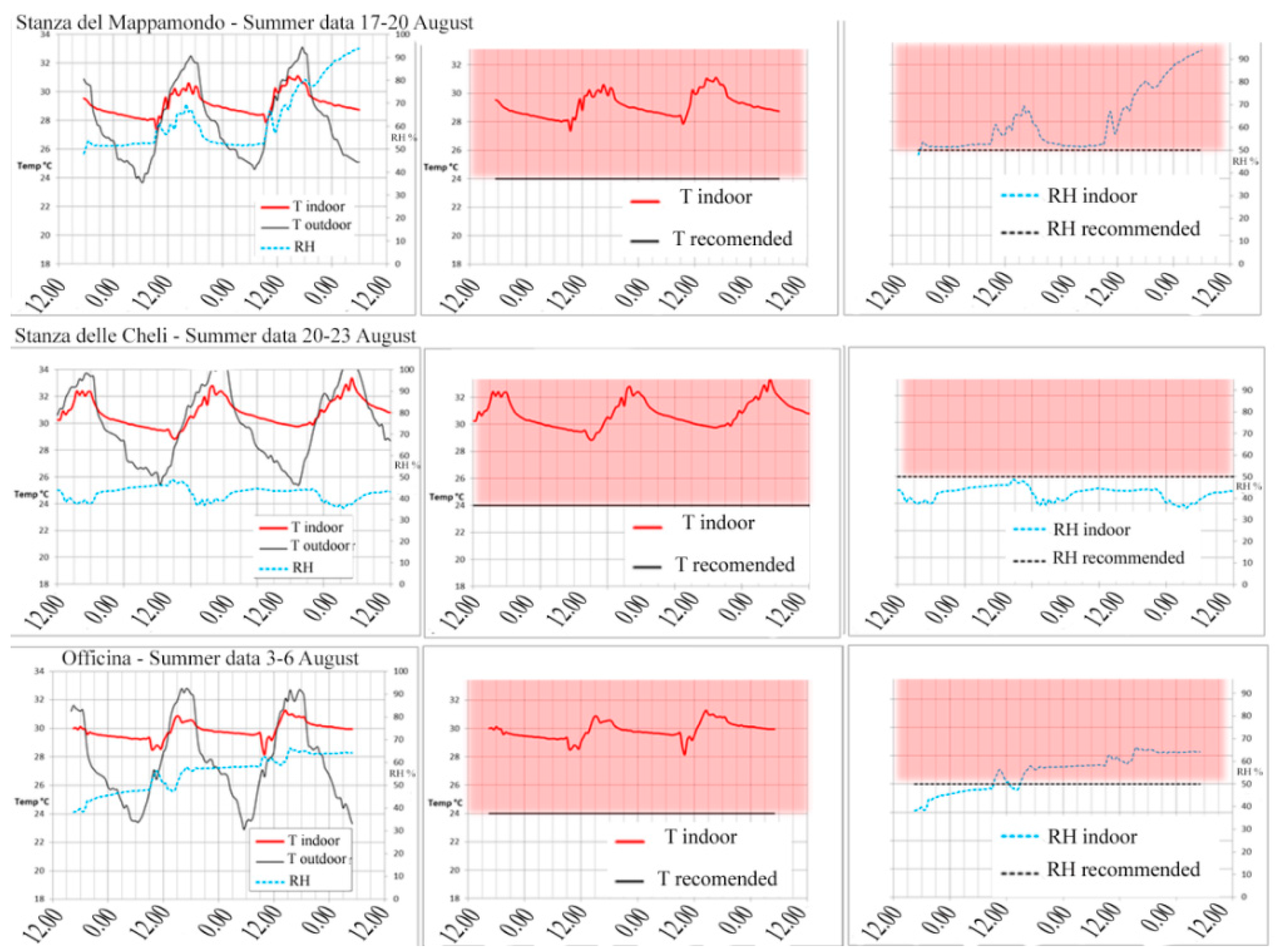
Figure 5.
Comparing Temperature and RH Summer data in Stanza del Mappamondo, Stanza delle Cheli and Officina with UNI 10829 recommended values.
Figure 5.
Comparing Temperature and RH Summer data in Stanza del Mappamondo, Stanza delle Cheli and Officina with UNI 10829 recommended values.
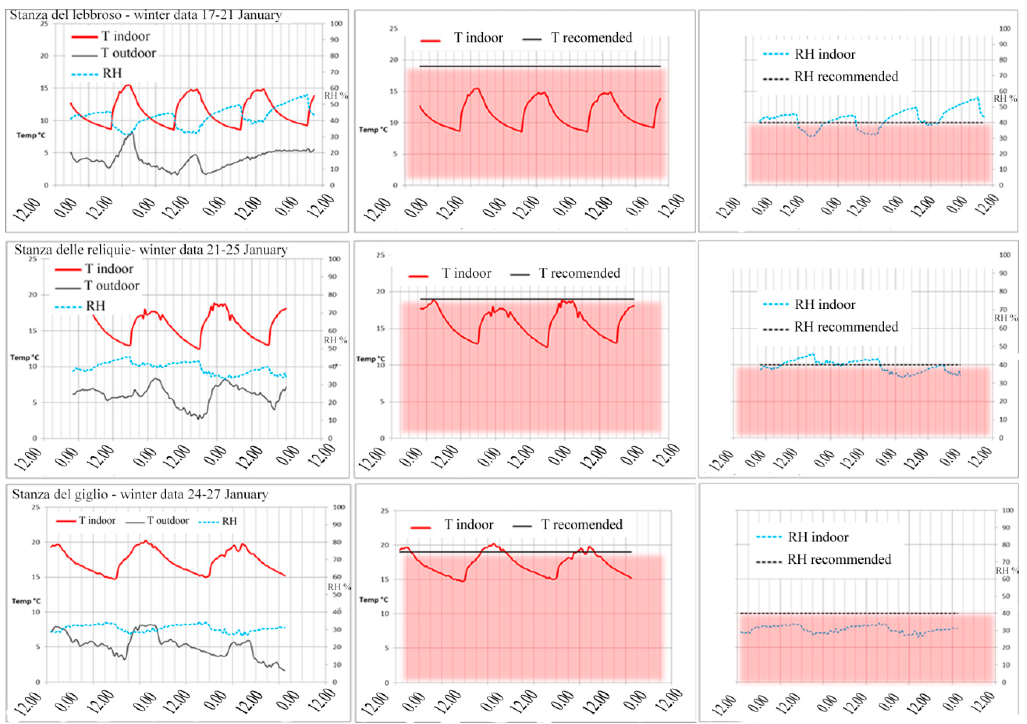
Figure 6.
Comparing Temperature and RH Winter data in Stanza del Lebbroso, Stanza delle Reliquie e Stanza del Giglio with UNI 10829 recommended values.
Figure 6.
Comparing Temperature and RH Winter data in Stanza del Lebbroso, Stanza delle Reliquie e Stanza del Giglio with UNI 10829 recommended values.
Figure 7.
Comparing Temperature and RH Summer data in Stanza del Mappamondo, Stanza delle Cheli and Officina with UNI 10829 recommended values.
Figure 7.
Comparing Temperature and RH Summer data in Stanza del Mappamondo, Stanza delle Cheli and Officina with UNI 10829 recommended values.
Figure 4,
Figure 5,
Figure 6 and
Figure 7 clearly shows, both in summer and in winter, the moment in the morning at the beginning of human activities when the windows are opened, evidenced by sudden changes in temperature and RH values. Moreover, from the comparison with recommended values it is possible to verify that both in summer and in winter indoor temperature and RH values are almost always in the discomfort area, highlighted in red, underlining a critical situation for the conservation of the materials in each room due to the inadequacy of the current system typology. The critical situation is aggravated comparing the temperature and RH variations recorded during the three days data gathered in each room and season with UNI 10829 recommended values. In fact, the recorded variations, both for temperature as for RH, reported in
Table 2, are normally higher than the values recommended by UNI 10829: ΔT (°C) = 1.5; ΔRH (%) = 4–6.
Table 2.
Temperature and RH variations recorded in each analyzed room during summer and winter data gathering campaigns.
Table 2.
Temperature and RH variations recorded in each analyzed room during summer and winter data gathering campaigns.
| Room | SUMMER DATA | Winter Data |
|---|
| ΔT (°C) | ΔRH % | ΔT (°C) | ΔRH % |
|---|
| Stanza del Lebbroso | 4.33 | 21.00 | 6.93 | 24.80 |
| Stanza delle Reliquie | 3.33 | 12.30 | 6.52 | 12.90 |
| Stanza del Giglio | 2.71 | 18.10 | 5.53 | 8.20 |
| Stanza del Mappamondo | 3.75 | 49.00 | 5.80 | 10.90 |
| Stanza della Cheli | 4.52 | 13.10 | 6.71 | 13.40 |
| Officina | 3.11 | 28.00 | 5.19 | 5.10 |
3.2. Identification of the Possible System Solutions
Table 3 and
Table 4 summarize the design heat and cooling loads assessed for each of the 8 thermal zones of the Prioria building.
Table 3.
Design heat loads of the eight thermal zones of the Priora building.
Table 3.
Design heat loads of the eight thermal zones of the Priora building.
| Thermal Zone | Volume (m3) | Heat Load (W) | Heat Load Per m3 (W/m3) |
|---|
| 1 | 547.92 | 8000 | 14.60 |
| 2 | 373.72 | 6037 | 16.15 |
| 3 | 167.76 | 6118 | 36.47 |
| 4 | 318.28 | 8019 | 25.19 |
| 5 | 283.96 | 6594 | 23.22 |
| 6 | 332.48 | 10,220 | 30.74 |
| 7 | 260.74 | 7089 | 27.19 |
| 8 | 209.48 | 7654 | 36.54 |
| Total | 2494.34 | 59,731 | 23.95 |
Table 4.
Design cool loads of the eight thermal zones of the Priora building.
Table 4.
Design cool loads of the eight thermal zones of the Priora building.
| Cooling Load (W) |
|---|
| Thermal Zone | 1 | 2 | 3 | 4 | 5 | 6 | 7 | 8 | Total |
|---|
| Hours |
|---|
| 6 a.m. | 3665 | 1207 | 1784 | 2857 | 1816 | 2568 | 1691 | 4023 | 19,701 |
| 7 a.m. | 3324 | 1385 | 1643 | 3288 | 1424 | 2946 | 1917 | 2088 | 18,015 |
| 8 a.m. | 3879 | 1951 | 1655 | 3811 | 1308 | 3560 | 1993 | 1665 | 19,822 |
| 9 a.m. | 4593 | 3838 | 1707 | 5232 | 2299 | 5717 | 3367 | 2162 | 28,915 |
| 10 a.m. | 5194 | 4221 | 1657 | 5134 | 2367 | 6038 | 3264 | 2171 | 30,046 |
| 11 a.m. | 5767 | 4532 | 1556 | 4831 | 2462 | 6241 | 3123 | 2223 | 30,735 |
| 12 a.m. | 6146 | 4712 | 1513 | 4596 | 2578 | 6338 | 3052 | 2423 | 31,358 |
| 1 p.m. | 6344 | 4762 | 1744 | 4592 | 2764 | 6345 | 3135 | 3161 | 32,847 |
| 2 p.m. | 6189 | 4458 | 2013 | 4470 | 3050 | 6011 | 3219 | 4369 | 33,779 |
| 3 p.m. | 6290 | 4366 | 2228 | 4473 | 3309 | 5884 | 3250 | 5460 | 35,260 |
| 4 p.m. | 5767 | 3817 | 2350 | 4071 | 3444 | 5293 | 3181 | 6234 | 34,157 |
| 5 p.m. | 5302 | 3412 | 2379 | 3724 | 3448 | 4855 | 3111 | 6368 | 32,599 |
The estimated average crowding was of 0.1 people per square meter for the Prioria building. Since its total surface is 700 m2, this value derives from the observation that, during the season of maximum visitors’ inflow (summer months), the Prioria can host a maximum of 7 groups of 10 people each.
In the light of the high thermo-hygrometric values reported in the above paragraph, and considering the assessed design heat and cooling loads, it is of the utmost importance to plan the best possible measures to minimize the potential degradation of the historic heritage preserved inside the building. In fact, the RH values are held in check only in one of the 17 thermal zone, the “Fiumano” archive (thermal zone 9, not included in the Prioria building), recently equipped with an air conditioning system calibrated for the maintenance of about 40% of UR; the remaining spaces are at the mercy of the exposures and conditions of use.
Consequentially, considering the discriminatory methods for the system selection described in paragraph 2.2, two possible system solutions, able to ensure the required temperature and RH values, loom. The first is a hydronic fan coil system where the water is heated or cooled in a central heating and cooling plant and sent to the heat exchangers, the fan coil units. In order to make them not visible, the fan coils could be easily recessed in the boiseries where are currently installed the radiators. The fan coil units should be regulated with room thermostats able to interact with fan switches or with a two way modulating valve placed in the hydraulic circuit upstream of the heating and cooling coil. In the latter case it has the drawback of making a variable system flow rate. This inconvenience could be avoided substituting the two way modulating valve with a three way diverter valve or installing electronically controlled pumps. Each fan coil can be equipped with a wall outlet to enter into the room a certain air flow from outside modulated by the users through an adjustable shutter. In order to avoid problems of freezing during the winter season, a mixture of water and glycol should be used as carrier fluid. A possible variant to the fan coils as heat exchangers are underfloor heating pipes. However, recognizing the invasiveness of these installations, this solution is recommended only in cases of restoration works.
The second system typology suitable for the historic building under analysis, is a direct-expansion (DX) air-conditioning (A/C) system, mainly composed of two parts, a DX refrigeration plant (refrigerant side) and an air distribution sub-system (air side). Moreover, in order to improve its operating performance and energy efficiency, a SPM (semi-physical model) based controller for the simultaneous control of air temperature and humidity [
43] or a multi input multi-output (MIMO) control strategy could be used for simultaneously controlling the indoor air temperature and RH by varying compressor speed and supply fan speed of the DX A/C system [
44]. In fact, the performance of conventional single-input single-output (SISO) control strategies is inferior to that of MIMO control strategies [
45]. In particular, the MIMO control system uses two feedback signals
(i.e., indoor air temperature and moisture content) to generate two signals for controlling simultaneously both compressor speed and supply fan speed [
44].
This kind of system could be a more efficient solution for maintaining the required thermo-hygrometric parameters, because:
- -
The thermoventilating units in DX A/C systems are similar to the fan coils of a hydronic system but the piping system are covered by a gaseous refrigerant which would prevent flooding in the event of piping leaks in collection areas.
- -
It is possible to have a two-way data communication with the central heating and cooling plant, greatly expanding the possibilities of the system regulation and allowing the control of temperature and RH of each thermal zone, even in the case of a heat and a cool load in two thermal zones connected to the same central heating and cooling plant.
In addition, the generation could be divided into subsystems, with the obvious benefit of system performance, but, in this case, a redo of the power lines is necessary.
3.3. LCA Analysis of the Selected Plant Typologies
Comparing the two system solutions proposed in the above paragraph, the first can be considered more traditional, while the latter is more innovative; hence, as described in
Section 2.3, the final choice should take into account the environmental impacts of both solutions estimated with the LCA method.
In particular, the assessment of the environmental impact of a hydronic fan coil system, calculated trough the Ecoindicator 99 method is summarized in
Table 5, while the environmental impact of a multiple-split direct-expansion air-conditioning system is showed in
Table 6.
Table 5 and
Table 6 provide the opportunity to compare the value of the environmental impact of each considered system typology, becoming a useful tool for the comparison with other possible solutions for other buildings of architectural and historical value. In this case, the LCA analysis shows that the installation of a multiple-split direct-expansion air-conditioning system produce a lower environmental impact compared to a hydronic fan coil system.
Table 5.
Life Cycle Assessment of a hydronic fan coil system per kW.
Table 5.
Life Cycle Assessment of a hydronic fan coil system per kW.
| Component | Human Health | Ecosystem Quality | Resources Consumption | Life Cycle Assessment |
|---|
| mPt per unit of measure | mPt per kW | mPt per unit of measure | mPt per kW | mPt per unit of measure | mPt per kW | mPt per kW |
|---|
| Production Phase |
| Heat pump (kWt) | 5519.1 | 5519.1 | 2467 | 2467 | 9,910 | 9910 | 17,896.1 |
| Air handling unit (m3/h) | 58.1 | 6797.7 | 16.7 | 1953.9 | 129.6 | 15,163.2 | 23,914.8 |
| Steel pipes (Kg) | 119.4 | 1385.04 | 20.9 | 242.44 | 271.3 | 3147.08 | 4774.56 |
| Galvanized sheet metal duct (Kg) | 144.5 | 4190.5 | 119.9 | 3477.1 | 301.4 | 8740.6 | 16,408.2 |
| Storage tank (L) | 104.5 | 3135 | 13.9 | 417 | 198.9 | 5967 | 9519 |
| Fan coils (Kg) | 920.8 | 9208 | 290.9 | 2909 | 1807 | 18,070 | 30,187 |
| Decommissioning phase |
| Heat pump (kWt) | −2589.3 | −2589.3 | −221.6 | −221.6 | −3260 | −3260 | −6070.9 |
| Air handling unit (m3/h) | −22.3 | −2609.1 | −2.6 | −304.2 | −32.2 | −3767.4 | −6680.7 |
| Steel pipes (Kg) | −60.7 | −704.12 | −10.4 | −120.64 | −74.7 | −866.52 | −1691.28 |
| Galvanized sheet metal duct (Kg) | −54.6 | −1583.4 | −9.3 | −269.7 | −67.7 | −1963.3 | −3816.4 |
| Storage tank (L) | −48.5 | −1455 | −4.9 | −147 | −60 | −1800 | −3402 |
| Fan coils (Kg) | −396.4 | −3964 | −42.3 | −423 | −462 | −4620 | −9007 |
| Total damage assessment per kW | 17,330.42 | 9980.3 | 44,720.66 | 72,031.38 |
Table 6.
Life Cycle Assessment of a multiple-split direct-expansion air-conditioning system per kW.
Table 6.
Life Cycle Assessment of a multiple-split direct-expansion air-conditioning system per kW.
| Component | Human Health | Ecosystem Quality | Resources Consumption | Life Cycle Assessment |
|---|
| mPt per unit of measure | mPt per kW | mPt per unit of measure | mPt per kW | mPt per unit of measure | mPt per kW | mPt per kW |
|---|
| Production Phase |
| Heat pump (kWt) | 5519.1 | 5519.1 | 2467 | 2467 | 9910 | 9910 | 17,896.1 |
| Enthalpy heat recovery (m3/h) | 58.1 | 5810 | 16.7 | 1670 | 129.6 | 12,960 | 20,440 |
| Steel pipes (Kg) | 119.4 | 397.6 | 20.9 | 69.6 | 271.3 | 903.4 | 1370.6 |
| Galvanized sheet metal duct (Kg) | 144.5 | 2312 | 119.9 | 1918.4 | 301.4 | 4822.4 | 9052.8 |
| Storage tank (L) | 104.5 | 3135 | 13.9 | 417 | 198.9 | 5967 | 9519 |
| Fan coils (Kg) | 920.8 | 9208 | 290.9 | 2909 | 1,807 | 18,070 | 30,187 |
| Decommissioning phase |
| Heat pump (kWt) | −2589.3 | −2589.3 | −221.6 | −221.6 | −3260 | −3260 | −6070.9 |
| Enthalpy heat recovery (m3/h) | −22.3 | −2230 | −2.6 | −260 | −32.2 | −3220 | −5710 |
| Steel pipes (Kg) | −60.7 | −202.1 | −10.4 | −34.6 | −74.7 | −248.7 | −485.4 |
| Galvanized sheet metal duct (Kg) | −54.6 | −873.6 | −9.3 | −148.8 | −67.7 | −1083.2 | −2105.6 |
| Storage tank (L) | −48.5 | −1455 | −4.9 | −147 | −60 | −1800 | −3402 |
| Fan coils (Kg) | −396.4 | −3964 | −42.3 | −423 | −462 | −4620 | −9007 |
| Total damage assessment per kW | 15,067.7 | 8216 | 38,400.9 | 61,684.6 |
4. Conclusions
Among the feasible thermal system solutions that could be installed in a considered historic museum building, according with its peculiar conditions and the conservation of the building that often represents itself part of the local historical heritage, the paper describes a simple methodology consisting in the application of various consolidated steps that on the whole allow to select an appropriate heating and cooling systems able to maintain the optimal hygrothermal parameters for the conservation of the collection materials in each room, considering at the same time environmental impacts of each component of the considered systems.
The application of the above described methodology in the “Vittoriale degli Italiani” case study gives guidance to selecting specific results for the choice of a heating and cooling system typology appropriate for those contexts.
The thermo-hygrometric surveys foreseen in the methodology allowed verification of the real conditions of each analyzed thermal zone, in the light of its peculiarities and usages. In fact, in the light of the identified non-invasive system typology, the thermo-hygrometric collected data allows adjustment of each system design according to the peculiarities and usages of each considered thermal zone.
Moreover, the LCA methodology gave an additional criterion to the energetic considerations usually considered for the selection of the heating and cooling system.
The obtained results show that, considering the LCA with the Ecoindicator 99 method, the DX A/C systems are more flexible in installation and involve lower environmental costs, compared to large chilled water based central A/C systems.
The elaborated methodology could be applied in other historic museum buildings for the choice of a feasible HVAC system solution in order to guarantee the optimal hygrothermal parameters needed for the conservation of the collection materials included in the museum, mitigating at the same time the environmental impacts caused by the system in its entire life cycle.


