1. Introduction
Thermal and material energy wastes from using fossil fuels, in addition to economic losses, cause harm to the environment via pollution [
1]. Although new energy technologies for engines, such as fuel cells, electric batteries, solar cells, and hybrid engines, have been developed, internal combustion (IC) engines remain common [
2]. Current diesel engines are more efficient than gasoline engines, especially for high-power applications, and research is ongoing to increase engine efficiency and reduce pollutant emissions [
3].
Reducing emissions and energy use in internal combustion engines is an increasing aim in both developed and developing countries. Homogeneous mixture preparation and controllable combustion are the most effective methods for lowering energy use and emissions in internal combustion engines [
4]. The porous media (PM) engine is a new concept, first proposed by Durst and Weclas [
5], for implementing homogeneous combustion in internal combustion engines. The PM engine concept is based on the PM combustion technique and reduces energy use and emissions. Durst and Weclas [
5] proposed two types of PM engines: permanent contact and periodic contact. In the permanent contact type of PM engine, the operation is similar to that of conventional internal combustion engines. The main difference between the periodic contact PM engine and the conventional engine is a valve in the PM engine which causes periodic contact of the PM chamber and the engine cylinder [
5].
In the PM engine cycle, the valve installed between the PM chamber and engine cylinder closes and fuel is injected into the PM chamber at the end of the expansion stroke. Due to the low pressure and high temperature in the chamber at that point, the fuel is evaporated rapidly. Since little oxygen is in the PM chamber, the mixture of evaporated fuel and gas cannot ignite in the closed PM. During the exhaust, intake, compression, and expansion stokes, the value remains closed. Near TDC (Top Dead Center), the valve opens and the compressed air flows from the cylinder to the hot PM. Homogenous combustion occurs in the PM chamber.
Hanamura designed a reciprocating heat engine that is similar to a Stirling engine with almost completely adiabatic combustion in a porous media [
2]. One-dimensional numerical simulations show that the thermal efficiency of this engine reaches 57.5% at very low compression ratios (between 2 and 3). These compression ratios are much lower than those for conventional Otto and diesel cycles [
2]. Weclas proposed a strategy for development of intelligent combustion systems for IC engines, utilizing a new concept for mixture formation,
i.e., mixture direct injection (MDI), and homogeneous combustion based on the Porous Medium technology [
6]. Based on a multi-zone combustion model, Macek simulated the working process of a PM engines fueled with methane and with hydrogen, and discusses significant issues concerning their practical application. He concluded that the start of combustion is mainly controlled by chemical kinetics, which depend on charge composition, reactant pressure, and temperature histories of the reactants during the compression stroke. Thus a detailed understanding of the chemical mechanisms was important for modeling combustion. Various types of model had been developed to simulate combustion including single and multi-zones; and multi-dimensional models. Multi-zone models divided the cylinder into a number of zones with different temperatures and compositions, and consider the interactions between zones and the detailed chemical kinetic mechanisms to model the combustion process. Multi-zone models usually provided results in better agreement with experiments than single-zone models due to the fact that they consider non homogenous temperatures and compositions in the cylinder [
7].
The IC engine minimum initial temperature for auto-ignition combustion in the cylinder zone was 300 K. As initial temperature increased, two-stage ignition processes for both low and high temperatures were seen. For an intake pressure of 1 atm, the combustion pressure was lower in the PM engine than the traditional IC engine due to the existence of the porous media. Hence, the combustion delay time in the PM engine can be decreased and the peak pressure increased with little effects on the peak temperature. This phenomenon caused a 2% increase in engine output power [
7].
Liu and Xie compared the net-work output for diesel, Otto, and PM (
i.e., diesel cycle with regenerator engine) cycles [
8]. By solving the related equations, they demonstrated that the net-work output of the engine with ceramic porous heat recovery reinforced with silicon carbide was greater than for the Otto and diesel cycles. They assumed that the heat recovery cycle was completely ideal, so the exhaust heat from the cycle was fully recovered. It was also shown that the thermal efficiency of the engine with ideal recovery was less than that for an ideal Otto cycle but more than that for a diesel engine (for various compression ratios) [
9].
Zhao
et al. simulated compression combustion with a porous regenerator for Iso-octane fuel. They showed for a compression ratio of 13.6 and an equivalence ratio of 0.278 that compression ignition occurred with liquid fuel in the PM engine. They also showed that homogeneous mixture formation and short combustion period were two important characteristics of the PM engine. Initial PM temperature was a key factor in determining the start of the compression ignition in the PM engine. The regenerator structure affected the heat transfer between the solid and gas phases and the dissipation effect of the PM [
8].
Through an extensive investigation of porous materials and applications, Mujeebu
et al. showed that aluminum oxide (Al
2O
3), silicon carbide (SiC), and zirconium dioxide (ZrO
2) were suitable materials for porous applications. These materials have advantageous characteristics compared to other materials, such as better resistance to high temperature, higher mechanical strength, and better suitability for heat transfer [
10].
Yang
et al. investigated the use of porous materials for small combustion systems. With numerical simulations, they demonstrated that using a porous media packing can significantly increase the heat transfer between the wall and combustion products, leading to a higher and more uniform temperature distribution along the wall of small combustor. For a mixture flow rate of 0.008 g/s and an equivalence ratio of 0.9, the useful radiation from a micro combustor with SiC as the porous media is 48% higher than that without a porous media [
11].
Le Chine and Kwak were seeking to improve the surface characteristics of a porous regenerator in a diesel engine using plasma technology [
12]. Their research focused on preventing soot and unburned liquid fuel from forming and adhering to the regenerator surface under the severe conditions inside the combustion chamber. The regenerator surface directly affected the regenerator’s thermal conductivity, active heat transfer area, heat transfer resistance, and durability. One of these factors was wet ability of active regenerator surface by liquid fuel. This factor helped a very thin layer of fuel to form on the active regenerator surface when fuel is injected into the space. This fuel can be heated and vaporized easily and completely [
12]. With this technology, fuel efficiency is improved by about 2% and nitrogen oxide emissions are decreased by about 30 ppm [
12,
13].
The objective of the research is to investigate the use of the energy in the exhaust gas in an engine cylinder, through heat recovery using porous foam, in order to reduce engine emissions and improve efficiency. In modeling the internal combustion engine cycle with a porous core regenerator, SOPHT software is used to solve the differential equations related to the thermal circuit in an engine. The main points that should be considered for engine modeling are as follows:
Using constant contact recovery porous combustion chamber
Due to the permanent regenerator, combustion was modeled in three areas: above, below and in the regenerator.
Differential equations for heat transfer were analyzed completely with the software SOPHT.
3. Mathematical Modeling
An analysis of an idealized PM engine cycle is performed. Three essential assumptions are invoked here:
- (1)
The heat capacity of the porous medium is much larger than that of the gas. Thus the temperature of the porous medium can be assumed constant.
- (2)
Heat losses from the piston, cylinder wall, and PM-chamber are neglected. The compression and expansion processes are assumed adiabatic.
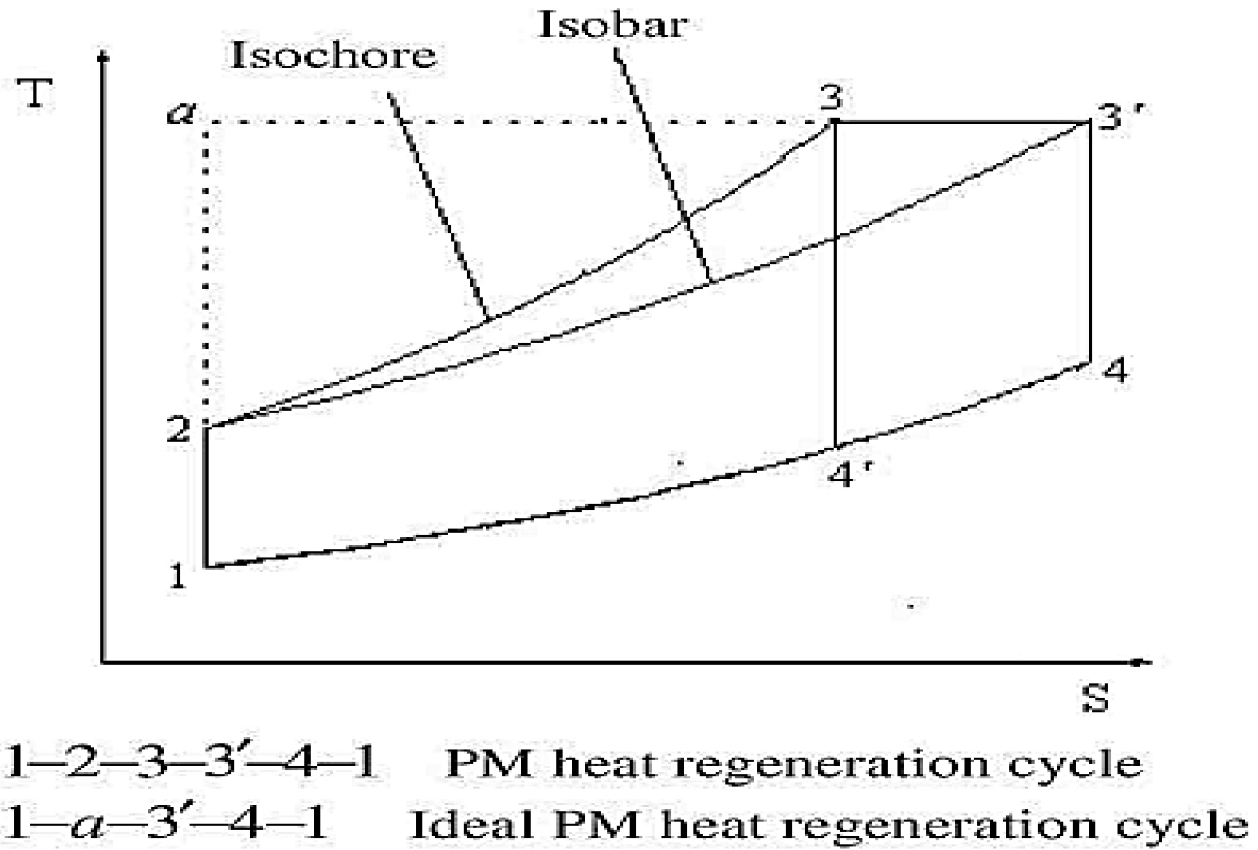
Based on these assumptions, a temperature-entropy diagram of the idealized heat engine cycle with a PM regenerator can be drawn (see
Figure 1). In the PM heat regeneration cycle, process 1–2 represents isentropic compression, which is also present in the Otto and diesel cycles. The heat regeneration process begins at the end of compression when the PM couples with the cylinder. The step proceeds so quickly that it can be modeled as a constant volume process (2–3). Hence the temperature of working fluid remains nearly constant during combustion in the PM, allowing the process to be considered isothermal heating (3–3’). The expansion process is isentropic (3’–4), which is identical to that for the Diesel cycle.
For this system, an energy conservation equation for the gas phase can be written as follows [
14]:
Here, h is the convection coefficient (W/m
2K), ε is a porosity factor, T
g is the porous media gas phase temperature (K), T
S is the porous media solid phase temperature (K), ρ
g is the gas density (kg/m
3), c
p is the specific heat at constant pressure (kJ/kgK), ω is the fuel mole fraction rate (mol/m
3s), u is the gas speed (m/s), and λ’
g is the corrected gas thermal conductivity coefficient (W/mK), which is related to the gas heat conduction coefficient (W/mK), λ
g, as follows [
15]:
where
Here, μ is the fluid viscosity (Pa.s), d
p is the porous diameter (cm), ppc is a regenerator structure specification that can be selected to be 6, 9, or 11, ε is the porosity factor for the porous regenerator, and Pr is the Prandtl number [
15].
The mass conservation equation for the solid phase can be written as follows [
15]:
Here, h
p is the volumetric convection coefficient between the solid and gas phases (W/m
3K), λ
s is the solid thermal conductivity coefficient (W/mK), ρ
s is the solid density (kg/m
3), T
s is the porous solid phase temperature (K), which can be evaluated as follows [
16]:
where L is the regenerator length (m).
The radiation heat flux in the solid phase is simulated using the simple Reynolds model [
17]. Thus,
where σ is the Stephan-Boltzman constant (
), and T
s is the solid temperature (K). With Equations (5)–(7), Equation (4) can be rewritten as follows [
14]:
Here, c
s is the solid specific heat (kJ/kg/K), and λ
eff is the effective heat transfer coefficient in the porous material (W/mK), which can be calculated as follows [
14]:
Here, λe is the porous conduction coefficient (W/mK), and λr is the porous radiation heat transfer coefficient (W/mK).
The mass conservation equation can be written as follows [
18]:
Here, V
i is calculated as [
17]:
The momentum conservation equation can be expressed as follows [
18]:
Here, u
i is the flow velocity in the x direction (m/s), u
j is flow velocity in the y direction (m/s), P is the pressure (Pa), and S
i is the dissipation energy by viscosity (kJ), which can be written as follows [
3]:
The compressed gas in the compression stroke is assumed to behave like an ideal gas. Thus, the following ideal gas equation applies [
17]:
where W is the volume of the compound (m
3). The inlet heat, output work, and PM engine efficiency can be determined respectively as follows [
17]:
Here, z is the compression ratio, φ is the expansion ratio, Q
in is the input heat (kJ), W is output work (kJ) and η is the thermal efficiency. The volumetric efficiency for the PM engine can be expressed as follows [
17]:
where m
air is the mass of air in the cylinder when the inlet valve is closed (kg), ρ
a,i is the inlet air density (kg/m
3), and V
d is the displacement volume (m
3).
The specific fuel consumption is calculated as follows [
17]:
where
is the fuel mass flow rate (kg/s).
4. Results and Discussion
In this investigation, an engine with specific parameters is modeled with SOPHT software (Solver for Principles of Heat Transfer). SOPHT is a computer program package (consisting of solver, models, and example) for the evaluation and solving of heat transfer problems. A moving regenerator is used in this engine. The intake and exhaust valves are the same for both the hot and cold gas flow channels. An important advantage of this regenerator is that it can be made from any material with a high specific heat. An increase in the specific heat gained by modifying the ceramic foam, for example by adding magnesium oxide, can increase the thermal efficiency of the engine by about 1%. This is because of the better flow of fluid in the porosity of the recovery core. The specifications of the engine examined are given in
Table 1.
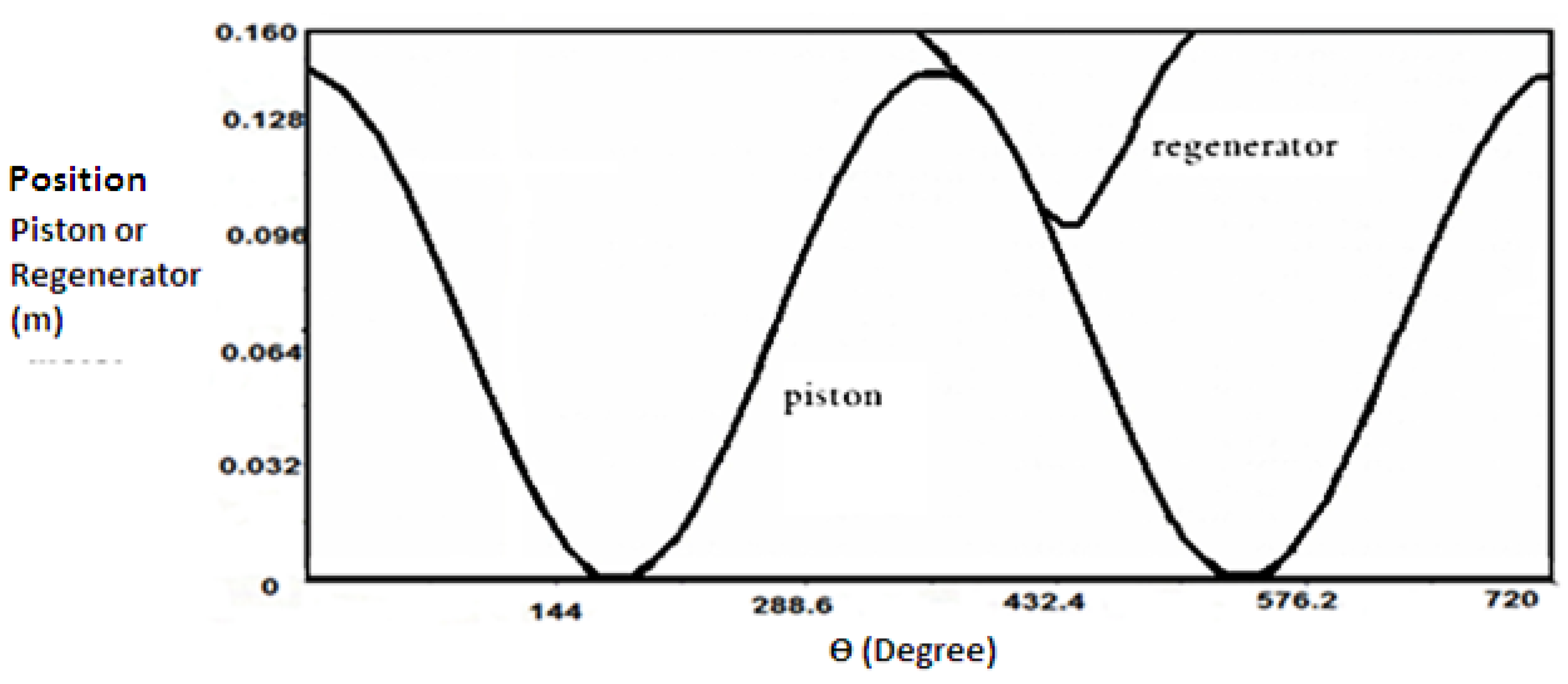
Figure 2 shows the position of the piston and regenerator as a function of crank angle for the complete cycle of a regenerative engine.
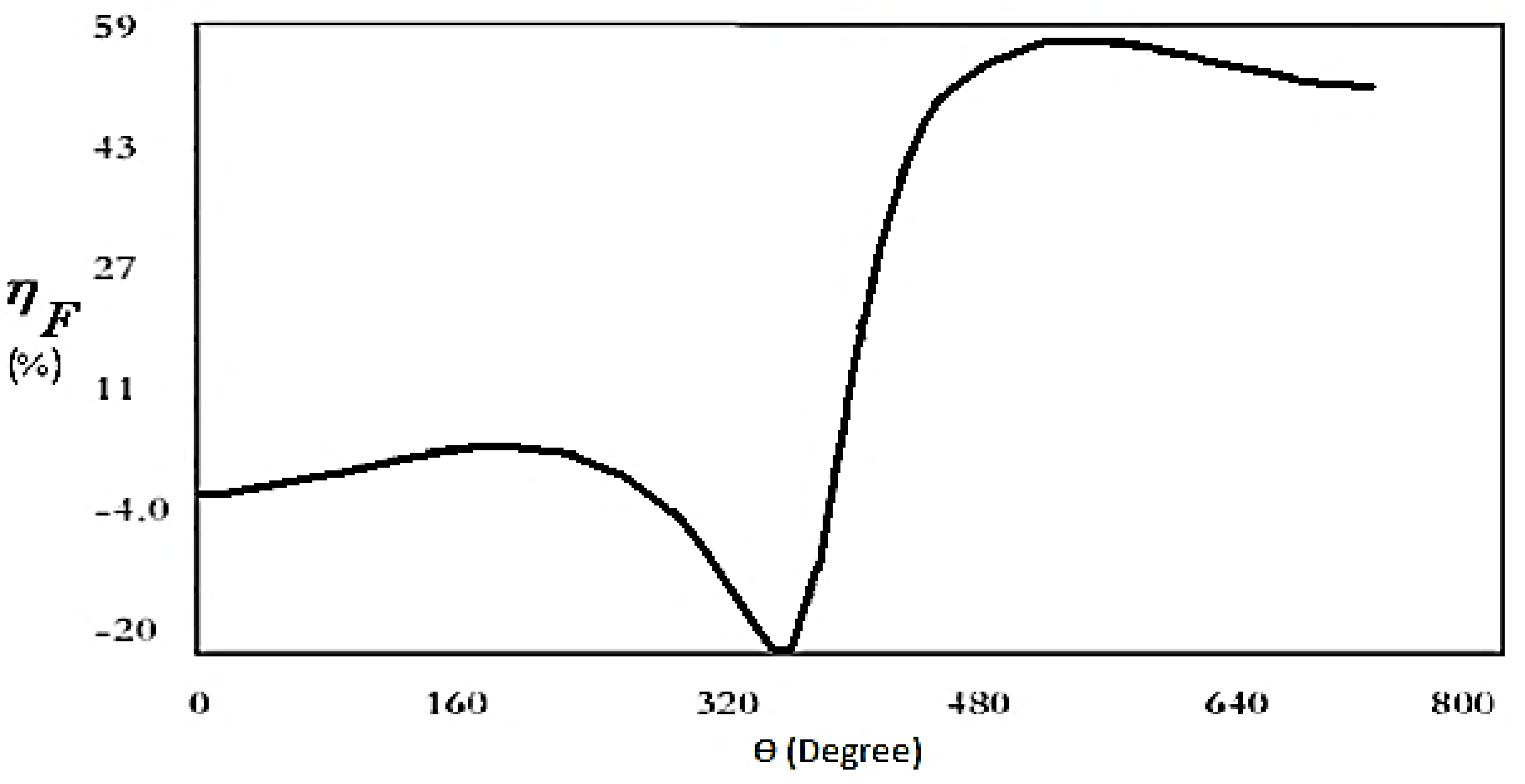
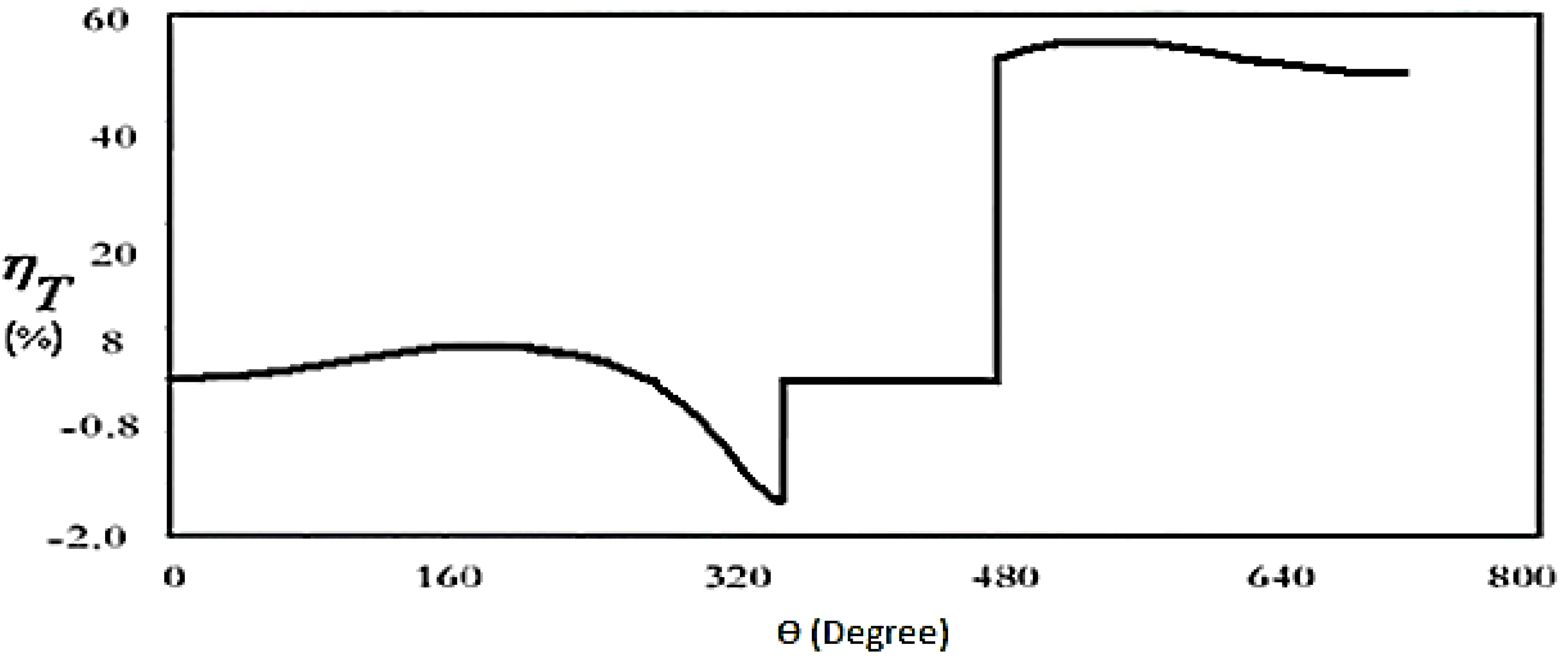
Figure 3,
Figure 4,
Figure 5 and
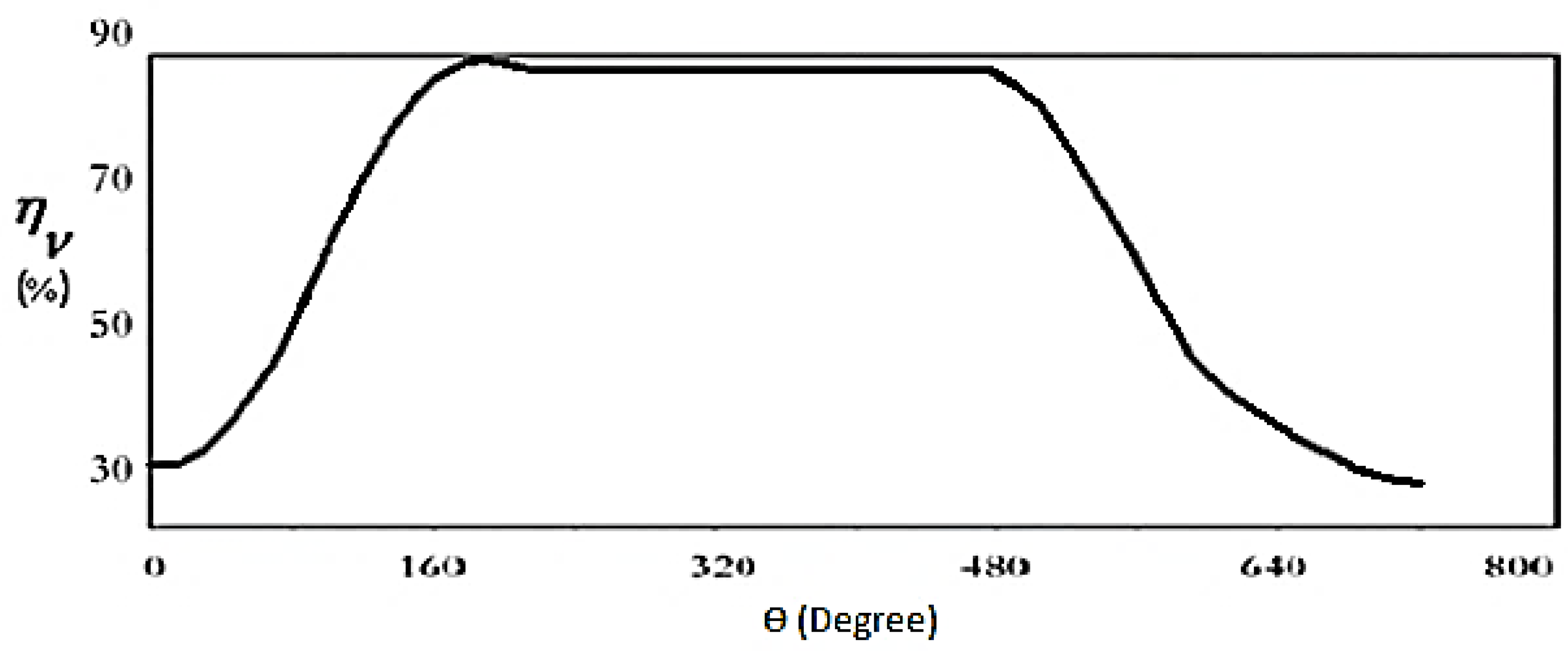
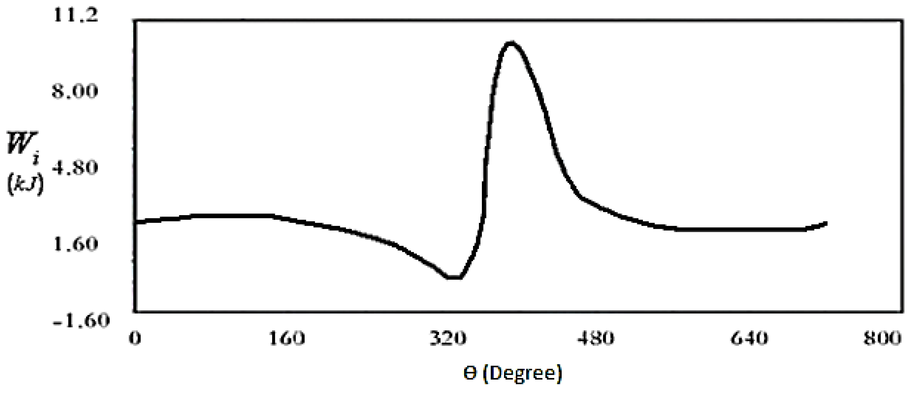
Figure 6 show variations of the fuel, thermal, and volumetric efficiencies and net-work output,
versus crank angle. It can be seen from
Figure 4 and
Figure 5 that when thermal efficiency increases from 43% to 53% with changing crack angle, the volumetric efficiency decreases more gradually, from 94% to 92%.
For the same engine output power, the regenerative engine consumes less fuel than an engine without a regenerator.
Table 2 compares the characteristics of the engine, with and without a porous media regenerator.
By modifying the specifications of an internal combustion engine, the engine can be optimized thermally. But construction procedures and restrictions limit such changes. Increasing the compression ratio causes the maximum pressure to increase proportionally, although it also causes the exhaust gas temperature to decrease. Normally, this is preferred as it tends to reduce burning of the exhaust valve and the resulting increase in temperature at the end of the compression stroke. It also decreases the temperature at the end of the power stroke due to further expansion during the power stroke. So, the thermal efficiency and mean effective pressure are therefore increased as the compression ratio increases. This increase also reduces the dead volume and increases the density of the gas in the cylinder during the combustion process, as well as the short time delay phase. But there are also disadvantages to increasing the compression ratio:
- (1)
The maximum operating pressure rapidly increases with increasing compression ratio because a higher engine mass is required to resist the pressure, and this somewhat offsets the advantage of the increasing thermal efficiency [
13].
- (2)
The abnormal combustion process at high compression ratios results in an increase in noise and potential damage of engine parts. This type of abnormal combustion is known as explosive or detonation combustion [
13].
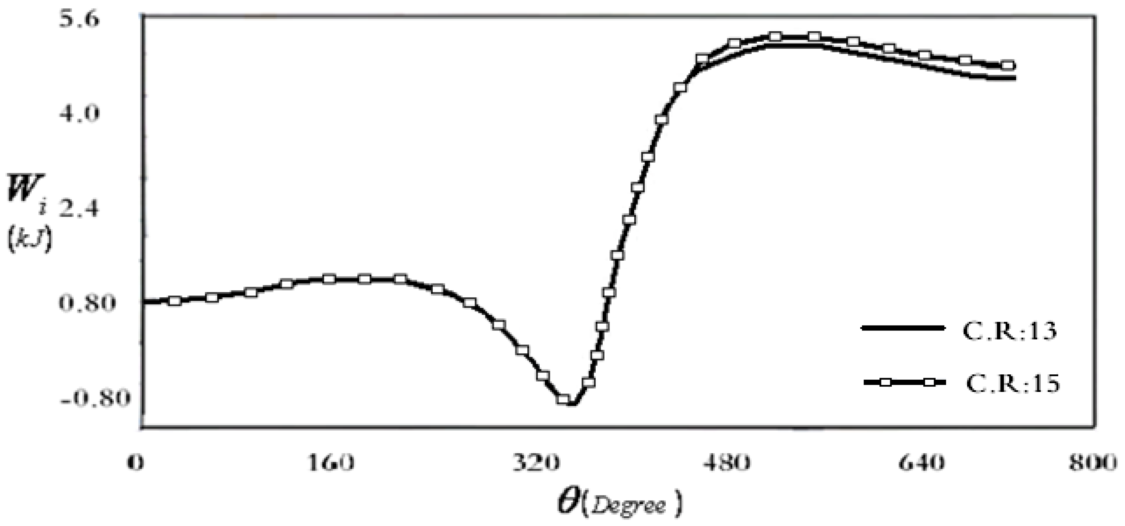
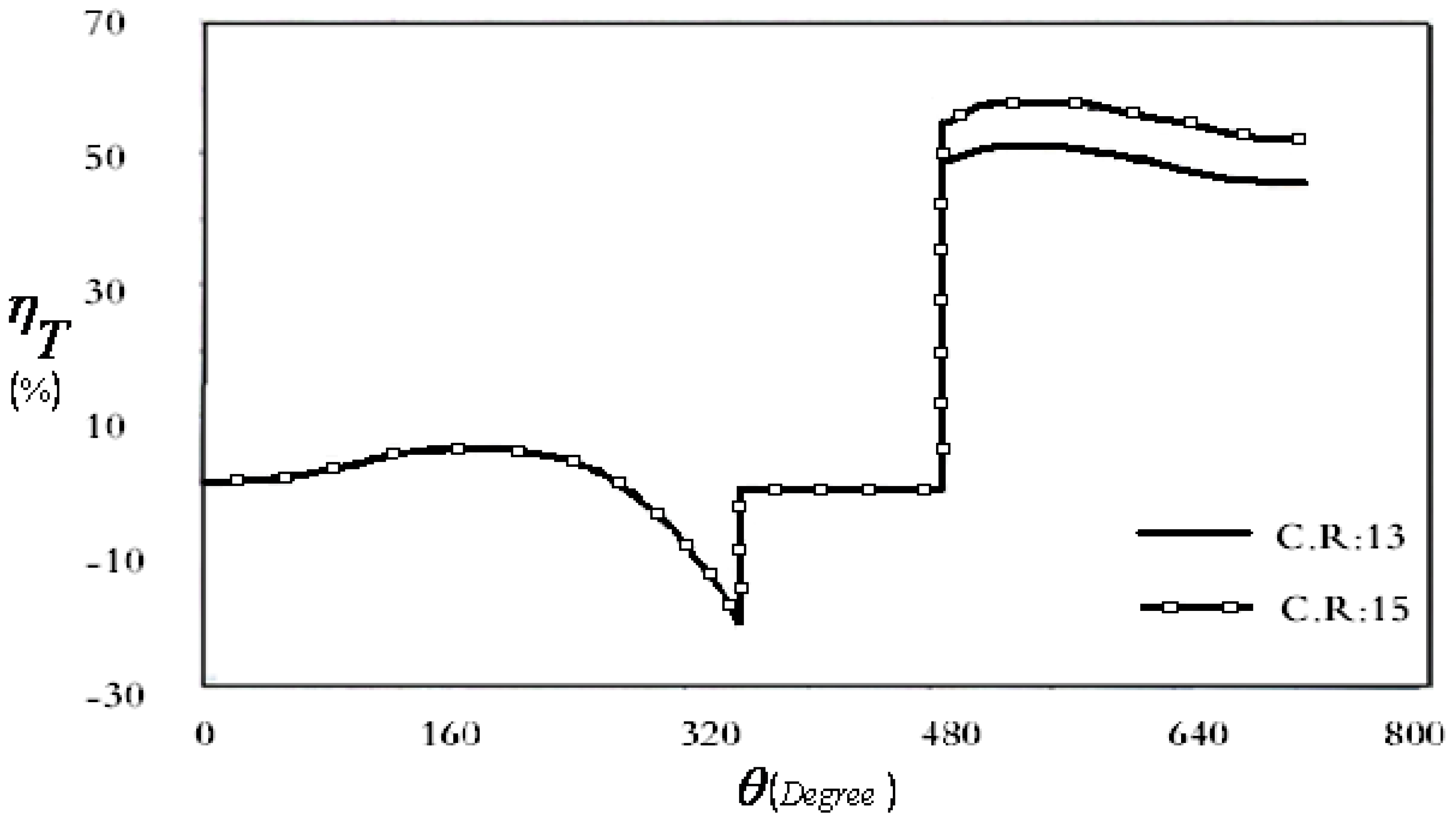
In
Figure 7 and
Figure 8, respectively, variations are shown with crank angle of net-work output and thermal efficiency of an internal combustion engine, with a ceramic foam regenerator. By increasing the compression ratio from 13 to 15, the thermal efficiency increases from 53% to 55% and net output work increases from 4.86 kJ to 4.93 kJ.


