Assessing Rebar Corrosion through the Combination of Nondestructive GPR and IRT Methodologies


1
Defense University Center, Spanish Naval Academy, Plaza de España s/n, 36900 Marín, Spain
2
Applied Geotechnologies Research Group, University of Vigo, School of Mining, Rúa Maxwell s/n, Campus Lagoas-Marcosende, 36310 Vigo, Spain
3
Department of Cartographic and Terrain Engineering, University of Salamanca, Calle Hornos Caleros, 50, 05003 Ávila, Spain
4
PhD Program in Geotechnologies Applied to Construction, Energy and Industry, University of Vigo,36310 Vigo, Spain
*
Author to whom correspondence should be addressed.
Remote Sens. 2019, 11(14), 1705; https://0-doi-org.brum.beds.ac.uk/10.3390/rs11141705
Submission received: 3 June 2019
/
Revised: 12 July 2019
/
Accepted: 16 July 2019
/
Published: 18 July 2019
(This article belongs to the Special Issue Close Range Remote Sensing)
Abstract
:Corrosion is one of the pathologies that most affects the resistance of reinforced concrete. There are numerous ancient structures still in use affected by corrosion that need proper evaluation and remedial treatment for their maintenance. In this sense, there has been an increasing tendency to use nondestructive testing techniques that do not alter the reinforcement elements of such vulnerable structures. This work presents a combined methodology by using ground penetrating radar (GPR) and infrared thermography (IRT) techniques for the detection and evaluation of corrosion. The methodology was applied to the case study of an old construction that belongs to the abandoned military battery of Cabo Udra (Galicia, Spain). The combination of these complementary techniques allowed for the identification of areas with different dielectric and thermal conductivity, as well as different reflection patterns and intensity of the GPR waves. Thus, from the analysis of the GPR signals and IRT images acquired, it was possible to interpret corroded areas and moisture, along with inner damages such as cracking and debonding. These pathologies have a direct effect on the durability and sustentation of a structure, while the knowledge of their existence might be useful for engineers engaged in the design of maintenance works.
1. Introduction
Reinforced concrete structures are the most used element in civil engineering due to the advantages they offer in versatility, resistance, and durability. However, reinforced concrete suffers deterioration caused by different physical, chemical, and mechanical actions to which it is subjected over time. When the concrete presents porosity, for different reasons such as its production, deterioration, aging, etc., an increase in the permeability of the concrete is provoked, creating channels that allow the passage of oxygen, chlorides, or other compounds. Corrosion is one of the main mechanisms that weaken buildings, especially in aggressive environments such as near the coast. This weakening is due to the accumulation of oxides at the interface between steel and concrete, which affects adhesion and generates cracking in the concrete [1]. Corrosion of the concrete reinforcements begins under the presence of oxygen and moisture and can directly influence the reinforced concrete in three possible ways: (1) on the concrete, (2) on the steel, and (3) on the steel–concrete adhesion. In the first phase, the carbonation of the portlandite is produced, generating a layer of calcium carbonate, thicker and harder than the original material. The appearance of this passivation layer exceeds the tensile strength of the concrete and causes cracking in the adjacent concrete to the steel. In the second phase, the depassivation stage, the passive layer of the steel is eroded and there is a lack of section due to pitting corrosion caused by the presence of chlorides. In the last phase, the propagation stage, the accumulation of oxides at the interface of the steel–concrete system affects the adhesion of this system, which generates cracking in the concrete that expands and extends towards the surface and provokes detachment of material.
Once the process starts, the mechanical actions previously mentioned cannot be avoided [2], so the solution to maintain the resistance and durability of the reinforced concrete structure is to have an early detection of corrosion and its effects. However, visual inspection is only effective once the presence of corrosion is evident from the surface of the material [3], so the only actions that may be carried out will be repairing actions instead of preventive. There are different testing methods to evaluate corrosion, which offer different accuracy levels and produce more or less deterioration in the material. However, some of them have an invasive character since they require extracting samples. Within this framework, there are different nondestructive techniques that do not alter the reinforcing structure, such as penetrating liquids, electrochemistry, ultrasound, radiography, acoustic emission, electromagnetic, and infrared methods [4,5]. Among these nondestructive techniques, there are several works in the published literature that have demonstrated the capabilities of the ground penetrating radar (GPR) and infrared thermography (IRT) techniques for the study and evaluation of corrosion [6].
GPR is a geophysical method that allows analyzing the propagation capacity of electromagnetic waves (10 MHz–2.5 GHz) through media with different dielectric constants. The signal is reflected at the interface between two different media with sufficient dielectric contrast. The strength (amplitude) of the reflected fields is proportional to the magnitude of the dielectric constant change. The effectiveness of the method has been proven on the detection and evaluation of corrosion, demonstrating that the characteristics of the reflected signals change depending on the phase of corrosion. Initially, the velocity of propagation of the signal is reduced due to the existence of high water contents [7]. Next, during the expansion phase of iron oxides, the particles released from the oxidation process of the steel rebars occupy the pores of the concrete and cause a volume increase of the steel–concrete system, producing an increase in the amplitude of the reflected signal [8]. During this phase of migration of chlorides and corrosion products, it can also be observed how the frequency spectrum of the reflected signal decreases [9]. However, during the stage in which the section (or diameter) of the bar is reduced, the amplitude of the signal reflected in the bar decreases [10] while increasing the propagation time of the signal to the bar surface and the dielectric properties of the concrete because of the presence of corrosive products in medium. The penetration capacity of the signal and the intensity of reflection will decrease as the chloride and moisture content increase, as well as the concentration of iron oxides, which will expand through the fissures and pores of the structure until signal attenuation or total loss of information [11,12]. This fact is due to the increase in the electrical conductivity of the concrete medium [13]. Therefore, the attenuation of the signal can be studied by attributes of the signal such as the amplitude of reflection, frequency spectrum, velocity, and/or time of propagation of the signal and dielectric constant of the propagation medium. However, they are influenced by the scattering of the signal, produced by the increase in the porosity and cracking of the concrete.
Infrared thermography (IRT) is the technique that calculates the surface temperature of an element, focusing on the measurement of the part of radiation emitted by the body, specifically, of the quantity of radiation which is in the thermal infrared band (8–14 μm). The temperature distribution in the surface of the materials allows the detection and identification of defects and discontinuities, thanks to their different temperatures with regard to the temperature in areas without defects. Provided that superficial temperature comes from the heat inside the object, subsuperficial defects can present a footprint in the surface if they are sufficiently severe or if the ratio depth/size is low; studies [14] have shown that no defects can be detected with IRT techniques over 5 cm depth in reinforced concrete. In addition to temperature, other superficial properties such as emissivity [15] can provoke a discontinuity in the temperature distribution measured, making possible the identification of different materials or superficial defects such as rust when they are in thermal equilibrium with the surroundings because of their different emissivity value. This technique is able to detect corrosion because corroded areas have thermal properties (thermal conductivity and diffusivity) different from that of noncorroded steel rebars [16], in such way that the temperature footprint in the surface where the rebars are located could be different. In the case of cracking, the presence of air in the cracks makes the thermal behavior of the area different from that of the concrete [17]. In the same way, the presence of water affects the thermal behavior of the material, meaning that wet zones present a different thermal footprint than zones without moisture. In relation to this, the detection of corrosion in pipes through IRT is frequently linked to the detection of water in the environment of the pipe as a corrosive agent [18]. Regarding the corrosion of reinforced concrete, laboratory studies have been carried out showing satisfactory results studying the temperature sequences both in the time domain and in the frequency domain of the signal of the radiation in the thermal infrared band [19]. However, most of these studies consist of the application of thermal excitation of different types [20] that allow detecting corroded areas due to their different response for heat transfer when compared to uncorroded steel. The thermal excitation of the element under study limits the applicability of the technique mostly to laboratory conditions, in such way that the methodology should be adapted in the case of outdoor scenarios [21].
The suitability of the combined use of GPR and IRT techniques has been supported by the Federal Highway Administration of the United States for the inspection of reinforced concrete bridges [22] due to their complementary capacity for detection of defects such as corrosion and moisture content at different depths. In addition, the combination of these two nondestructive techniques has been successfully used for the recognition of buried archaeological remains [23], cracks and cavities in pavements [24], and inspection of thermal floors and pipeline configuration [25].
This paper presents a combined GPR and IRT study focused on detecting and evaluating corrosion in reinforced concrete. The GPR method aims to investigate the effects of corrosion and its products on the attributes of the signal (amplitude, dielectric constant, attenuation, etc.), while identifying the existence of internal anomalies such as cracking and detachments, as well as moisture and/or mineral salts content. On the other hand, the IRT technique is ideal to detect the presence of air (cavities, cracking, etc.), because there is less thickness of material and consequently faster heat transfer, and surface defects (moisture, rust, and crust of mineral salts) due to a different emissivity than concrete. Both techniques are applied in this work for the study of a military base with important damage by corrosion, with the objective to evaluate which pathologies are better detected by each technique, and which require the use of both techniques for their specific identification.
2. Materials and Methods
2.1. Case Study
The case study presented in this work is located in the military base named “Battery J2 Cabo Udra” (Bueu, Galicia, in the northwest of Spain). The military batteries are constructions that belonged to a former defensive system of the regime of the Spanish dictatorship, which were designed to protect the Galician coast from possible attacks or incursions by sea.
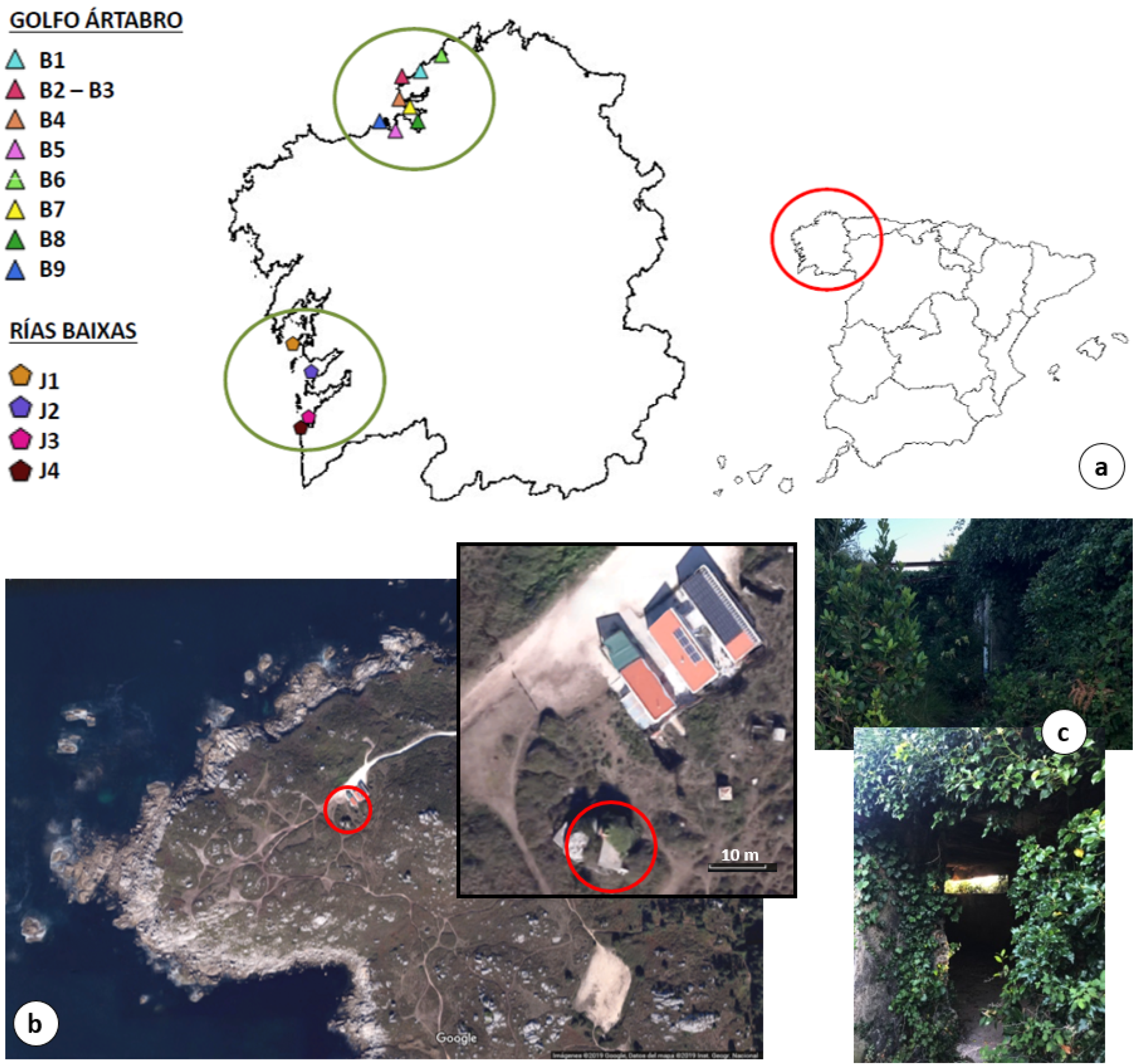
In Galicia, there are two protection zones: Golfo Ártabro and Rías Baixas (Figure 1a). The zone “Golfo Ártabro” was composed of nine batteries aiming to protect the naval base of Ferrol, namely: Monte Campelo (B-1), Cabo Prior (B-2 and B-3), Lobateiras (B-4), Pena Roiba (B-5), O Segaño (B-6), Salgueira (B-7), Monte San Pedro (B-8), and Monticaño (B-9). The second, “Rías Baixas”, was composed of other four batteries placed at the entrance of the estuary: O Grove (J-1) at the entrance of Ría de Arousa, Cabo Udra (J-2) at the entrance of Ría de Pontevedra, and both Monteferro (J-3) and Cabo Silleiro (J-4) at the entrance of Ría de Vigo.
The batteries of the “Rías Baixas” were built in the 1930s. As seen in Figure 1b, the battery under study, J2 Cabo Udra, is located approximately at 200 m from the sea (geographic coordinates ETRS89: Longitude 8°50′3.1214″W and Latitude 42°20′22.0622″N). The structure is composed of brick walls and a 20–30 cm thick reinforced concrete roof. It is 6 m × 4 m long and wide, respectively, which presents an internal configuration of two spaces separated by a narrow wall and an entrance space with no door (see Figure 2c). The battery of Cabo Udra was selected because of the visible deterioration of the structure, including faults in reinforced concrete, such as fissures, cracks, and detachments of the coating, as well as rebar corrosion, most probably caused by carbonation and a higher concentration of chlorides.
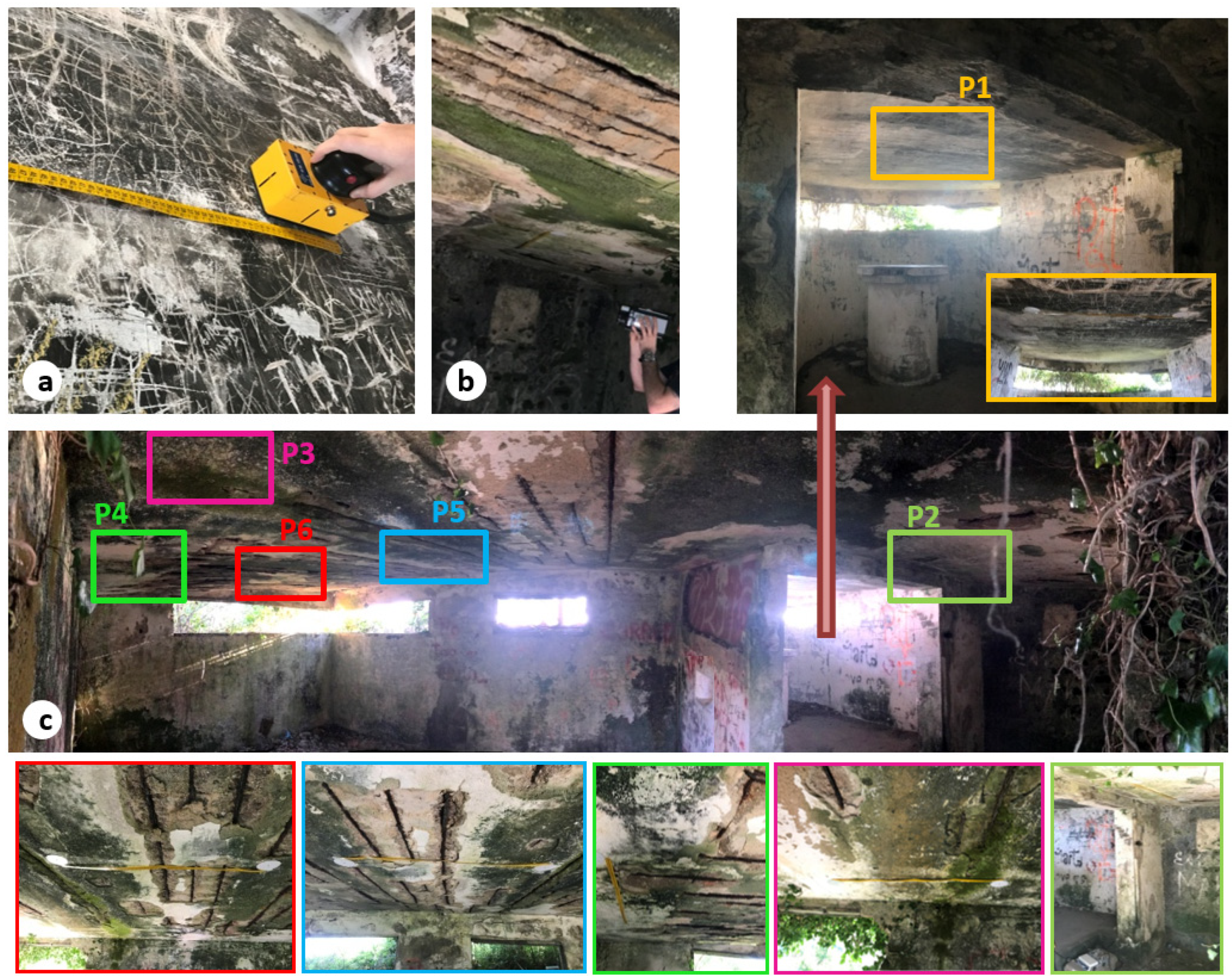
For an exhaustive evaluation of the state of conservation of both reinforced concrete and structure, two complementary nondestructive techniques were combined: GPR and IRT (Figure 2a,b, respectively). As shown in Figure 2c, different measurements were acquired through the inner roof surface of the building. The orange lines show the areas surveyed by both GPR and IRT. Data acquisition was performed in the morning, with the incident radiation of the sun increasing during the survey.
The profiles have been chosen according to the observed pathologies explained in Table 1.
2.2. GPR Data Acquisition and Processing
The GPR study was carried out with a ProEx system from the company MALÅ Geoscience (Malå, Sweden). A high frequency antenna of 2.3 GHz (Figure 2a) was used, with a penetration depth (under ideal conditions) of approximately 40 cm and a spatial resolution of 1–2 cm.
Six profiles were acquired in different areas through the roof of the structure (Figure 2c). The objective was to detect rebar corrosion while evaluating its origins and conditions, as well as to analyze associated pathologies such as cracking, fissures, moisture, etc. The profile lines (data collection) were acquired by moving the antenna perpendicular to the direction of the rebars.
The data acquisition parameters selected were: trace interval distance of 1 cm and total time window of 14 nanoseconds (ns) composed of 292 samples per trace. To measure the profile lengths, and to control the distance between traces, a tape measure was used as a guide (Figure 2a).
Before interpretation, the GPR signals received were processed with ReflexW software (version 8.5.7, Sandmeier geophysical research, Karlsruhe, Germany) [26] using the processing sequence described in Table 2. This filtering aimed to eliminate possible noise or interference with the signal, as well as to amplify the received signal (Gain Function) in order to mitigate possible losses or attenuations. To suppress the continuous component, a vertical or temporal filtering was applied (Subtract-DC-Shift), which allowed obtaining and eliminating from each trace an average value based on the low energy of the last part of the wavelength. A horizontal or spatial filtering (Subtracting average) was also applied to remove horizontal continuous low frequency reflectors, which allowed estimating and removing an average value of all the traces in a time window. Next, a bandpass filter (Butterworth) was used to remove both low- and high-frequency noise in the vertical and horizontal directions.
2.3. IRT Data Acquisition and Processing
The thermographic inspection was performed by a human operator, using a thermographic camera NEC model TH9260 (Figure 2b). This device has an UFPA sensor (Uncooled Focal Plane Array, or uncooled sensor) size 640 × 480 and a field of view of 21.7° in horizontal and 16.4° in vertical. Nominal sensitivity is 0.06 °C. To measure the real temperature accurately, it is necessary to compensate the effects of different sources of radiation that introduce an error in the temperature readings of the termographic camera regarding the real temperature of the body. Some examples are: (i) the reflection of accidental radiation on the object increases the radiation received by the camera from the object, since the camera measures reflected and emitted radiation both as emitted; (ii) all radiation from the object (either emitted or reflected) is absorbed by the atmosphere, in such way that there is a small reduction on the temperature measured by the camera regarding the real temperature of the object. In addition, it is necessary to introduce the variability of the surfaces under study in the computation of temperature, which is done by means of the emissivity parameter. Emissivity stands for the ratio of radiation emitted by a body regarding the total radiation exiting from it. Thus, for the same ambient conditions, the thermographic camera measures different temperature values for the different objects under study, if their surfaces are different. However, the emissivity accounts for the condition of the superficial layer of the object under study, and can be considered as uniform in situations like the study area, where all the structure is made from the same material. For this reason, the thermal images are an image of apparent temperature, which is a noncompensated reading, where the emissivity is set to 1.0 and the distance to 0 meters in such way that the measurement contains all the radiation incident on the instrument. The apparent temperature allows one to carry out a qualitative technique, analyzing thermal patterns and anomalies in the image. The apparent temperature approach was chosen to enable the identification of pathologies such as mineral salts, rust, and biological activity as areas with different temperature even in homogeneus temperature conditions, due to their different emmissivity.
The study area was at an ambient temperature of 16 °C, with a relative humidity close to 70%. Regarding the distance of 1 meter between the camera and the study profile, it was necessary to acquire two to three thermal images per profile, with a horizontal overlap of 10–30%. This overlap is required for the integration of each profile-image in one unique image for a complete visualization of each profile, so that missing defects appearing partially in different images is avoided: overlapping areas allow for the identification of common features between images. Two reflective targets have been placed at the ends of the tape measure to facilitate the identification of corresponding points between the thermal images, as well as the association between the thermal images and the GPR profiles.
The thermographic study was made with a two-fold approach: on one hand, the temperature profile of each image was studied in order to identify the presence of pathologies based on the temperature anomaly they imply. On the other hand, each image was subjected to a filtering process, as in [27], for the delimitation of the pathologies in the image, focusing on their two dimensions. This process is based on two assumptions:
Temperature in the moist area is either lower or higher than temperature in the surroundings, due to the higher thermal inertia of water that slows down the processes of heating and cooling in comparison with the same processes in dry materials.
A thermal image with a pathology presents a pseudobimodal temperature distribution (Figure 3), which is a combination between a Gaussian and a bimodal Gaussian distribution. This temperature distribution presents two peaks, one corresponding to the “healthy” area, and one generated by the “pathology” area.
Taking these assumptions into account, a self-developed code is applied to the images for the automatic detection and delimitation of moisture areas. The code evaluates the temperature distribution of each images, analyzing the number and position of the peaks. Then, the overlapping point between Gaussian curves is calculated, and the temperature value of the point is established as threshold between “healthy” and “pathology” areas. The threshold allows the definition of pixels as “contours” of the pathology area, which are consequently highlighted for the pathology delimitation.
3. Results and Discussion
3.1. GPR Imaging and Data Interpretation
The condition of rebars and concrete are defined by the analysis of the signals received, the velocity of signal propagation and other properties or attributes of the signals including amplitude, attenuation, and signal polarity. The purpose was to identify and classify deteriorated areas, namely: concrete detachment or debonding, moisture, rust, or high mineral salts content, as well as voids beneath detached concrete.
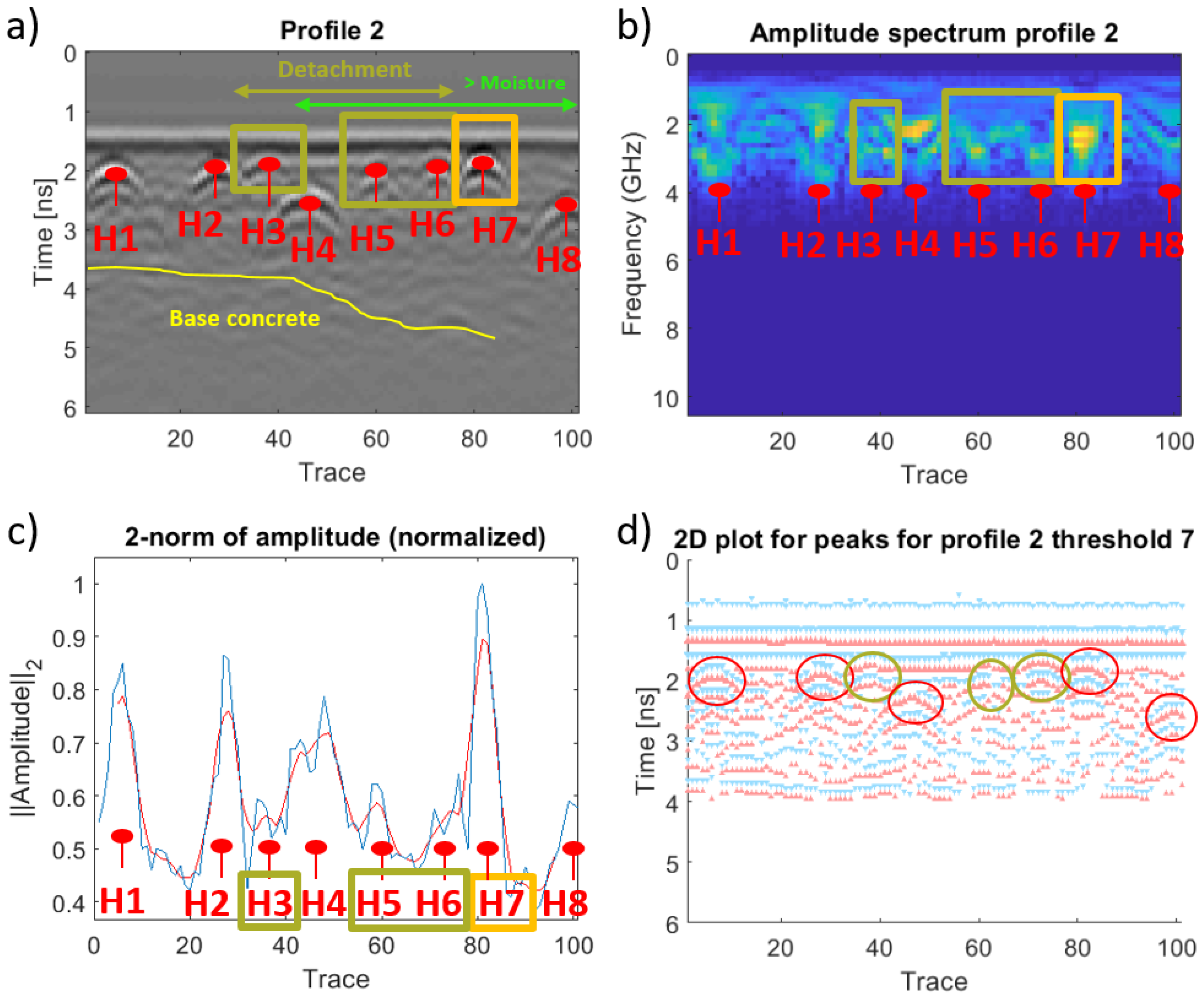
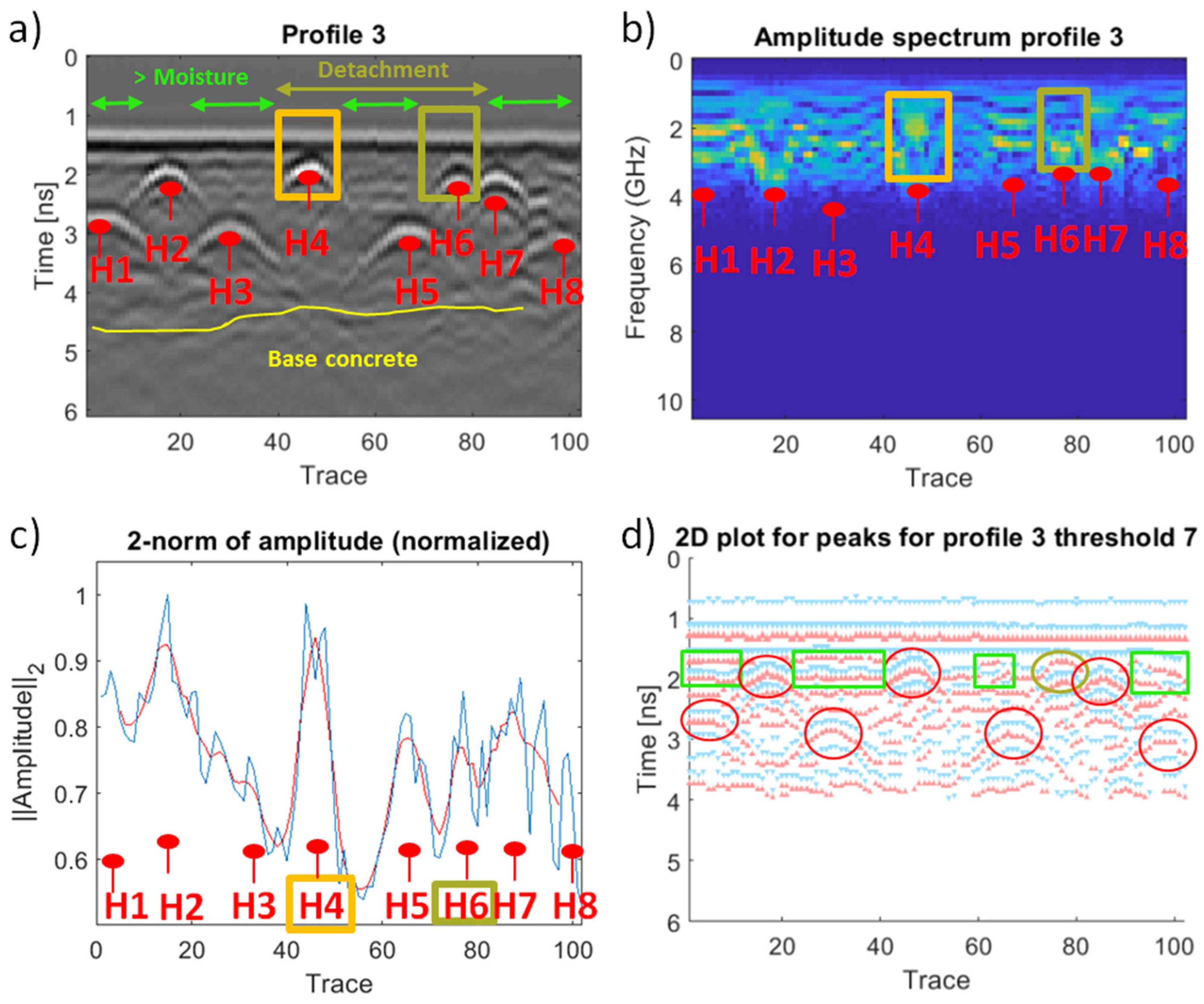
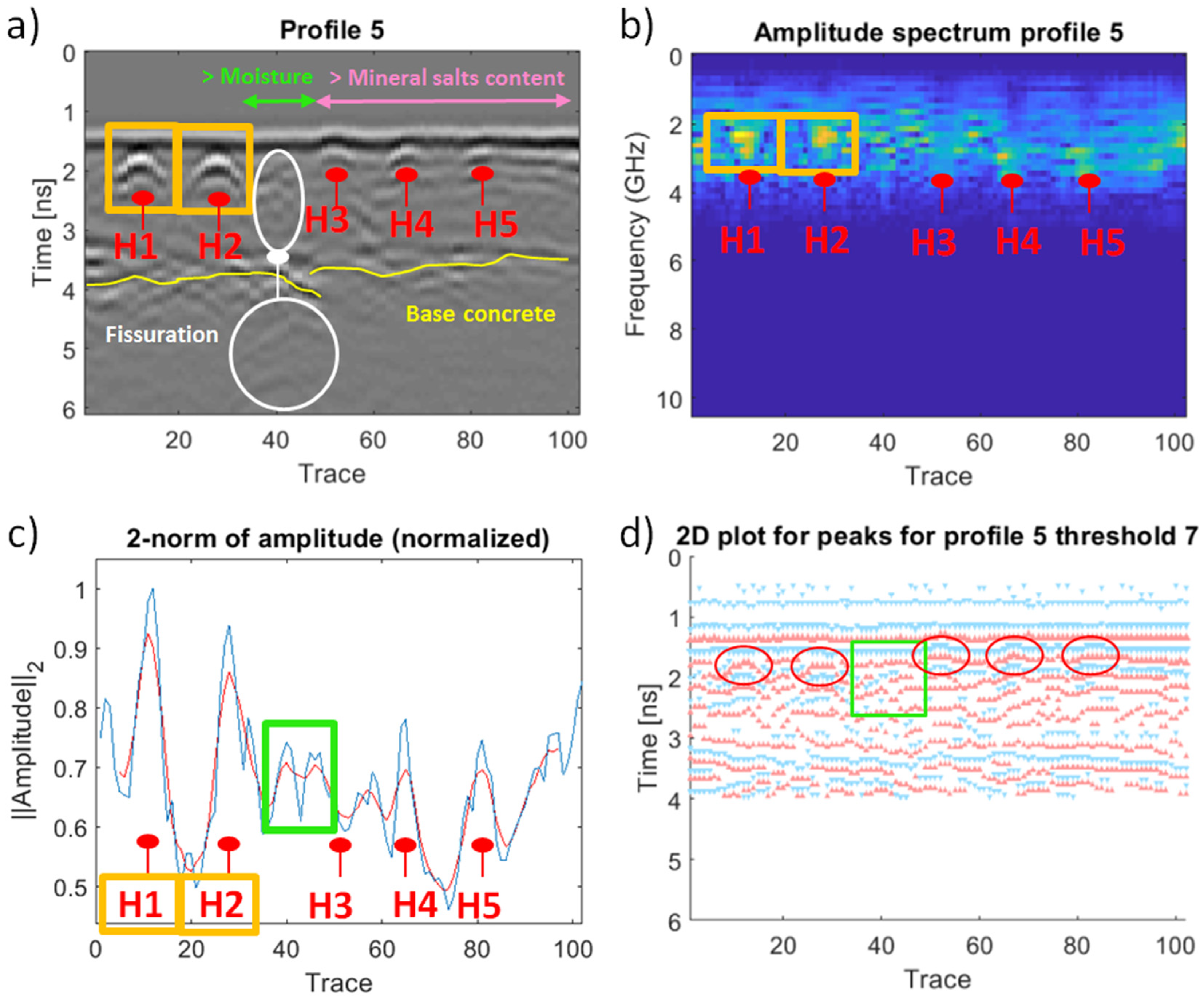
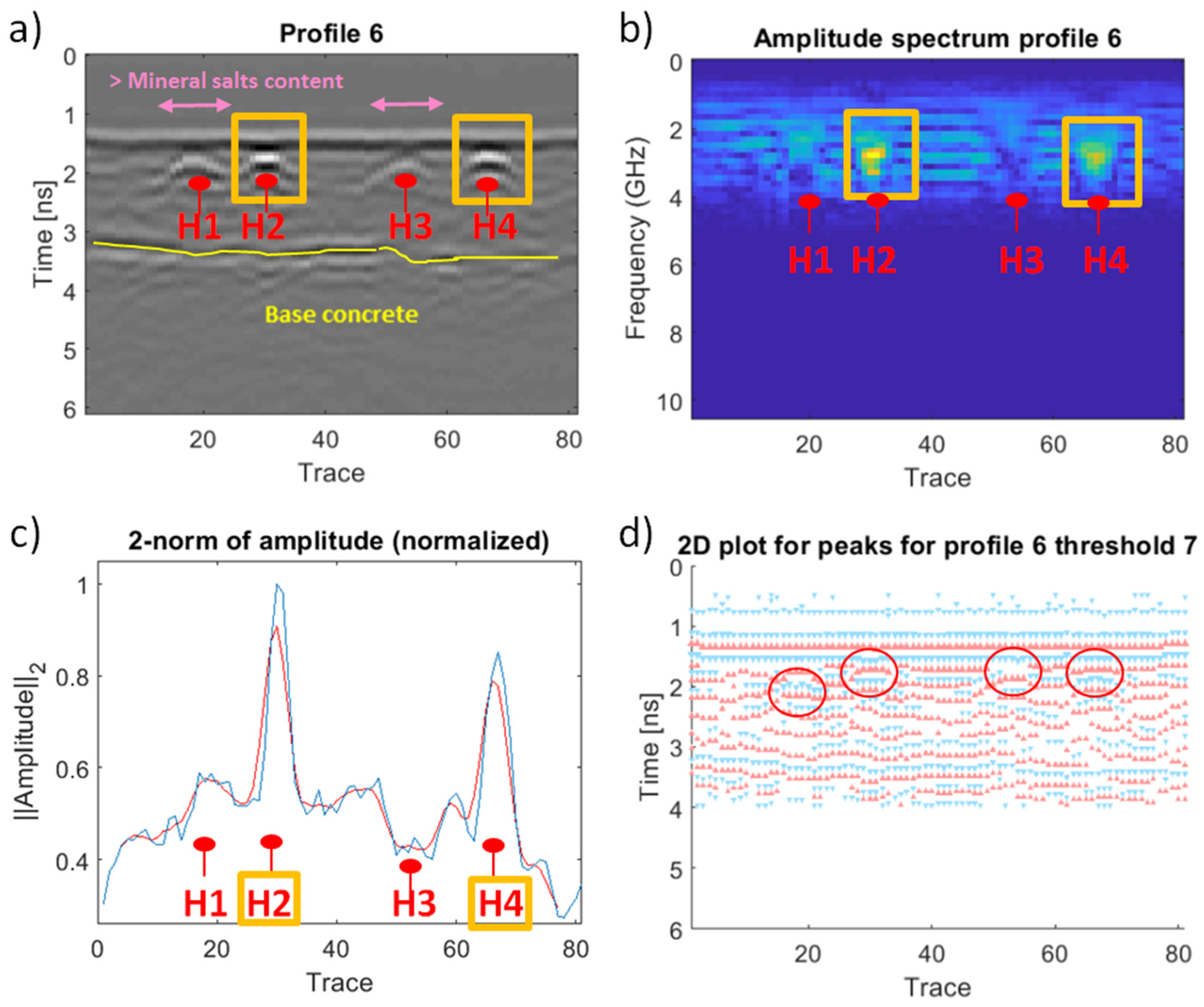
Several different types of graphics are shown in the following figures. Though the total time window is near 13 ns, we select just the first 128 samples of each trace, around 6 ns, where all the relevant features are placed. Figure 4a shows an example of a trace, where the 0 to 6 ns range has been highlighted in red. The table in Figure 4b provides information about some of the peaks detected in the selected range using the findpeaks function in Matlab. For each peak, its travel-time distance, as well as the position and value of the particular peak sample are shown. These peaks are also marked in green in Figure 4a. Figure 5, Figure 6, Figure 7, Figure 8, Figure 9 and Figure 10 show, for each of the six GPR profiles considered: (a) a 2D grayscale radargram, (b) a colorscale 2D map of the one-sided amplitude spectrum of the radargram, (c) the 2-norm of the amplitude (normalized), and d) a 2D plot of the most relevant amplitude peaks in a profile (either negative, depicted in blue, or positive, in red) detected using the findpeaks function in Matlab.
In order to obtain these graphics, we take as input the processed GPR data (Table 2), except for the graphic d, in which the data was only corrected for continuous component (DC). For the 2-norm of the amplitude graphic, an N-dimensional vector with the 2-norm of each of the N traces in a profile is computed. Then, this vector is normalized, dividing by its maximum, and the result is depicted (in blue). A moving average with window size N/20 is also depicted (in red). In order to select the most relevant peaks to be plotted in graphic (d) we use a thresholding strategy: the log2 of the absolute value of each peak is computed and when this value is greater or equal to a predefined threshold, the peak is depicted in the graph. We use seven as the threshold value in all the figures, as we empirically found that it provides a good tradeoff between the number of peaks represented and their relevance.
To facilitate the rebar identification, during the GPR data acquisition, the antenna was moved perpendicular to the longitudinal axis of the rebar. Thus, the cross section of such rebar is a circle that provides a hyperbolic reflection in the radargram [28].
Table 3 presents the amplitude values and travel-time distances computed with the findpeaks function for the most relevant peaks associated with the hyperbolic reflections obtained by each GPR profile line.
Figure 5 shows the GPR data obtained for profile 1, the nondamage area, highlighting the five hyperbolic reflections (H1 to H5) produced by the rebars located in such area. It is easily observed that rebars are characterized by prominent hyperbolic reflections with a stronger amplitude spectrum (Figure 5c), as well as its positive signal polarity (see Figure 5d and Table 3). Moreover, the reflections from the rebars and the base concrete are seen to be at a time-depth of ~2.25 ns and 4 ns, respectively.
Regarding profile 2, the hyperbolic reflection number 7 presents a stronger amplitude spectrum (Figure 6b) and higher amplitude value (Table 3), which is most certainly produced because it is a nearly open-air rebar (see Table 1), at a travel-time distance of 1.86 ns. On the other hand, the reflections number 3, 5, and 6, at a travel-time distance of ~1.9 ns, present reverse polarity (Figure 6d and Table 3) that could be associated to the presence of voids beneath detached concrete (Table 1). Finally, the rebar reflections number 4 and 8 are registered at larger travel-time distances, 2.33 ns and 2.57 ns, respectively, which is produced by an increase on the dielectric constant in the upper media due to a higher level of moisture [29]. It is important to mention here that when a rebar is corroded, corrosion infects the surrounding concrete, causing a severe change in the actual dielectric properties of the upper media of concrete. This leads to a decrease on the propagation velocity in the upper media. Thus, it is possible to observe how the reflection produced by the base concrete presents an increase on the travel-time distances registered, which extends from rebar 4 to rebar 8.
Regarding profile 3, there is a nearly open-air rebar (H4), at a travel-time distance of 1.9 ns, showing a stronger amplitude spectrum (Figure 7b). Observing Table 1, this area presents severe concrete detachment and signs of moisture corresponding to lawn green rectangles in Figure 7d, while showing negative signal polarity (Figure 7d). As a consequence, the reflections produced by rebars 1, 3, 5, and 8 present lower amplitude values, or attenuation, (Table 3) and larger travel-time distances (2.76, 2.90, 3.00, and 3.09 ns, respectively). Furthermore, the hyperbolic reflection H7 recorded at trace 77 (2.05 ns) shows a reverse polarity (Figure 7d and Table 3), most certainly produced by the presence of a void or debonding in the concrete. Finally, it is possible to note an increase in the travel-time distances registered for the base concrete reflection, in comparison with profile 1, due to the higher moisture shown in profile 3.
In profile 4, there is a general increase in the travel-time distance produced by the detachment and moisture content externally observed (see Table 1). Figure 8d displays three different zones showing a complex reflections pattern with negative signal polarity (lawn green rectangles), which are most probably caused by a higher water content in these areas. Thus, as shown in Table 3, the reflections produced by rebars 2 (H2) and 4 (H4) present lower amplitude values in comparison with rebar 5 (H5), which is the one presenting a nondamage behavior. Moreover, the reflections H2 and H4 registered larger travel-time distances (3.14 and 3.48 ns, respectively) than H5 (2.33 ns). Observing the reflection generated from the base concrete, the travel-time distances are larger (~ 4.5 ns) from H1 to H4, and lower (~ 4.0 ns) in the H5 area. Finally, concrete debonding, and subsequent spalling or fissuration, was identified over rebars 1 (H1) and 3 (H3).
Concerning profile 5, the hyperbolic reflections produced by rebars 1 (H1) and 2 (H2) show more prominent reflections (Figure 9a) and stronger amplitude spectrum (Figure 9b) corresponding to concrete detachment and nearly open-air rebars (1.81 and 1.86 ns, respectively). On the contrary, despite rebars 3 (H3), 4 (H4), and 5 (H5) being superficial open-air rebars, they present more attenuated signal reflections (see amplitude values in Table 3) and lower amplitude spectra, which most probably indicates the presence of corroded rebars with a significant loss of section (mass loss) produced by a higher content of mineral salts in this area. In addition, severe concrete spalling or fissuration is observed before this corroded area (Figure 9a,b).
Finally, profile 6 shows prominent reflections (Figure 10c) and a stronger amplitude spectrum (Figure 10b) for the open-air rebars 2 (H2) and 4 (H4); whereas rebars 1 (H1) and 3 (H3) present more attenuated signal reflections (see amplitude values in Table 3) and lower amplitude spectra, which could be connected with a higher mineral salts content in this area (see Table 1) and the loss of section typically associated to corroded rebars.
3.2. IRT Data Interpretation
Temperatures along the roof of the military battery vary between 18 and 24 °C, according to the ambient temperature during the survey, and the heating provoked by the direct radiation of the sun on the outer surface of the wall under study.
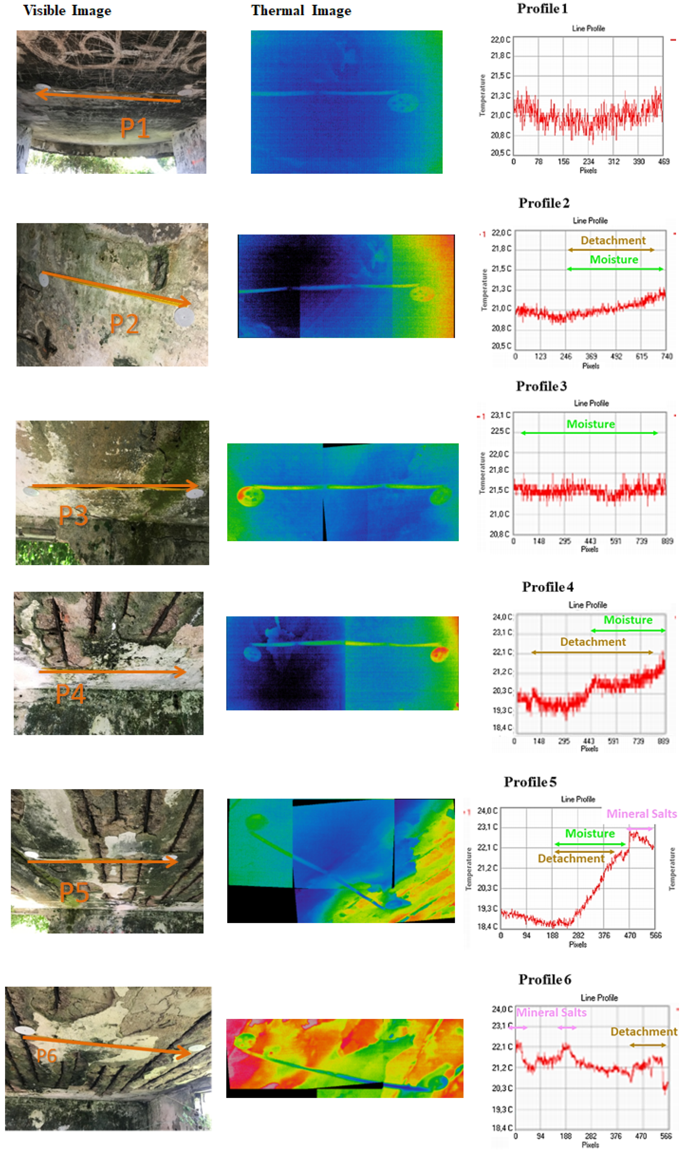
In order to determine the presence of pathologies in the areas under study, a temperature study was performed, based on the temperature distribution of the profile lines measured with the GPR antenna (Figure 11). This way, a direct correlation between temperature and GPR signal attributes can be made.
In this case, the thermal print of corroded bars on the surface of the roof is covered by the effect of moisture, rust, and delaminations on the most superficial layer of the roof. Profiles 1 and 3 show constant temperature with different absolute values. This implies that either there is no anomaly, or the whole image covers an area with pathology. Correlation with the GPR interpretation (Figure 5 and Figure 7, respectively), and focusing on the temperature difference, the temperature value of profile 1 (21.0 °C) corresponds to the “healthy” material, while the temperature value of profile 3 (21.5 °C) belongs to continuous moisture. That is, the area covered by profile 3 is completely moist. This temperature difference in moist materials is caused by the higher thermal inertia of water, which slows down the cooling process occurring during the night.
The temperature evolution of profile 2 presents a continuous temperature increase from the first third of the profile. This increase corresponds to detachment in the area, plus the effect of moisture. Detachments appear as an area with higher temperature due to the reduced thickness of the roof in the area where the material is lost and due to the presence of air between the roof and the material pending.
Profile 4 presents two different pathologies, whose effects are more important and visible in different areas. At the beginning, the temperature increase after a sudden temperature reduction corresponds to the presence of detachment, while the last part of the profile presents a deeper temperature increase, caused by the addition of the effect of moisture. This coexistence of pathologies can lead to the correlation of moisture with the detachment in such way that the first is unequivocally the cause of the second.
The temperature evolution in profile 5 also presents the combined effect of detachment and moisture, appearing as a continuous and steep temperature increase. In addition, there is a sudden temperature peak at the end of the profile that corresponds with the presence of mineral salts. These last pathologies are distinguishable due to their high reflectivity (low emissivity), that provokes a temperature peak without a constant evolution, neither before nor after its presence.
The same happens in profile 6, where mineral salts are found at two positions of the profile. In addition, at the end of the profile, the presence of detachment can be detected with a temperature increase, with a more continuous and smooth transition from the healthy parts than in the case of the mineral salts.
Further analysis is performed for the pathologies detected, with the aim at delimiting the area affected. For the study, the overlapping point between the two Gaussian distributions of each image is calculated and used as threshold for the classification of pixels as “pathology” or “nonpathology”. Results obtained are shown in Table 4. According to the results obtained, the self-developed code for the delimitation of pathologies is very useful for the definition of the most important pathology, in terms of extension. Thus, it is not possible to automatically delimit smaller defects such as mineral salts. The code works with the temperature values and provides the result of the area of the pathology but does not modify the thermal image.
3.3. Joint Interpretation of Both Techniques
One of the main objectives of this study was to analyze the complementary combination of both GPR and IRT nondestructive methods. Thus, the results obtained with both techniques were compared in terms of their capabilities to identify anomalies or pathologies that exist in the profile lines under study (Table 1).
Observing the real image of profile 2 in Table 1, this zone presents two main areas with fissuration, moisture, loss of material, and visible bars. In the corresponding radargram (Figure 6), eight hyperbolic reflections were identified: five were interpreted as bars while the other three were interpreted as voids beneath detached concrete, the latter interpreted via reverse polarity. Rebar 4 (at the middle of the radargram) and rebar 8 (at the end of the radargram) were registered at larger travel-time distances most certainly due to higher moisture or corrosion products in such areas that decrease the velocity of propagation of the signal. In the thermographic image, there is variation in the temperature values in the central zone, delimiting the area of detachment and moisture (Table 4) because they offered discordant values with the environment of 0.3 °C.
The GPR data produced by profile 3 reveals higher moisture along this entire zone, as well as a central area showing concrete detachment (Figure 7). The thermal image shows only the presence of moisture represented with higher temperature (0.5 °C more than the healthy area in profile 1). The lack of identification of detachment in profile 3 with IRT is because the footprint of moisture is more important and covers the identification of any other present pathology.
In profile 4, the thermal image shows the combined effect of detachment (in all the image) with additional moisture (in the second half of the image). The GPR data reveals severe detachment over rebars 1 and 3 (Figure 8), while the other hyperbolic reflections were registered at larger travel-time distances, indicating higher moisture.
Regarding profile 5, the real image in Table 1 shows a zone divided into two different areas: the left part presents higher moisture and rust, while the right part presents loss of material and visible rebars. The study of the thermal image indicates that the temperature difference between the left and the right part is 1.5 °C, with much lower temperature on the left, because it has greater thickness of material. This implies the presence of detachment and moisture on the left side of the image. In addition, a sudden temperature peak towards the end of the profile can be assigned to the presence of mineral salts, with high reflectivity that provokes an apparent immediate temperature increase. With respect to the GPR data, although the left part of the profile presents material, the rebars appear closer to the surface because of detachment, whereas the reflections produced by the visible rebars show severe signal attenuation, instead of the expected higher amplitude, which could be caused by the higher conductivity of salt solutions.
In profile 6, there is a central island of material surrounded by severe detachments (see Table 1). At the beginning of the thermographic profile (Figure 11), the presence of two sudden temperature peaks reveals the presence of two accumulations of mineral salts. These zones appear at 1 °C more than the rest. Observing the GPR data in Figure 10, these zones correspond with hyperbolas 1 and 3, showing apparent signal attenuation due to the presence of mineral salts.
Table 5 presents a summary of the pathologies found in the study and the effect they produce on the GPR signal and the thermographic images.
4. Conclusions
The analysis of the GPR signals allowed us to identify corroded rebars, detachment, or fissuration and voids beneath detached concrete, as well as to define areas having higher moisture and/or mineral salts content. Thus, open-air rebars (corroded material) show more prominent reflections and stronger amplitude spectrum than embedded rebars (uncorroded material). In the case of voids in concrete, the hyperbolic reflections obtained present lower amplitude spectra and reverse polarity in comparison with the hyperbolic reflections produced by rebars. Nonvisible rebars showing hyperbolic reflections near the surface and higher amplitude spectra seems to indicate detachment in concrete, and the travel-time distance decreases because the velocity of propagation of the signal in the air is faster. A higher velocity of propagation implies a lower dielectric constant in the medium. Additional, signal attenuation can be associated to delamination or detached concrete. This is because the dielectric contrast between media is much larger in concrete–steel interfaces than in concrete–air interfaces. A higher dielectric contrast means a higher strength of signal reflection. On the other hand, an increase of the travel-time distance suggests signs of moisture, which is caused by a lower velocity of propagation or higher dielectric constant in the medium. The presence of moisture is also interpretable due to the signal scattering and the higher amplitude in the surrounding media. It is important to mention here that the concrete–water interface has higher dielectric contrast than the concrete–air interface and, subsequently, stronger reflection. As a consequence, the deeper reflection produced by rebars presents more attenuated signal reflection. Finally, it was also possible to differentiate the effects of the mineral salts on the GPR signals. Salts have high conductivity which produces severe absorption of the signals. Zones with a significant content of mineral salts can be easily recognized by much lower amplitude spectra and very smooth reflections.
The IRT shows the areas with detachment of material, moisture, and biological activity, from the interpretation of their thermal fingerprint and the temperature profiles, as well as identifying the transition zones between different pathologies. In addition, the study of the temperature distribution allows the delimitation of areas with pathologies, especially those with big extensions, such as moisture and detachment. The apparent temperature allows identifying anomalies in the images, associating low anomalous values to areas with moisture and detachment, and very high values to efflorescence. In the first case, the reason is that the areas that accumulate water inside have more thermal inertia; in the second case, the cause of the temperature increase is that the concentration of salts presents lower emissivity (higher reflectivity) than the concrete with and without moisture, which makes the efflorescence appear at a higher temperature. The detection of the salt concentration pathology is possible due to the performance of the inspection with apparent temperatures instead of emissivity-corrected temperatures, since the difference of efflorescence with the surroundings is mainly due to emissivity and not to a lack of thermal equilibrium. The radiation of the sun on the opposite surface is more direct as it approaches noon than early in the morning, so the areas where there is detachment of material and less thickness are at higher temperatures for the day and are cooler at night. The profiles that are close to a window have temperatures closer to the outside of the construction than those that are more inside the battery, since air renewal occurs more frequently, not allowing the accumulation of cold air and the consequent cooling of the walls.
The joint interpretation of both GPR and IRT data confirmed the independent interpretations provided, which allowed for a better understanding of the behavior of the GPR signals (e.g., with IRT it was possible to confirm when the signal scattering was produced by delamination or when the signal attenuation was produced by higher moisture or mineral salts content).
Regarding the GPR data processing and interpretation, follow-up works include the use of GPR phase analysis techniques [30] as an additional tool for the identification of cavities in corroded concrete. We also plan to explore the use of time-series clustering algorithms [31] to analyze profile traces in order to automate the identification and categorization of key features (such as cavities, rebars, and moist areas).
The main efforts in the IRT data processing will focus on the improvement of the self-developed methodology for the delimitation of more than one pathology in each image. For this, the assumption of pseudobimodal temperature distribution will have to be changed. In addition, current efforts are being made on the design of a methodology based on SVM (support-vector machine) for the automatic determination of moisture and other similar pathologies, such as thermal bridges [32].
The combination of both techniques will be further exploited for the quantitative characterization of the pathologies detected, in such way that their depth and extension can be determined.
Author Contributions
M.S. and S.L. conceived and designed this study. M.S. and N.F. acquired, processed and interpreted the GPR data. S.L. and I.G. acquired, processed and interpreted the IRT data. M.S., S.L., N.F. and I.G. wrote the paper.
Acknowledgments
The authors are grateful to Vega Pérez-Gracia for inviting them to submit this paper to the Remote Sensing Special Issue “Close Range Remote Sensing”. This work has been partially supported by the Spanish Ministry of Science, Innovation and Universities through the project Ref. RTI2018-095893-B-C21. The Applied Geotechnologies Research Group of the University of Vigo and TIDOP Research Group on the University of Salamanca are acknowledged for all the human and facilities provided that has made this research possible. Authors would also like to thank Iberdrola S.L. and University of Salamanca for the funding provided through Cátedra Iberdrola VIII Centenary.
Conflicts of Interest
The authors declare no conflict of interest.
References
- Ahmad, S. Reinforcement corrosion in concrete structures, its monitoring and service life prediction. Cem. Concr. Compos. 2003, 25, 459–471. [Google Scholar] [CrossRef]
- Ma, F.Y. Corrosive effects of chlorides on metals. Pitting Corros. 2012, 294, 139–178. [Google Scholar] [CrossRef]
- Alsharqawi, M.; Abu, S.; Zayed, T. Integrated condition rating and forecasting method for bridge decks using Visual Inspection and Ground Penetrating Radar. Autom. Constr. 2018, 89, 135–145. [Google Scholar] [CrossRef]
- Assouli, B.; Simescu, F.; Debicki, G.; Idrissi, H. Detection and identification of concrete cracking during corrosión of reinforced concrete by acoustic emission coupled to the electrochemical techniques. NDTE Int. 2005, 38, 682–689. [Google Scholar] [CrossRef]
- Sharma, A.; Sharma, S.; Sharma, S.; Mukherjee, A. Monitoring invisible corrosion in concrete using a combination of wave propagation techniques. Cem. Concr. Compos. 2018, 90, 89–99. [Google Scholar] [CrossRef]
- Zaki, A.; Chai, H.K.; Aggelis, D.G.; Alver, N. Nondestructive Evaluation for Corrosion Monitoring in Concrete: A review and Capability of Acoustic Emission Technique. Sensors 2015, 15, 19069–19101. [Google Scholar] [CrossRef] [PubMed]
- Klysz, G.; Balayssac, J. Determination of volumetric water content of concrete using ground-penetrating radar. Cem. Concr. Res. 2007, 37, 1145–1290. [Google Scholar] [CrossRef]
- Hong, S. GPR Based Periodic Monitoring of Reinforcement Corrosion in Chloride Contaminated Concrete. Ph.D. Thesis, Technische Universität, Berlin, Germany, 2015. [Google Scholar] [CrossRef]
- Hong, S.; Wai-Lok, H.; Wilsch, G.; Wiggenhauser, H.; Helmerich, R. Periodic mapping of reinforcement corrosion in intrusive chloride contaminated concrete with GPR. Constr. Build. Mater. 2014, 66, 671–684. [Google Scholar] [CrossRef]
- Hasan, M.I.; Yazdani, N. An experimental study for quantitative estimation of rebar corrosion in concrete using ground penetrating radar. J. Eng. 2016, 2016, 8. [Google Scholar] [CrossRef]
- Kabir, S.; Zaki, A. Detection and quantification of corrosion damage using ground penetrating radar (GPR). In Proceedings of the Progress in Electromagnetics Research Symposium (PIERS 2011), Marrakesh, Morocco, 20–23 March 2011. [Google Scholar]
- Barnes, C.L. State of the art bridge deck condition evaluation and management using Ground Penetrating Radar. In Proceedings of the Transportation Association of Canada, Montreal, QC, Canada, 30 September–1 October 2014. [Google Scholar]
- Karunanayake, K.T.S.; Dissanayake, P.B.R.; Galagedara, L.W. Ground penetrating radar wave behavior under different corrosion levels of concrete. In Proceedings of the 15th International Conference on Ground Penetrating Radar, Brussels, Belgium, 30 June–4 July 2014. [Google Scholar]
- Zamora, J.L.; Guerrero, C.N. Evaluación de la Aplicabilidad de la Técnica de la Termografía Infrarroja al Reconocimiento del Estado de Elementos de Hormigón. Master’s Thesis, Universitat Politécnica de Catalunya, Barcelona, Spain, 2013. [Google Scholar]
- Muñoz, N.; Marino, B.M.; Thomas, L.P. Characterization of the thermal behavior of a prototype building in Tandil (Buenos Aires). Scielo 2015, 26, 78–87. [Google Scholar] [CrossRef]
- Hong, S.; Wiggenhauser, H.; Helmerich, R.; Dong, B.; Dong, P.; Xing, F. Long-term monitoring of reinforcement corrosion in concrete using ground penetrating radar. Corros. Sci. 2017, 114, 123–132. [Google Scholar] [CrossRef]
- Cobîrzan, N.; Balog, A.; Belean, B.; Dədârlat, D.; Streza, M. Thermophysical properties of masonry units: Accurate characterization by means of photothermal techniques and relationship to porosity and mineral composition. Constr. Build. Mater. 2016, 105, 297–306. [Google Scholar] [CrossRef]
- Cadelano, G.; Bortolin, A.; Ferrarini, G.; Molinas, B.; Giantin, D.; Zonta, P.; Bison, P. Corrosion detection in pipelines using infrared thermography: Experiments and data processing methods. J. Nondestruct. Eval. 2016, 35, 49. [Google Scholar] [CrossRef]
- Mulaveesala, R.; Siddiqui, J.; Arora, V.; Dua, G.; Subbarao, G.; Muniyappa, A. Testing and evaluation of concrete structures by thermal wave imaging. Proc. SPIE 2015, 9485, 94850G. [Google Scholar] [CrossRef]
- Chulkov, A.; Vasilov, V. Comparing thermal stimulation techniques in infrared thermographic inspection of corrosion in steel. IOP Conf. Ser. Mater. Sci. Eng. 2015, 81, 012100. [Google Scholar] [CrossRef]
- Brooke, C. Thermal imaging for the archaeological investigation of historic buildings. Remote Sens. 2018, 10, 1401. [Google Scholar] [CrossRef]
- Chintakunta, S.; Boone, S. Nondestructive inspection protocol for reinforced concrete barriers and bridge railings. AIP Conf. Proc. 2014, 1581, 852–859. [Google Scholar] [CrossRef]
- Carlomagno, G.; Di Maio, R.; Fedi, M.; Meola, C. Integration of infrared thermography and high-frequency electromagnetic methods in archaeological surveys. J. Geophys. Eng. 2011, 8, 93–105. [Google Scholar] [CrossRef]
- Solla, M.; Lagüela, S.; González, H.; Arias, P. Approach to identify cracking in asphalt pavement using GPR and infrared thermographic methods: Preliminary findings. NDT E Int. 2014, 62, 55–65. [Google Scholar] [CrossRef]
- Lagüela, S.; Solla, M.; Vilariño, L.; Armesto, J. Inspection of radiant heating floor applying nondestructive testing techniques: GPR and IRT. DYNA 2015, 190, 221–226. [Google Scholar] [CrossRef]
- ReflexW Manual. Available online: http://www.sandmeier-geo.de (accessed on 27 July 2018).
- Garrido, I.; Lagüela, S.; Sfarra, S.; Madruga, F.; Arias, P. Automatic detection of moistures in different construction materials from thermographic images. J. Therm. Anal. Calorim. 2019, 1–20. [Google Scholar] [CrossRef]
- Annan, P. GPR Principles, Procedures and Applications; Sensors and Software Inc.: Mississauga, ON, Canada, 2003; p. 278. [Google Scholar]
- McGraw, D. The measurement of the dielectric constant of three different shapes of concrete blocks. Int. J. Recent Res. Appl. Stud. 2015, 25, 82–102. [Google Scholar]
- Park, B.; Kim, J.; Lee, J.; Kang, M.S.; An, Y.K. Underground object classification for urban roads using instantaneous phase analysis of Ground-Penetrating Radar (GPR) Data. Remote Sens. 2018, 10, 1417. [Google Scholar] [CrossRef]
- Paparrizos, J.; Gravano, L. K-Shape: Efficient and Accurate Clustering of Time Series. SIGMOD Record 2016, 45, 69–76. [Google Scholar] [CrossRef]
- Garrido, I.; Lagüela, S.; Suárez, L.; Arias, P. Machine Learning applied to infrared thermography: Detection, classification and delimitation of pathologies in infrastructures. Preliminary Results. In Proceedings of the 15th International Workshop on Advanced Infrared Technology and Applications, Firenze, Italy, 16–19 September 2019. [Google Scholar]
Figure 1.
(a) Location of the military batteries in Galicia (northwest of Spain), (b) J-2 battery in Cabo Udra (map images © 2019 Google, National Geographic Institute), and (c) exterior of the battery covered by vegetation.
Figure 1.
(a) Location of the military batteries in Galicia (northwest of Spain), (b) J-2 battery in Cabo Udra (map images © 2019 Google, National Geographic Institute), and (c) exterior of the battery covered by vegetation.

Figure 2.
Instruments used for the study: (a) 2.3 GHz ground penetrating radar (GPR) antenna, (b) infrared thermography (IRT) camera and (c) location of the GPR profiles (P1 to P6) through the prospected area (panoramic view of the roof surface).
Figure 2.
Instruments used for the study: (a) 2.3 GHz ground penetrating radar (GPR) antenna, (b) infrared thermography (IRT) camera and (c) location of the GPR profiles (P1 to P6) through the prospected area (panoramic view of the roof surface).

Figure 3.
Example of pseudobimodal temperature distribution presented by thermographic images where a pathology is present.
Figure 3.
Example of pseudobimodal temperature distribution presented by thermographic images where a pathology is present.
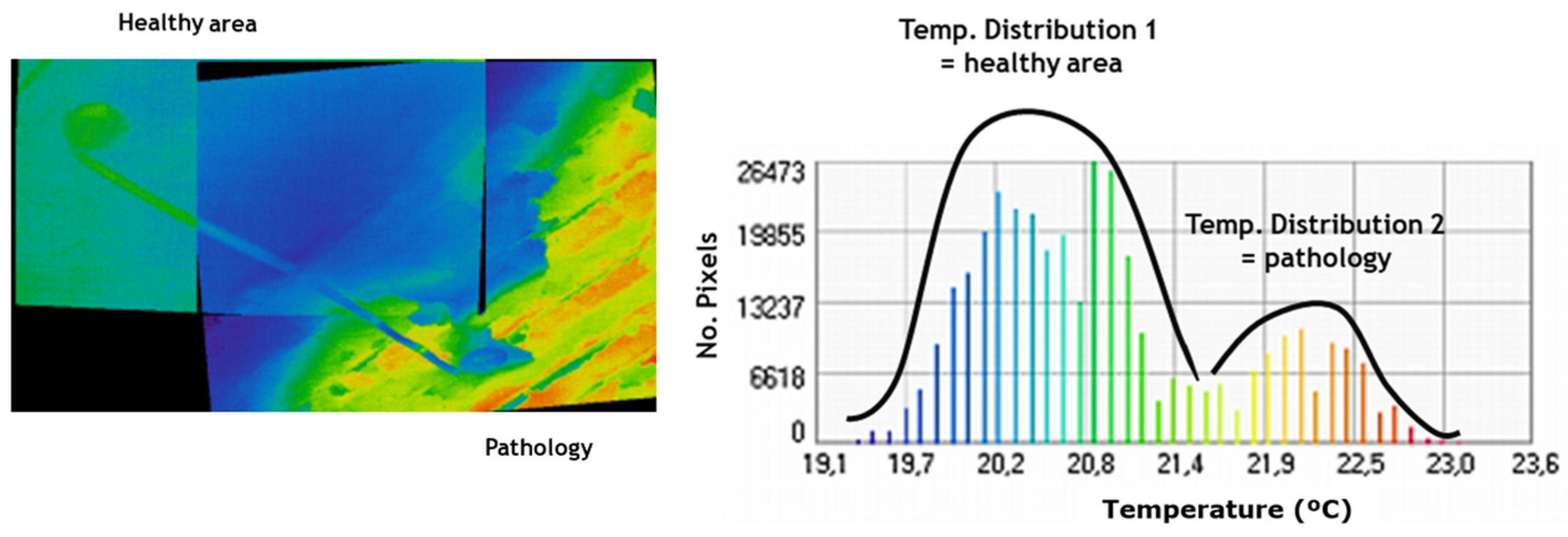
Figure 4.
(a) Trace plot where range 0–6 ns has been highlighted in red and peaks marked in green; (b) table showing the information (travel-time distance, sample number, sample value, amplitude) related to some of the peaks in the plot.
Figure 4.
(a) Trace plot where range 0–6 ns has been highlighted in red and peaks marked in green; (b) table showing the information (travel-time distance, sample number, sample value, amplitude) related to some of the peaks in the plot.
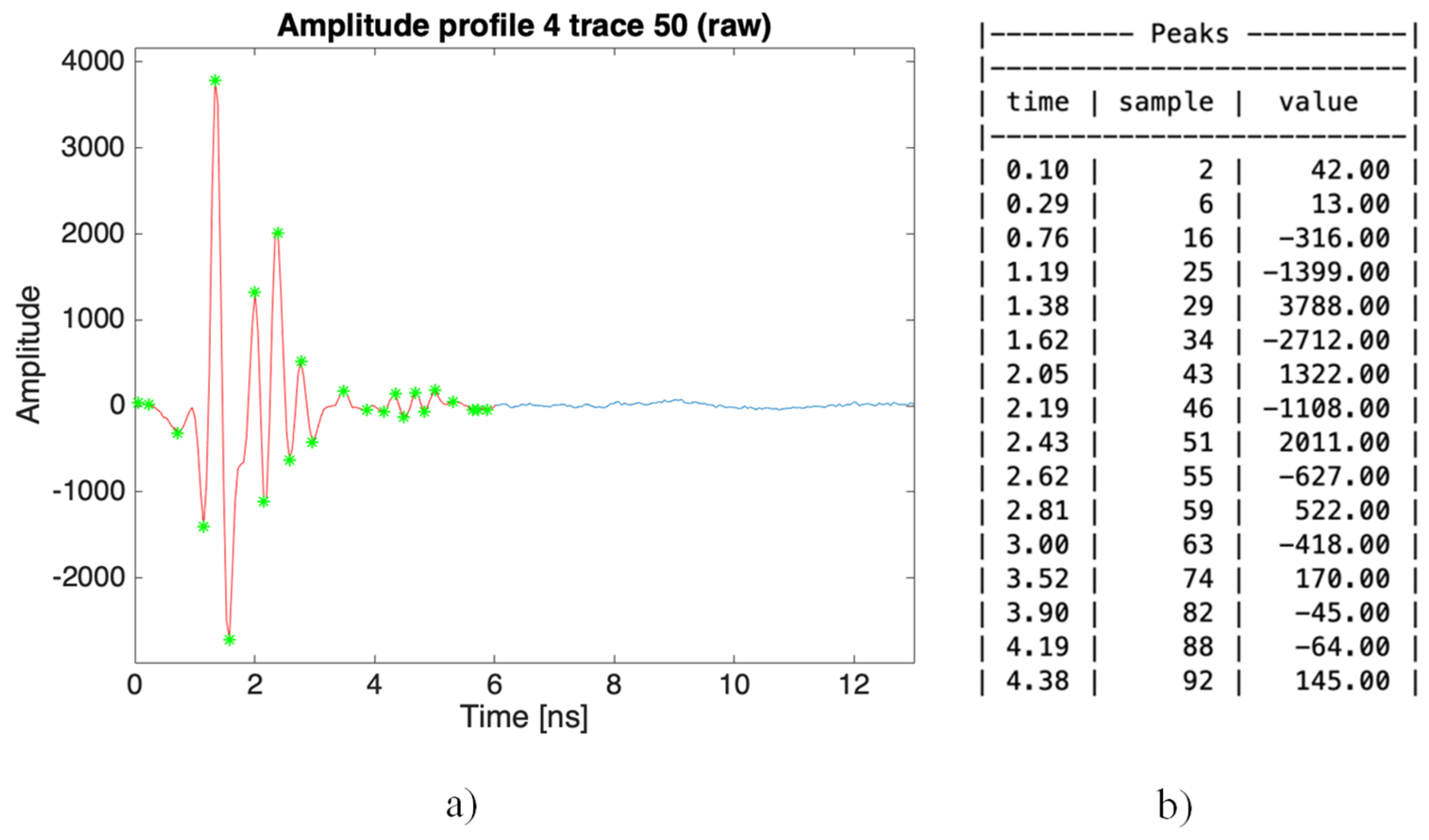
Figure 5.
Graphics obtained for GPR profile 1 and interpretation. The five hyperbolic reflections (rebars) produced in this profile line are indicated in graphs (a–c) as H1 to H5. The red circles in (d) represent a positive polarity of the reflections produced by the rebars.
Figure 5.
Graphics obtained for GPR profile 1 and interpretation. The five hyperbolic reflections (rebars) produced in this profile line are indicated in graphs (a–c) as H1 to H5. The red circles in (d) represent a positive polarity of the reflections produced by the rebars.
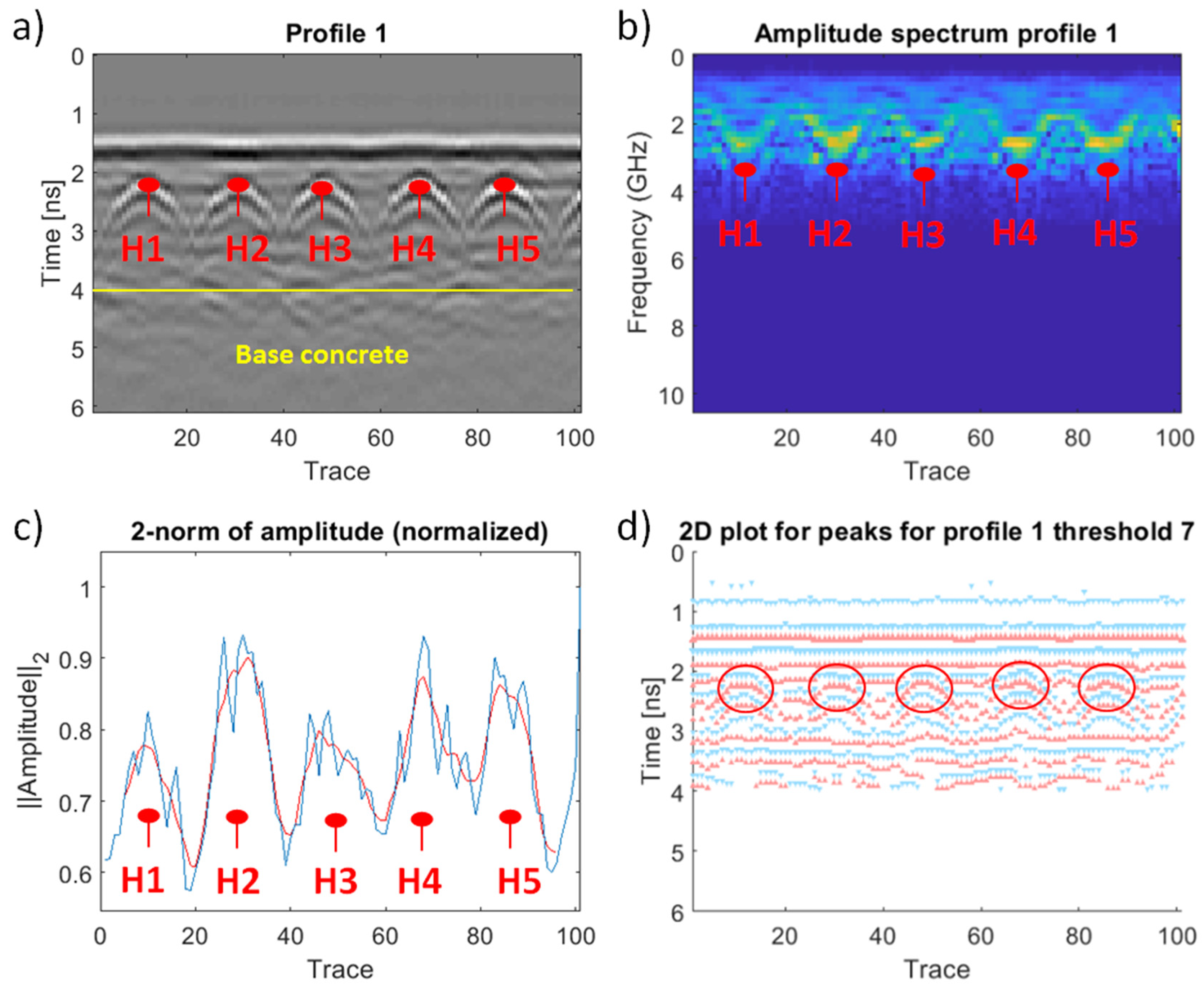
Figure 6.
Graphics obtained for GPR profile 2 and interpretation. The olive-green rectangles in (a–c) represent voids or delamination and orange rectangles indicate open-air rebars. The red circles in (d) represent a positive polarity of the reflections produced by the rebars, while the olive-green circles represent a negative signal polarity due to the presence of voids.

Figure 7.
Graphics obtained for GPR profile 3 and interpretation. The olive-green rectangles in (a–c) represent voids or delamination and orange rectangles indicate open-air rebars. The red circles in (d) represent a positive polarity of the reflections produced by the rebars, while the olive-green circles represent a negative signal polarity due to the presence of voids and lawn green rectangles correspond to moist areas.

Figure 8.
Graphics obtained for GPR profile 4 and interpretation. The orange rectangles in graphs (a–c) indicate open-air rebars, while the lawn green arrows in (a) correspond to moist areas and the olive-green arrows are associated to detachment. The red circles in (d) represent a positive polarity of the reflections produced by the rebars, while the lawn green rectangles represent a negative signal polarity associated to moist areas and the orange rectangles correspond to open-air rebars.
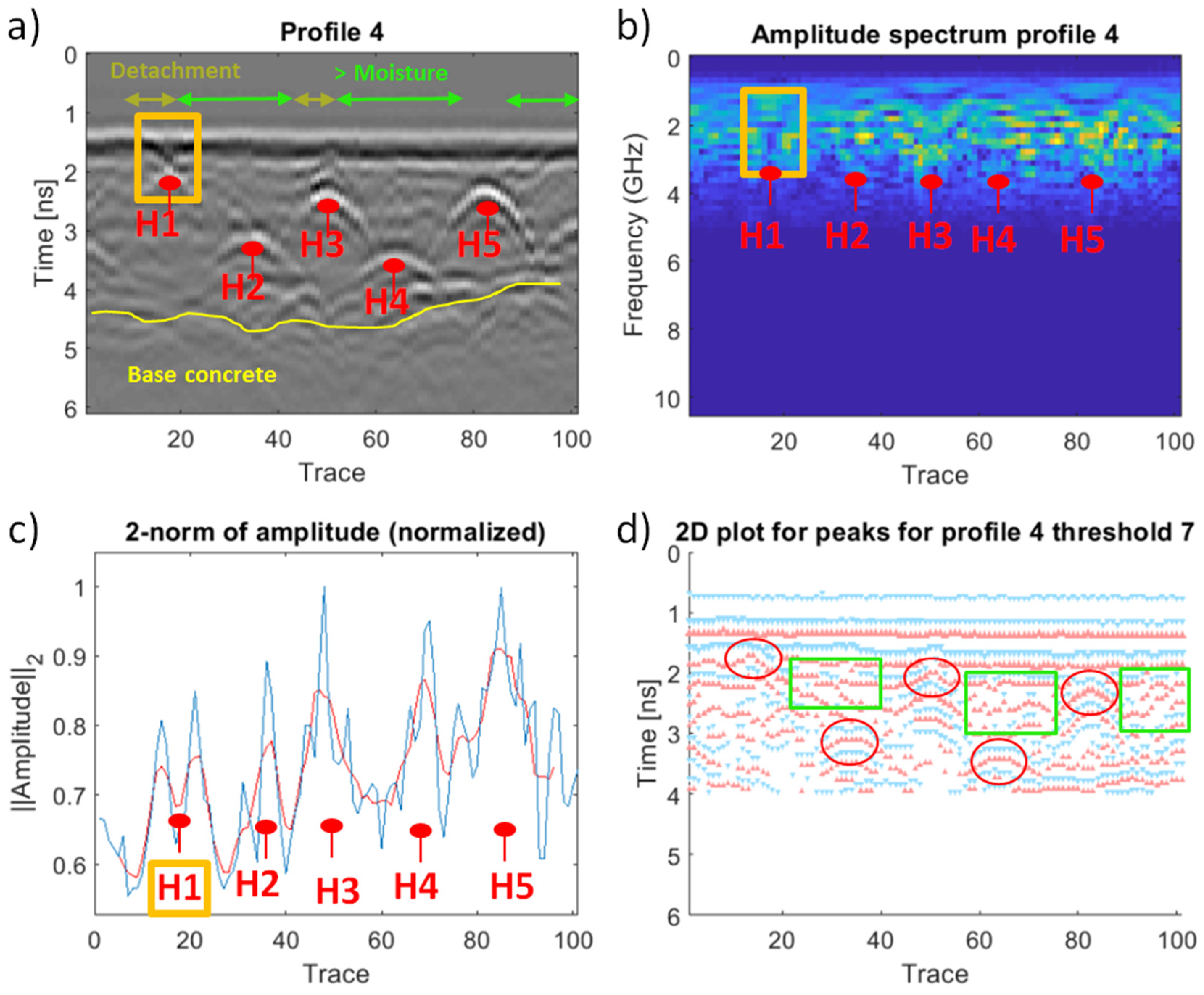
Figure 9.
Graphics obtained for GPR profile 5 and interpretation. The pink arrow in (a) represents a zone with high salt concentration, while the lawn green arrow indicates higher moisture. The orange rectangles in (a–c) indicate open-air rebars. The red circles in (d) represent a positive polarity of the reflections produced by the rebars, while the lawn green rectangle represents negative polarity due to moisture.

Figure 10.
Graphics obtained for GPR profile 6 and interpretation. The orange rectangles in (a–c) indicate open-air rebars while pink arrows are associated to zones with high salt concentration. The red circles in (d) represent a positive polarity of the reflections produced by the rebars.
Figure 10.
Graphics obtained for GPR profile 6 and interpretation. The orange rectangles in (a–c) indicate open-air rebars while pink arrows are associated to zones with high salt concentration. The red circles in (d) represent a positive polarity of the reflections produced by the rebars.

Figure 11.
Temperature evolution for each profile line with the corresponding visible and thermographic images for context information.
Figure 11.
Temperature evolution for each profile line with the corresponding visible and thermographic images for context information.

Table 1.
Description of the test site and GPR profile lines acquired.
| GPR Profile | Length | Description | Image |
|---|---|---|---|
| 1 | 1 m | Zone without pathologies used as a reference |  |
| 2 | 1 m | Zone with high presence of moisture, fissuration, delamination, and calcium carbonate salts |  |
| 3 | 1 m | Moisture, fissuration, delamination, rust, and calcium carbonate salts |  |
| 4 | 1 m | Fractures, cracks, concrete detachment, spalling, corroded steel rebars, and calcium carbonate salts |  |
| 5 | 1 m | Moisture, concrete detachment, spalling, corroded steel rebars, rust, and calcium carbonate salts |  |
| 6 | 0.8 m | Moisture, concrete detachment, spalling, corroded steel rebars, and calcium carbonate salts |  |
Table 2.
Filters used for GPR data processing.
| Filters | Parameters |
|---|---|
| Subtract-DC-Shift | Time window: 9–12 ns |
| Gain Function (Linear Exponential) | Linear: 1 & Exponential: 1 |
| Subtracting average | Traces: 250 |
| Bandpass (Butterworth) | Low cut: 500 MHz & High cut: 5000 MHz |
Table 3.
Amplitude (A) values and travel-time distances (twt) measured on the traces where the main focuses of the hyperbolas were registered. The numbering of the hyperbolic reflections (H) and the colors are in concordance with those in Figure 5, Figure 6, Figure 7, Figure 8, Figure 9 and Figure 10.
| H | 1 | 2 | 3 | 4 | 5 | 6 | 7 | 8 | ||
|---|---|---|---|---|---|---|---|---|---|---|
| Profile 1 | Trace | 11 | 30 | 48 | 68 | 86 | ||||
| A | Peak 1 | −1732 | −1603 | −1869 | −2329 | −2188 | ||||
| Peak 2 | 2883 | 3016 | 3153 | 3285 | 3198 | |||||
| Peak 3 | −1269 | −1216 | −1391 | −1512 | −1577 | |||||
| twt (ns) | Peak 1 | 2.09 | 2.09 | 2.09 | 2.05 | 2.09 | ||||
| Peak 2 | 2.28 | 2.28 | 2.24 | 2.24 | 2.24 | |||||
| Peak 3 | 2.43 | 2.48 | 2.43 | 2.43 | 2.43 | |||||
| Profile 2 | Trace | 6 | 28 | 38 | 46 | 60 | 72 | 81 | 99 | |
| A | Peak 1 | −3271 | −3801 | 1102 | −1107 | 1807 | 1001 | −7482 | −923 | |
| Peak 2 | 5743 | 5735 | −1008 | 2100 | −2201 | −2492 | 6480 | 2387 | ||
| Peak 3 | −2637 | −2924 | 667 | −836 | 1952 | 2559 | −3270 | −1239 | ||
| twt (ns) | Peak 1 | 1.81 | 1.76 | 1.81 | 2.05 | 1.81 | 1.76 | 1.66 | 2.43 | |
| Peak 2 | 2.00 | 1.95 | 1.95 | 2.33 | 1.95 | 1.90 | 1.86 | 2.57 | ||
| Peak 3 | 2.19 | 2.14 | 2.14 | 2.57 | 2.14 | 2.05 | 2.05 | 2.76 | ||
| Profile 3 | Trace | 3 | 17 | 30 | 47 | 67 | 77 | 85 | 98 | |
| A | Peak 1 | −690 | −1699 | −423 | −3748 | −741 | 1986 | −1892 | −788 | |
| Peak 2 | 1645 | 3491 | 1019 | 4155 | 1216 | −2722 | 3636 | 1055 | ||
| Peak 3 | −790 | −1567 | −400 | −1778 | −713 | 2749 | −1467 | −495 | ||
| twt (ns) | Peak 1 | 2.57 | 1.81 | 2.71 | 1.71 | 2.76 | 1.76 | 1.85 | 2.9 | |
| Peak 2 | 2.76 | 1.95 | 2.90 | 1.90 | 3.00 | 1.95 | 2.05 | 3.09 | ||
| Peak 3 | 2.95 | 2.14 | 3.14 | 2.09 | 3.19 | 2.09 | 2.24 | 3.33 | ||
| Profile 4 | Trace | 18 | 36 | 50 | 63 | 82 | ||||
| A | Peak 1 | −2401 | −734 | −1108 | −711 | −1412 | ||||
| Peak 2 | −2015 | 1175 | 2011 | 745 | 2610 | |||||
| Peak 3 | 2110 | −845 | −627 | −284 | −928 | |||||
| twt (ns) | Peak 1 | 1.62 | 2.95 | 2.19 | 3.28 | 2.14 | ||||
| Peak 2 | 1.81 | 3.14 | 2.43 | 3.48 | 2.33 | |||||
| Peak 3 | 2.00 | 3.33 | 2.62 | 3.62 | 2.52 | |||||
| Profile 5 | Trace | 12 | 28 | 52 | 67 | 83 | ||||
| A | Peak 1 | −6486 | −5411 | −6126 | −5534 | −6145 | ||||
| Peak 2 | 5830 | 5037 | 3038 | 3706 | 3759 | |||||
| Peak 3 | −2982 | −2687 | −1079 | −1982 | −2234 | |||||
| twt (ns) | Peak 1 | 1.62 | 1.62 | 1.52 | 1.52 | 1.52 | ||||
| Peak 2 | 1.81 | 1.86 | 1.71 | 1.67 | 7.71 | |||||
| Peak 3 | 2.00 | 2.00 | 1.86 | 1.86 | 1.86 | |||||
| Profile 6 | Trace | 18 | 30 | 53 | 67 | |||||
| A | Peak 1 | −5827 | −8614 | −3748 | −8369 | |||||
| Peak 2 | 3674 | 8389 | 2778 | 7431 | ||||||
| Peak 3 | −1403 | −4962 | −588 | −3937 | ||||||
| twt (ns) | Peak 1 | 1.57 | 1.62 | 1.57 | 1.57 | |||||
| Peak 2 | 1.81 | 1.76 | 1.90 | 1.76 | ||||||
| Peak 3 | 2.05 | 1.95 | 2.09 | 1.90 | ||||||
Table 4.
Delimitation of pathologies and interpretation. Humidity is detected by its lower temperature regarding the environment, due to its higher thermal inertia. The delimitation is shown with a white line, placed on the original thermal image.
Table 4.
Delimitation of pathologies and interpretation. Humidity is detected by its lower temperature regarding the environment, due to its higher thermal inertia. The delimitation is shown with a white line, placed on the original thermal image.
| PROFILE | IMAGE 1 | IMAGE 2 | INTERPRETATION |
|---|---|---|---|
| Profile 1 |  |  | No pathologies are detected nor delimited |
| Profile 2 |  |  | Delimitation of detachment and moisture. The pathologies are considered as one, no differentiation is possible between them |
| Profile 3 |  |  | Constant moisture |
| Profile 4 |  |  | Moisture + detached areas in the surroundings of the profile |
| Profile 5 |  |  | Image 1—moisture Image 2—border of the concrete detachment, caused by the moisture detected. The contour of the mineral salts cannot be detected with the methodology, due to their low importance regarding the number of pixels in comparison with the moisture |
| Profile 6 |  |  | Image 1, 2—borders of concrete detachment, caused by moisture. Again, the contour of the mineral salts cannot be detected with the methodology due to their low importance regarding the number of pixels in comparison with the detachment |
Table 5.
Behavior of the GPR signal and the apparent temperature for each pathology.
| Anomalies | GPR | IRT |
|---|---|---|
| Visible rebars (corroded material) |
|
|
| Moisture |
|
|
| Mineral salts |
|
|
| Detachments |
|
|
| Voids |
|
|
© 2019 by the authors. Licensee MDPI, Basel, Switzerland. This article is an open access article distributed under the terms and conditions of the Creative Commons Attribution (CC BY) license (http://creativecommons.org/licenses/by/4.0/).
Share and Cite
MDPI and ACS Style
Solla, M.; Lagüela, S.; Fernández, N.; Garrido, I. Assessing Rebar Corrosion through the Combination of Nondestructive GPR and IRT Methodologies. Remote Sens. 2019, 11, 1705. https://0-doi-org.brum.beds.ac.uk/10.3390/rs11141705
AMA Style
Solla M, Lagüela S, Fernández N, Garrido I. Assessing Rebar Corrosion through the Combination of Nondestructive GPR and IRT Methodologies. Remote Sensing. 2019; 11(14):1705. https://0-doi-org.brum.beds.ac.uk/10.3390/rs11141705
Chicago/Turabian StyleSolla, Mercedes, Susana Lagüela, Norberto Fernández, and Iván Garrido. 2019. "Assessing Rebar Corrosion through the Combination of Nondestructive GPR and IRT Methodologies" Remote Sensing 11, no. 14: 1705. https://0-doi-org.brum.beds.ac.uk/10.3390/rs11141705
Note that from the first issue of 2016, this journal uses article numbers instead of page numbers. See further details here.