Long Integral Time Continuous Panorama Scanning Imaging Based on Bilateral Control with Image Motion Compensation


Abstract
:1. Introduction
2. Problem Formulation
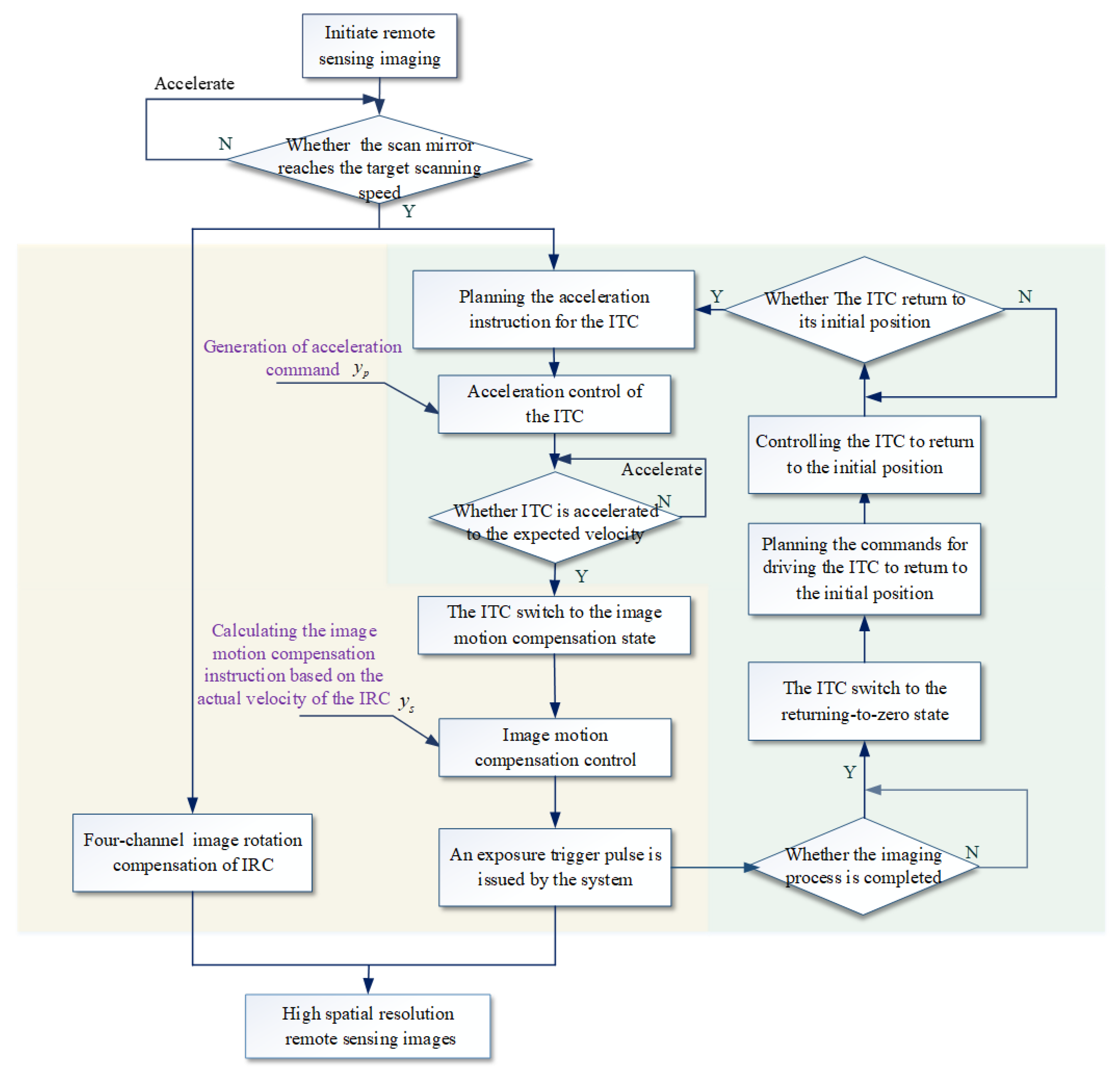
3. Control Strategy of Image Motion
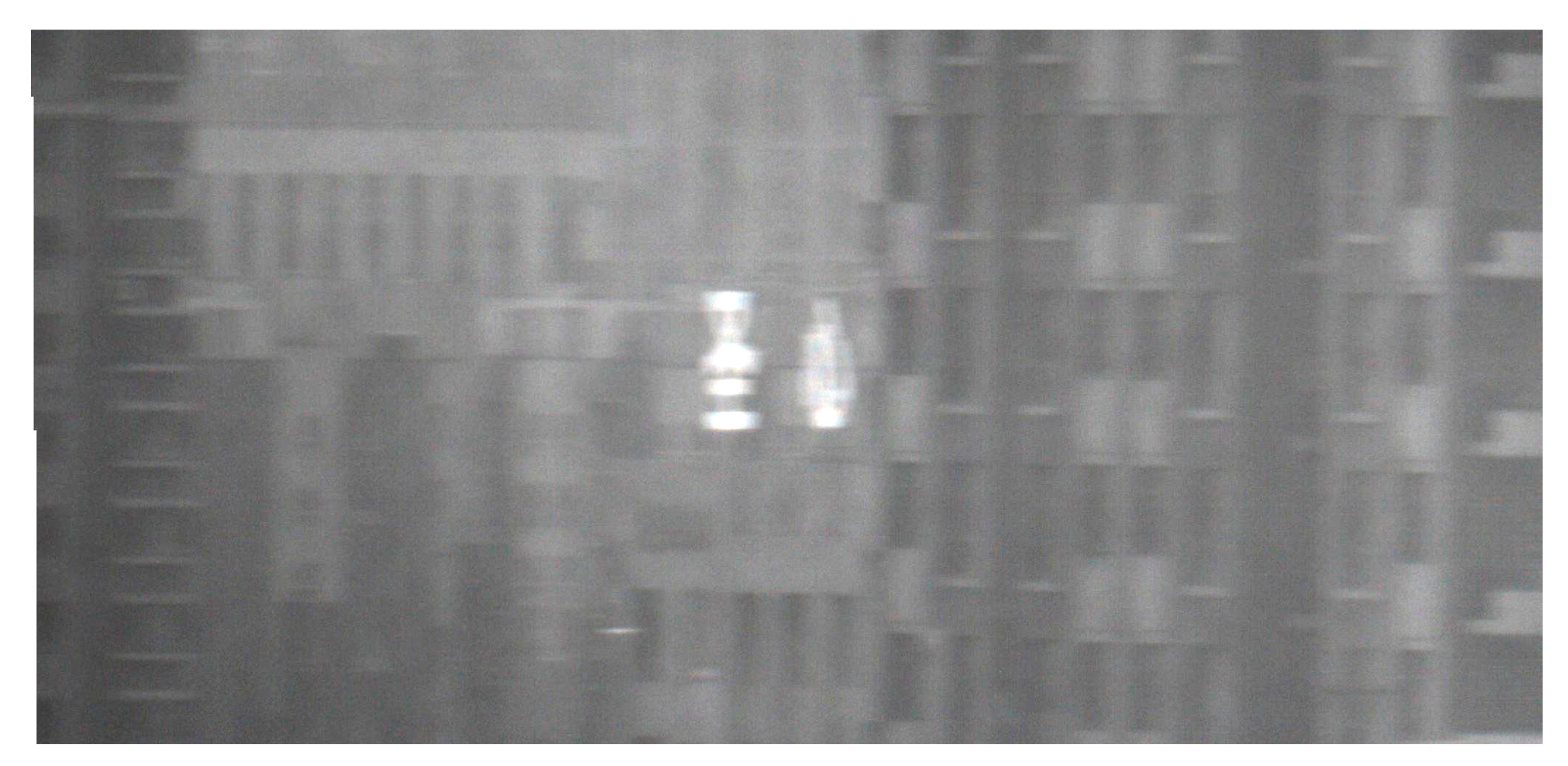
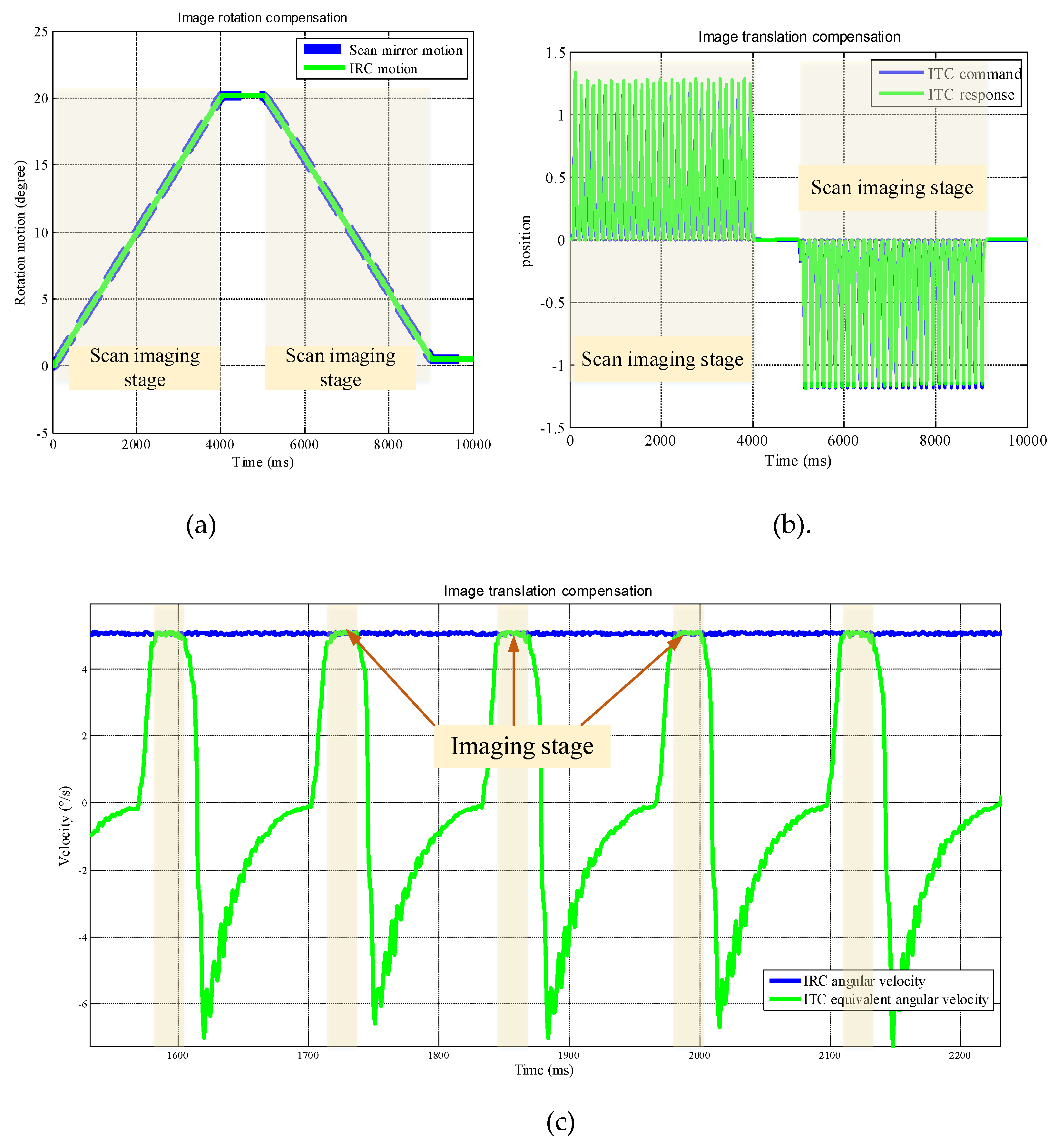
4. Experimental Results
5. Discussion
6. Conclusions
Author Contributions
Funding
Conflicts of Interest
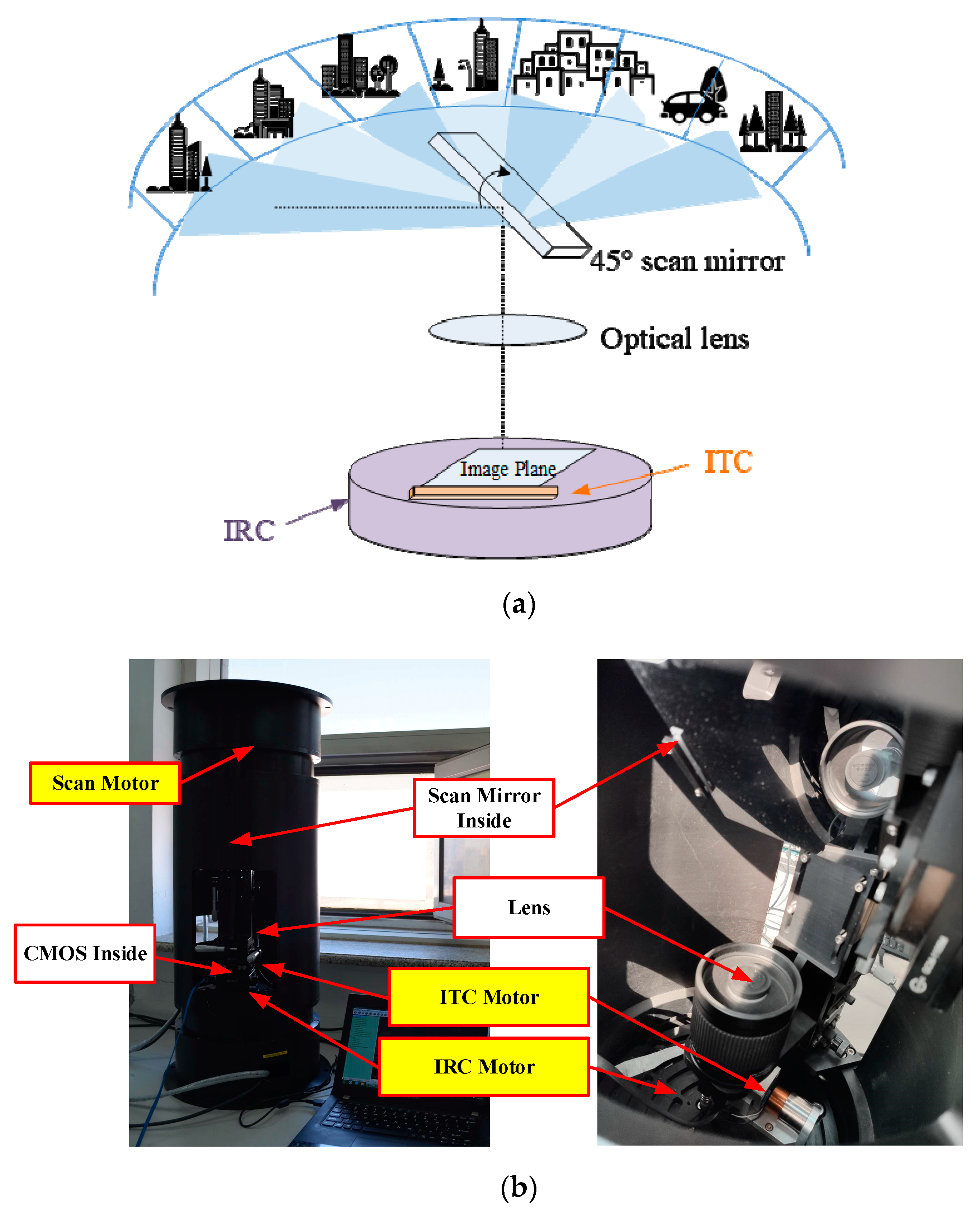
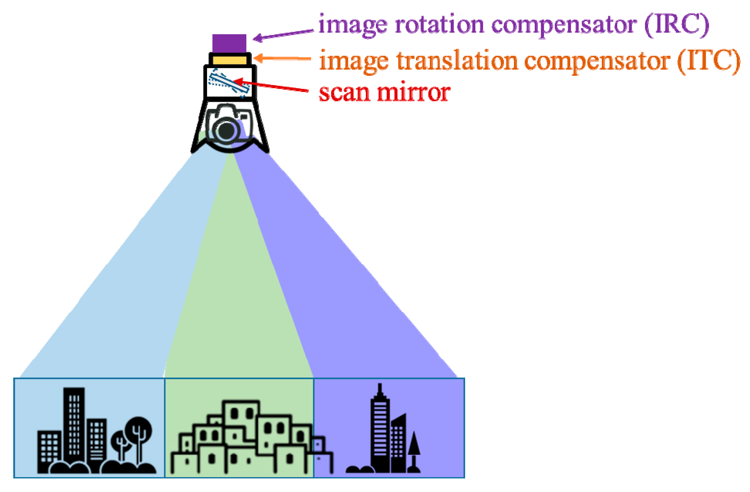
Appendix A. Working Principle of the System
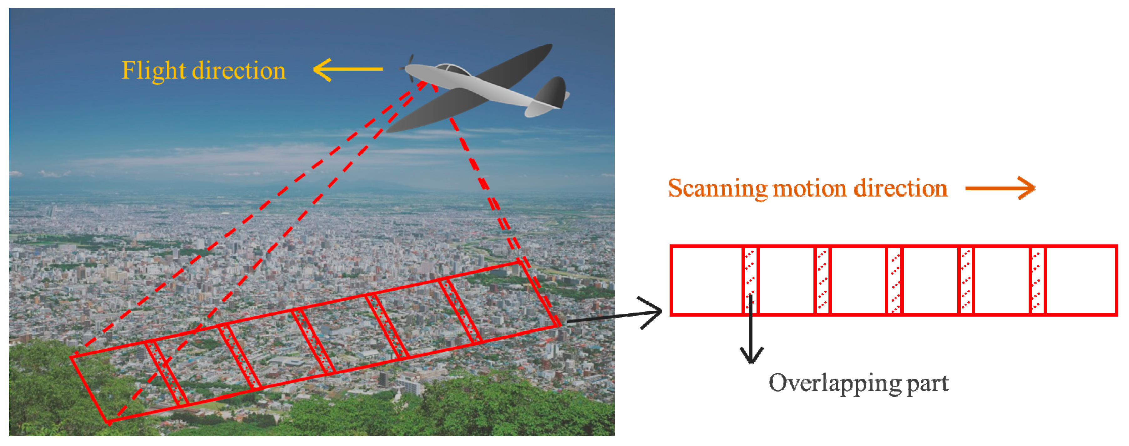
Appendix A.1. Working Principle of the System


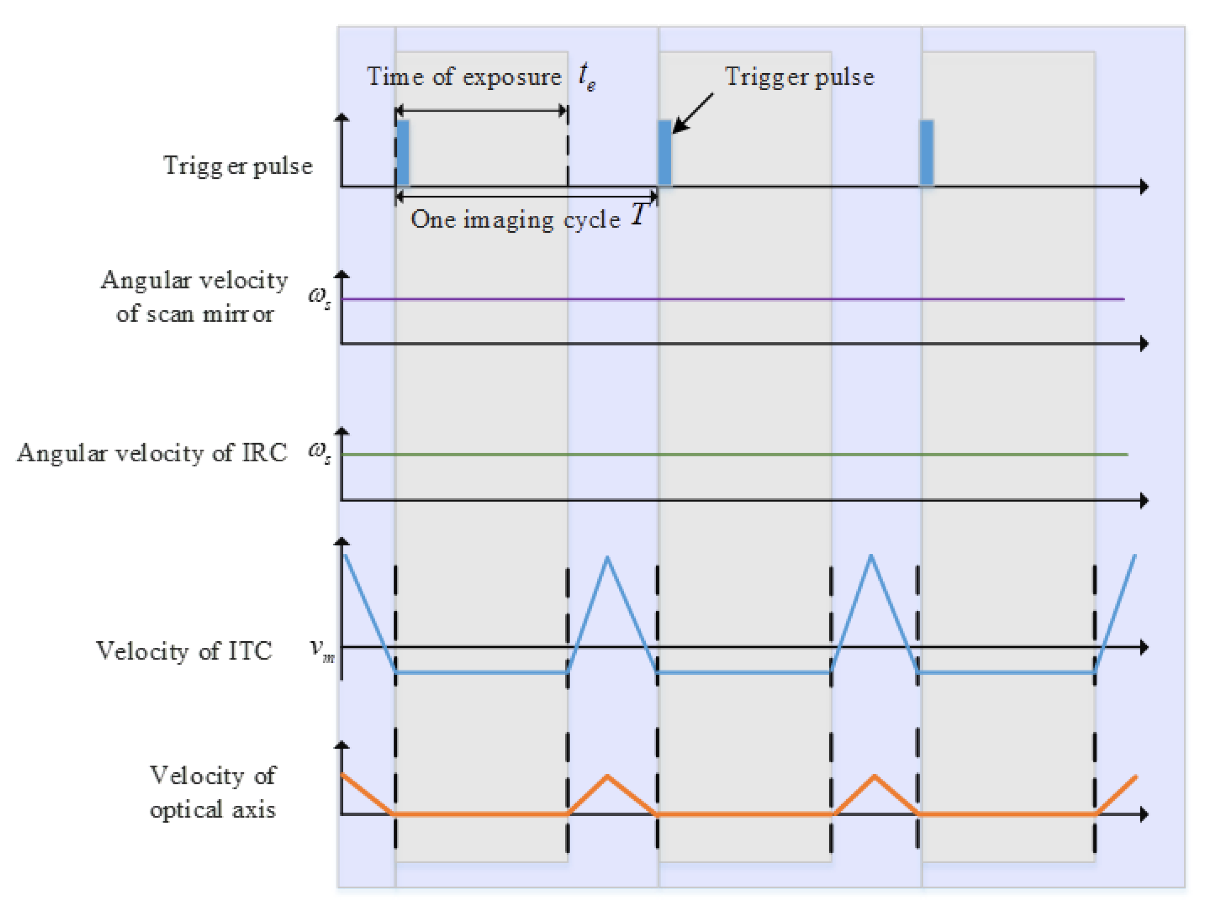
Appendix A.2. Formation Principle of Imaging Motion
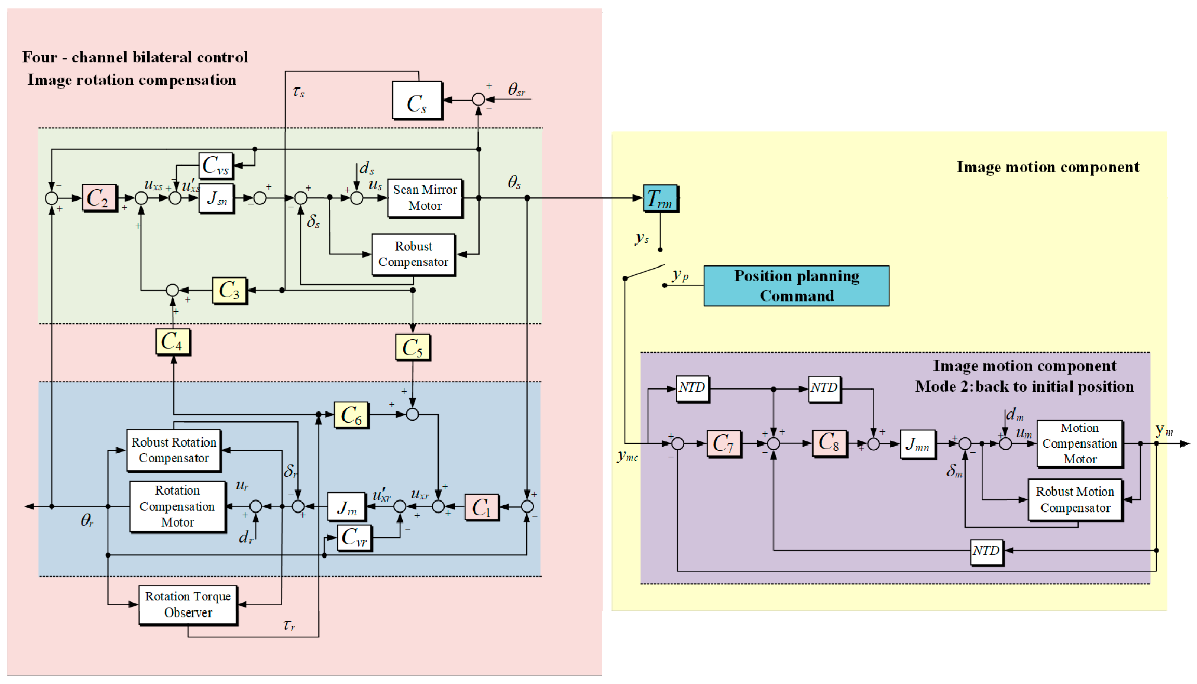
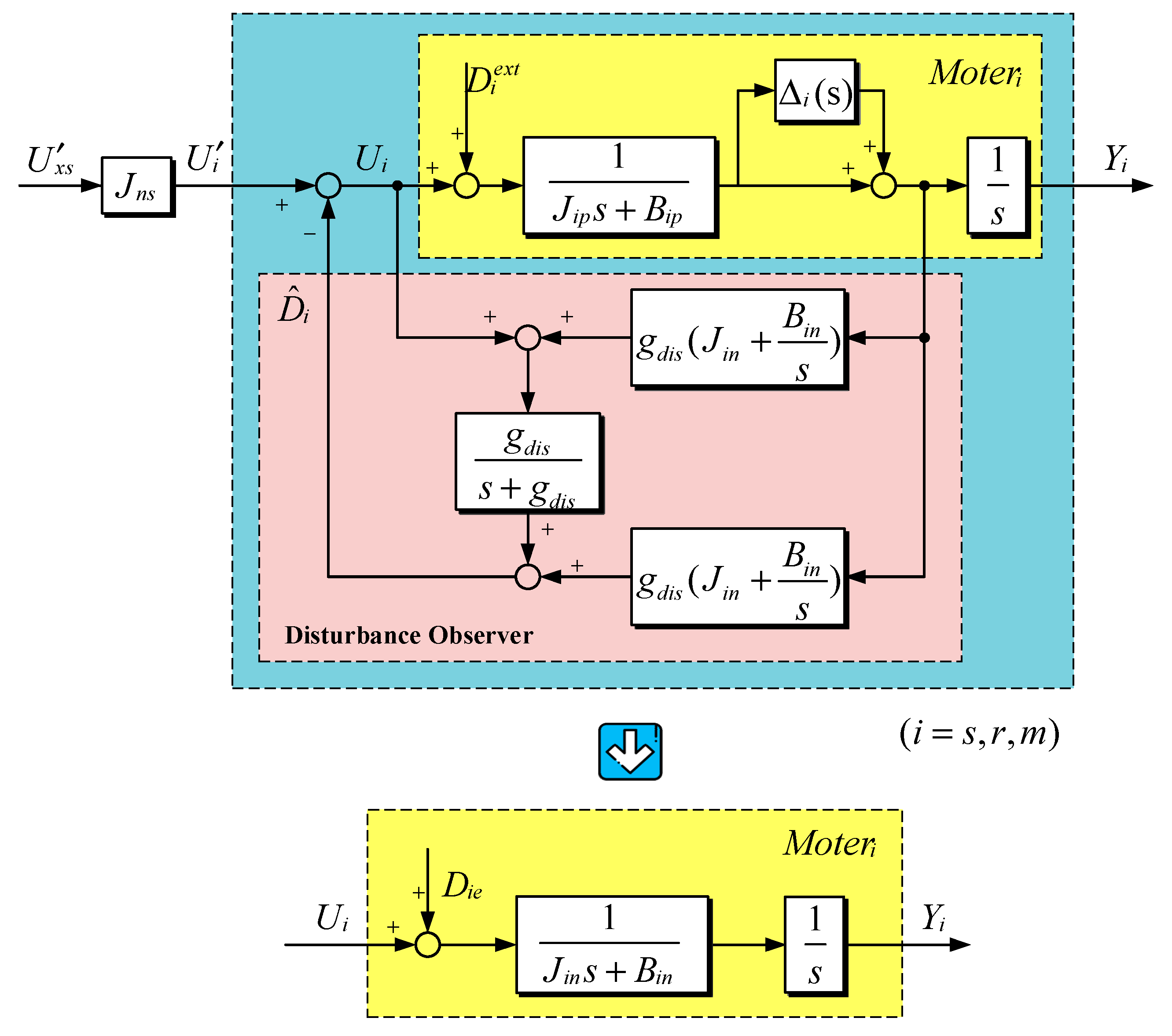
Appendix B. Controller Design

References
- Koc, C.B.; Osmond, P.; Peters, A.; Irger, M. Mapping Local Climate Zones for urban morphology classification based on airborne remote sensing data. In Proceedings of the 2017 Joint Urban Remote Sensing Event (JURSE), Dubai, UAE, 6–8 March 2017. [Google Scholar]
- See, L.; Perger, C.; Duerauer, M.; Fritz, S.; Bechtel, B.; Ching, J.; Alexander, P.; Mills, G.; Foley, M.; Connor, M.; et al. Developing a community-based worldwide urban morphology and materials database (WUDAPT) using remote sensing and crowdsourcing for improved urban climate modelling. In Proceedings of the 2015 Joint Urban Remote Sensing Event (JURSE), Lausanne, Switzerland, 30 March–1 April 2015. [Google Scholar]
- Wang, J.; Zhan, Q.M.; Guo, H.G. The Morphology, Dynamics and Potential Hotspots of Land Surface Temperature at a Local Scale in Urban Areas. Remote. Sens. 2016, 8, 18. [Google Scholar] [CrossRef]
- Shi, L.; Liu, F.; Zhang, Z.; Zhao, X. Monitoring Urban Expansion and Morphology Changes of Tangshan by Using Remote Sensing. In Communications in Computer and Information Science; Springer: Berlin/Heidelberg, Germany, 2015; Volume 482, pp. 625–634. [Google Scholar]
- Taubenböck, H.; Standfuß, I.; Wurm, M.; Krehl, A.; Siedentop, S. Measuring morphological polycentricity-A comparative analysis of urban mass concentrations using remote sensing data. Comput. Environ. Urban. Syst. 2017, 64, 42–56. [Google Scholar] [CrossRef]
- Xie, J.; Chen, H.; Tan, Z.; Hou, D.; Wang, X. Real-time adjustment of optical transmitter by laser beam parameter measurement based on two linear array CCD scanning imaging. Optik 2014, 125, 3991–3995. [Google Scholar] [CrossRef]
- Yoon, Y.; Yu, G.; Noh, C.; Song, D. Robust scanning scheme over large area for airborne EO/IR camera. Electro-Opt. Infrared Syst. Technol. Appl. VIII 2011, 8185, 81850X. [Google Scholar]
- Yu, C.; Ding, Y.; Hui, S.; Zhang, J.; Leng, X. Analysis of image rotation for aerial remote sensor with off-axis three-reflective optical system. Phys. Procedia 2012, 24, 225–232. [Google Scholar]
- Zheng, T.; Cao, L.; He, Q.; Jin, G. Image rotation measurement in scene matching based on holographic optical correlator. Appl. Opt. 2013, 52, 2841–2848. [Google Scholar] [CrossRef] [PubMed]
- Yu, J.; Craver, S. A fast automatic camera image stabilization benchmarking scheme. Int. Soc. Opt. Photonics 2012, 8293, 7. [Google Scholar]
- Sun, H.; Zhang, S.M. Computation model and error budget for image motion of aerial imaging system. Opt. Precis. Eng. 2012, 20, 2492–2499. (In Chinese) [Google Scholar] [CrossRef]
- Chen, Q. Analysis and correction of the image aberration of 45° directional mirror. Infrared Laser Eng. 2010, 39, 301–305. [Google Scholar]
- Ren, H.; Hu, T.T.; Song, Y.L.; Sun, H.; Liu, B.C.; Gao, M.H. An Improved Electronic Image Motion Compensation (IMC) Method of Aerial Full-Frame-Type Area Array CCD Camera Based on the CCD Multiphase Structure and Hardware Implementation. Sensors 2018, 18, 2632. [Google Scholar] [CrossRef] [PubMed]
- Zheng, T.; Cao, L.; He, Q.; Jin, G. Full-range in-plane rotation measurement for image recognition with hybrid digital-optical correlator. Opt. Eng. 2013, 53, 011003. [Google Scholar] [CrossRef]
- Hu, Q.L. Optical and Mechanical Structure Design and Research on Image Motion Compensation Technology of Whisking Broom Space-based Infrared Imaging System. Ph.D. Dissertation, University of Chinese Academy of Sciences, Changchun, China, 2018. (In Chinese). [Google Scholar]
- Zhang, J.C.; Zhou, J.F.; Zhang, L. Image spin compensation on scanning frame remote sensor. Infrared Laser Eng. 2012, 41, 2396–2400. [Google Scholar]
- Sando, Y.; Barada, D.; Yatagai, T. Optical rotation compensation for a holographic 3D display with a 360 degree horizontal viewing zone. Appl. Opt. 2016, 55, 8589–8595. [Google Scholar] [CrossRef] [PubMed]
- Li, X.Y.; Zhang, T.; Liu, Z.M.; Li, W.M. High accuracy compensation for image surface rotation of panoramic TDICCD scanning aerial camera. Acta Opt. Sin. 2014, 34, 0611001. [Google Scholar]
- Li, Z.J.; Chen, X.L. Study of image motion compensation in spectral imaging system. In Proceedings of the 8th International Symposium on Advanced Optical Manufacturing and Testing Technologies: Large Mirrors and Telescopes, Suzhou, China, 24 October 2016. [Google Scholar]
- Tian, D.P.; Wang, Y.T.; Wang, F.C.; Zhang, Y.P. Bilateral control-based compensation for rotation in imaging in scan imaging systems. Opt. Eng. 2015, 54, 124104. [Google Scholar] [CrossRef]
- Tian, D.P. Advanced Motion Control for Real-World Haptic Communication; Jilin People’s Publishing House: Chagnchun, China, 2015; pp. 82–95. [Google Scholar]
- Tian, D.P.; Shen, H.H.; Dai, M. Improving the rapidity of nonlinear tracking differentiator via feedforward. IEEE Trans. Ind. Electron. 2014, 61, 3736–3743. [Google Scholar] [CrossRef]


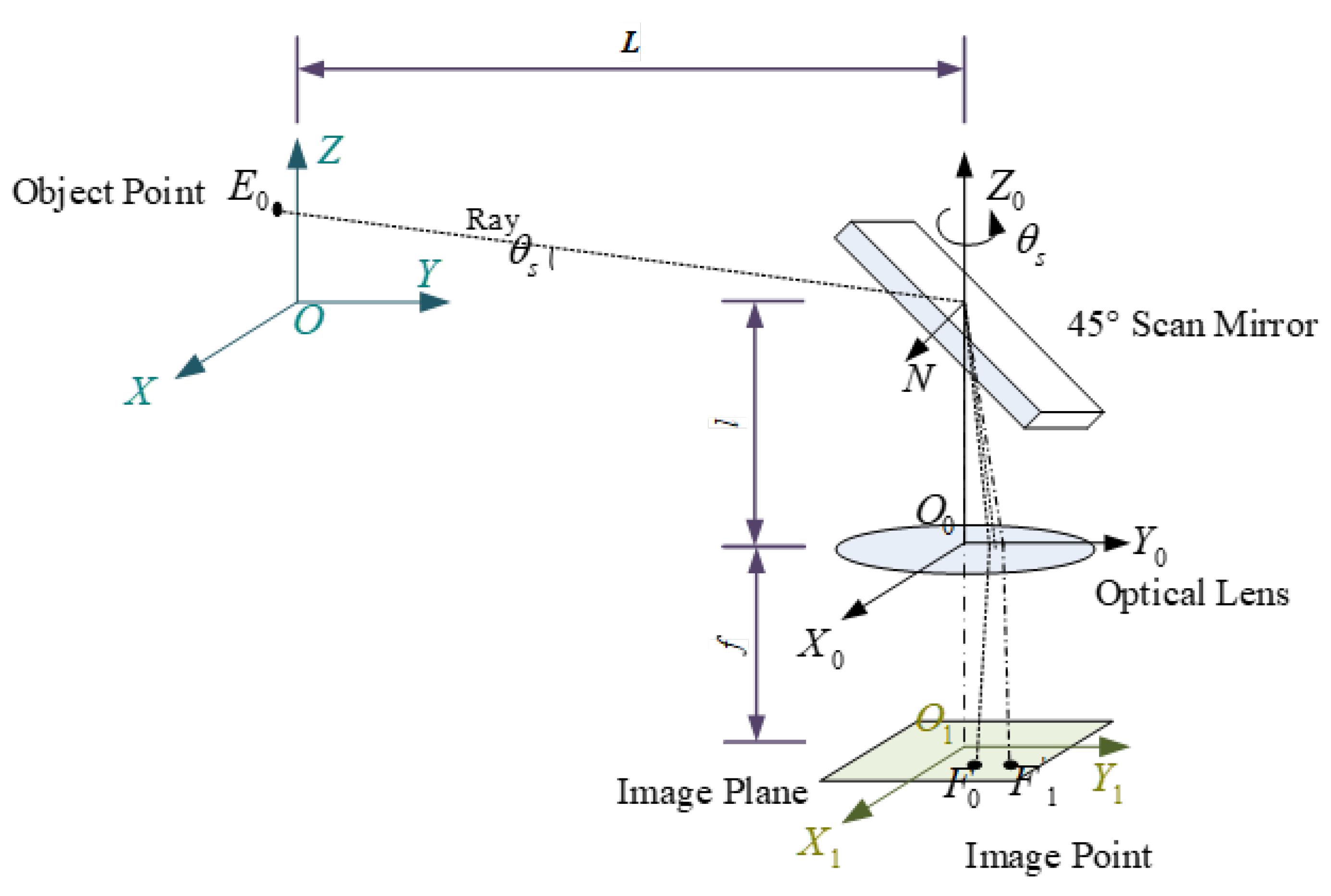
| Parameter | Simulation Value | Unit |
|---|---|---|
| distance between the object and the scan mirror | 2000 | m |
| distance between the scan mirror and the lens | 0.4 | m |
| focal distance of the lens | 0.3 | m |
| number of pixels in the image plane | 2048 × 2048 | / |
| physical size of a pixel | 5.3 | μm |
| the scanning velocity of the scan mirror | 8 | °/s |
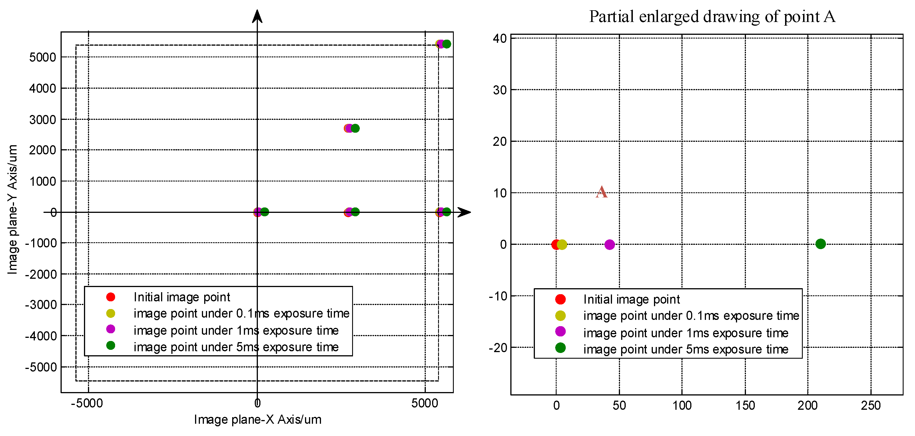
| Image Points | |
|---|---|
| Point A | (0,0) |
| Point B | (512,0) |
| Point C | (1024,0) |
| Point D | (512,−512) |
| Point E | (1024,−1024) |
| Image Point | Exposure Time 0.1 ms | Exposure Time 1 ms | Exposure Time 5 ms | |||
|---|---|---|---|---|---|---|
| x-axis | y-axis | x-axis | y-axis | x-axis | y-axis | |
| Point A | 7.9 × 10⁻¹ | 1.1 × 10⁻⁵ | 7.903 | 1.1 × 10⁻³ | 39.52 | 2.8 × 10⁻² |
| Point B | 7.9 × 10⁻¹ | 7.2 × 10⁻³ | 7.904 | 7.3 × 10⁻² | 39.53 | 3.9 × 10⁻¹ |
| Point C | 7.9 × 10⁻¹ | 1.4 × 10⁻² | 7.906 | 1.4 × 10⁻¹ | 39.53 | 7.4 × 10⁻¹ |
| Point D | 7.8 × 10⁻¹ | 7.2 × 10⁻³ | 7.83 | 7.3 × 10⁻² | 39.2 | 3.9 × 10⁻¹ |
| Point E | 7.8 × 10⁻¹ | 1.4 × 10⁻² | 7.76 | 1.5 × 10⁻¹ | 38.8 | 7.6 × 10⁻¹ |
| Parameters and Marks | Value | Unit |
|---|---|---|
| Scan motor's nominal inertia | 0.004347826 | kgm2 |
| Scan motor's nominal viscous | 0.04347826 | s−1 |
| IRC motor's nominal inertia | 0.003125 | kgm2 |
| IRC motor's nominal viscous | 0.03125 | s−1 |
| ITC motor's nominal inertia | 0.0000714 | kgm2 |
| ITC motor's nominal viscous | 0.0007 | s−1 |
| IRC position control gain for torque controller | 200 | s−2 |
| IRC velocity control gain for torque controller | 20 | s−1 |
| ITC position control gain for torque controller | 200 | s−2 |
| ITC velocity control gain for torque controller | 20 | s−1 |
| sliding mode control parameter 1 | 1 | b1 |
| sliding mode control parameter 2 | 10 | b2 |
| torque control gain | 1.0 | Kt |
| DOB cutoff frequency | 300 | gdis |
| viscous compensation | 10 | ν |
| the scanning velocity of the scan mirror | 8 | °/s |
© 2019 by the authors. Licensee MDPI, Basel, Switzerland. This article is an open access article distributed under the terms and conditions of the Creative Commons Attribution (CC BY) license (http://creativecommons.org/licenses/by/4.0/).
Share and Cite
Tian, D.; Wang, Y.; Wang, Z.; Wang, F.; Gao, H. Long Integral Time Continuous Panorama Scanning Imaging Based on Bilateral Control with Image Motion Compensation. Remote Sens. 2019, 11, 1924. https://0-doi-org.brum.beds.ac.uk/10.3390/rs11161924
Tian D, Wang Y, Wang Z, Wang F, Gao H. Long Integral Time Continuous Panorama Scanning Imaging Based on Bilateral Control with Image Motion Compensation. Remote Sensing. 2019; 11(16):1924. https://0-doi-org.brum.beds.ac.uk/10.3390/rs11161924
Chicago/Turabian StyleTian, Dapeng, Yutang Wang, Zhongshi Wang, Fuchao Wang, and Huijun Gao. 2019. "Long Integral Time Continuous Panorama Scanning Imaging Based on Bilateral Control with Image Motion Compensation" Remote Sensing 11, no. 16: 1924. https://0-doi-org.brum.beds.ac.uk/10.3390/rs11161924