Mitigation of Radio Frequency Interference in Synthetic Aperture Radar Data: Current Status and Future Trends


1
Research & Development Institute of Northwestern Polytechnical University in Shenzhen, Shenzhen 518057, China
2
School of Electronics and Information, Northwestern Polytechnical University, Xi’an 710072, China
3
State Key Lab of Millimeter Waves, Southeast University, Nanjing 211100, China
*
Author to whom correspondence should be addressed.
Remote Sens. 2019, 11(20), 2438; https://0-doi-org.brum.beds.ac.uk/10.3390/rs11202438
Submission received: 29 September 2019
/
Revised: 13 October 2019
/
Accepted: 16 October 2019
/
Published: 21 October 2019
(This article belongs to the Special Issue Radio Frequency Interference (RFI) in Microwave Remote Sensing)
Abstract
:Radio frequency interference (RFI) is a major issue in accurate remote sensing by a synthetic aperture radar (SAR) system, which poses a great hindrance to raw data collection, image formation, and subsequent interpretation process. This paper provides a comprehensive study of the RFI mitigation techniques applicable for an SAR system. From the view of spectrum allocation, possible terrestrial and spaceborne RFI sources to SAR system and their geometry are analyzed. Typical signal models for various RFI types are provided, together with many illustrative examples from real measured data. Then, advanced signal processing techniques for removing RFI are reviewed. Advantages and drawbacks of each approach are discussed in terms of their applicability. Discussion on the future trends are provided from the perspective of cognitive, integrated, and adaptive. This review serves as a reference for future work on the implementation of the most suitable RFI mitigation scheme for an air-borne or space-borne SAR system.
1. Introduction
1.1. Congested Electromagnetic Environment
With the advancement of affordable electronics and mobile wireless technology, many more commercial and industry radio services emerged. Radio devices have an increasing demand for greater bandwidth, for example, the next generation communication networks need up to 1GHz bandwidth of additional spectrum to transmit ultra-high definition visual communications and immersive multimedia interactions. The radar system also requires larger bandwidth to obtain finer range resolution. Moreover, the growing reliance on unmanned platforms ranging from underwater sensors to satellites also acting as a push for contested access, which make the electromagnetic environment getting more congested and complex [1].
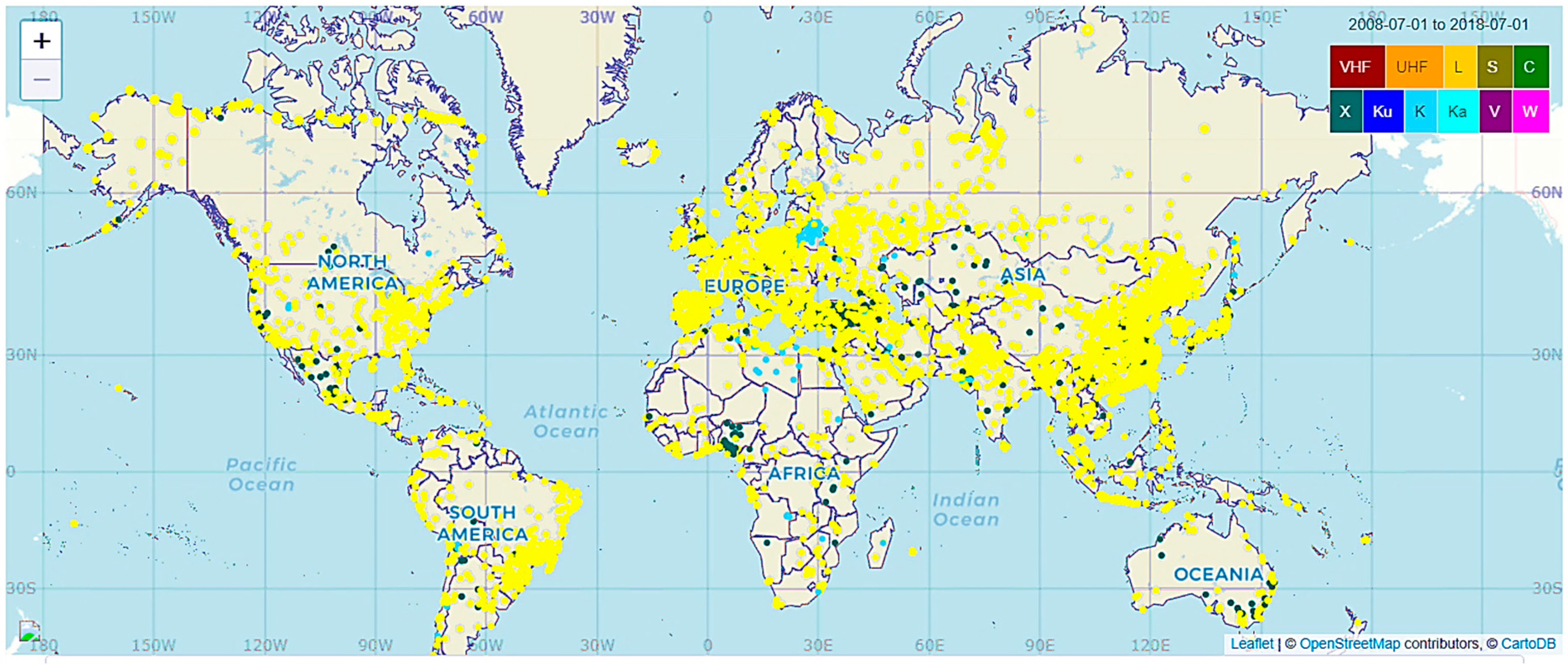
Synthetic aperture radar (SAR) is an active microwave remote sensing instrument that can provide essential data critical to understanding of global environmental change, which are important for a wide range of scientific, commercial, and defense applications. The proliferation of radio technology increases the likelihood of co-channel interference to active remote sensing systems, especially for those high-resolution SAR systems with large bandwidth like several hundred megahertz [2]. The interfering signal emitting from other radiation sources within the same frequency band are referred as radio frequency interference (RFI). It is common to find that SAR systems are susceptible to the RFI, especially in low-frequency bands like P and L band [3]. Figure 1 illustrates observed RFI cases from different frequency bands spreading over the global area [4]. The circles with different colors corresponding to the location of RFI sources observed in various frequency bands. It is shown that RFI at low band like L-band is abundant and spread worldwide. The RFI situation differs in geographical areas, in which the well-developed area with dense population is much more severe. For example, the situations in East Asia and Europe are much worse than regions like Canada and Australia. It is worth noting that this map does not report all occurrences of existing interference due to the limited number of monitoring sensors. In addition, RFI may still be present in other bands, even if it is not reported here.
1.2. Advese Impacts of RFI to SAR System
The presence of RFI is detrimental to global and regional scientific research activity of SAR. Depending on the application, SAR extracts information based on the characteristics of the echo including amplitude, frequency, time delay, polarization, Doppler shift, and phase [5]. RFI can corrupt the desired radar measurements in a number of ways, ranging from raw data collection, image formation, and the subsequent interpretation process.
1.2.1. Data Collection Process
In SAR raw echoes, the presence of RFI will reduce the signal to interference noise ratio (SINR), bury the scattering response of weak target, and distort the dynamic range of the raw echoes. Besides, the receiver is sensitive to saturation by high-power in-band emissions, especially when aimed towards the interfering sources in the main-lobe [6]. Figure 2 compares particular range spectrums of the real measured SAR echoes with and without RFI. The data is recorded by a Chinese L-band airborne SAR system with the bandwidth of 300 MHz. The echoes are linear frequency modulated, as shown in Figure 2a. Compared with Figure 2b, many RFI spikes existed and the power is dynamically varied, which significantly reduce the SINR and altering the spectrum shape.
1.2.2. Image Formation Process
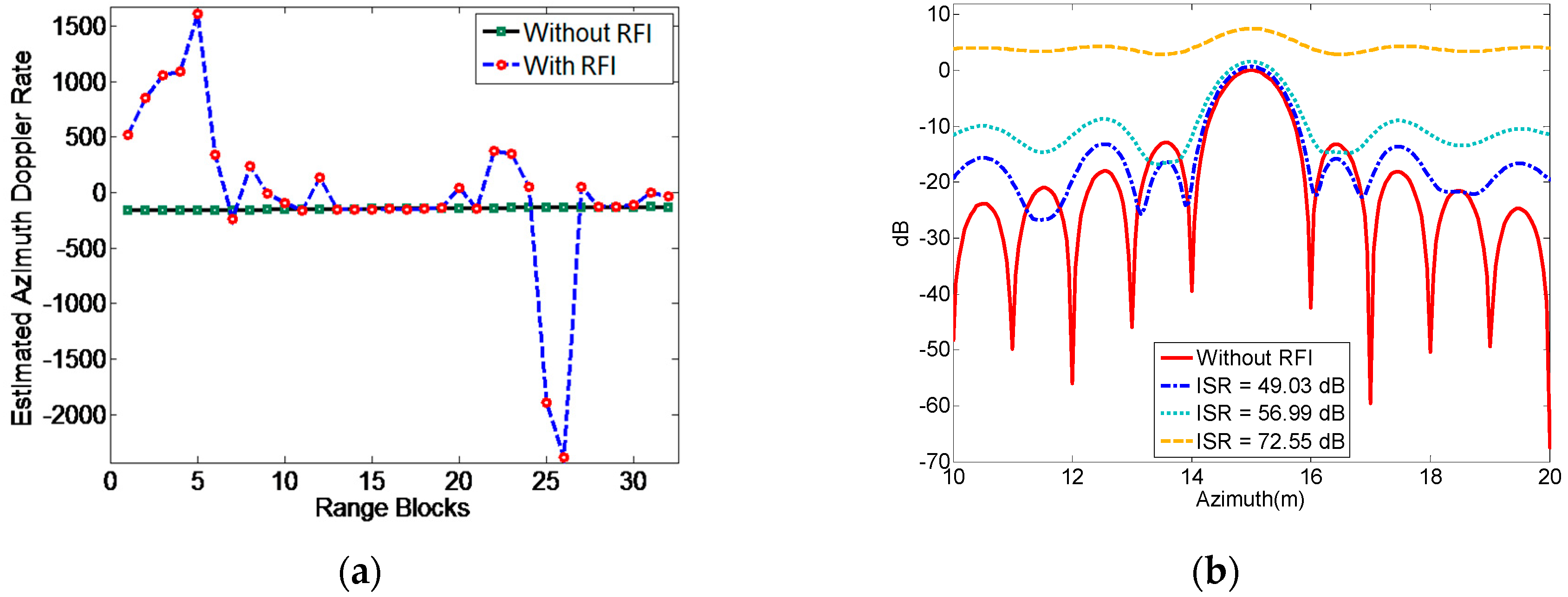
An important feature of SAR is the capability to generate high resolution images. Airborne SAR platforms would introduce significant trajectory deviation and motion errors due to air turbulence. With the absence of enough precise inertial navigation system data, it is required to estimate several critical matched filter parameters directly from the raw data, such as the Doppler centroid and the Doppler modulation rate [7]. The presence of RFI would lead to biased estimates of these parameters. Figure 3a shows an example of estimated azimuth Doppler rate under the cases with and without RFI. In this case, the resulting image will defocus and the quality is severely degraded. Figure 3b illustrates the point target response after matched filtering using biased parameters under different interference to signal ratio (ISR). With the increase of ISR, the side lobe level is raised and the target response is significantly distorted.
1.2.3. Image Interpretation Process
The ultimate goal of SAR imaging is to provide a physical understanding of the illuminated area. The existence of RFI would lead to the amplitude and phase distortion of the imaging data. Intuitively, strong interference would generate haze-like image artifacts or bright lines superimposed on the illuminated area, which lead to inaccurate spatial and radiometric measurements. What is worse, the resulting phase distortion would de-correlate the data, producing inaccurate post-products such as polarimetric descriptor [5], coherence [9], and retrieved biological or physical parameters [10]. Consequently, the RFI hinders the subsequent image interpretation process like target detection, classification, etc.
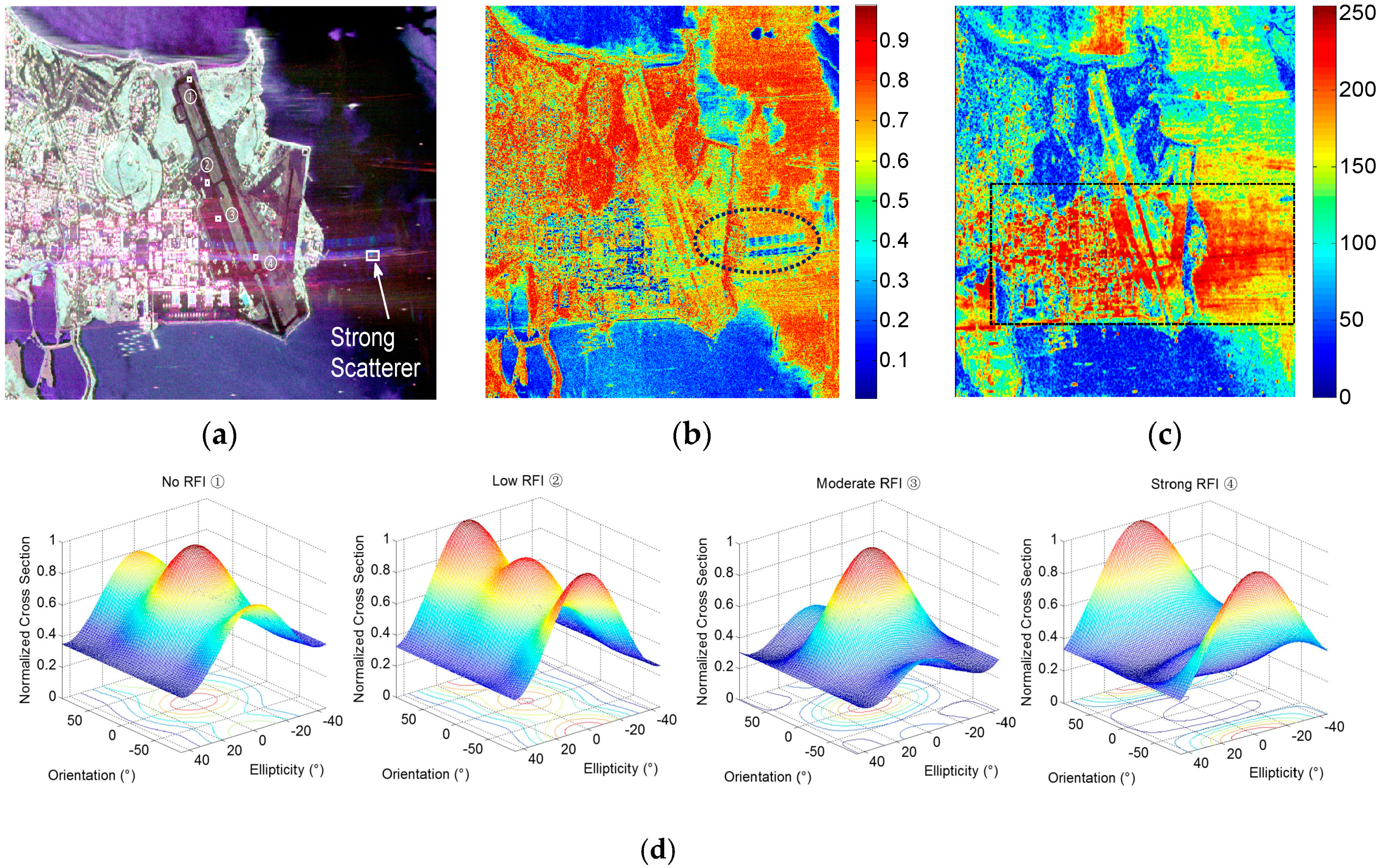
Figure 4 presents an example of National Aeronautics and Space Administration (NASA) Uninhabited Aerial Vehicle Synthetic Aperture Radar (UAVSAR) Hawaii dataset [5]. Obvious RFI stripes are observed and the patterns of the artifacts are very unique, which are not a duplicate of nearby scatterers or areas with strong reflectivity. The patterns are not comparable with the general radiometric artifacts such as the ambiguities, saturation effects, or processing effects. The patterns in the image are bright stripes with curvature, which could be a result of unmatched filtering of the interference. The interference in this dataset may originate from the nearby airport surveillance radar. A category of land cover classification scheme is based on the physical scattering characteristics. The presence of RFI would derive biased estimate of decomposition parameters, and subsequently lead to wrong classification results when using these incorrect parameters. Figure 4b,c shows the entropy and anisotropy parameters obtained by Cloud–Pottier polarimetric decomposition. The regions in dashed lines highlights the anomalies introduced by interference artifacts, where in Figure 4b is mainly the sea surface and in Figure 4c consists of the land, sea surface, and airport runway. Obvious differences are easily observed compared with the nearby regions outside the regions in dashed lines.
Take a further insight, four areas inside the airport runway corresponding to various RFI conditions are selected for illustration, as marked in Figure 4a. They are referred to as No RFI Area ①, Low RFI Area ②, Moderate RFI Area ③, and Strong RFI Area ④, respectively. These areas possess the same scattering mechanisms and should have similar reflectivity. The co-polarized signatures are computed as shown in Figure 4d. These four distributed areas should have the same scattering mechanism with the one under ideal occasion, i.e., low ISR condition. However, with the raise of RFI energy level, the distortion to the shape and intensity of the co-polarized signatures become more severe. Therefore, the distortion of the image amplitude and phase caused by RFI would lead to erroneous polarization signatures. The erroneous polarization signatures would further bias the interpretation of scattering mechanisms.
1.3. Objective and Organization of This Paper
Though many approaches are published for RFI mitigation in SAR data, a thorough summary of current technique status and discussions about future trends is lacking in existing literatures [11,12]. By providing a comprehensive survey of the RFI mitigation techniques applicable for the SAR system, this review can serve as a reference for future work on the implementation of most suitable RFI mitigation schemes for an air-borne or space-borne SAR system.
The review is structured as follows. Section 2 introduces the proactive efforts of frequency allocation and management, illustrating major RFI sources and their interfering mechanism. Typical interference models adopted in existing RFI mitigation techniques are presented as well. In Section 3, a comprehensive literature review of state-of-the-art techniques for RFI mitigation in SAR system is provided. Discussions on the RFI signal models, as well as their pros and cons are given. Further, to deal with the deficiency of current methods, Section 4 outlines possible directions for future development of the field and the final section concludes the review.
2. Interfering Mechanism and Major RFI Sources
2.1. Frequency Allocation and Regulation
The radio spectrum is used by many types of services, ranging from radio and television broadcasting, to wireless phone communication, remote sensing radars, radio astronomy, etc. In order to regulate the use of electromagnetic spectrum in a feasible sharing way, the International Telecommunications Union (ITU) made a lot efforts to propose recommendations, reports, and regulations at the international level [13,14]. According to the frequency allocation rules imposed by the Recommendation ITU-R RS.577-7 [15], the allowable frequency band and bandwidth of a space-borne SAR sensor is listed in Table 1.
In order to avoid conflict to the maximum extent, the radio transmission in each frequency band is categorized into primary and secondary services [16]. Take the P-band and L-band as examples, Figure 5 illustrates the allocated radio services in the vicinity of 432–438 MHz and 1215–1300 MHz. In L-band, the radar remote sensing under the Earth Exploration Satellite Service (EESS) is allocated as a primary basis, which grant it the equal rights with other services sharing the same frequency band including aeronautical radio navigation service (ARNS), radiolocation service (RLS), and radio navigation-satellite service (RNSS). However, SAR system operating in the P-band are allocated as a secondary service with maximum bandwidth of only 6 MHz, and thus are subject to severe geographical and spectral restrictions. This is also the reason that the planned European Space Agency (ESA) Biomass mission has been denied permission to radiate over much of North America and Europe because of perceived interference with the wind profilers and space object tracking radars [17]. The frequency allocation could provide a reliable source for identifying the major RFI sources encountered by a particular SAR sensor operating in a certain frequency band, which will be introduced in the following parts.
2.2. Terrestrial RFI Sources
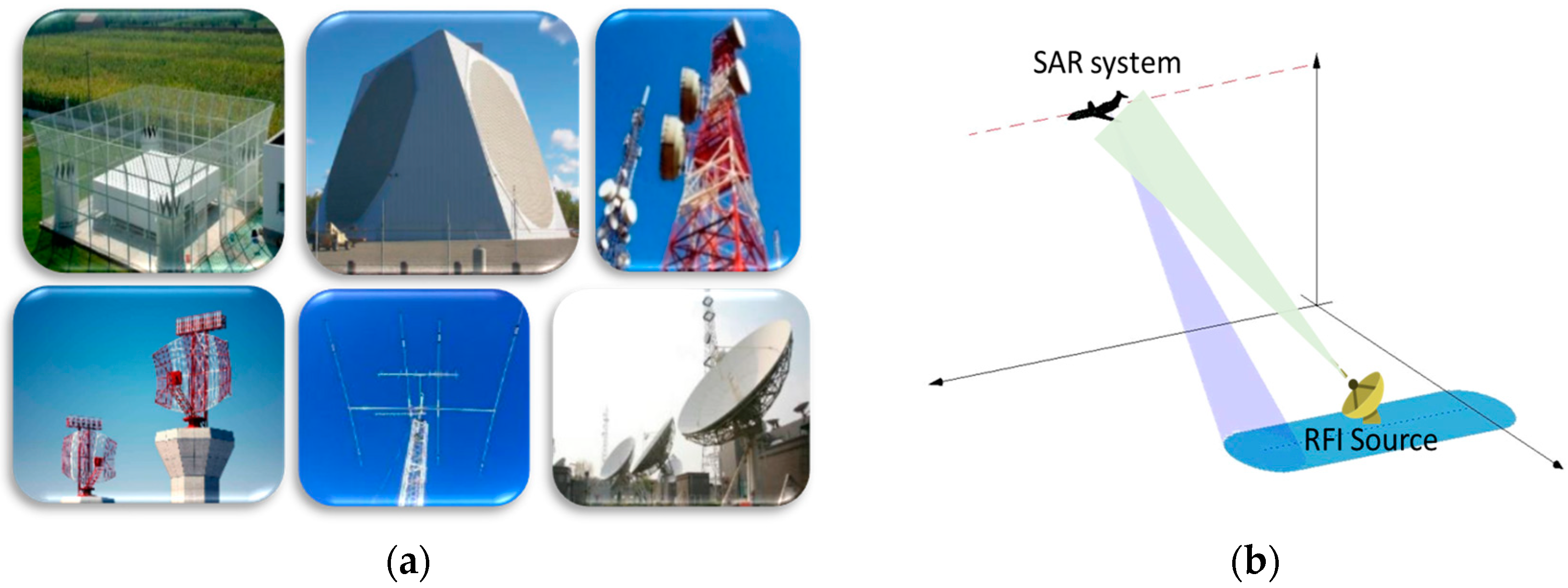
Most of the RFI sources are associated with human activity over land. Terrestrial commercial or industrial radio devices are considered as major RFI sources for SAR, including but not limited to radiolocation radars, wind profiler, telecommunication devices, television networks, amateur radios, etc. Figure 6a illustrates possible terrestrial radio emitters. In recent years, many terrestrial RFI cases have been observed in airborne SAR systems such as AIRSAR [18,19], E-SAR [20], UAVSAR [5], and space-borne SAR systems like PALSAR [21,22] and Sentinel-1 [23,24,25].
Figure 6b illustrates the interfering mechanism between the terrestrial RFI and the SAR system. The detailed derivation for estimating the received RFI power could be found in [26]. Because the terrestrial interference only undergoes a single-way propagation, the received strong RFI signal will raise the noise floor and degrade the SINR significantly. Figure 6c,d provide a comparison of the SAR image with and without the contamination of RFI. This is an airborne SAR dataset acquired in Xi’an, China, with a resolution of 1 m × 1 m. This illuminated scene is a suburban area consisting of apartment buildings and bare lands. The vertical and horizontal directions denote the range and azimuth, respectively. It is shown that the linear patterns with strong energy are very obvious, in which some strong scatterers are also buried under the artifacts. This really hinders further image interpretation process like target detection, land cover classification, etc.
2.3. Space-Borne RFI Sources
Besides the terrestrial RFI sources, there are also few cases with broadcasting signals from other space-borne satellites, such as global navigation satellite systems (GNSSs) constellations, communication satellites or other active remote sensing system, which are regarded as space-borne RFI sources. Figure 7a shows the geometry of interfering mechanism from space-borne RFI source. One possible way is the direct jamming signal to the antenna side-lobe or back-lobe generated by other satellites. According to the analysis for NASA (Soil Moisture Active Passive) SMAP radar, this kind of interference power due to direct reception by back-lobes is non-negligible but tolerable [10].
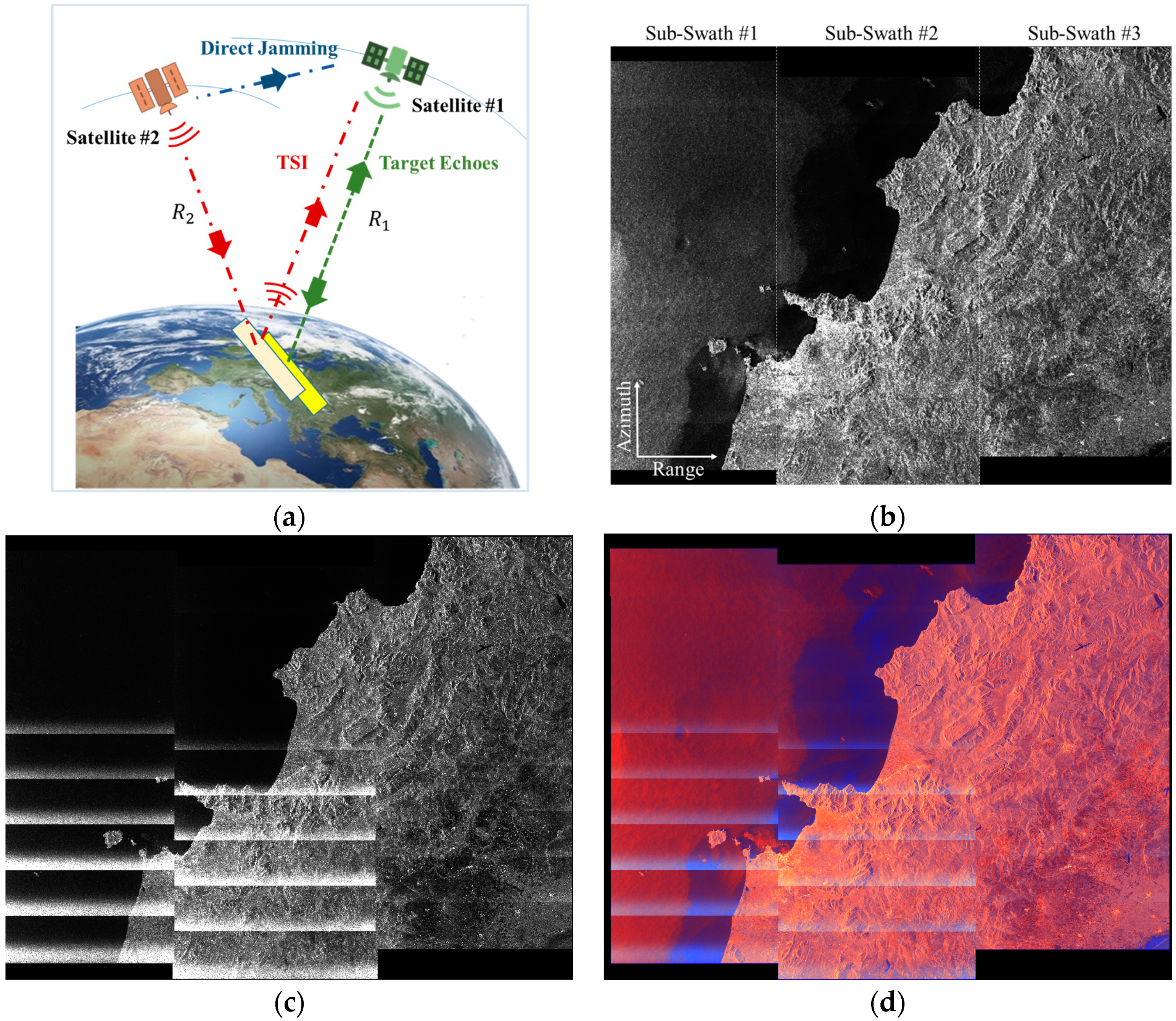
The other is the terrain scattered interference (TSI) reflected off of the earth. When different space-borne systems share nearby illuminated area, strong main lobe-to-main lobe coupling between the two systems may occur [27]. These kinds of reflections off of the earth surface are potentially large when the main beam coincides with a specular point for specular surfaces (lakes, wetlands, etc.). Long duration mutual interference that occurred between Sentinel-1 and the Canadian Radarsat-2 satellite, the Chinese GAOFEN-3 satellite has been reported and investigated [28]. This kind of terrain scattered interference would be more common for future geosynchronous synthetic aperture radar (GEO SAR) system with large imaging swath and frequent revisits, as well as for forthcoming SAR constellations with more frequent occurrences of orbit crossing [29].
For this case, the received RFI signal could not be regarded as a single point-like source anymore, since it undergoes a remodulation by the illuminated area. The estimates of the received RFI power is derived in detail in [29]. Figure 7 shows a TSI example in real measured C-band Sentinel-1 SAR data acquired in Italy in August, 2015. This data is acquired in Terrain Observation by Progressive Scans (TOPS) mode, which consist of three sub-swaths. Each sub-swath is composed of many bursts. The VV, VH, pseudo color coded images are shown in Figure 7b–d, respectively. The horizontal and vertical direction are range and azimuth respectively.
It is shown that many strong stripes with high intensity appeared in VH image, in which produce irregular texture patterns and bury the true echoes of illuminated area. It is caused by simultaneous SAR imaging of the same area from both the Sentinel-1 and Canadian Radarsat-2. The Sentinel-1 and Radarsat-2 both operate using the same central frequency of 5.405 GHz. However, in VV image, the interference pattern is not obvious from visual inspection, and the image amplitude appears not significantly deteriorated by interference effects. This indicates the interference pattern is highly related with the wave polarimetry. For different sub-swaths, the interference situations are also varying. The third sub-swath is less severe than the first and second sub-swaths. This means that RFI characteristics depend strongly on the geographical region of data acquisition. Unwanted interference causes distortion to the amplitude and phase of the echoes. This would definitely produce inaccurate post-products and pose hindrance to subsequent or image interpretation applications like target detection, classification, etc.
2.4. General Signal Model for Typical RFI Sources
For a SAR system, each echo received during a pulse repetition time can be considered as a 1-D time series. Then, an RFI contaminated, complex-valued radar pulse can be modelled as a mixture of target echoes, noise, and interference [12]:
where denotes the complex-valued received signal, denotes the useful target echoes, is the additive noise and is the RFI. denotes the sampling index for range fast-time samples with denoting the number of total samples.
An obvious property of the RFI signals in SAR system is its relatively large power. Owing to the 2-D matched filtering processing, SAR possess large signal processing gain along range and azimuth. Therefore, low power incoherent RFI could be mitigated during the SAR image formation process. However, large-power RFI will still remain in the focused image as visible artifacts or noise [30]. However, if there are a multitude of low-power RFI sources, then the injected noise will be crucial for phase related applications such as SAR interferometry.
The RFI signal can be pulsed or continuous wave. Typically, the type of RFI sources can be categorized into four major classes [1].
(1) Narrow-Band RFI
Narrow-band interference often possess relatively narrow bandwidth than that of the SAR system, while continuous in time relative to the integration time. Typical examples are commercial land-mobile radio and amateur radio. This kind of interfering signal model is well studied in early studies for RFI [31]. In mathematical representation, it can be modeled as a sum of the complex sinusoidal tones, i.e.,:
where , , and denotes the amplitude, carrier frequency, and phase for the l-th interference component, respectively. is the number of RFI sources.
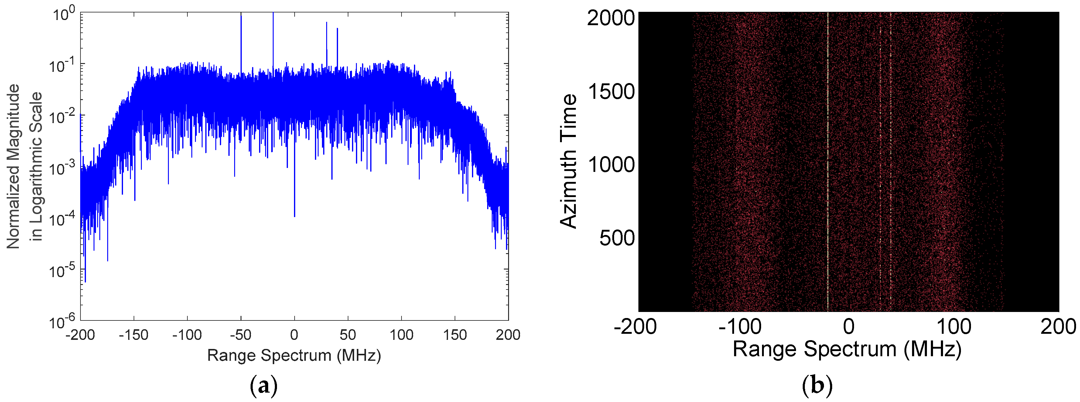
Figure 8 illustrates the range spectra of radar echoes contaminated with narrow band RFI and in range-frequency azimuth-time representation. The data is recorded by a Chinese L-band airborne SAR system transmitting a linear frequency modulated pulse with a bandwidth of 300 MHz. The energy of interferences is concentrated into a few frequency bins, and appear as prominent peaks in the frequency domain and bright lines in the range–frequency azimuth–time representation, respectively. This feature makes it easier to be identified and detected. Generally, the frequencies of the narrow-band RFI are rather stationary.
(2) Pulsed Wide Band RFI
Pulsed wide band RFI are pulsed in time with various pulse repetition time, and the bandwidth is wider than the continuous narrow-band. A common case of such RFI comes from the ground-based radiolocation radar. According to the modulation type, it can be further modeled as two major forms of wide-band interference (WBI), i.e., chirp modulated (CM) WBI and sinusoidal modulated (SM) WBI [8]. In a practical situation, the WBI may not match these two special models perfectly. However, the CM WBI and SM WBI can be considered as two special end examples of a larger family of WBI signatures whose properties are a combination of them.
Mathematically, the CM WBI is modeled as:
where , , and is the amplitude, frequency, and chirp rate of the -th component, respectively. Moreover, the SM WBI can be expressed as:
where , , and are the amplitude, modulation factor, frequency and initial phase of the -th component, respectively.
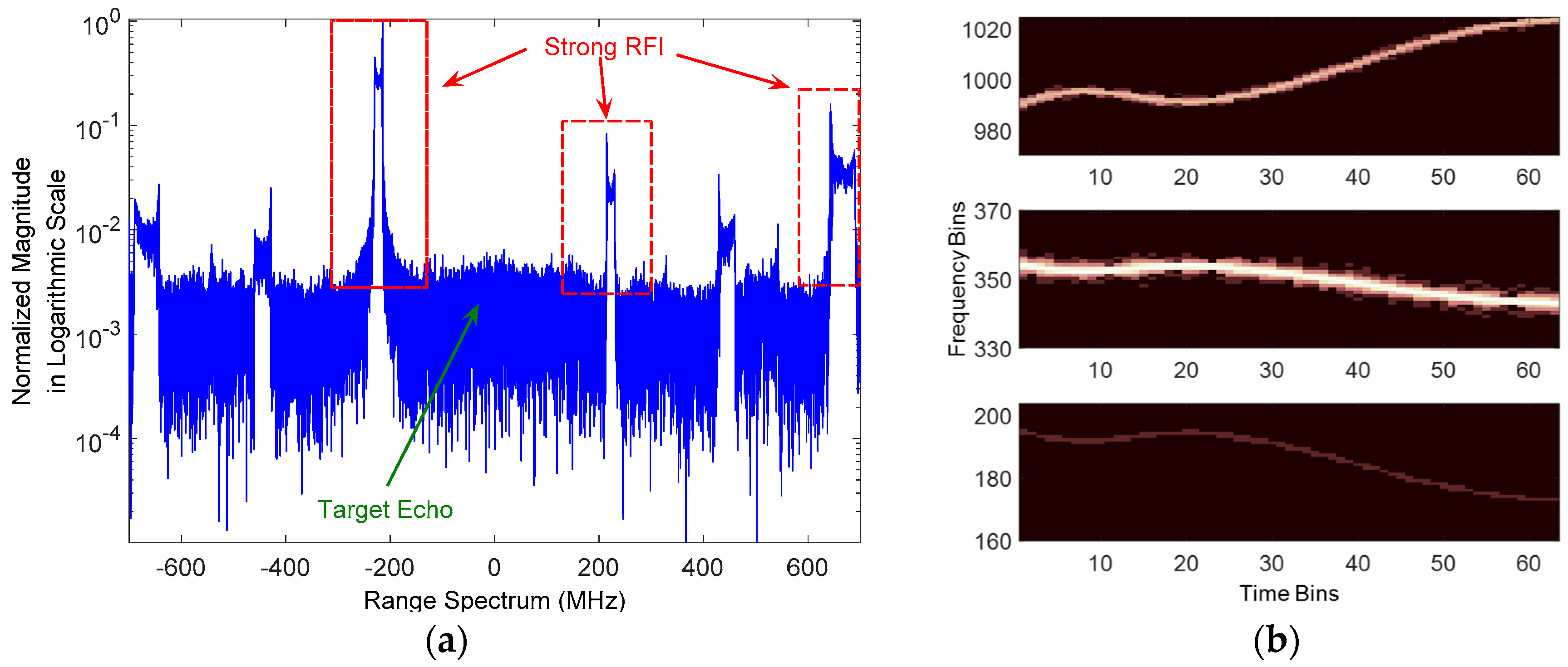
The WBI could not be identified intuitively in time domain, but the interference to signal ratio could be maximized in frequency domain. Figure 9 shows a particular range spectrum of the radar echo with WBI. This data is acquired from a Chinese airborne SAR which operates at X-band. The bandwidth of the transmitted signal is almost 1GHz. From Figure 9a, it is shown that the target echo is contaminated with multiple WBIs with different envelop and bandwidth. Their magnitudes are varying and the strongest one is much larger than that of the target echoes, which makes the target echoes nearly invisible in the range spectrum.
The pulse is transformed onto the time–frequency representation using the short-time Fourier transform (STFT), as shown in Figure 9b. It is straightforward to observe the evolvement of the interference along with the frequency and time, which show that the WBI is highly non-stationary. The time–frequency representation characterizes the nonstationary property very well, in which the energies of WBIs are concentrated into a few frequency bins. The WBI signatures possess properties that are a combination of the CM WBI and SM WBI, which verifies the effectiveness of the model assumption.
(3) Broadband Continuous Wave (CW) RFI
This class depicts the signals that have relatively broad bandwidth due to modulation, and usually are continuous in time, with respect to the integration time. Common cases are broadband communication systems, or coded signals like global navigation satellite system. In this case, they have noise-like characteristics. For example, the digital video broadcasting-terrestrial (DVB-T) signal can be modeled as [32]:
with:
where , , , and denote center frequency, frame number, symbol number and subcarrier number, respectively. denotes the time samples. denotes the subcarrier number corresponding to . denotes the information modulated on the subcarriers. The transmitted signal is organized in frames. is the duration of the guard interval. Each frame has a timed duration of , and consists of Orthogonal Frequency Division Multiplexing (OFDM) symbols. denotes the carrier number, and for the 8K mode.
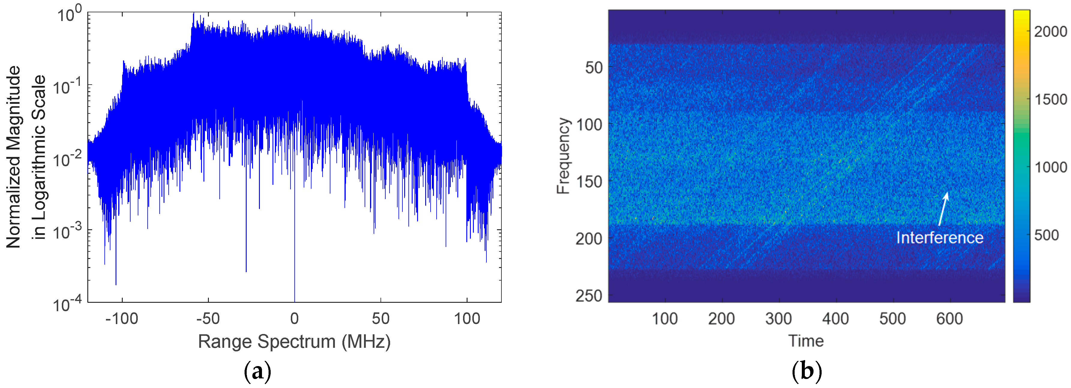
Figure 10a shows a particular echo spectrum corrupted by broadband noise like RFI, and its spectrogram is shown in Figure 10b. The data is acquired by an L-band airborne SAR system with the central frequency of 1.3 GHz and bandwidth of 200 MHz. In Figure 10a, the interference is very strong and have large bandwidth that comparable with the transmitted signal. In the time–frequency domain, the interference overlaps with the target echoes at a large extent, which raise the difficulty of interference detection and separation.
(4) Heterogeneous Environment
For practical SAR system with wide illuminated swath, there will be multiple RFI sources observed simultaneously, either from the main beam or high-gain side lobes. The existence of various encountered RFI sources make it difficult to characterize the RFI problem and the associated solutions.
3. Mitigation Scheme for SAR
The aforementioned narrow band, pulsed wide band, broadband noise like models are very typical models that appeared in current methods. Once the nature and statistical distribution of RFI is known, mitigation techniques can be applied in an attempt to remove it. It should be noted that the data after RFI mitigation is not as good as RFI-free data. The mitigation scheme is applied to alleviate the adverse impact as much as possible. Generally, the basic idea of the RFI mitigation method is manage to find a suitable domain that can maximize the characteristics differences between useful echoes and interference. Then the RFI is either extracted out and excised or filtered directly, while distorting the target echoes as little as possible.
In the following, the state-of the-art RFI mitigation techniques would be introduced and compared thoroughly. An overview comparison is shown in Table 2, and detailed analysis are provided in the following parts.
3.1. Notch Filtering
The intuitive way to perform RFI detection and mitigation is to apply notching filtering in the range spectrum of the radar echoes, which simply excises the samples that are beyond the energy threshold. Since RFI is usually narrowband when compared with the transmitted pulse bandwidth, and presents as narrow spikes in the frequency domain. These spikes are usually many dB stronger than the surrounding signal level. This method is quite simple and efficient and, thus, widely adopted in real airborne SAR and space-borne SAR systems, such as the E-SAR system [20] and Phased Array type L-band Synthetic Aperture Radar (PALSAR) [21]. The ITU-R RS.1749 report also provided a similar strategy suggestion for the Earth exploration-satellite service (EESS) services [33]. Feng et al. [34] proposed a sub-band spectral cancellation method, in which the NBIs are estimated and cancelled by subtracting different range sub-band spectra of the SAR image.
The range spectrum notching filtering should be performed on raw-data whenever possible. When raw data are undisclosed and only focused single look complex (SLC) images are accessible, it is required to remove the remaining RFI from focused data. Reigber et al. [30] and Doerry [35] proposed posteriori filtering methods to excise interference for focused image. Natsuaki et al. [36] proposed a filtering method in the range–time and azimuth–frequency domain utilizing the Doppler difference for intermittently transmitted wideband (ITWB) RFI.
In these cases, the latent fundamental assumption is the RFI is narrow-band, and the signal loss after interference mitigation can be tolerated. However, in some practical cases, the radar echoes may be corrupted by many narrow-band sources or interference with larger bandwidth. The deficiency of notch filtering method is that if the notching exceeds 2% of the waveform, it will induce the degradation in spatial resolution, as well as serious degradation in the waveform side-lobe levels [37]. Since it is an incoherent elimination process, it is not phase preserving. The aperture synthesis in SAR, polarization synthesis in radar polarimetry, and interferogram generation in interferometry SAR (InSAR) would also be affected if large portion of the samples that are notched. To deal with this deficiency, Pinheiro et al. [38] and Musgrove et al. [39,40,41] studied the reconstruction methods based on spectral estimation, with the help of cross-information between coherent data pairs.
3.2. Estimation and Subtraction
An alternative approach to the incoherent notching is the coherent estimation and subtraction. It consists of a coherent estimation and in-phase subtraction of the disturbing sources [42,43,44,45]. The RFI is characterized with a mathematical model like multiple sinusoidal tones [46,47], and regard the wideband signal-plus-system noise as white noise. Then the model parameters of each RFI source such as amplitude, frequency, phase, etc., are estimated under certain criterions including least square, maximum likelihood estimator, Bayesian framework, etc. Further, the interference can be reconstructed by the estimated parameters and coherently subtracted from the contaminated echoes. Theoretically, this kind of method could achieve superior performance. However, this assumption is no longer valid as current RFI sources have complicated digital modulation schemes and are constantly changing. Precise modeling and accurate parameter estimation remain as key issues that degrades the performance. Moreover, the computation burden for iterative estimation is large with multiple sources.
Modelling the interference environment would ideally include information such as the statistics about the density of the interference emitters, the type of such emitters, and their effective radiated power, modulation bandwidth, duty factor, and temporal dependence [48]. For some systems with additional channels or well-designed pulse repetition time, the RFI environment could be dynamically monitored by making use of “sniffer” pulses or “listening beforehand” schemes [10,25].
3.3. Adaptive Filtering
The adaptive filtering methods manage to construct a suitable filter and separate the interference in a certain domain, which can be realized in time, frequency, spatial, polarization, or by multi- domain joint analysis.
3.3.1. Recursive Filter
The most popular adaptive filtering technique is the least-mean-square (LMS) algorithm, which can achieve good compromise for the convergence speed, stability, complexity, and adaptability that are usually required at the same time. The filter coefficients are determined by minimizing the mean square prediction error. In contrast to RFI modeling and estimation, the RFI environment as a whole is modeled as an autoregressive process, narrowband with respect to the radar bandwidth. Hence, most of the RFI signals, narrow and wideband, are estimated in one pass of the adaptive filter. Le et al. constructed a time domain least-mean-square (TDLMS) adaptive filter to address the narrow-band RFI with multiple stationary and non-stationary emitters in wideband NASA AirSAR signals [18,19]. It has also been verified for the E-SAR [49,50,51] and PALSAR system [52]. Its convergence rates are limited by the ratio of the largest and smallest eigenvalues of the autocorrelation matrix of the input signal. To speed up the convergence speed and the computational complexity, a variant of the frequency domain least-mean-square (FDLMS) method is proposed [53,54]. The LMS based methods may be sensitive to nonstationary RFI environment. To improve the capability of fast-tracking time varying signal and noise statistics, Vu et al. proposed to use an adaptive line enhancer (ALE) controlled by the normalized LMS (NLMS) algorithm to eliminate RFI [55]. Li et al. proposed a normalized LMS filter with clipping of strong scatterers to reduce the asymmetric range side-lobes level [56]. To improve the computation efficiency, the Wiener filter is also applied on the SAR data [57,58]. The LMS-based methods suffer from dealing with the wide band interferences and time-varying sources.
3.3.2. Time–Frequency Filtering
Time–frequency representations are commonly used to analyze or characterize non-stationary signals whose energy varies in time and frequency. Based on the analysis of the time–frequency characteristic, an interference suppression filter combined with the constant false alarm rate algorithm is designed in [59]. In [32] and [60], time–frequency reconstruction and the mask technique are proposed to filter the RFI. To achieve super resolution of the time–frequency representation and reduce the signal loss, iterative adaptive approach (IAA) [61,62] features the adaptive RFI estimation and is believed to be more compatible with the time-variant RFI. Su et al. proposed using delay-Doppler iterative decomposition algorithm on the Wigner distribution [63]. Generally, the time–frequency representation is very suitable for differentiating the RFI and SAR echoes, in which the sparse, non-overlapping feature could be maximized for RFI separation and suppression. These methods have large computation burden due to time–frequency transform, and it should be noted that only a reversible time–frequency transform could be used.
3.3.3. Spatial Filtering
Aforementioned techniques are applicable for single channel SAR systems. For modern SAR system, multi antennas or channels are basic configurations, which provides additional degree of freedom to suppress the RFI from spatial directions. Its basic idea is using array beam-forming techniques to orient pattern nulls towards sources of RFI. Rosenberg et al. proposed constrained fast-time space time adaptive processing (STAP) techniques which exploit adaptive beamforming to suppress the interference with minimal distortion to the final image [64,65,66]. Bollian et al. proposed using digital beamforming techniques for the 32-channel EcoSAR system [67,68,69].
The merit of spatial filtering is that it is applicable to the cases that the RFI and SAR signals come from different spatial directions, independent of the RFI signal types. This means that it also works for the most complex broadband CW RFI with the existence of angular difference challenges include the difficulty of accurately estimating the spatial properties of interference, which limits the achieved null depth. In general, an adaptive system using a beam-forming algorithm requires a high INR and is limited to a small number of RFI targets to be tracked during an observation. The RFI sources also need to remain stable and predictable through an observation. These multichannel-based methods are effective to remove interference, but will also increase the complexity of SAR system and cannot be applied to existing mono-channel SARs without an update of the hardware structure.
3.4. Decomposition and Reconstruction
3.4.1. Decomposition
The decomposition method manages to extract the latent components or subspaces corresponding to RFI according to specific difference between RFI and SAR echoes [70], including the power, statistical difference, etc. The eigensubspace projection method uses singular value decomposition (SVD) to separate the large and small singular values into two groups, and then constructs the RFI subspace and signal subspace via the singular vectors corresponding to different singular value groups [71]. Tao et al. extends the eigensubspace projection into the instantaneous spectrum for removing the wide band interference [8]. By making use of the statistical distribution difference, independent component analysis [72] and independent subspace analysis [73] are proposed to extract latent components corresponding to RFI.
Zhou et al. proposed using complex empirical mode decomposition (CEMD) to distinguish the RFI and radar echoes [74]. The essence of the CEMD is to decompose different trends or fluctuations contained in the signal gradually to obtain a series of data sequence with different intrinsic time scales. Elgamel et al. further incorporates the empirical mode decomposition with the fractional Fourier Transform [75]. These methods are data driven and adaptive under specific assumption, but has relatively large computation burden due to iterative optimization. The performance relies on certain prior knowledge of the RFI source.
3.4.2. Reconstruction
Aforementioned extraction or filtering methods would lead to large signal loss to the useful echoes, especially with the presence of long-time duration and wide-band interferences, like the broadband CW RFI introduced in Section 2.3. Originated from the idea of compressed sensing, sparse recovery is a state-of-the-art semi-parametric method for interference suppression, especially in terms of reducing signal distortion. It can be considered as an optimization problem of reconstructing few coefficients with a given dictionary.
Liu et al. utilized the sparsity in range spectrum [76] and in time-frequency domain [77,78] respectively, in which joint sparse recovery for RFI and SAR image are applied to deal with the narrow band and wide band interference. Nguyen et al. adopted similar assumptions for sparse representation and recovery framework based on processing each range-compressed record independently [79]. Lu et al. extends this idea by applying the sparse recovery on the time–frequency plane [80].
Su et al. [81] investigated the robust principal component analysis-based signal separation in time–frequency domain, which exploits the low-rank property of RFI and the sparsity of SAR echoes. To robustly capture the spatial-temporal correlation between signals from neighboring SAR apertures to fully realize the advantages of two-dimensional cross-range processing, the joint sparsity and low-rank models are also proposed [82,83,84,85,86,87]. However, all of these sparse and low rank-based algorithms require a fine-tuning of one or more hyperparameters, and this parameter tuning is not a simple task in practical applications due to lack of prior information on the RFI and radar signals. Huang et al. [88] and Ren et al. [89] provide advanced solutions by proposing hyperparameter-free methods.
With the intrablock correlation (IBC) (i.e., the temporal amplitude correlation among the elements within each block) taken into consideration, block sparse Bayesian learning (BSBL) is more effective to deal with highly underdetermined recovery problem. The modified BSBL-based methods are proposed in [90,91], which is verified to have superior recovery performance in various non-sparse cases.
These recovery methods can successfully reconstruct scattered echoes as long as some low-rank structures or sparsity exists, even if RFI signals are dense or strong. Although these methods have good performance in the RFI separation, they require additional training samples to estimate the RFI structure, and much more storage and computing resources than the conventional filtering techniques, and thus are more suitable for off-line ground processing.
3.5. Discussions
It should be noted that no universal method exists for post mitigating all RFI in SAR data. Current techniques work best for interfering signals that have sparse spectral or temporal or spectral-temporal occupancy with the target echoes. This means these techniques are most effective for narrow band RFI and pulsed wide band RFI, while it is rather difficult to deal with the broadband continuous wave RFI. The effectiveness of any given mitigation technique depends on many factors, including:
- System architecture of the SAR instrument: if SAR has multiple antennas, the sniffing pulse and spatial filtering could be employed. If not, only other signal processing techniques can be applied.
- Configuration or mode for a particular observation: the scanning mode of the data acquisition like stripmap mode, spotlight mode, scan mode, etc., defines the interfering geometry, which determines whether the RFI directs into the SAR receiver from the terrestrial RFI sources or scattered by multi-path from spaceborne RFI sources (as discussed in Section 2.2 and Section 2.3). Different observed modes will lead to different ISR, which is a key factor affecting the algorithm performance.
- Nature of the RFI: for example, whether the RFI source is persistent or intermittent emitted, whether the bandwidth, polarization type is temporally or spatially correlated with the transmitted signal of SAR system, as discussed in Section 2.4.
- The availability of computational resources.
Current mitigation methods depend on expert knowledge for maximizing the difference between the RFI and useful echoes, like energy, statistical difference, etc. During the implementation of these algorithms, some tuned parameters are chosen rather empirically, and only applicable for specified modulation types of interference. However, heterogenous RFI environment would be a challenging task, where various RFI types could be encountered simultaneously. Mitigation techniques should be adaptive, practical, and applicable in routine operations, thus minimizing the expert inference as much as possible.
4. Suggestions for Future Trends
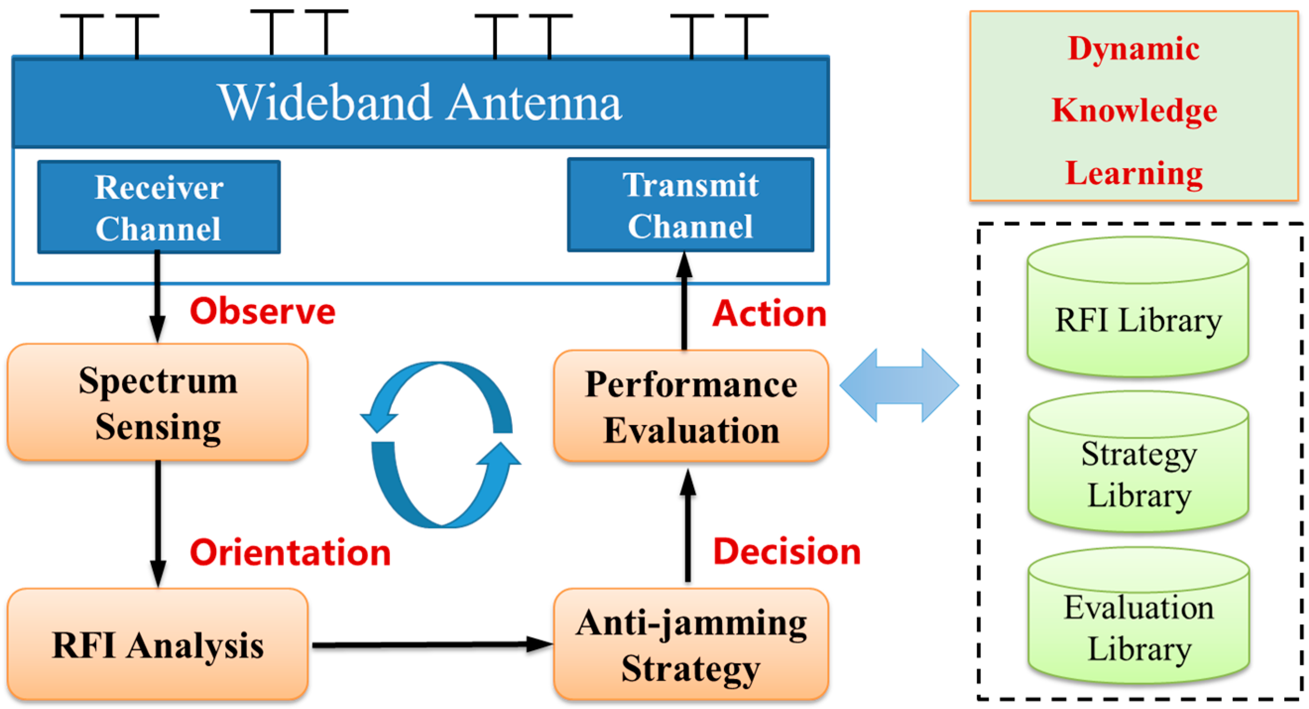
Motivated by the challenges presented in Section 3.5, and follows on the flow of the received signal and according to the Observation-Orientation-Decision-Action (OODA) rule, we think future trends for the RFI mitigation techniques can be summarized into three keywords: Cognitive, Integrated, and Adaptive. These three aspects form an integral system, and support each other for improving the RFI-rejection performance. Figure 11 depicts an assumed system architecture for future SAR systems incorporating the RFI mitigation capability. The whole flow is a dynamic, learning-based process involving long-term planning, decision-making correction, and long-term incremental learning.
4.1. Cognitive
Cognitive means that the SAR system should be able to sense the complex electromagnetic environment both dynamically and quickly, with the advancement of cognitive technology [92,93]. In a previous operating SAR system, the RFI issues may not be regarded as a critical issue and without careful consideration in the system design phase. For the signal processing techniques, not all the encountered RFI effects could be mitigated in post processing. The RFI mitigation technology cannot be regarded as a standalone fix for the external RFI problems experienced by present day and future SAR systems. It is better that the RFI environment to be mitigated are clearly understood before sensor deployment, flight, or launch [26], and thus corresponding effective mitigation could be developed. For example, the future planned Biomass system have analyzed the potential interference sources and developed ground processing software for RFI mitigation [94,95]. As international pioneers in SAR system, NASA and the Japan Aerospace Agency (JAXA) have rich experience on RFI and integrated the RFI mitigation into the earlier development stage of spaceborne radar systems [10], [21]. When the SAR system becomes operational in orbit, it can still monitor the RFI environment by introducing the design of additional sniffing channels. This part represents the dynamic knowledge learning process (as shown in Figure 11), and acts as a fundamental role for the other two parts. By learning from the real RFI scenarios, more variety of refined signal models could be established (compared with those introduced in Section 2), which is beneficial for performance improvement.
4.2. Integrated
As RFI environment is evolving temporally and varying geographically, the characterization and mitigation are not easy tasks. No single technique can address all possible RFI scenarios for SAR observations. To better improve the anti-jamming capability and prevent being RFI-affected, integrated means that the RFI mitigation should be performed by combing different aspects of techniques ranging from the transceiver system level to signal processing level.
From the transceiver system level, the sniffing pulse can be exploited for RFI pre-detection and monitoring, with the cost of reducing the pulse repetition frequency of transmitted waveform. For electronically scanned SAR systems, the digital beamforming techniques could be employed to create antenna null steering for side-lobe RFI rejection, while not applicable to deal with main-lobe jamming. Theoretically, for forthcoming SAR constellations or distributed SAR systems, the synthetic large aperture could narrow the nulling beam width and improve the jamming rejection performance. However, due to its long distance between array elements, the far field assumption will be violated and the traditional digital beamforming is not applicable. In this case, more complex effort should be made to realize near-field beamforming and alleviate grating lobe effect [96,97]. Future multiple-input and multiple-output (MIMO) SAR system could provide more waveform diversity ability to maneuver in time, frequency, space, and polarization, and thus have the potential to improve the anti-jamming capability [98].
If the RFI signal emitted from the same direction with the SAR echoes and recorded by the receiver, the post-processing mitigation is then applied. This energy can be excised with a variety of advanced signal processing techniques as introduced in Section 3. For more general and heterogeneous environment, the RFI entering the main-lobe could be mitigated from the signal processing level by performing joint domain analysis. By jointly exploiting the characteristics among time, frequency, spatial, polarization, code, and power domain, the difference between RFI and target echoes can be characterized more accurately, and thus improve the mitigation performance by using tensor-based multilinear analysis [99].
By integrating the methods ranging from the transceiver system level to signal processing level, it can overcome the limitations of the applicability to various RFI signal types as listed in Table 2. Each part could share the burden for improving the overall RFI mitigation performance to a higher level.
4.3. Adaptive
Adaptive requires the SAR system have the capability to adopt the optimal strategy according to the dynamic change of the RFI environment. Low resolution SMAP system with 1 MHz signal bandwidth adopts an agile frequency selection scheme to avoid the interference in various time and regions. This may not be applicable for other high-resolution systems. Transmitted waveform could also be adaptively designed according to changing RFI environment [100].
On the other hand, the artificial learning techniques have proved very successful for various applications in recent years. Initial research show that the introduction of advanced artificial intelligent techniques such as deep learning network perform rather good for interference suppression [101,102,103,104]. After finishing the off-line training step of the artificial neural network from the big data, the on-line detection and mitigation could be realized in a quite efficient way [104]. Its key challenge is that the training database should be large enough to include the RFI cases as much as possible, and thus the trained artificial neural network could capture the essential feature explicitly. This could be achieved by combing the cognitive techniques mentioned in Section 4.1, which makes the long-term accumulation of RFI samples and incremental learning of the RFI environment possible. Therefore, in the foreseeable future, more works about applying the intelligent learning methods for RFI mitigation in SAR system will emerge.
5. Conclusions
In recent years, RFI is increasing and now represents one of the major threats to scientific uses of the spectrum. The awareness of the adverse effect of RFI is growing over the years, especially for quantitative remote sensing applications where highly sensitive measurements are required. Its adverse impacts lie on many aspects ranging from raw data collection, image formation, and subsequent interpretation process. In this review, we provide a comprehensive survey of the state-of the-art techniques for RFI mitigation in SAR systems, which can serve as a reference for future work on the implementation of most suitable RFI mitigation scheme for an airborne or space-borne SAR system.
The role of frequency management and allocation is very important and requires to be further enhanced. In the future, more intelligent regulation is required, which means the electromagnetic spectrum are more efficient and dynamically controlled. Scientific interests must be actively engaged to satisfy the science needs.
Although an increasing variety of successful mitigation options are available, there is a tradeoff between efficiency and accuracy when adopting the post-processing methods. Notch filtering and LMS filtering are adopted widely for its simplicity and efficiency, and is very suitable for on-board quick processing. Other refined mitigation schemes such as time-frequency domain joint filtering and sparse recovery are possible candidates for off-line ground processing due to their relatively large computational complexity. In particular, on-line real-time data processing may be preferred in a variable RFI environment, while special measures such as reference antennas and spatial filtering may be preferred for known and fixed sources of RFI. Existing post-processing mitigation schemes can be applied on the raw data or SLC data. Nevertheless, raw-data filtering is still a superior approach that should be considered whenever possible.
Moreover, more attention should be paid on the evaluation of mitigation performance. It is intuitively to focus on the strong interference and its resulting obvious distortion to amplitude. However, lower power interference could also not be omitted, because its impact on phase could be detrimental. For many SAR systems, mitigating interference artifacts from imagery is not the only concern, and the phase preserving performance is important. Therefore, the chosen interference mitigation scheme must also guarantee successful restoration of the quality of the second order products, as it is highly related with the post image products, e.g., interferometric coherence, polarimetric descriptors, etc.
In the foreseeable future, the RFI will remain as a great challenge to accurate remote sensing by active sensor like SAR. Current RFI mitigation technology appears to offer significant benefits to SAR remote sensing, but more refined characterization and mitigation work remains to be developed that is practical and applicable in routine operations. The development of a common set of standardized metrics connecting RFI levels to science product accuracies would be useful in assessing the costs of observing with increasing levels of RFI.
Author Contributions
Conceptualization, M.T., L.W.; methodology, M.T., J.S., Y.H.; formal analysis, J.S., and Y.H.; resources, J.S., and Y.H.; data curation, M.T., J.S., Y.H.; writing—original draft preparation, M.T., J.S.; writing—review and editing, M.T.; supervision, L.W.; funding acquisition, M.T., J.S., L.W.
Funding
This work was funded by National Nature Science Foundation of China (NSFC) under Grants 618013906, 61701414 and 61901112. Also partly supported by the Science, Technology, and Innovation Commission of Shenzhen Municipality under Grant JCYJ20170306154716846 and JCYJ20170815154325384. This work is also supported by Postdoctoral Innovation Talent Support Program under grant BX201700199, by China Postdoctoral Science Foundation under grant 2017M623240 and 2018M631123, and by Young Talent fund of University Association for Science and Technology in Shaanxi, China under grant 20180102. It is also partly supported by the Natural Science Foundation of Jiangsu Province BK20190330.
Conflicts of Interest
The authors declare no conflict of interest.
References
- National Academies of Sciences, Engineering, and Medicine. A Strategy for Active Remote Sensing Amid Increased Demand for Radio Spectrum; National Academies Press: Washington, DC, USA, 2015. [Google Scholar]
- Spencer, M.; Ulaby, F. Spectrum issues faced by active remote sensing. IEEE Geosci. Remote Sens. Mag. 2016, 4, 40–45. [Google Scholar] [CrossRef]
- De Matthaeis, P.; Oliva, R.; Soldo, Y. Spectrum management and its importance for microwave remote sensing. IEEE Geosci. Remote Sens. Mag. 2018, 6, 17–25. [Google Scholar] [CrossRef]
- IEEE FARS Technical Committee. Database of Frequency Allocations for Microwave Remote Sensing and Observed Radio Frequency Interference. Available online: http://grss-ieee.org/microwave-interferers/ (accessed on 13 August 2019).
- Tao, M.; Zhou, F.; Zhang, Z. Characterization and Mitigation of Radio Frequency Interference in PolSAR Data. Radio Sci. 2017, 52, 1405–1418. [Google Scholar] [CrossRef]
- NTIA Report TR-06-444. Effects of RF Interference on Radar Receivers. 2006. Available online: https://its.bldrdoc.gov/publications/details.aspx?pub=2481 (accessed on 30 June 2019).
- Zhang, L.; Qiao, Z.; Xing, M.; Yang, L.; Bao, Z. A robust motion compensation approach for UAV SAR imagery. IEEE Trans. Geosci. Remote Sens. 2012, 50, 3202–3218. [Google Scholar] [CrossRef]
- Tao, M.; Zhou, F.; Zhang, Z. Wideband Interference Mitigation in High-Resolution Airborne Synthetic Aperture Radar Data. IEEE Trans. Geosci. Remote. Sens. 2015, 54, 74–87. [Google Scholar] [CrossRef]
- Xu, H.; Wu, Z.; Liu, W.; Li, J.; Feng, Q. Analysis of the effect of interference on InSAR. IEEE Sens. J. 2015, 15, 5659–5668. [Google Scholar] [CrossRef]
- Spencer, M.W.; Chen, C.W.; Ghaemi, H.; Chan, S.F.; Belz, J.E. RFI characterization and mitigation for the SMAP radar. IEEE Trans. Geosci. Remote Sens. 2013, 51, 4973–4982. [Google Scholar] [CrossRef]
- Doerry, A.W. Comments on radar interference sources and mitigation techniques. In Proceedings of the SPIE 2015 Defense & Security Symposium, Baltimore, MD, USA, 20 April 2015; pp. 1–8. [Google Scholar]
- Nguyen, L.H.; Tran, T.D. A comprehensive performance comparison of RFI mitigation techniques for UWB radar signals. In Proceedings of the International Conference on Acoustics, Speech, and Signal Process, New Orleans, LA, USA, 5–9 March 2017; pp. 3086–3090. [Google Scholar]
- Griffiths, H.; Cohen, L.; Watts, S.; Mokole, E.; Baker, C.; Wicks, M.; Blunt, S. Radar spectrum engineering and management: Technical and regulatory issues. Proc. IEEE 2015, 108, 85–102. [Google Scholar] [CrossRef]
- Misra, S.; de Matthaeis, P. Passive remote sensing and radio frequency interference (RFI): An overview of spectrum allocations and RFI management algorithms. IEEE Geosci. Remote Sens. Mag. 2014, 2, 68–73. [Google Scholar] [CrossRef]
- ITU-R Recommendation RS.577-7. Frequency Bands and Required Bandwidths Used for Spaceborne Active Sensors Operating in the Earth Exploration-Satellite (Active) and Space Research (Active) Services. 2009. Available online: https://www.itu.int/rec/R-REC1-RS.577/en (accessed on 30 June 2019).
- National Academies of Sciences, Engineering, and Medicine. Spectrum Management for Science in the 21st Century; The National Academies Press: Washington, DC, USA, 2010. [Google Scholar]
- Committee on Scientific Use of the Radio Spectrum. Handbook of Frequency Allocations and Spectrum Protection for Scientific Uses, 2nd ed.; The National Academies Press: Washington, DC, USA, 2015. [Google Scholar]
- Le, C.; Hensley, S.; Chapin, E. Adaptive Filtering of RFI in Wideband Radars Using the LMS Algorithms. Part I: The TDLMS Adaptive Filter. 1998. Available online: http://citeseerx.ist.psu.edu/viewdoc/summary?doi=10.1.1.596.393 (accessed on 18 October 2019).
- Le, C.; Hensley, S. RFI Removal from AirSAR Polarimetric Data; In Proceedings of the JPL AIRSAR Workshop, Pasadena, California, USA, 4–6 March 2002; pp. 1–4. [Google Scholar]
- Buckreuss, S.; Horn, R. E-SAR P-band SAR subsystem design and RF-Interference suppression. In Proceedings of the IEEE International Geoscience Remote Sensing Symposium, Seattle, WA, USA, 6–10 July 1998; pp. 1–4. [Google Scholar]
- Meyer, F.J.; Nicoll, J.B.; Doulgeris, A.P. Correction and characterization of radio frequency interference signatures in L-band synthetic aperture radar data. IEEE Trans. Geosci. Remote Sens. 2013, 51, 4961–4972. [Google Scholar] [CrossRef]
- Natsuaki, R.; Motohka, T.; Tadono, T.; Suzuki, S. Polarimetric characteristics of temporarily coherent RFI in ALOS-2 PALSAR-2. In Proceedings of the IEEE International Geoscience Remote Sensing Symposium, Fortworth, TX, USA, 23–28 July 2017; pp. 3155–3158. [Google Scholar]
- Monti-Guarnieri, A.; Giudici, D.; Recchia, A. Identification of C-Band Radio Frequency Interferences from Sentinel-1 Data. Remote Sens. 2017, 9, 1183. [Google Scholar] [CrossRef]
- Leng, X.; Ji, K.; Zhou, S.; Xing, X.; Zou, H. Discriminating Ship from Radio Frequency Interference Based on Noncircularity and Non-Gaussianity in Sentinel-1 SAR Imagery. IEEE Trans. Geosci. Remote Sens. 2019, 57, 352–363. [Google Scholar] [CrossRef]
- Recchia, A.; Giudici, D.; Piantanida, R.; Franceschi, N.; Monti-Guarnieri, A.; Miranda, N. On the effective usage of Sentinel-1 noise pulses for denoising and RFI identification. In Proceedings of the 12th European Conference on Synthetic Aperture Radar, Aachen, Germany, 4–7 June 2018; pp. 1–4. [Google Scholar]
- Li, Y.; Guarnieri, A.M.; Hu, C.; Rocca, F. Performance and requirements of GEO SAR systems in the presence of radio frequency interferences. Remote Sens. 2018, 10, 82. [Google Scholar] [CrossRef]
- Santamaria, C.; Alvarez, M.; Greidanus, H.; Syrris, V.; Soille, P.; Argentieri, P. Mass Processing of Sentinel-1 Images for Maritime Surveillance. Remote. Sens. 2017, 9, 678. [Google Scholar] [CrossRef]
- S-1 Mission Performance Center. Sentinel-1 Long Duration Mutual Interference. 2018. Available online: http://sentinel.esa.int/documents/247904/2142675/ (accessed on 30 June 2019).
- Leanza, A.; Manzoni, M.; Monti-Guarnieri, A.; Di Clemente, M. LEO to GEO-SAR Interferences: Modelling and Performance Evaluation. Remote. Sens. 2019, 11, 1720. [Google Scholar] [CrossRef]
- Reigber, A.; Ferro-Famil, L. Interference suppression in synthesized SAR images. IEEE Geosci. Remote Sens. Lett. 2005, 2, 45–49. [Google Scholar] [CrossRef]
- Yang, L.; Zheng, H.; Feng, J.; Li, N.; Chen, J. Detection and suppression of narrow band RFI for synthetic aperture radar imaging. Chin. J. Aeronaut. 2015, 28, 1189–1198. [Google Scholar] [CrossRef] [Green Version]
- Zhao, T.; Zhang, Y.; Yang, L.; Dong, Z.; Liang, D. The RFI suppression method based on STFT applied to SAR. Prog. Electromagn. Res. M 2013, 31, 171–188. [Google Scholar] [CrossRef]
- ITU-R Recommendation RS.1749. Mitigation Technique to Facilitate the Use of the 1 215-1 300 MHz Band by the Earth Exploration-Satellite Service (Active) and the Space Research Service (Active). 2006. Available online: https://www.itu.int/rec/R-REC-RS.1749/en (accessed on 30 June 2019).
- Feng, J.; Zheng, H.; Deng, Y.; Gao, D. Application of subband spectral cancellation for SAR narrow-band interference suppression. IEEE Geosci. Remote Sens. Lett. 2012, 9, 190–193. [Google Scholar] [CrossRef]
- Doerry, A.W. Apodized RFI Filtering of Synthetic Aperture Radar Images; Sandia National Laboratories: Albuquerque, NM, USA, 2014. [Google Scholar]
- Natsuaki, R.; Motohka, T.; Watanabe, M.; Shimada, M. An autocorrelation-based radio frequency interference detection and removal method in azimuth-frequency domain for SAR image. IEEE J. Sel. Top. Appl. Earth Obs. 2017, 10, 5736–5751. [Google Scholar] [CrossRef]
- Davis, M. Frequency allocation challenges for ultra-wideband radars. IEEE Aerosp. Electron. Syst. Mag. 2013, 28, 12–18. [Google Scholar] [CrossRef]
- Pinheiro, M.; Rodrigues-Cassola, M.; Prats-Iraoloa, P.; Reigber, A.; Krieger, G.; Moreira, A. Reconstruction of coherent pairs of synthetic aperture radar data acquired in interrupted mode. IEEE Trans. Geosci. Remote Sens. 2015, 53, 1876–1893. [Google Scholar] [CrossRef]
- Musgrove, C.; West, J.C. Application of equalization notch to improve synthetic aperture radar coherent data products. Proc. SPIE 2015, 9461, 94610. [Google Scholar]
- Musgrov, C.; West, J.C. Mitigating effects of missing data for SAR coherent images. IEEE Trans. Aerosp. Electron. Syst. 2017, 53, 716–721. [Google Scholar] [CrossRef]
- Musgrov, C.; West, J.C. Replacing missing data between airborne SAR coherent image pairs. IEEE Trans. Aerosp. Electron. Syst. 2017, 53, 3150–3158. [Google Scholar] [CrossRef]
- Nguyen, L.; Soumekh, M. Suppression of radio frequency interference (RFI) for synchronous impulse reconstruction ultra-wideband radar. Proc. SPIE 2005, 5808, 178–184. [Google Scholar]
- Miller, T.R. Radio frequency interference suppression for foliage penetrating radar imaging. Ph.D. Thesis, Ohio State University, Columbus, OH, USA, 1994. [Google Scholar]
- Yi, J.; Wan, X.; Cheng, F.; Gong, Z. Computationally efficient RF interference suppression method with closed-form maximum likelihood estimator for HF surface wave over-the-horizon radars. IEEE Trans. Geosci. Remote Sens. 2013, 51, 2361–2372. [Google Scholar] [CrossRef]
- Ojowu, O., Jr.; Li, J. RFI suppression for synchronous impulse reconstruction UWB radar using RELAX. Int. J. Remote Sens. Appl. 2013, 3, 33–46. [Google Scholar]
- Cazzaniga, G.; Guarnieri, A.M. Removing RF interferences from P-band airplane SAR data. In Proceedings of the 1996 International Geoscience and Remote Sensing Symposium, Lincoln, NE, USA, 31 May 1996; pp. 1–4. [Google Scholar]
- Miller, T.; Potter, L.; McCorkle, J. RFI suppression for ultra wideband radar. IEEE Trans. Aerosp. Electron. Syst. 1997, 33, 1142–1156. [Google Scholar] [CrossRef]
- Lord, R.T. Radio Frequency Interference Suppression Applied to Synthetic Aperture Radar Data. In Proceedings of the XXVIIIth General Assembly of International Union of Radio Science, New Delhi, India, 23–29 October 2005; pp. 1–4. [Google Scholar]
- Potsis, A.; Uzunoglou, N.; Frangos, P.; Horn, R.; Lamprecht, K. Analysis of P-Band Synthetic Aperture Radar for Airborne and Spaceborne Applications. 2000. Available online: https://apps.dtic.mil/dtic/tr/fulltext/u2/p010835.pdf (accessed on 18 October 2019).
- Potsis, A.; Reigber, A.; Papathanassiou, K.P. A phase preserving method for RF interference suppression in P-bannd synthetic aperture radar interferometric data. In Proceedings of the IEEE 1999 International Geoscience and Remote Sensing Symposium, Hamburg, Germany, 28 June–2 July 1999; pp. 1–4. [Google Scholar]
- Lord, R.T.; Inggs, M.R. Efficient RFI suppression in SAR using LMS adaptive filter integrated with range/Doppler algorithm. Electron. Lett. 1999, 35, 629–630. [Google Scholar] [CrossRef]
- Rosen, P.A.; Hensly, S.; Le, C. Observations and mitigation of RFI in ALOS PALSAR SAR data: Implications for the DESDYNI mission. In Proceedings of the IEEE Radar Conference, Rome, Italy, 26–30 May 2008; pp. 1–4. [Google Scholar]
- Luo, X.; Ulander, L.; Askne, J.; Smith, G.; Frölind, P.-O. RFI suppression in ultra-wideband SAR systems using LMS filters in frequency domain. Electron. Lett. 2001, 37, 241–243. [Google Scholar] [CrossRef]
- Harcke, L.J.; Le, C.T. AirMoss P-band RF interference experience. In Proceedings of the IEEE Radar Conference, Cincinnati, OH, USA, 19–23 May 2014; pp. 1–4. [Google Scholar]
- Vu, V.T.; Sjogren, T.K.; Gustavsson, M.I.P.L.H.A.; Ulander, L. RFI suppression in ultrawideband SAR using an adaptive line enhancer. IEEE Geosci. Remote Sens. Lett. 2010, 7, 694–698. [Google Scholar] [CrossRef]
- Li, Y.; Li, X.; Zhou, Z. Side-lobe reduction for radio frequency interference suppression via clipping of strong scatterers. IEEE Geosci. Remote Sens. Lett. 2016, 13, 1178–1182. [Google Scholar] [CrossRef]
- Lamont-Smith, T.; Hill, R.D.; Hayward, S.; Yates, G.; Blake, A. Filtering approaches for interference suppression in low-frequency SAR. IET Radar Sonar and Navig. 2016, 153, 338–344. [Google Scholar] [CrossRef]
- Song, Y.; Hu, J.; Dai, Y.; Jin, T.; Zhou, Z. Estimation and mitigation of time-variant RFI in low-frequency ultra-wideband radar. IEEE Geosci. Remote Sens. Lett. 2018, 15, 409–413. [Google Scholar] [CrossRef]
- Zhang, S.; Xing, M.; Guo, R.; Zhang, L.; Bao, Z. Interference Suppression Algorithm for SAR Based on Time–Frequency Transform. IEEE Trans. Geosci. Remote. Sens. 2011, 49, 3765–3779. [Google Scholar] [CrossRef]
- Li, D.; Liu, H.; Yang, L. Efficient time-varying interference suppression method for synthetic aperture radar imaging based on time-frequency reconstruction and mask technique. IET Radar Sonar Navig. 2015, 9, 827–834. [Google Scholar] [CrossRef]
- Liu, Z.; Liao, G.; Yang, Z. Time variant RFI suppression for SAR using iterative adaptive approach. IEEE Geosci. Remote Sens. Lett. 2013, 10, 1424–1428. [Google Scholar] [CrossRef]
- Yang, Z.; Du, W.; Liu, Z.; Liao, G. WBI suppression for SAR using iterative adaptive method. IEEE J. Sel. Topics Appl. Earth Obs. Remote Sens. 2016, 9, 1008–1014. [Google Scholar] [CrossRef]
- Su, J.; Tao, H.; Tao, M. Time-varying SAR interference suppression based on delay-Doppler iterative decomposition algorithm. Remote Sens. 2018, 10, 1491. [Google Scholar] [CrossRef]
- Rosenberg, L.; Gray, D.A. Anti-jamming techniques for multichannel SAR imaging. IET Radar Sonar Navig. 2006, 153, 234–242. [Google Scholar] [CrossRef] [Green Version]
- Rosenberg, L. Multichannel Synthetic Aperture Radar. Ph.D. Thesis, School of Electrical & Electronic Engineering, University of Adelaide, Adelaide, Australia, 2007. [Google Scholar]
- Rosenberg, L.; Gray, D.A. Constrained Fast-Time STAP for interference suppression in multichannel SAR. IEEE Trans. Aerosp. Electron. Syst. 2013, 49, 1792–1805. [Google Scholar] [CrossRef]
- Osmanoglu, B.; Rincon, R.F.; Lee, S.; Fatoyinbo, T.; Bollian, T. Radio frequency interference detection and mitigation techniques using data from EcoSAR 2014 flight campaign. In Proceedings of the EUSAR 2016: 11th European Conference on Synthetic Aperture Radar, Hamburg, Germany, 6–9 June 2016; pp. 1–4. [Google Scholar]
- Bollian, T.; Osmango, B.; Rincon, R.F.; Lee, S.; Fatoyinbo, T.E. Detection and geolocation of P-band radio frequency interference using EcoSAR. IEEE J. Sel. Topics Appl. Earth Obs. Remote Sens. 2017, 11, 3608–3616. [Google Scholar] [CrossRef]
- Bollian, T.; Osmanoglu, B.; Rincon, R.; Lee, S.-K.; Fatoyinbo, T. Adaptive Antenna Pattern Notching of Interference in Synthetic Aperture Radar Data Using Digital Beamforming. Remote. Sens. 2019, 11, 1346. [Google Scholar] [CrossRef]
- Zhou, F.; Tao, M. Research on Methods for Narrow-Band Interference Suppression in Synthetic Aperture Radar Data. IEEE J. Sel. Top. Appl. Earth Obs. Remote. Sens. 2015, 8, 3476–3485. [Google Scholar] [CrossRef]
- Zhou, F.; Wu, R.; Xing, M.; Bao, Z. Eigen subspace-based filtering with application in narrowband interference suppression for SAR. IEEE Geosci. Remote Sens. Lett. 2007, 4, 75–79. [Google Scholar] [CrossRef]
- Zhou, F.; Tao, M.; Bai, X.; Liu, J. Narrow-band interference suppression for SAR based on independent component analysis. IEEE Trans. Geosci. Remote Sens. 2015, 51, 4952–4960. [Google Scholar] [CrossRef]
- Tao, M.; Zhou, F.; Liu, J.; Liu, Y.; Zhang, Z.; Zhang, Z.; Bao, Z. Narrow-band interference mitigation for SAR using independent subspace analysis. IEEE Trans. Geosci. Remote Sens. 2014, 52, 5289–5301. [Google Scholar]
- Zhou, F.; Xing, M.; Bai, X.; Sun, G.; Bao, Z. Narrowband interference suppression for SAR based on complex empirical mode decomposition. IEEE Geosci. Remote Sens. Lett. 2009, 6, 423–427. [Google Scholar] [CrossRef]
- Elgamel, S.; Soraghan, J. Using EMD-FrFT filtering to mitigate very high power interference in chirp tracking radars. IEEE Signal Proc. Lett. 2011, 18, 263–266. [Google Scholar] [CrossRef]
- Liu, H.; Li, D.; Zhou, Y.; Truong, T.K. Joint wideband interference suppression and SAR signal recovery based on sparse representations. IEEE Geosci. Remote Sens. Lett. 2017, 14, 1542–1546. [Google Scholar] [CrossRef]
- Liu, H.; Li, D. RFI suppression based on sparse frequency estimation for SAR imaging. IEEE Geosci. Remote Sens. Lett. 2016, 13, 63–67. [Google Scholar] [CrossRef]
- Liu, H.; Li, D.; Zhou, Y.; Truong, T. Simultaneous radio frequency and wideband interference suppression in SAR signals via sparsity exploitation in time-frequency domain. IEEE Trans. Geosci. Remote Sens. 2018, 56, 5780–5793. [Google Scholar] [CrossRef]
- Nguyen, L.; Tran, T.; Do, T. Sparse models and sparse recovery for ultra-wideband SAR applications. IEEE Trans. Aerosp. Electron. Syst. 2014, 50, 940–958. [Google Scholar] [CrossRef]
- Lu, X.; Yang, J.; Ma, C.; Gu, H.; Su, W. Wide-band interference mitigation algorithm for SAR based on time-varying filtering and sparse recovery. Electron. Lett. 2018, 54, 165–167. [Google Scholar] [CrossRef]
- Su, J.; Tao, H.; Tao, M.; Wang, L.; Xie, J. Narrow-band interference suppression via RPCA-based signal separation in time-frequency domain. IEEE J. Sel. Topics Appl. Earth Earth Obs. Remote Sens. 2017, 10, 5016–5025. [Google Scholar] [CrossRef]
- Nguyen, L.; Tran, T. Efficient and robust RFI extraction via sparse recovery. IEEE J. Sel. Topics Appl. Earth Earth Obs. Remote Sens. 2016, 9, 2104–2117. [Google Scholar] [CrossRef]
- Nguyen, L.; Dao, M.; Tran, T. Joint sparse and low-rank model for radio-frequency interference Suppression in ultra-wideband radar applications. In Proceedings of the 48th Asilomar Conference on Signals, Systems and Computers, Pacific Grove, CA, USA, 2–5 November 2014; pp. 1–4. [Google Scholar]
- Joy, S.; Nguyen, L.; Tran, T. Radio frequency interference suppression in ultra-wideband synthetic aperture radar using range-azimuth sparse and low-rank model. In Proceedings of the 2016 IEEE Radar Conference (RadarConf), Philadelphia, PA, USA, 2–6 May 2016; pp. 1–4. [Google Scholar]
- Nguyen, L.; Tran, T. RFI-radar signal separation via simultaneous low-rank and sparse recovery. In Proceedings of the 2016 IEEE Radar Conference (RadarConf), Philadelphia, PA, USA, 2–6 May 2016; pp. 1–4. [Google Scholar]
- Huang, Y.; Liao, G.; Li, J.; Xu, J. Narrowband RFI suppression for SAR system via fast implementation of joint sparsity and low-rank property. IEEE Trans. Geosci. Remote Sens. 2018, 56, 2748–2761. [Google Scholar] [CrossRef]
- Huang, Y.; Liao, G.; Zhang, Z.; Xiang, Y.; Li, J.; Nehorai, A. Fast narrowband RFI suppression algorithms for SAR systems via matrix-factorization techniques. IEEE Trans. Geosci. Remote Sens. 2019, 57, 250–262. [Google Scholar] [CrossRef]
- Huang, Y.; Liao, G.; Zhang, Z.; Xiang, Y.; Li, J. Narrowband RFI Suppression for SAR system via efficient parameter-free decomposition algorithm. IEEE Trans. Geosci. Remote Sens. 2018, 56, 3311–3322. [Google Scholar] [CrossRef]
- Ren, J.; Zhang, T.; Li, J.; Nguyen, L.H.; Stoica, P. RFI mitigation for UWB radar via hyperparameter-free sparse SPICE methods. IEEE Trans. Geosci. Remote Sens. 2019, 57, 3105–3118. [Google Scholar] [CrossRef]
- Lu, X.; Su, W.; Yang, J.; Gu, H.; Zhang, H.; Yu, W.; Yeo, T. Radio frequency interference suppression for SAR via block sparse Bayesian learning. IEEE J. Sel. Topics Appl. Earth Earth Obs. Remote Sens. 2018, 11, 4835–4847. [Google Scholar] [CrossRef]
- Li, G.; Ye, W.; Lao, G.; Kong, S.; Yan, D. Narrowband interference separation for synthetic aperture radar via sensing matrix optimization-based block sparse Bayesian learning. Electronics 2019, 8, 458. [Google Scholar] [CrossRef]
- Stinco, P.; Greco, M.; Gini, F.; Himed, B. Cognitive radars in spectrally dense environments. IEEE Aerosp. Electron. Syst. Mag. 2016, 28, 12–18. [Google Scholar] [CrossRef]
- DARPA. Spectrum Collaboration Challenge. Available online: https://spectrumcollaborationchallenge.com/about/ (accessed on 30 June 2019).
- Scagliola, M.; Giudici, D.; Ramongassie, S.; Heliere, F.; Fois, F. Ground processing RFI mitigation strategy for Biomass: A feasibility study. In Proceedings of the 2015 IEEE International Geoscience and Remote Sensing Symposium (IGARSS), Milan, Italy, 26–31 July 2015; pp. 128–131. [Google Scholar]
- Prats-Iraola, P.; Papathanassiou, K.; Kim, J. The BIOMASS ground processor prototype: An overview. In Proceedings of the EUSAR 2018; 12th European Conference on Synthetic Aperture Radar, Aachen, Germany, 4–7 June 2018; pp. 919–924. [Google Scholar]
- Li, W.; Liang, D.; Dong, Z. Anti-jamming technique for distributed microsatellites SAR system. In Proceedings of the EuSAR 2006, Dresden, Germany, 16–18 May 2006; pp. 1–4. [Google Scholar]
- Wang, W.; Shao, H. Radar-to-radar interference suppression for distributed radar sensor networks. Remote Sens. 2014, 6, 740–755. [Google Scholar] [CrossRef]
- Krieger, G. MIMO-SAR: Opportunities and pitfalls. IEEE Trans. Geosci. Remote Sens. 2014, 52, 2628–2645. [Google Scholar] [CrossRef]
- Huang, Y. A Novel tensor technique for simultaneous narrowband and wideband interference suppression on single-channel SAR system. IEEE Trans. Geosci. Remote Sens. 2019, unpublished. [Google Scholar] [CrossRef]
- Tierney, C.; Mulgrew, B. Adaptive waveform design with least squares system identification for interference mitigation in SAR. In Proceedings of the 2017 IEEE Radar Conference (RadarConf), Seattle, WA, USA, 8–12 May 2017. [Google Scholar]
- Akeret, J.; Chang, C.; Lucchi, A.; Refregier, A. Radio frequency interference mitigation using deep convolutional neural networks. Astron. Comput. 2017, 18, 35–39. [Google Scholar] [CrossRef] [Green Version]
- Zhang, L.; You, W.; Wu, Q.M.; Qi, S.; Ji, Y. Deep learning-based automatic clutter/interference detection for HFSWR. Remote Sens. 2018, 10, 1517. [Google Scholar] [CrossRef]
- Yu, J.; Li, J.; Sun, B.; Chen, J.; Li, C. Multiclass radio frequency interference detection and suppression for SAR based on the single shot mutlibox detector. Sensors 2018, 11, 4034. [Google Scholar] [CrossRef] [PubMed]
- Fan, W.; Zhou, F.; Tao, M.; Bai, X.; Rong, P.; Yang, S.; Tian, T. Interference Mitigation for Synthetic Aperture Radar Based on Deep Residual Network. Remote. Sens. 2019, 11, 1654. [Google Scholar] [CrossRef]
Figure 1.
Distribution of observed radio frequency interference (RFI) sources from different frequency bands spread over the global area. The circles with different colors corresponding to the RFI sources observed in various frequency bands, as shown in the legend at the upper right corner. Captured from the database of frequency allocations for microwave remote sensing and observed radio frequency interference [4].

Figure 2.
A particular example: the range spectrum of the synthetic aperture radar (SAR) echoes (a) without RFI and (b) with RFI.
Figure 2.
A particular example: the range spectrum of the synthetic aperture radar (SAR) echoes (a) without RFI and (b) with RFI.

Figure 3.
The effects of RFI on image formation process. (a) Variation of the estimated azimuth Doppler rate with range blocks in the case with and without interference affection. (Courtesy of Tao et al. [8]) (b) Sectional drawings of the point target response after matched filtering using biased parameters under different interference to signal ratio (ISR). (Courtesy of Tao et al. [5]).

Figure 4.
Illustration of RFI’s resulting amplitude and phase distortion on real measured NASA UAVSAR data. (a) Pauli-coded image. (b) Entropy parameters and (c) anisotropy obtained by Cloud–Pottier polarimetric decomposition. The regions in dashed lines highlights the anomalies introduced by interference artifacts. (d) Evaluation of the distortion to the polarization signatures under various RFI conditions. (Courtesy of Tao et al. [5]).

Figure 5.
Illustration of allocated radio services in the vicinity of (a) P-band: 432–438 MHz and (b) L-band: 1215–1300 MHz.
Figure 5.
Illustration of allocated radio services in the vicinity of (a) P-band: 432–438 MHz and (b) L-band: 1215–1300 MHz.

Figure 6.
Illustration of the terrestrial RFI case. (a) Possible terrestrial radio emitters. (b) Interfering geometry of terrestrial RFI. (c) SAR image contaminated by RFI and (d) without presence of RFI.
Figure 6.
Illustration of the terrestrial RFI case. (a) Possible terrestrial radio emitters. (b) Interfering geometry of terrestrial RFI. (c) SAR image contaminated by RFI and (d) without presence of RFI.


Figure 7.
Illustration of terrain scattered interference. (a) Geometry of space-borne RFI interfering case. A case example in real measured C-band Sentinel-1 SAR data: (b) VV image, (c) VH image and (d) pseudo color coded image with VV-Red, VH-Green, and VV/VH-Blue.
Figure 7.
Illustration of terrain scattered interference. (a) Geometry of space-borne RFI interfering case. A case example in real measured C-band Sentinel-1 SAR data: (b) VV image, (c) VH image and (d) pseudo color coded image with VV-Red, VH-Green, and VV/VH-Blue.

Figure 8.
Illustration of narrow-band interference in (a) range spectrum and (b) range spectrum-azimuth–time representation.
Figure 8.
Illustration of narrow-band interference in (a) range spectrum and (b) range spectrum-azimuth–time representation.

Figure 9.
Figure9. Illustration of wide-band interference in (a) range spectrum and (b) its spectrogram.
Figure 9.
Figure9. Illustration of wide-band interference in (a) range spectrum and (b) its spectrogram.

Figure 10.
Illustration of broadband noise like in frequency spectra (a) and (b) its spectrogram.

Figure 11.
Illustration of system architecture for future SAR systems incorporated with RFI mitigation strategy.
Figure 11.
Illustration of system architecture for future SAR systems incorporated with RFI mitigation strategy.


Table 1.
Spectrum and bandwidth regulatory rules for space-borne active sensor.
| Band Designation | Allowable Frequency Interval | Permit Bandwidth |
|---|---|---|
| P band | 432–438 MHz | 6 MHz |
| L band | 1215–1300 MHz | 20–85 MHz |
| S band | 3100–3300 MHz | 20–200 MHz |
| C band | 5250–5570 MHz | 20–320 MHz |
| X band | 8550–8650 MHz | 20–100 MHz |
| 9300–9900 MHz | 20–300 MHz |
Table 2.
Overview comparison of current state-of-the-art RFI mitigation techniques for SAR.
| Category | Literatures | Effective Against Signal Models in Section 2.4 | Pros | Cons | ||
|---|---|---|---|---|---|---|
| Narrow Band | Pulsed Wideband | Broadband CW | ||||
| Notch Filtering | Raw Data Range Spectrum Notching [20,21,33,34] | √ | × | × |
|
|
| Focused Image Notching [30,35,36,37] | √ | √ | × | |||
| Raw Data and Focused Image Notching [21] | √ | √ | × | |||
| Coherent Repairing Methods [38,39,40,41] | √ | √ | × |
|
| |
| Estimation and Subtraction | Parametric Modelling and Estimation [42,43,44,45,46,47,48] | √ | × | × |
|
|
| Adaptive Filtering | Least-mean-square Filter [18,19,49,50,51,52,53,54,55,56] | √ | × | × |
|
|
| Wiener filter [57,58] | √ | × | × | |||
| Time-frequency Filtering [8,32,59,60,61,62,63] | √ | √ | × |
|
| |
| Spatial Filtering [64,65,66,67,68,69] | √ | √ | √ |
|
| |
| Decomposition | Eigen-subspace Projection [70,71] | √ | × | × |
|
|
| Independent Component Analysis [72] | √ | × | × | |||
| Independent Subspace Analysis [73] | √ | √ | × | |||
| Complex Empirical Mode Decomposition [74,75] | √ | × | × | |||
| Reconstruction | Sparse Model [76,77,78,79,80] | √ | √ | × |
|
|
| Low Rank Model [81] | √ | × | × | |||
| Joint Sparsity and Low-Rank Models [82,83,84,85,86,87,88,89] | √ | √ | × | |||
| Block Sparse Bayesian Learning [90,91] | √ | √ | √ | |||
© 2019 by the authors. Licensee MDPI, Basel, Switzerland. This article is an open access article distributed under the terms and conditions of the Creative Commons Attribution (CC BY) license (http://creativecommons.org/licenses/by/4.0/).
Share and Cite
MDPI and ACS Style
Tao, M.; Su, J.; Huang, Y.; Wang, L. Mitigation of Radio Frequency Interference in Synthetic Aperture Radar Data: Current Status and Future Trends. Remote Sens. 2019, 11, 2438. https://0-doi-org.brum.beds.ac.uk/10.3390/rs11202438
AMA Style
Tao M, Su J, Huang Y, Wang L. Mitigation of Radio Frequency Interference in Synthetic Aperture Radar Data: Current Status and Future Trends. Remote Sensing. 2019; 11(20):2438. https://0-doi-org.brum.beds.ac.uk/10.3390/rs11202438
Chicago/Turabian StyleTao, Mingliang, Jia Su, Yan Huang, and Ling Wang. 2019. "Mitigation of Radio Frequency Interference in Synthetic Aperture Radar Data: Current Status and Future Trends" Remote Sensing 11, no. 20: 2438. https://0-doi-org.brum.beds.ac.uk/10.3390/rs11202438
Note that from the first issue of 2016, this journal uses article numbers instead of page numbers. See further details here.