Article

DisCountNet: Discriminating and Counting Network for Real-Time Counting and Localization of Sparse Objects in High-Resolution UAV Imagery

1
Computer Vision and Remote Sensing Laboratory (Bina Lab), Texas A&M University-Corpus Christi, Corpus Christi, TX 78412, USA
2
Measurement Analytics Lab (MANTIS), Conrad Blucher Institute for Surveying and Science, Texas A&M University-Corpus Christi, Corpus Christi, TX 78412, USA
*
Author to whom correspondence should be addressed.
Submission received: 12 April 2019 / Revised: 7 May 2019 / Accepted: 9 May 2019 / Published: 11 May 2019
(This article belongs to the Section Remote Sensing Image Processing)

Abstract

:
Recent deep-learning counting techniques revolve around two distinct features of data—sparse data, which favors detection networks, or dense data where density map networks are used. Both techniques fail to address a third scenario, where dense objects are sparsely located. Raw aerial images represent sparse distributions of data in most situations. To address this issue, we propose a novel and exceedingly portable end-to-end model, DisCountNet, and an example dataset to test it on. DisCountNet is a two-stage network that uses theories from both detection and heat-map networks to provide a simple yet powerful design. The first stage, DiscNet, operates on the theory of coarse detection, but does so by converting a rich and high-resolution image into a sparse representation where only important information is encoded. Following this, CountNet operates on the dense regions of the sparse matrix to generate a density map, which provides fine locations and count predictions on densities of objects. Comparing the proposed network to current state-of-the-art networks, we find that we can maintain competitive performance while using a fraction of the computational complexity, resulting in a real-time solution.

Graphical Abstract

1. Introduction

Counting objects is a fine-grain scene-understanding problem which can arise in many real-world applications including counting people in crowded scenes and surveillance scenarios [1,2,3,4,5], counting vehicles [6], counting cells for cancer detection [7], and counting in agriculture settings for yield estimation and land use [8,9]. Counting questions also appear as some of the most difficult and challenging questions in Visual Question Answering (VQA). Despite very promising results in “yes/no” and “what/where/who/when” questions, counting questions (how many) are the most difficult questions for the system, which have the lowest performance [10,11].
In natural resource management, livestock populations are managed on pastures and rangeland consisting of hundreds or thousands of acres, which may not be easily accessible by ground-based vehicles. The emergence of micro Unmanned Aerial Vehicles (UAVs), featuring high flexibility, low cost, and high maneuverability has brought the opportunity to build effective management systems. They can easily access and survey large areas of land for data collection and translate this data into a user-friendly information source for managers.
Current methods to count animals and identify their locations through visual observation are very expensive and time consuming. UAV technology has provided inexpensive tools that can be used to gather data for such purposes, but this also creates an urgent need for development of new automatic and real-time object detection and counting techniques. Existing computer vision algorithms for object detection and counting are mainly designed and evaluated on non-orthogonal photographs taken horizontally with optical cameras. For UAVs, images are taken vertically at higher altitudes (usually a hundred meters or less above ground level). In such images, the objects of interest can be very small, lacking important information; For example, an aerial image of an animal has only the top view which presents a blob shape, containing no outstanding or distinguishing features. Additionally, this area of interest presents itself similarly to other objects in background, such as tree and bushes; while corresponding terrestrial image of the same animal has many distinguishing features such as head, body, or legs which makes it easier for recognition. Moreover, ground-based images offer a balance between background and foreground, which is not present in UAV images taken from a high altitude. A difference between a frontal view (ground-based) of an animal and top view (aerial-based) is depicted in Figure 1.
In addition, the UAV images we use in this project are associated with a large scene-understanding problem, which is still a challenging issue even for ground-based images. Specific challenges to count and localize animals in large pastures include: (1) animals may be occluded by bushes and trees; (2) variant lighting conditions; (3) small areas of animals in the imagery make it difficult to detect them based on shape features; (4) herding animals tend to group together (form a herd).
Recent advances in deep neural networks (DNNs) along with massive datasets have facilitated the progress in artificial intelligence tasks such as image classification [12], object recognition [13,14], counting [8,9], contour and edge detection [15] and semantic segmentation [16]. Most successful network architectures have improved the performance of various vision tasks at the expense of significantly increased computational complexity. In many real-world applications, real-time analysis of data is necessary. One of the goals of our research is to develop a real-time algorithm that can count and localize animals while on board UAVs. For this purpose, we need an algorithm that balances portability and speed with accuracy instead of sacrificing the former for the latter. To address this, we propose a novel technique influenced by both detection and density map networks along with specialized training techniques in which coarse and fine detection occurs. One network operates on a sparse distribution, while the other operates on a dense distribution. By separating and specializing these tasks, we compete with state-of-the-art networks on this particular challenge while maintaining impressive speed and portability.
In this research, we have designed a novel end-to-end network that takes a high-resolution and large image as input and produce the count and localization of animals as output. The first stage, DiscNet, is designed to discriminate between foreground and background data, converting a full feature rich image into a sparse representation where only foreground patches and their locations are encoded. The second network, CountNet, seeks to solve a density function. Operating on the sparse matrix from DiscNet, CountNet can limit its expensive calculations to important areas. An illustration of our network is presented in Figure 2. The novel contributions of our work include:
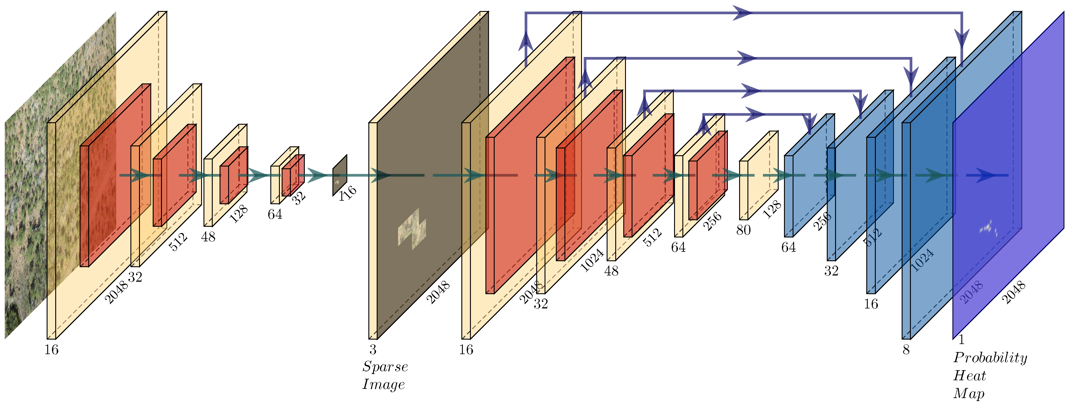
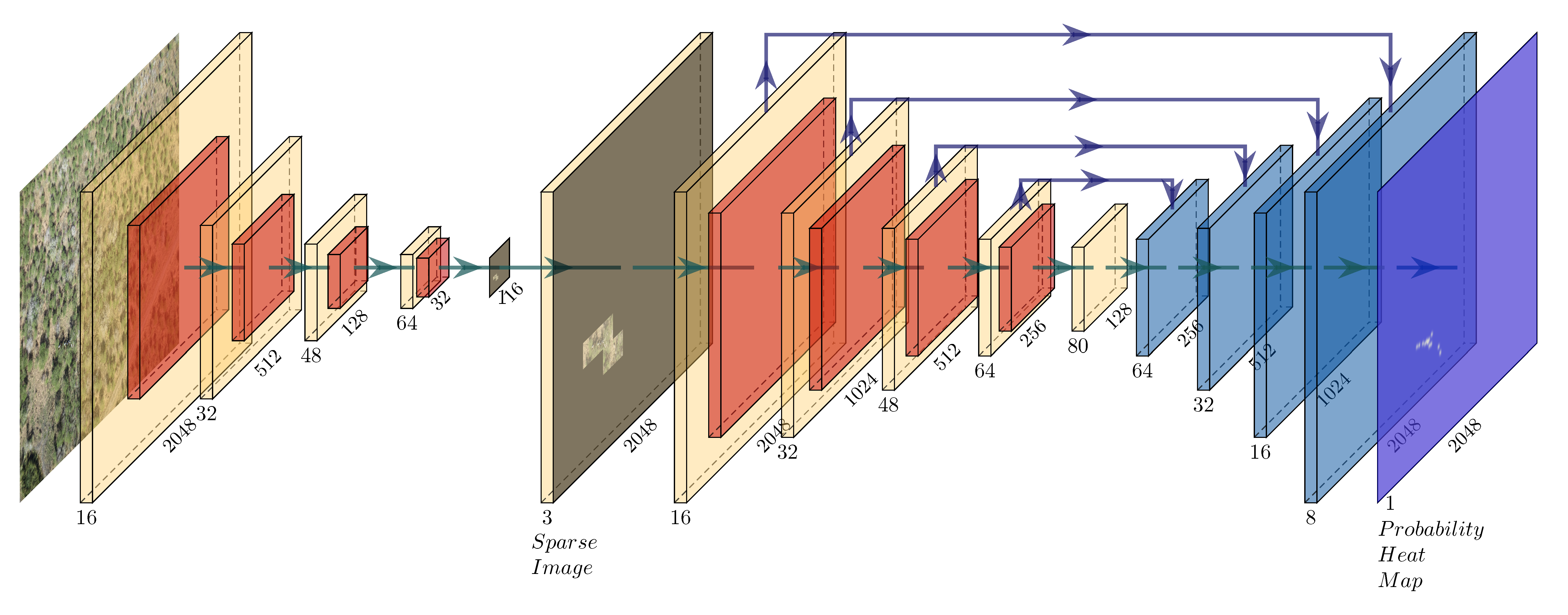
  • We developed a novel end-to-end architecture for counting and localizing small and sparse objects in high-resolution aerial images. This architecture can allow for a real-time implementation on board the UAV, while maintaining comparable accuracy to state-of-the-art techniques.
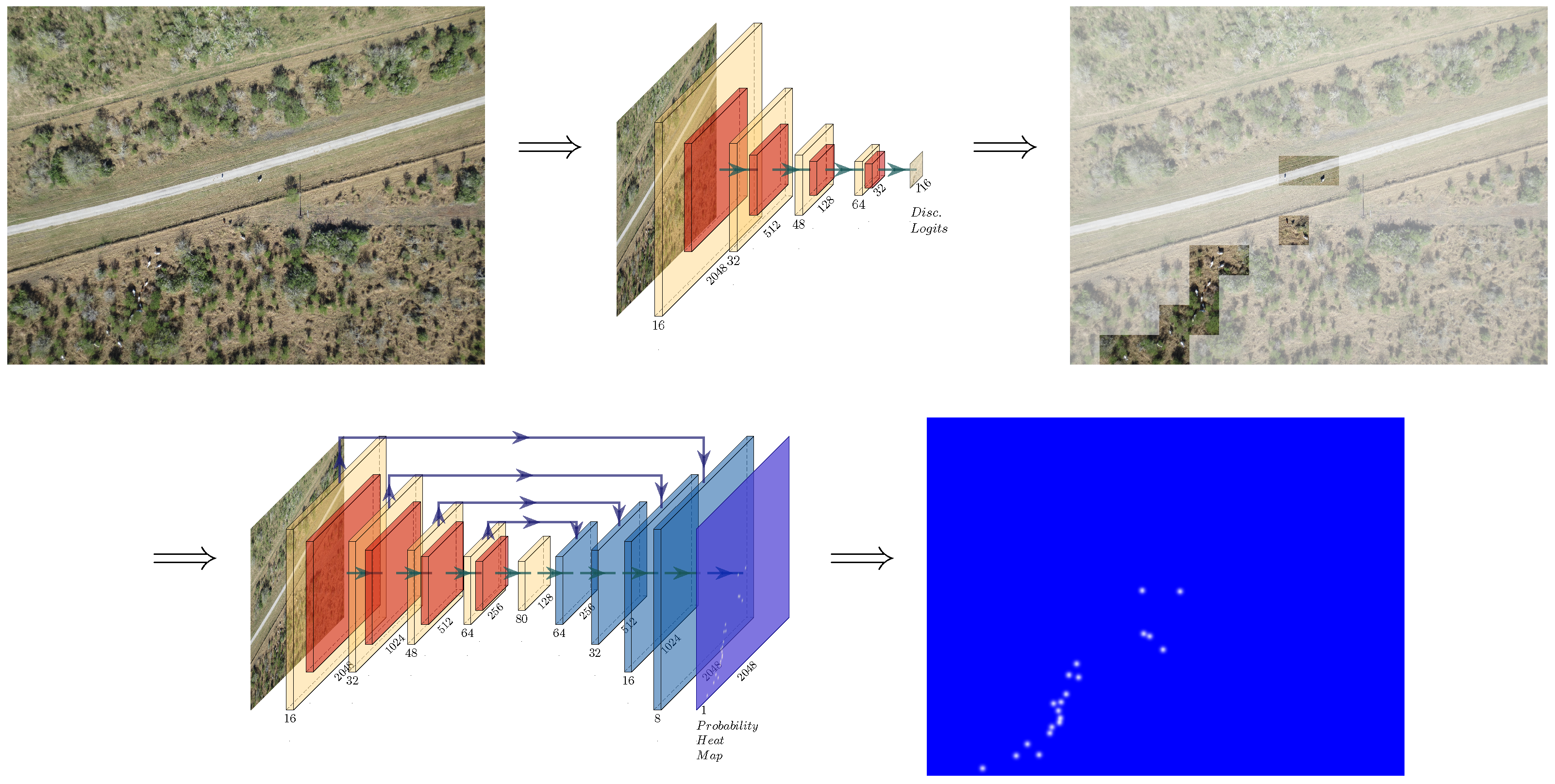
  • Our DisCount network discards a large amount of background information, limiting expensive calculations to important foreground areas.
  • The hard example training part of our algorithm addresses the issues of shadow and occluded animals.
  • We collected a novel UAV dataset, prepared the ground truth for it, and conducted a comprehensive evaluation.

2. Related Work

2.1. Counting Methods

Counting can be divided into several categories based on the annotation methods used for generating the ground-truth data.

2.1.1. Counting Via Detection

One can consider that perfect detection will lead to the perfect counting. In case that objects are distinct and can be easily detected, this assumption is true. In this method, objects need to be annotated by a bounding box. Several methods [5,17,18,19] have applied detection for counting objects. For instance, Ref. [5] have manually annotated bounding box and trained a Faster R-CNN [20] for counting people in a crowd. However, in many cases these methods suffer from heavy occlusions among objects. Moreover, the annotation cost can be very expensive and impractical in very dense objects. In our case, although animals are sparsely located in the image, they are herding together which results in dense patches. Using this theory, we use coarse detection methods to model the first function of density.

2.1.2. Counting Via Density Map

In this case, annotation involves marking a point location for each object in the image. This annotation is based on density heat map and is preferred in scenarios that there are many objects occluding each other. Density heat-map annotation has been used in several cases including counting cells, vehicles, and crowd [6,21,22,23,24,25,26]. Since our counting involves counting occluded objects in the selected patches, we use density heat-map annotation technique.

2.1.3. Counting on Image Level

This counting is based on image level label regression [8,9,27] which is the least expensive annotation technique. However, these methods can only count. Since we are interested in both counting and localization of objects, we did not use image level annotation which is basically the global count in the image.

2.2. Counting Applications

Counting methods have been mainly applied for counting crowd [5,28,29,30,31], vehicles [6,32], and cell [7]. In agriculture, there have been limited research for counting apples and oranges [33], tomatoes [8,9], maize tassels [34], and animals [27]. However, authors are not aware of any fully automatic techniques for counting animals or fruit from aerial imagery. The existing techniques for counting and detection of animals on UAVs [35,36,37] need manual preparation of training data in a way that each image contains a single animal [35,36] or extra sensor such as thermal camera [37]. Due to payload limitation, it is not always possible to add extra sensor; thermal cameras are usually more expensive than optical one which is a prohibitive cost for local farmers. Moreover, counting in [35,36] is performed via a post-processing step by connected component analysis. Our approach is different from previous work as we have developed a fully automatic technique where the region of interest are selected automatically in the first part of the network ( DiscNet) without any manual cropping of imagery and counting is performed automatically in an end-to-end learning procedure on optical imagery.

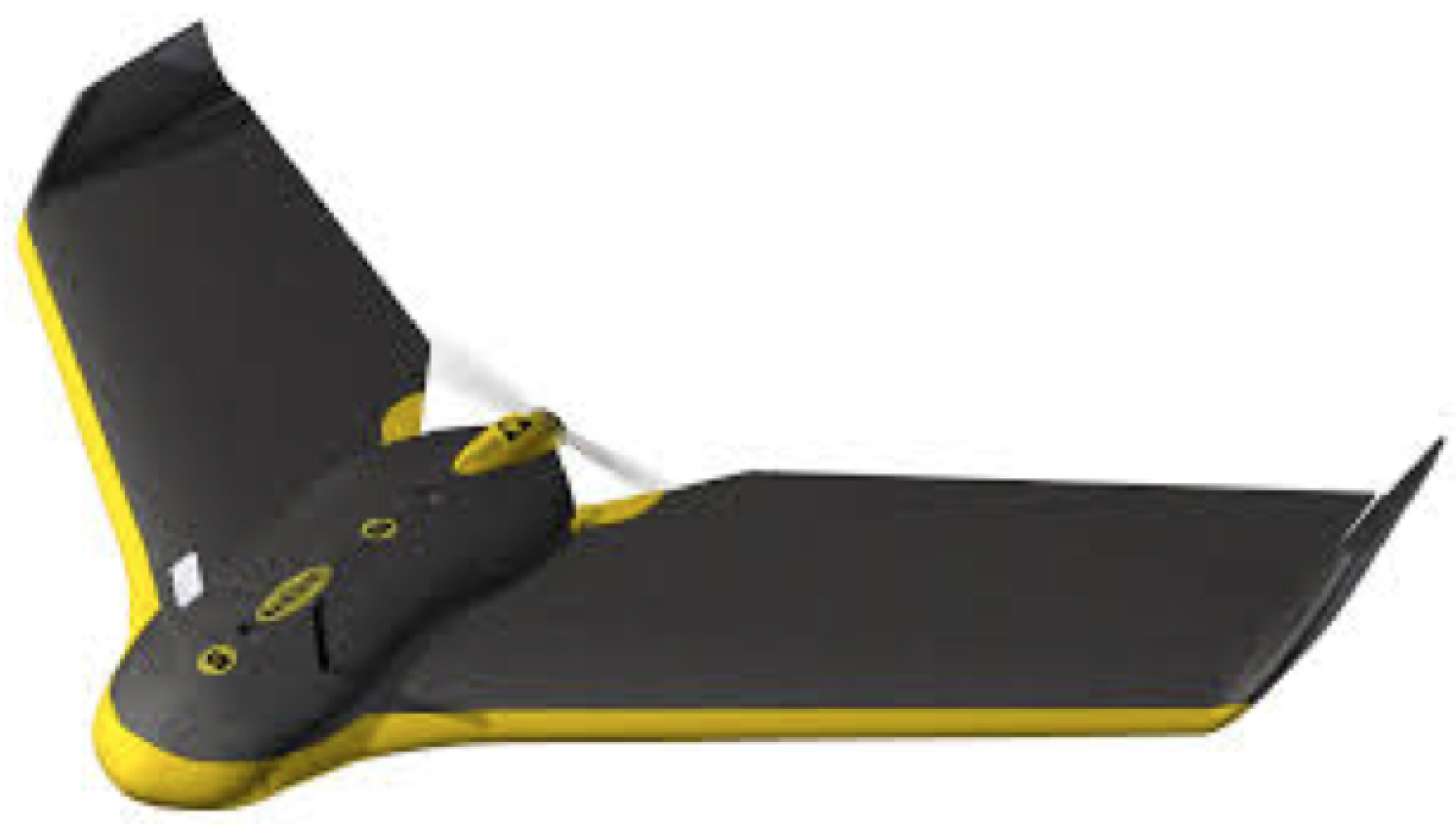
2.3. Unmanned Aerial Systems

In recent years UAS have been extensively used in various areas such as scene understanding and image classification [12], flood detection [16], vehicle tracking [38], forest inventory [39], soil moisture [40], and wildlife and animal management [36,41]. There has been very limited work on use of UAS for monitoring livestock particularly for animal detection, feeding behavior, and health monitoring. For the review of these techniques, see [42].
In addition, several methods based on DNNs [32,43,44,45] have been developed for object detection and tracking in satellite and aerial imagery, particularly vehicles. For counting and detecting of man-made objects ( such as vehicles in parking lots) in aerial imagery, one deal with the imagery that contain an equal distribution of objects of interest and background and there is not any overlap between objects. In typical crowd or vehicle counting from aerial imagery, more than 70% of image contain the object while in our case less than 1 percent of imagery contain the object of interest (cattle). Based on our knowledge there are not any fully automatic techniques for counting sparse objects from UAV imagery. Objects from UAV images are usually flat, proportionally small, and missing normal distinguishing features. Moreover, the ratio of foreground (object of interest) to background data in UAV imagery is prohibitively small. This means that we need to handle sparse information to separate foreground information from background data. Additionally, most domesticated animals used in agriculture are herding. This means that even though they represent a minute amount of sparsely distributed information, they will tend to group, leading to density situations that cannot be accurately handled by detection networks.

3. Data Set

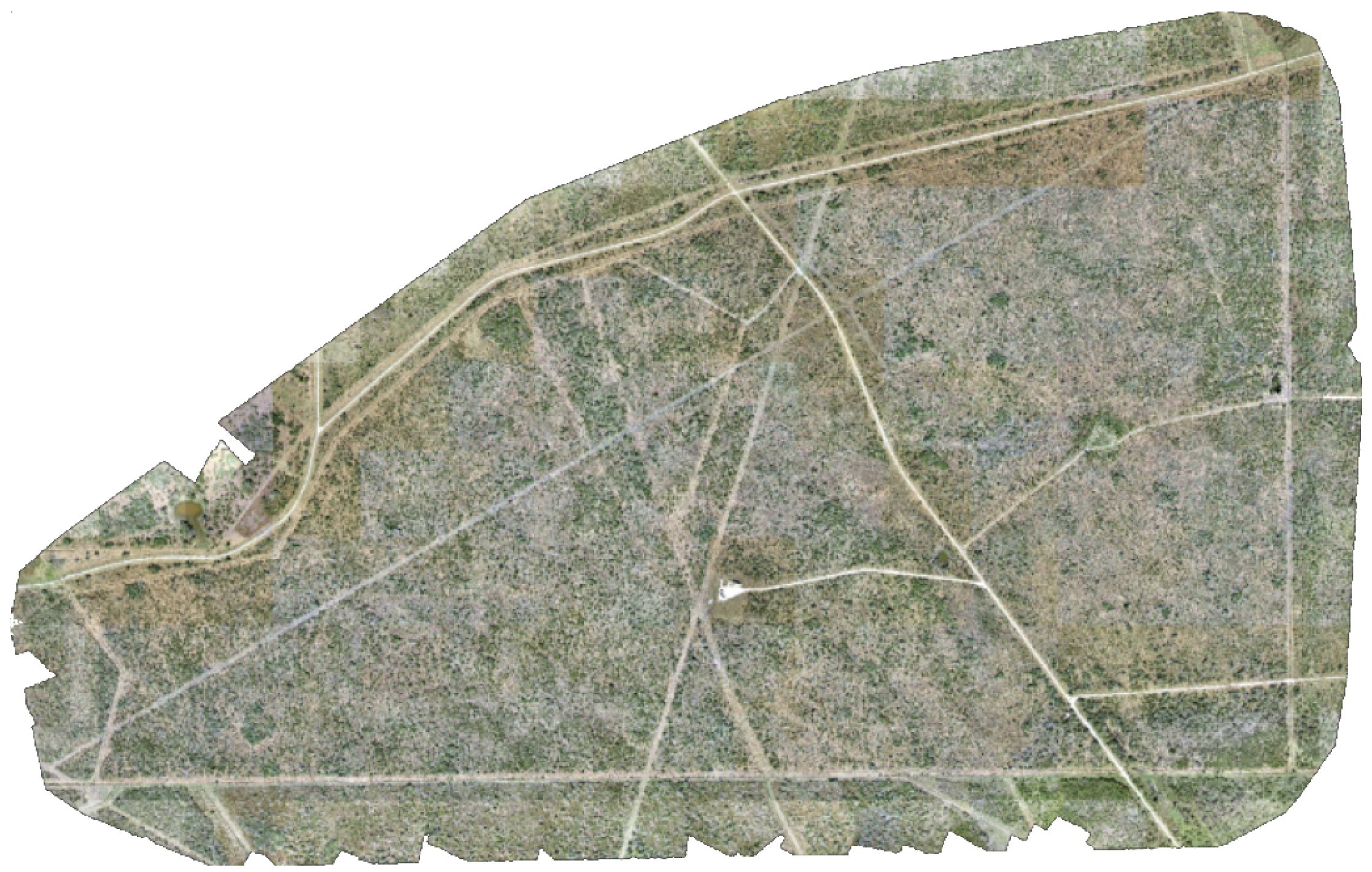
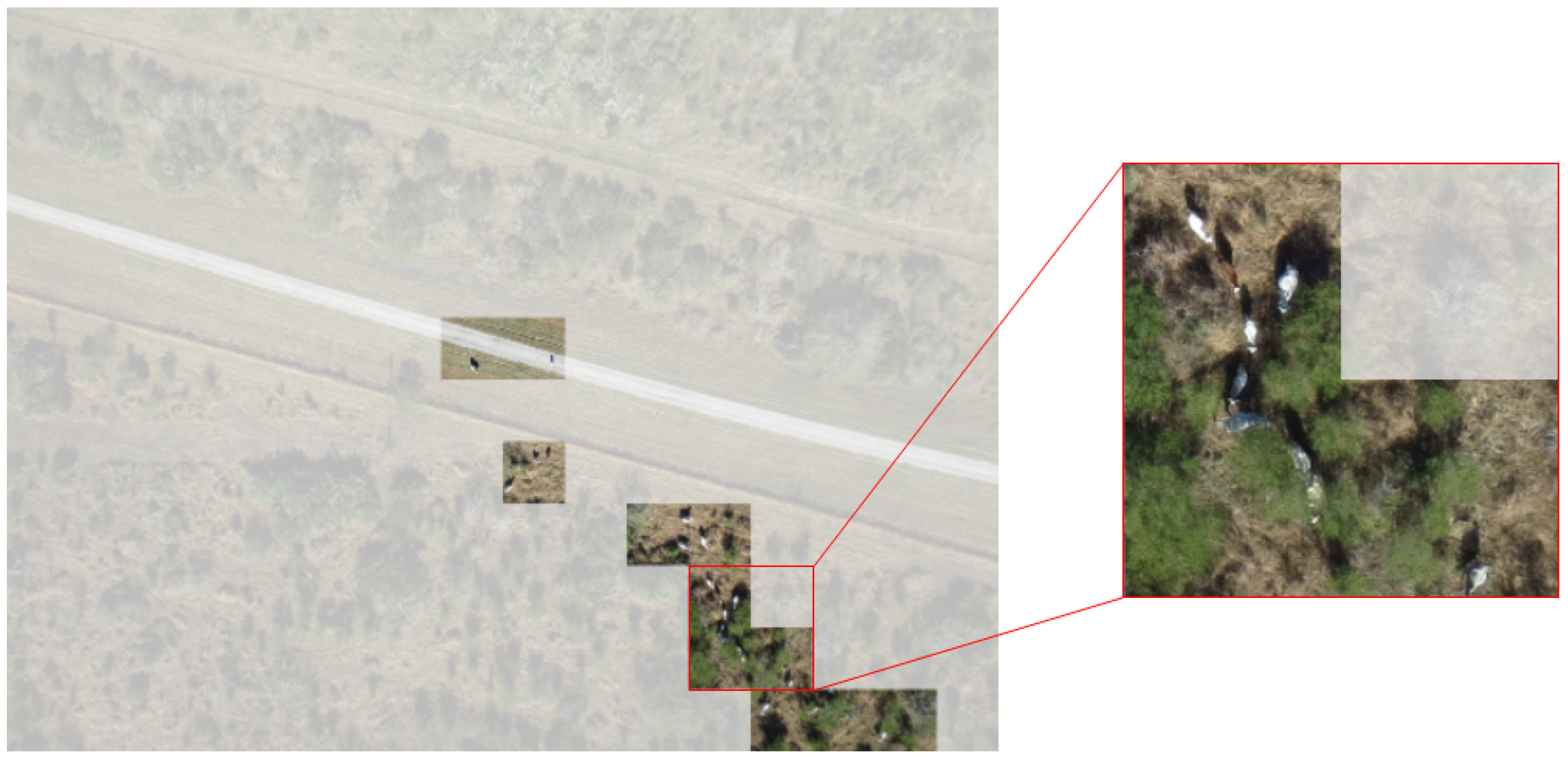
3.1. Data Collection

UAS flights for cattle and wildlife detection were conducted at the Welder Wildlife Foundation in Sinton, TX on December 2015. This coincides with the typical dates for wildlife counts due to leaf drop of deciduous trees. A fixed-wing UAV fitted with a single-channel non-differential GPS and digital RGB camera for photogrammetry was flown by the Measurement Analytics Lab (MANTIS) at Texas A&M University-Corpus Christi under a blanket Certificate of Authorization (COA) approved by the United States Federal Aviation Administration (FAA). Over 600 acres were covered using a fixed-wing small UAV called the SenseFly eBee (Figure 3). It is an ultra-lightweight ( 0 ˜ . 7 kg), fully autonomous platform which has a flight endurance of approximately 50 min on a fully charged battery and light wind, and can withstand wind speeds up to 44 km/h. With this setup, it can cover ten square kilometers per flight mission. For this survey, the platform was equipped with a Canon IXUS 127 HS 16.1 MP RGB camera with automatic exposure adjustment for optimal image exposure. Four flights were conducted at 80 m above ground level with 75% sidelap and 65% endlap to seamlessly cover the entire study area, which consisted of over one thousand individual photographs. The resultant ground sample distance (GSD) was on average 3.8 cm. These images were post-processed using structure-from-motion photogrammetric techniques to generate an orthorectified image mosaic (orthomosaic) (Figure 4).
In this work, Pix4Dmapper Pro (Pix4D SA, 1015 Lausanne, Switzerland) was used to process the imagery. The SfM image processing workflow is summarized as follows [46]: (1) Image sequences are input the software and a keypoint detection algorithm, such as a variant of the scale invariant feature transform (SIFT), is used to automatically extract features and find keypoint correspondences between overlapping images using a keypoint descriptor. SIFT is a well-known algorithm that allows for feature detection regardless of scale, camera rotations, camera perspectives, and changes in illumination [47] (2) Key points as well as approximate values of the image geo-position provided by the UAS autopilot (onboard GPS) are input into a least squares bundle block adjustment to simultaneously solving for camera interior and exterior orientation. Based on this reconstruction, the matching points are verified, and their 3D coordinates calculated to generate a sparse point cloud. (3) To improve reconstruction, ground control points (GCPs) laid out in the survey area are introduced to constrain the solution and optimize reconstruction. GCPs also improve georeferencing accuracy of the generated data products. (4) Densification of the point cloud is then performed using a MultiView Stereo (MVS) algorithm to increase the spatial resolution. The resultant densified set of 3D points is used to generate a triangulated irregular network (TIN) and obtain a digital surface model (DSM). (5) The DSM is then used by the software to project every image pixel and to calculate a geometrically corrected image mosaic (orthomosaic) with uniform scale. Due to the low accuracy of the onboard GPS used to geotag the imagery, ground control targets were laid out in the study area, and RTK differential GPS was used to precisely locate their position within 2 to 4 cm horizontal and vertical accuracy. These control targets were used during the post-processing of the imagery to accurately georeference the orthomosaic image product.

3.2. Dataset Feature Description

The prominent features of this data set are roads, cows, and fences which are standard for ranch land in the southern United States. According to the USDA [48], each head of cattle requires roughly 2 acres (43,560 square feet or 4047 square meters) of ranch land to maintain year-around foraging. On average, a cow when viewed orthogonal occupies roughly 16 square feet, or 1.5 square meters. This means when viewed as an area, a properly populated ranch land will have approximately 0.0037% area that pertain to cattle. As can be seen in Figure 5, any given image in our dataset contains a large amount of background information. In this figure, background information is represented as translucent areas, while important areas, containing objects of interest, are transparent. In addition, cattle are herding animals, meaning they travel in groups. This is especially prevalent in calves, which stay within touching distance of their mothers. Due to this large disparity of area-to-cow and the propensity of the cattle to group up, you end up with unique distributions and sub-distributions of data. The description of these distributions would be densely packed locations of data scattered sparsely in a much larger area. Figure 5 shows an example of sparsity in an image. Out of 192 regions, only 11, signified by transparent areas, represent useful information in the given counting task. Furthermore, out of the useful regions, only 12% of the pixel area represent non-zero values in the probability heat map.

3.3. Dataset Preparation

Individual images taken from the UAV have a native resolution of 3456 by 4608, which is scaled down to 1536 by 2048. Ground-truth annotations for this dataset are center of object point locations, all of which were labeled by hand. The density map is generated by processing the center of point objects with a Gaussian smoothing kernel with a size of 51 and a sigma of 9. This process can be visualized in Figure 6, with an example region, its ground-truth point annotation, and the resultant Gaussian smoothing output. The size of the Gaussian smoothing kernel roughly correlates to the average distance between the tip of a cow’s head and the base of its tail. Due to the scale of the data, some unimportant areas may be labeled as important as they are located proximate to cows. To generate region labels, a sum operation is performed over each region. Any region with a value greater than zero is classified as foreground, with all others classified as background.

4. Our Approach

In this work, we will employ deep-learning models to approximate two density maps, θ d and θ c based on assumptions generated from observation of the data. These assumptions are:
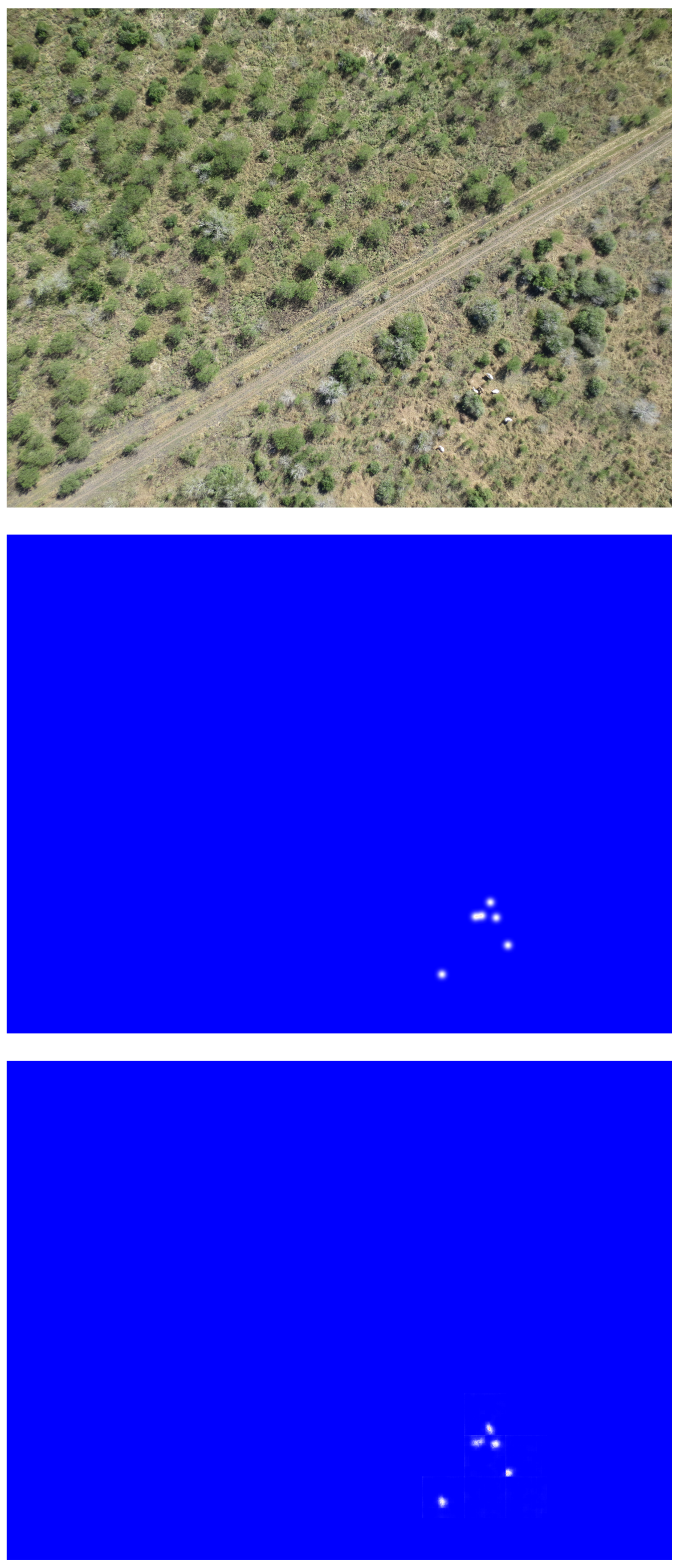
  • The data can be accurately described as a set of two distributions.
  • The majority of our data can be classified as background information.
  • Background information can be safely discarded without losing contextual details.
  • Foreground information can be densely packed.
Therefore, we design a two-stage approach to solve the problem. The first stage, DiscNet, is designed to discriminate between background and foreground data, converting a full feature rich image into a sparse representation where only foreground data and its location is encoded; this will approximate θ d function. The second network, CountNet, approximates θ c by operating on the sparse matrix from DiscNet; CountNet can limit its expensive calculations to regions. The result of this design, DisCountNet, is a two-stage, end-to-end supervised learning process that maintains remarkable accuracy while yielding a real-time solution to the provided problem.

4.1. Implementation and Training

The design for DisCountNet is detailed in Figure 2, and shows the full end-to-end implementation. DiscNet (the first stage) is an encoder characterized by convolutions of large kernels and leaky RELU activation functions followed by aggressive pooling. The first four convolutions use kernels with sizes of seven, six, five, and four. The first three pooling operations are all max pooling with a kernel and stride of four, and the final pooling operation is another max pooling layer with stride and kernel size of two. The last next to last layer in the network is a final one-by-one convolution to reduce the feature map depth to two, followed by a SoftMax activation, yielding a 12 by 16 matrix of values that represent the likelihood that a cow is found in a given region. The aggressive striding allows us to use larger kernel sizes to capture contextual information that could be lost while limiting expensive operations. DiscNet then uses this matrix to convert the original input image into a sparse representation, operating on the assumptions listed above. CountNet uses the sparse representation to generate per-pixel probability values. This flow of information can be visualized in Figure 7, which shows different data representations at different stages of the proposed network. Our training procedure is depicted in Algorithm 1. Given the dataset { X i } i = 0 N , DiscNet gets trained using the full images and region label ground truths via a weighted cross entropy loss to determine if there is a cow in a given region. Each data X i consist of R ( i ) regions, where each region is labeled by y r ( i ) with r = 1 where r = 1 R ( i ) . The result of the network prediction is denoted as y ˜ r ( i ) . We use a weighted cross entropy minimization equation, which is given by Equation (1); for convenience, we drop the superscript ( i ) in the formula.
d = r ( y r p r 0.5 log ( y r ˜ ) + ( 1 y r ) p r 0.5 log ( 1 y r ˜ ) ) .
where p r [ 0 , 1 ] and represents the percentage of regions with desired information. This weighted loss function serves to counterweight the loss values for our unbalanced data set. For example, if an image is 90% background regions, the loss for foreground regions will be ten times higher. This will cause the network to weigh the loss for positive examples more highly than negative examples, resulting in an increased number of false positives and fewer false negatives. In our given implementation, a false negative will hurt the performance much more than a false positive. As an example, a false negative in the discriminator would mean that a region with a cow is not passed to CountNet, meaning no cows can be detected. However, a false positive means that a region without a cow is passed on, for which CountNet can still compensate. In the second stage, as CountNet seeks to model a different function based on Assumption 4, it uses a different implementation. CountNet features a U-Net structure [49] with modified operations. Operating on a sparse representation of the original image generated by DiscNet, CountNet creates a sparse density map. The encoding pathway features four convolution-pooling operations with skip connections to the decoding pathway, which uses transposed convolutions. All the pooling operations are max pooling with a kernel and stride of two. Each of the convolutions uses a three-by-three kernel, and all transposed convolutions use a stride of two. Finally, the network uses a one-by-one convolution with one feature depth that represents the likelihood that a cow is in one given pixel. The U-Net-like-architecture is proven for providing accurate inferences while maintaining contextual information for per-pixel tasks.
CountNet is trained by the sparse data generated by DiscNet. CountNet’s loss value is generated using regions and corresponding ground-truth density map regions by minimizing the Mean Square Error. The 2 loss function, is given by Equation (2) where z i is a given ground-truth density map and z i ˜ is a prediction,
c = 1 2 N i | | z i ˜ z i | | 2 2 .
Algorithm 1: DisCount training algorithm is illustrated here.
Remotesensing 11 01128 i001

4.2. Hard Example Training

During end-to-end training, CountNet maintains a list of loss values per region. At the end of each epoch, it sorts this list, then truncates the lowest half. CountNet then randomly perturbs these regions using random flipping and rotating, training again with a larger batch size. The loss from this training is again stored, and the process is repeated m 1 times. As the population decreases by half in every iteration, m should be chosen to ensure that the population of regions does not drop below a given batch size. On observation, regions used multiple times contain argumentative features, such as black cows that look similar to shadows or obscured cows behind foliage.

5. Evaluation Metrics

For evaluation, we used five metrics in addition to comparing parameters between DisCountNet, RetinaNet [14] and CSRNet [50]. The targeted goal is to have as-accurate-as-possible counting and density map generation while providing a real-time solution on portable hardware. The metrics can be broken into three different sections; image level label comparison, region level label comparison, and generated density map quality comparison.

5.1. Image Level Label Metrics

To compare raw counting results, we use mean squared error (mSE) and mean absolute error (mAE). The resultant values provide us with an idea of the average error expected for any image in our testing set. In both equations, n is the total number of images, y t is a given ground-truth label count, and y ˜ t is our count prediction for image t.
m S E = 1 n t = 1 n ( y t y ˜ t ) 2 m A E = 1 n t = 1 n | y t y ˜ t |

5.2. Image Region Level Metric

The grid average mean absolute error (GAME) [6] metric provides more accurate information for counting quality. Mean absolute error as a metric does not care where errors occur as long as they average out, where GAME simultaneously considers the object count, and the location estimated for the objects. The formula for GAME is as follows:
G A M E ( L ) = 1 n t = 1 n ( r = 1 4 L | y t r y ˜ t r | )
where n is the total number of images, L is the amount of gridlines in each dimension, and y t r is the actual count for image t on region r. It should be noted that GAME(0) is equal to the mAE, as the region considered is the whole image.

5.3. Density Map Quality Comparison

To evaluate the quality of the produced density heat maps, we use peak signal-to-noise ratio (PSNR) and structural similarity (SSIM) [51]. These metrics provide insight to the quality of the generated density map compared to the ground truth. Standard implementations of these metrics are non-distance evaluations, meaning that they cannot be used to evaluate raw counting results, but rather to provide an insight into a network’s ability to create accurate per-pixel values. The formula for PSNR can be found below, with M A X i being the maximum possible pixel value of a given image and mSE being the mean squared error found in Equation (3).
P S N R = 10 · log 10 MAX I 2 mSE
The formula for structural similarity is as follows:
S S I M ( x , y ) = ( 2 μ x μ y + c 1 ) ( 2 σ x y + c 2 ) ( μ x 2 + μ y 2 + c 1 ) ( σ x 2 + σ y 2 + c 2 )
where μ represents the mean, σ represents the standard deviation, σ x y is covariance, x is a ground truth, and y is a prediction. Finally, c 1 and c 2 are variables to stabilize division.

6. Results

6.1. Experimental Setup

We have compared the performance of our technique with two state-of-the-art techniques namely RetinaNet and CSRNet [14,50]. RetinaNet is a detection network [14] that generates bounding boxes and CSRNet generates a density map [50].
All networks were trained on a Spectrum TXR410-0032R Deep Learning Dev Box, leveraging an Intel Core 17-5930K, 64 GB of RAM, and four Nvidia GeForce Titan Xs.
DisCountNet was trained with the Adam [52] optimizer with a learning rate of 1e-3. The batch size for DiscNet was 1, and the batch size for CountNet is the number of regions detected by DiscNet. During hard example training, the batch size of DiscNet was set to be 24, and m was chosen to be three. The number of repetitions of hard example training, m, was set to three to maintain a large sample population. A larger dataset could theoretically use a larger number of repetitions, as the batch size of regions could remain higher.
To generate positive anchors, RetinaNet was trained using images that contained cows extracted from a three-by-three grid of the original images using bounding box ground truths.
Validation was run with a Dell Inspiron 15-7577 using a solid-state drive, i5-7300 processor, 16 GB of RAM, and an Nvidia 1060 Max-Q. To operate on more limited hardware, images were split into non-overlapping regions before being processed by CSRNet and RetinaNet. For RetinaNet [14], a three-by-three grid was used to generate the regions, while CSRNet [50] was validated using a two-by-two grid. Using this hardware as an analog for consumer attainable and portable hardware, DisCountNet averaged 34 frames per second. To compare, RetinaNet [14] averaged 4 frames per second, and CSRNet [50] averaged 12 frames per second. This shows that only our technique can count and localize objects in real time.

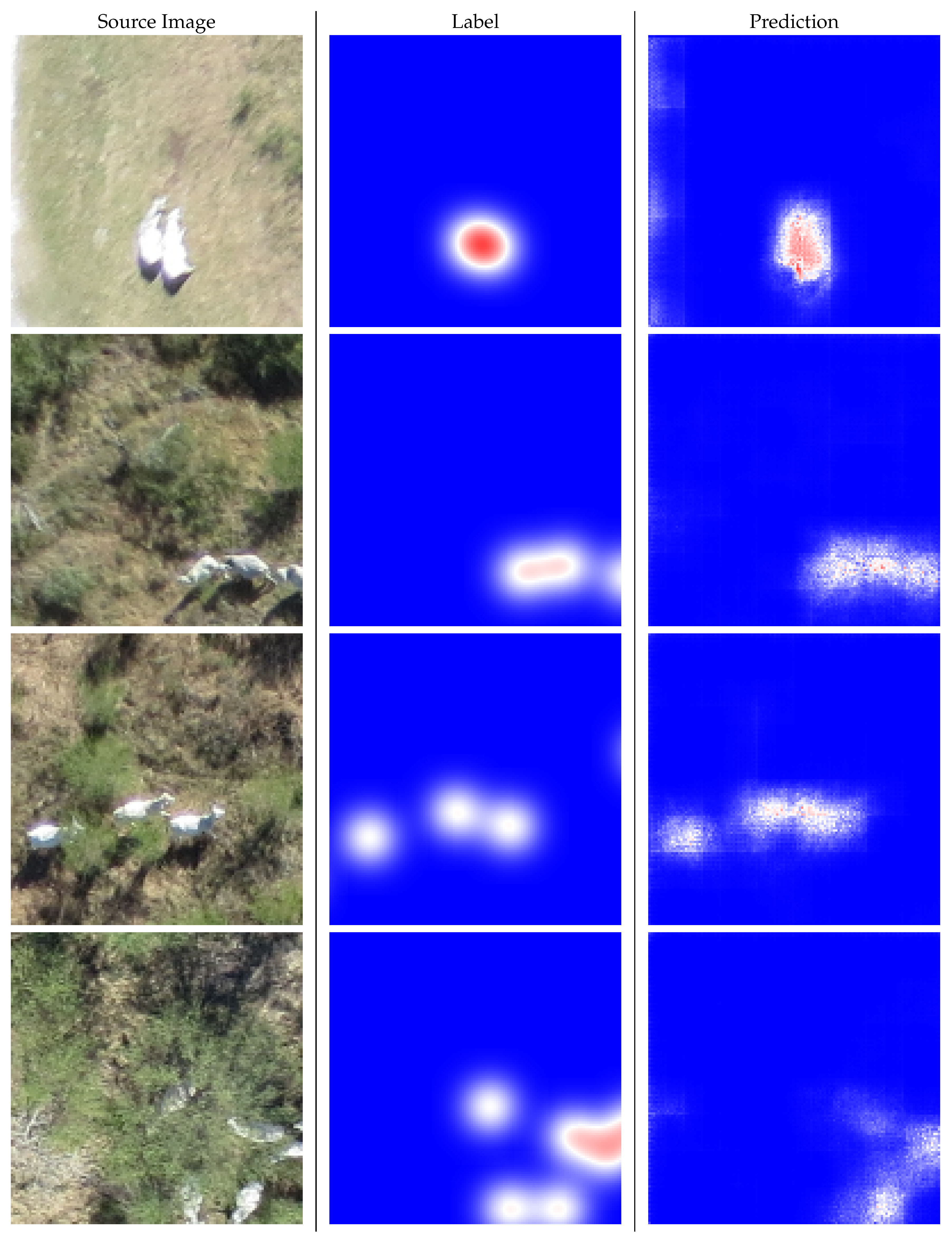
6.2. Qualitative and Quantitative Results

A sample full image, its ground truth, and the predicted density map by our algorithm are shown in Figure 8. In addition to the density map, the network predicts 6 objects in this image, which corresponds to the actual count. As it can be seen in Figure 8, our method is able to detect small and sparse objects in large UAV images. Further results for selected regions by our discriminator network are shown in Figure 9. This figure shows that our method can distinguish between two adjacent cattle and those animals that our occluded by foliage.
As can be seen in Table 1, DisCountNet maintains competitive metrics despite using just over 1% of the parameters of current state-of-the-art networks. In addition, DisCountNet would have the benefit of limiting computation whereas other networks would not. For example, in an empty image, DisCountNet would only use the operations of DiscNet, as CountNet would not run. RetinaNet [14] and CSRNet [50] however, would need to use their full operations on the empty image, resulting in computations with no benefit.
As it can be seen in Table 2 and Table 3, DisCountNet outperformed state-of-the-art in all GAME metrics as well as SSIM. This shows that our method is more accurate in simultaneous counting and localization of objects compared to others.
SSIM (Table 3) metric is 1e-4 from being a perfect score for DisCountNet. This is due to the fact that when using a sparse representation, we allow for perfect zero output. This results in absolutely no error for the majority (around 80%) of all pixels. CSRNet [50] does not have this type of design, so every pixel output value can be extremely close to zero, but statistically will not be zero. This results in a small error value in every pixel which is even more pronounced when comparing SSIM over other metrics.

7. Conclusions

In this paper, we propose an innovative method to work with sparse datasets by designing a fully convolutional counting and localization method. Our method outperformed state-of-the-art techniques in quantitative metrics while providing real-time results. Through innovative design, we limit operations to only important areas while discarding non-important areas. While our method greatly improves the counting and localization performance, it has the limitation of detecting and counting highly occluded objects. As it can be seen on the bottom row of Figure 3, our network has difficulty detecting cows inside shrubbery with high occlusion. This technique is easily portable to other application domains, as it provides general implementations rather than specific hand-crafted techniques. Our technique can possibly be expanded to an iterative series of DiscNets, or a cascade of weak convolutional regional classifiers. By the iterative process of dense to sparse information representations, successive networks would work on less and less information.

Author Contributions

Conceptualization, M.R. and D.D.; methodology, M.R., D.D. and M.Y.; software, D.D.; validation, M.R., D.D. and M.Y.; formal analysis, M.R., D.D. and M.Y.; investigation, M.R., D.D. and M.Y.; resources, M.R. and M.J.S.; data curation, D.D.; writing—original draft preparation, M.R. and D.D.; writing—review and editing, M.R., D.D., M.Y. and M.J.S.; supervision, M.R.; project administration, M.R.; funding acquisition, M.R.

Funding

This research is supported by Amazon and Texas Comprehensive Research Fund.

Conflicts of Interest

The authors declare no conflict of interest.

References

  1. Chan, A.B.; Liang, Z.S.J.; Vasconcelos, N. Privacy preserving crowd monitoring: Counting people without people models or tracking. In Proceedings of the 2008 IEEE Conference on Computer Vision and Pattern Recognition, Anchorage, AK, USA, 23–28 June 2008; pp. 1–7. [Google Scholar]
  2. Idrees, H.; Saleemi, I.; Seibert, C.; Shah, M. Multi-source multi-scale counting in extremely dense crowd images. In Proceedings of the IEEE Conference on Computer Vision and Pattern Recognition, Portland, OR, USA, 23–28 June 2013; pp. 2547–2554. [Google Scholar]
  3. Shen, Z.; Xu, Y.; Ni, B.; Wang, M.; Hu, J.; Yang, X. Crowd counting via adversarial cross-scale consistency pursuit. In Proceedings of the IEEE Conference on Computer Vision and Pattern Recognition, Salt Lake City, UT, USA, 18–22 June 2018; pp. 5245–5254. [Google Scholar]
  4. Boominathan, L.; Kruthiventi, S.S.; Babu, R.V. Crowdnet: A deep convolutional network for dense crowd counting. In Proceedings of the 24th ACM international conference on Multimedia, Amsterdam, The Netherlands, 15–19 October 2016; pp. 640–644. [Google Scholar]
  5. Liu, J.; Gao, C.; Meng, D.; Hauptmann, A.G. Decidenet: Counting varying density crowds through attention guided detection and density estimation. In Proceedings of the IEEE Conference on Computer Vision and Pattern Recognition, Salt Lake City, UT, USA, 18–22 June 2018; pp. 5197–5206. [Google Scholar]
  6. Guerrero-Gómez-Olmedo, R.; Torre-Jiménez, B.; López-Sastre, R.; Maldonado-Bascón, S.; Onoro-Rubio, D. Extremely overlapping vehicle counting. In Pattern Recognition and Image Analysis; Springer: Cham, Switzerland, 2015; pp. 423–431. [Google Scholar]
  7. Xie, W.; Noble, J.A.; Zisserman, A. Microscopy cell counting and detection with fully convolutional regression networks. Comput. Methods Biomech. Biomed. Eng. Imaging Vis. 2018, 6, 283–292. [Google Scholar] [CrossRef]
  8. Rahnemoonfar, M.; Sheppard, C. Deep count: Fruit counting based on deep simulated learning. Sensors 2017, 17, 905. [Google Scholar] [CrossRef] [PubMed]
  9. Rahnemoonfar, M.; Sheppard, C. Real-time yield estimation based on deep learning. Proc. SPIE 2017, 10218. [Google Scholar] [CrossRef]
  10. Huang, L.C.; Kulkarni, K.; Jha, A.; Lohit, S.; Jayasuriya, S.; Turaga, P. CS-VQA: Visual Question Answering with Compressively Sensed Images. In Proceedings of the 2018 25th IEEE International Conference on Image Processing (ICIP), Athens, Greece, 7–10 October 2018; pp. 1283–1287. [Google Scholar]
  11. Fukui, A.; Park, D.H.; Yang, D.; Rohrbach, A.; Darrell, T.; Rohrbach, M. Multimodal compact bilinear pooling for visual question answering and visual grounding. arXiv 2016, arXiv:1606.01847. [Google Scholar]
  12. Sheppard, C.; Rahnemoonfar, M. Real-time scene understanding for UAV imagery based on deep convolutional neural networks. In Proceedings of the 2017 IEEE International Geoscience and Remote Sensing Symposium (IGARSS), Fort Worth, TX, USA, 23–28 July 2017; pp. 2243–2246. [Google Scholar]
  13. Redmon, J.; Farhadi, A. YOLO9000: Better, faster, stronger. In Proceedings of the IEEE Conference on Computer Vision and Pattern Recognition, Honolulu, HI, USA, 21–26 July 2017; pp. 7263–7271. [Google Scholar]
  14. Lin, T.Y.; Goyal, P.; Girshick, R.; He, K.; Dollár, P. Focal loss for dense object detection. In Proceedings of the IEEE International Conference on Computer Vision (ICCV), Venice, Italy, 22–29 October 2017; pp. 2980–2988. [Google Scholar]
  15. Kamangir, H.; Rahnemoonfar, M.; Dobbs, D.; Paden, J.; Fox, G.C. Detecting ice layers in Radar images with deep hybrid networks. In Proceedings of the IEEE Conference on Geoscience and Remote Sensing (IGARSS), Valencia, Spain, 22–27 July 2018. [Google Scholar]
  16. Rahnemoonfar, M.; Robin, M.; Miguel, M.V.; Dobbs, D.; Adams, A. Flooded area detection from UAV images based on densely connected recurrent neural networks. In Proceedings of the 2017 IEEE International Geoscience and Remote Sensing Symposium (IGARSS), Fort Worth, TX, USA, 23–28 July 2017; pp. 3743–3746. [Google Scholar]
  17. Chattopadhyay, P.; Vedantam, R.; Selvaraju, R.R.; Batra, D.; Parikh, D. Counting everyday objects in everyday scenes. In Proceedings of the IEEE Conference on Computer Vision and Pattern Recognition, Honolulu, HI, USA, 21–26 July 2017; pp. 1135–1144. [Google Scholar]
  18. Zhang, C.; Li, H.; Wang, X.; Yang, X. Cross-scene crowd counting via deep convolutional neural networks. In Proceedings of the IEEE Conference on Computer Vision and Pattern Recognition, Boston, MA, USA, 7–12 June 2015; pp. 833–841. [Google Scholar]
  19. Hu, P.; Ramanan, D. Finding tiny faces. In Proceedings of the IEEE Conference on Computer Vision and Pattern Recognition, Honolulu, HI, USA, 21–26 July 2017; pp. 951–959. [Google Scholar]
  20. Ren, S.; He, K.; Girshick, R.; Sun, J. Faster R-CNN: Towards Real-Time Object Detection with Region Proposal Networks. In Advances in Neural Information Processing Systems 28; Cortes, C., Lawrence, N.D., Lee, D.D., Sugiyama, M., Garnett, R., Eds.; Curran Associates, Inc.: Red Hook, NY, USA, 2015; pp. 91–99. [Google Scholar]
  21. Zhang, Y.; Zhou, D.; Chen, S.; Gao, S.; Ma, Y. Single-image crowd counting via multi-column convolutional neural network. In Proceedings of the IEEE Conference on Computer Vision and Pattern Recognition, Las Vegas, NV, USA, 26 June–1 July 2016; pp. 589–597. [Google Scholar]
  22. Fiaschi, L.; Köthe, U.; Nair, R.; Hamprecht, F.A. Learning to count with regression forest and structured labels. In Proceedings of the 21st International Conference on Pattern Recognition (ICPR2012), Tsukuba, Japan, 11–15 November 2012; pp. 2685–2688. [Google Scholar]
  23. Sam, D.B.; Surya, S.; Babu, R.V. Switching convolutional neural network for crowd counting. In Proceedings of the 2017 IEEE Conference on Computer Vision and Pattern Recognition (CVPR), Honolulu, HI, USA, 21–26 July 2017; pp. 4031–4039. [Google Scholar]
  24. Idrees, H.; Tayyab, M.; Athrey, K.; Zhang, D.; Al-Maadeed, S.; Rajpoot, N.; Shah, M. Composition loss for counting, density map estimation and localization in dense crowds. In Proceedings of the European Conference on Computer Vision (ECCV), Munich, Germany, 8–14 September 2018; pp. 532–546. [Google Scholar]
  25. Walach, E.; Wolf, L. Learning to count with cnn boosting. In Computer Vision—ECCV 2016; Springer: Cham, Switzerland, 2016; pp. 660–676. [Google Scholar]
  26. Deb, D.; Ventura, J. An aggregated multicolumn dilated convolution network for perspective-free counting. In Proceedings of the IEEE Conference on Computer Vision and Pattern Recognition Workshops, Salt Lake City, UT, USA, 18–22 June 2018; pp. 195–204. [Google Scholar]
  27. Wawerla, J.; Marshall, S.; Mori, G.; Rothley, K.; Sabzmeydani, P. Bearcam: Automated wildlife monitoring at the arctic circle. Mach. Vis. Appl. 2009, 20, 303–317. [Google Scholar] [CrossRef]
  28. Shang, C.; Ai, H.; Bai, B. End-to-end crowd counting via joint learning local and global count. In Proceedings of the 2016 IEEE International Conference on Image Processing (ICIP), Phoenix, AZ, USA, 25–28 September 2016; pp. 1215–1219. [Google Scholar]
  29. Liu, X.; van de Weijer, J.; Bagdanov, A.D. Leveraging unlabeled data for crowd counting by learning to rank. In Proceedings of the IEEE Conference on Computer Vision and Pattern Recognition, Salt Lake City, UT, USA, 18–22 June 2018; pp. 7661–7669. [Google Scholar]
  30. Babu Sam, D.; Sajjan, N.N.; Venkatesh Babu, R.; Srinivasan, M. Divide and grow: Capturing huge diversity in crowd images with incrementally growing CNN. In Proceedings of the IEEE Conference on Computer Vision and Pattern Recognition, Salt Lake City, UT, USA, 18–22 June 2018; pp. 3618–3626. [Google Scholar]
  31. Shi, Z.; Zhang, L.; Liu, Y.; Cao, X.; Ye, Y.; Cheng, M.M.; Zheng, G. Crowd counting with deep negative correlation learning. In Proceedings of the IEEE Conference on Computer Vision and Pattern Recognition, Salt Lake City, UT, USA, 18–22 June 2018; pp. 5382–5390. [Google Scholar]
  32. Tayara, H.; Soo, K.G.; Chong, K.T. Vehicle detection and counting in high-resolution aerial images using convolutional regression neural network. IEEE Access 2018, 6, 2220–2230. [Google Scholar] [CrossRef]
  33. Chen, S.W.; Shivakumar, S.S.; Dcunha, S.; Das, J.; Okon, E.; Qu, C.; Taylor, C.J.; Kumar, V. Counting apples and oranges with deep learning: A data-driven approach. IEEE Robot. Autom. Lett. 2017, 2, 781–788. [Google Scholar] [CrossRef]
  34. Lu, H.; Cao, Z.; Xiao, Y.; Zhuang, B.; Shen, C. TasselNet: Counting maize tassels in the wild via local counts regression network. Plant Methods 2017, 13, 79. [Google Scholar] [CrossRef] [PubMed]
  35. Chamoso, P.; Raveane, W.; Parra, V.; González, A. UAVs applied to the counting and monitoring of animals. In Ambient Intelligence-Software and Applications; Springer: Cham, Switzerland, 2014; pp. 71–80. [Google Scholar]
  36. Rivas, A.; Chamoso, P.; González-Briones, A.; Corchado, J. Detection of Cattle Using Drones and Convolutional Neural Networks. Sensors 2018, 18, 2048. [Google Scholar] [CrossRef] [PubMed]
  37. Longmore, S.; Collins, R.; Pfeifer, S.; Fox, S.; Mulero-Pázmány, M.; Bezombes, F.; Goodwin, A.; De Juan Ovelar, M.; Knapen, J.; Wich, S. Adapting astronomical source detection software to help detect animals in thermal images obtained by unmanned aerial systems. Int. J. Remote Sens. 2017, 38, 2623–2638. [Google Scholar] [CrossRef]
  38. Koskowich, B.J.; Rahnemoonfar, M.; Starek, M. Virtualot—A Framework Enabling Real-Time Coordinate Transformation & Occlusion Sensitive Tracking Using UAS Products, Deep Learning Object Detection & Traditional Object Tracking Techniques. In Proceedings of the IEEE International Geoscience and Remote Sensing Symposium(IGARSS), Valencia, Spain, 22–27 July 2018; pp. 6416–6419. [Google Scholar]
  39. Wallace, L.; Lucieer, A.; Watson, C.; Turner, D. Development of a UAV-LiDAR system with application to forest inventory. Remote Sens. 2012, 4, 1519–1543. [Google Scholar] [CrossRef]
  40. D’Oleire Oltmanns, S.; Marzolff, I.; Peter, K.; Ries, J. Unmanned aerial vehicle (UAV) for monitoring soil erosion in Morocco. Remote Sens. 2012, 4, 3390–3416. [Google Scholar] [CrossRef]
  41. Chabot, D.; Bird, D.M. Wildlife research and management methods in the 21st century: Where do unmanned aircraft fit in? J. Unmanned Veh. Syst. 2015, 3, 137–155. [Google Scholar] [CrossRef]
  42. Barbedo, J.G.A.; Koenigkan, L.V. Perspectives on the use of unmanned aerial systems to monitor cattle. Outlook Agric. 2018, 47, 214–222. [Google Scholar] [CrossRef]
  43. Jin, X.; Davis, C.H. Vehicle detection from high-resolution satellite imagery using morphological shared-weight neural networks. Image Vis. Comput. 2007, 25, 1422–1431. [Google Scholar] [CrossRef]
  44. Jiang, Q.; Cao, L.; Cheng, M.; Wang, C.; Li, J. Deep neural networks-based vehicle detection in satellite images. In Proceedings of the 2015 International Symposium on Bioelectronics and Bioinformatics (ISBB), Beijing, China, 14–17 October 2015; pp. 184–187. [Google Scholar]
  45. Miyamoto, H.; Uehara, K.; Murakawa, M.; Sakanashi, H.; Nasato, H.; Kouyama, T.; Nakamura, R. Object Detection in Satellite Imagery Using 2-Step Convolutional Neural Networks. In Proceedings of the IEEE International Geoscience and Remote Sensing Symposium(IGARSS), Valencia, Spain, 22–27 July 2018; pp. 1268–1271. [Google Scholar]
  46. Starek, M.J.; Davis, T.; Prouty, D.; Berryhill, J. Small-scale UAS for geoinformatics applications on an island campus. In Proceedings of the 2014 Ubiquitous Positioning Indoor Navigation and Location Based Service (UPINLBS), Corpus Christi, TX, USA, 20–21 November 2014; pp. 120–127. [Google Scholar]
  47. Lowe, D.G. Distinctive image features from scale-invariant keypoints. Int. J. Comput. Vis. 2004, 60, 91–110. [Google Scholar] [CrossRef]
  48. United States Department of Agriculture. Balancing Animals with Your Forage; United States Department of Agriculture: Washington, DC, USA, 2009.
  49. Ronneberger, O.; Fischer, P.; Brox, T. U-net: Convolutional networks for biomedical image segmentation. In Medical Image Computing and Computer-Assisted Intervention—MICCAI 2015; Springer: Cham, Switzerland, 2015; pp. 234–241. [Google Scholar]
  50. Li, Y.; Zhang, X.; Chen, D. Csrnet: Dilated convolutional neural networks for understanding the highly congested scenes. In Proceedings of the IEEE conference on computer vision and pattern recognition, Salt Lake City, UT, USA, 18–22 June 2018; pp. 1091–1100. [Google Scholar]
  51. Wang, Z.; Simoncelli, E.P.; Bovik, A.C. Multiscale structural similarity for image quality assessment. In Proceedings of the Thrity-Seventh Asilomar Conference on Signals, Systems & Computers, Pacific Grove, CA, USA, 9–12 November 2003; Volume 2, pp. 1398–1402. [Google Scholar]
  52. Kingma, D.P.; Ba, J. Adam: A method for stochastic optimization. arXiv 2014, arXiv:1412.6980. [Google Scholar]
Figure 1. The difference between front-view of an object in typical ground-based human-centric photograph (Top Left) and top view in aerial images (Right; Bottom Left); Objects in aerial images are small, flat, and sparse; moreover, objects and backgrounds are highly imbalanced. In human-centric photographs, different parts of objects (head, tail, body, legs) are clearly observable while aerial imagery present very coarse features. In addition, aerial imagery presents argumentative features, such as shadows.
Remotesensing 11 01128 g001
Figure 2. Our DisCount network: An end-to-end learning framework for counting sparse objects in high-resolution images. It includes two networks: The first network (DiscNet) will select regions and the second network (CountNet) will count the objects inside the selected regions. Convolutions are shown as transparent orange, pooling layers are represented in transparent red, and transposed convolutions are shown in transparent blue.
Remotesensing 11 01128 g002
Figure 3. UAV platform used in this research.
Remotesensing 11 01128 g003
Figure 4. Orthomosaic image of 600+ acre grazing paddock at Welder Wildlife Foundation taken in December 2015 with the eBee fixed-wing platform and RGB camera.
Remotesensing 11 01128 g004
Figure 5. An example of sparsity in our dataset. Translucent area is the background. Transparent patches are labeled as foreground information, and represent only a small percentage of the total area.
Remotesensing 11 01128 g005
Figure 6. A visualization of density heat-map generation. Starting with the original image, shown left, a point value is hand labeled at the approximate center of the cow. This value, shown middle, is processed using a Gaussian smoothing kernel, the result is shown right. The sum of all pixel values of the right matrix is 1.
Remotesensing 11 01128 g006
Figure 7. The flow of information through DisCountNet. Full feature images are given to DiscNet, which generates a sparse representation of the image to give to CountNet. CountNet then operates on this sparse representation to generate a per-pixel probability that a cow is in a given pixel. These values, when summed up, equal the predicted number of cows in the image.
Remotesensing 11 01128 g007
Figure 8. From top to bottom, a source image, its label, and our prediction heat map.
Remotesensing 11 01128 g008
Figure 9. From left to right: Source Image regions, heat-map label, and heat-map prediction.
Remotesensing 11 01128 g009
Table 1. A base comparison between state-of-the-art networks and our DisCountNet method for counting errors.
NetworkmAEmSEParameters
CSRNet [50]1.584.4916.7M
RetinaNet [14]1.243.5436.4M
DisCountNet1.654.98206k
Table 2. Comparison of GAME [6] metric results which shows both counting and localization errors.
NetworkGAME1GAME2GAME3GAME4
CSRNet [50]1.5200.38000.09500.0237
DisCountNet1.3590.33960.08490.0212
Table 3. Comparison of probability heat-map quality.
NetworkSSIMPSNR
CSRNet [50]0.999141.33
DisCountNet0.999941.14

