Real-Time Detection of Ground Objects Based on Unmanned Aerial Vehicle Remote Sensing with Deep Learning: Application in Excavator Detection for Pipeline Safety

 ,
,  and
and
Abstract
:
1. Introduction
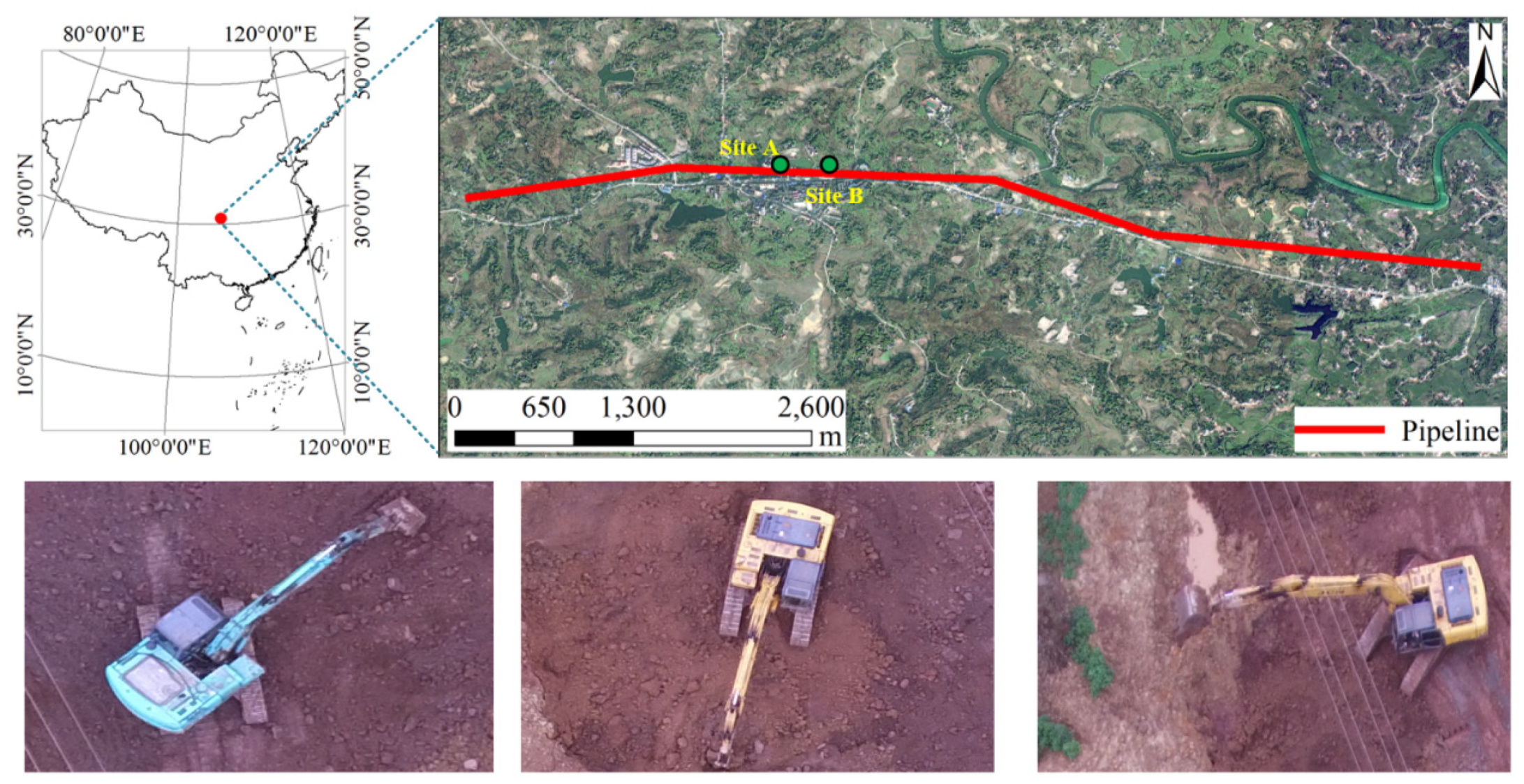
2. Materials
2.1. Dataset
2.2. Instruments
2.3. Unmanned Aerial Vehicle (UAV) Remote-Sensing Experiment
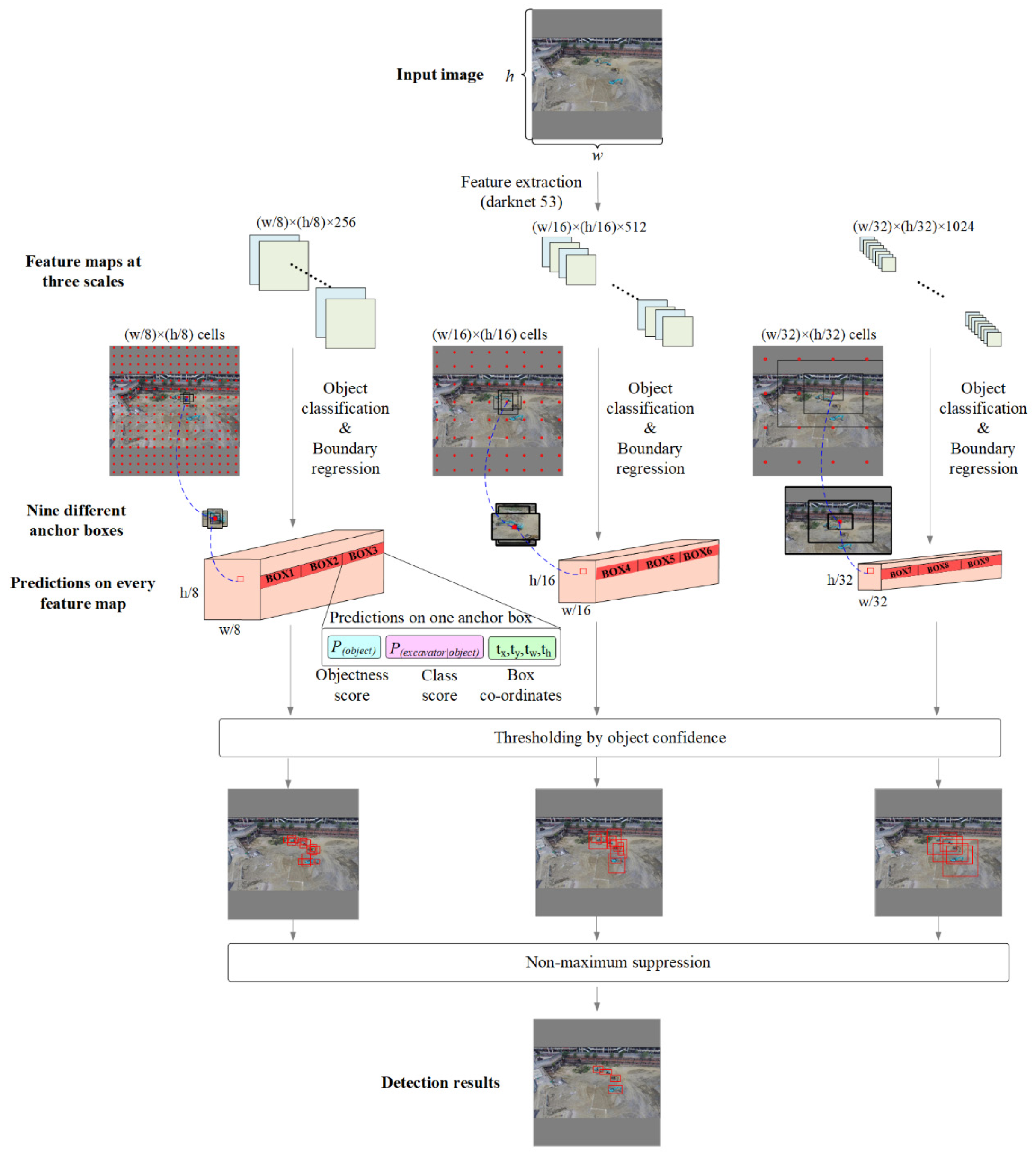
3. Methodology
3.1. The Excavator Detection Model
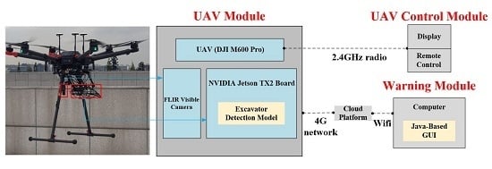
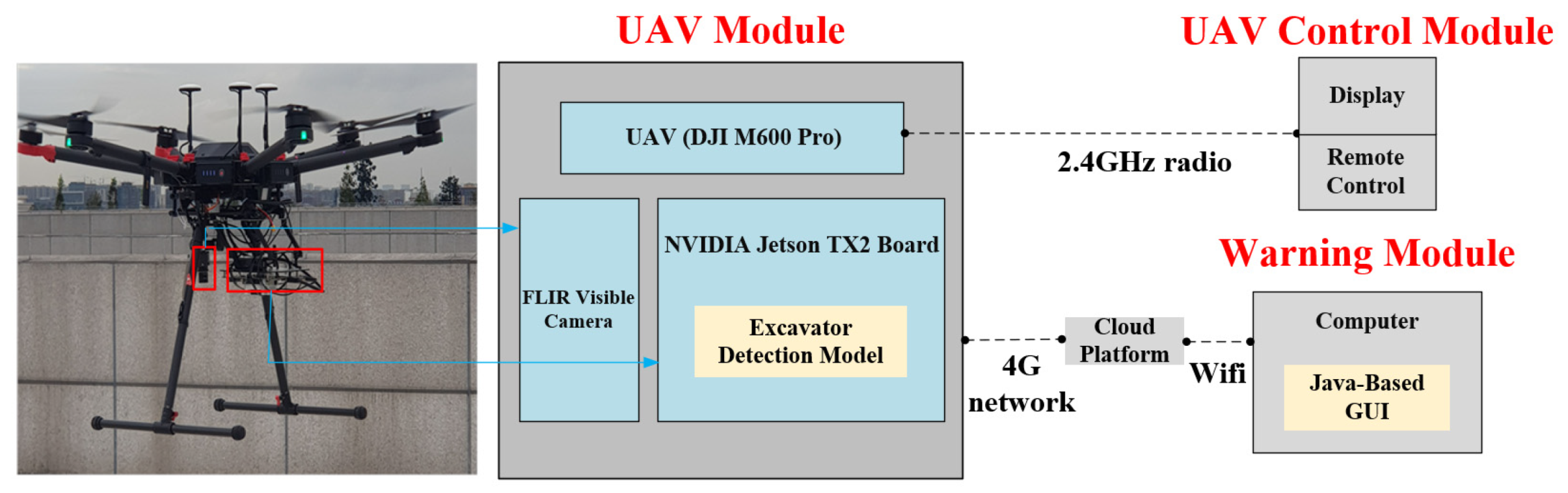
3.2. Construction of the UAV for Excavator Detection (UAV-ED) System
3.2.1. Integration of the Excavator Detection Model, Sensor and UAV
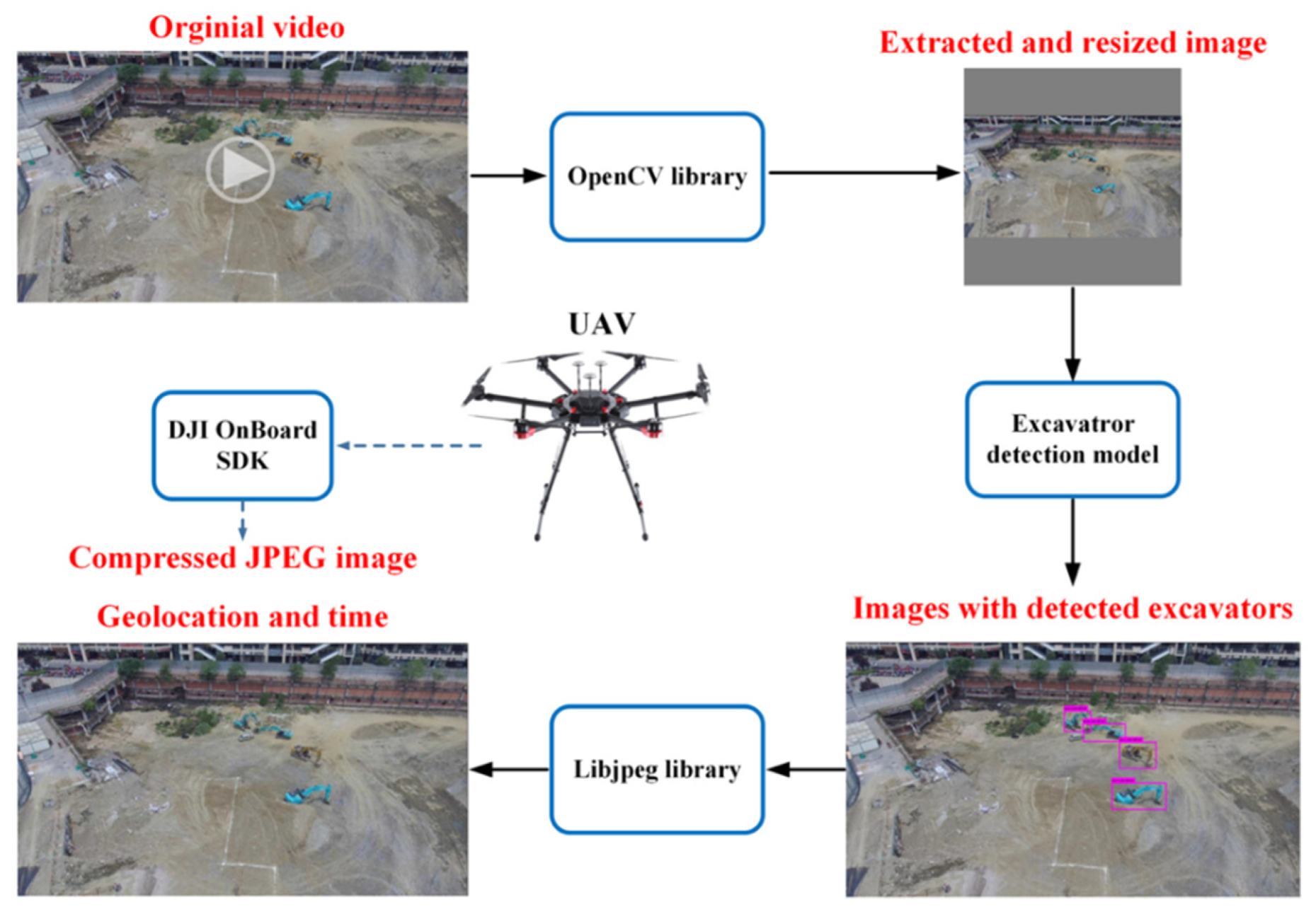
3.2.2. Real-Time Transmission of the Detected Excavators’ Information
4. Results
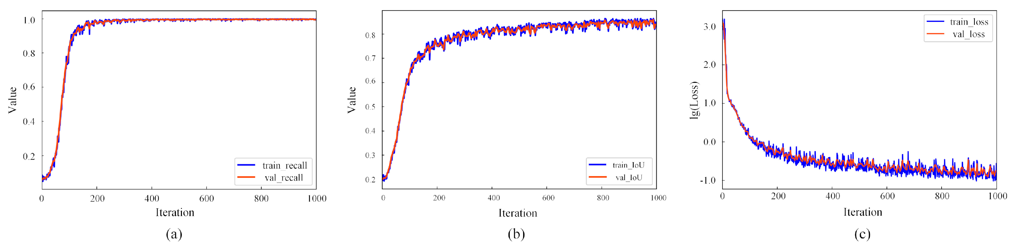
4.1. Performance of the Trained Excavator Detection Model
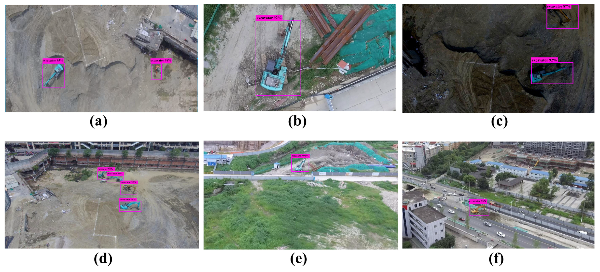
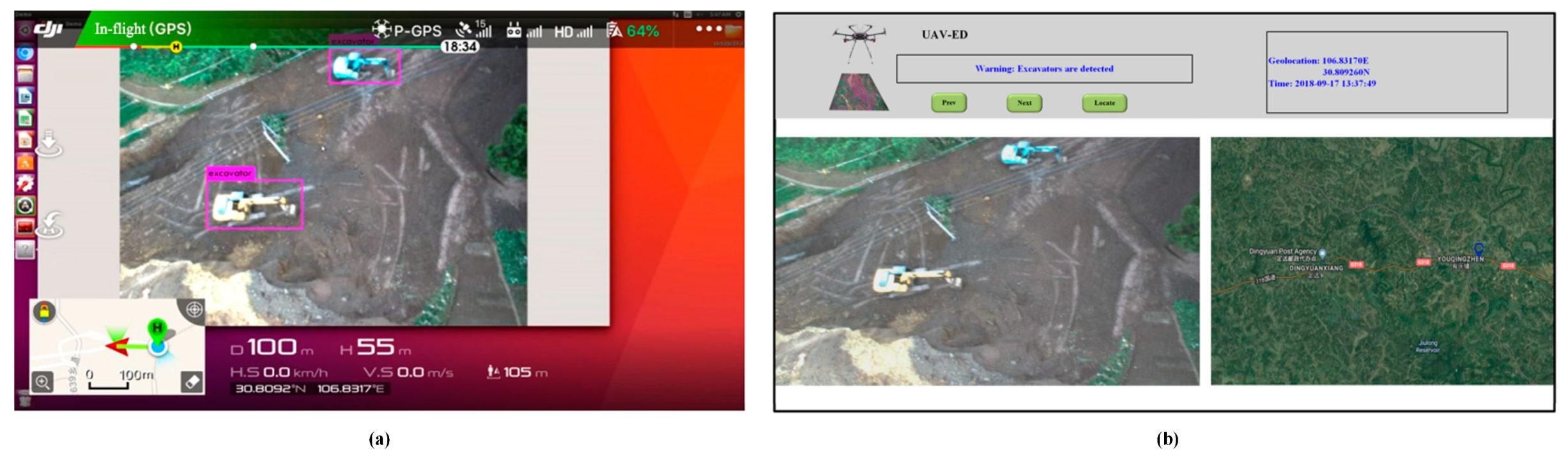
4.2. Performance of the UAV-ED System
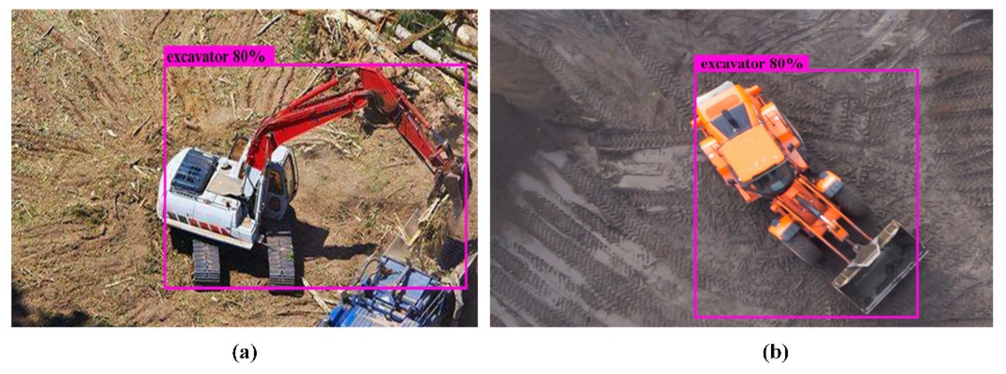
5. Discussion
6. Conclusions
Author Contributions
Funding
Acknowledgments
Conflicts of Interest
References
- Ma, L.; Liu, Y.; Zhang, X.; Ye, Y.; Yin, G.; Johnson, B.A. Deep learning in remote sensing applications: A meta-analysis and review. ISPRS J. Photogramm. Remote Sens. 2019, 152, 166–177. [Google Scholar] [CrossRef]
- Colomina, I.; Molina, P. Unmanned aerial systems for photogrammetry and remote sensing: A review. ISPRS J. Photogramm. Remote Sens. 2014, 92, 79–97. [Google Scholar] [CrossRef] [Green Version]
- Martínez-Carricondo, P.; Agüera-Vega, F.; Carvajal-Ramírez, F.; Mesas-Carrascosa, F.-J.; García-Ferrer, A.; Pérez-Porras, F.-J. Assessment of UAV-photogrammetric mapping accuracy based on variation of ground control points. Int. J. Appl. Earth Obs. Geoinf. 2018, 72, 1–10. [Google Scholar] [CrossRef]
- Wu, Z.; Ni, M.; Hu, Z.; Wang, J.; Li, Q.; Wu, G. Mapping invasive plant with UAV-derived 3D mesh model in mountain area—A case study in Shenzhen Coast, China. Int. J. Appl. Earth Obs. Geoinf. 2019, 77, 129–139. [Google Scholar] [CrossRef]
- Bejiga, M.; Zeggada, A.; Nouffidj, A.; Melgani, F. A Convolutional Neural Network Approach for Assisting Avalanche Search and Rescue Operations with UAV Imagery. Remote Sens. 2017, 9, 100. [Google Scholar] [CrossRef] [Green Version]
- Ballesteros, R.; Ortega, J.F.; Hernandez, D.; del Campo, A.; Moreno, M.A. Combined use of agro-climatic and very high-resolution remote sensing information for crop monitoring. Int. J. Appl. Earth Obs. Geoinf. 2018, 72, 66–75. [Google Scholar] [CrossRef]
- Deng, L.; Mao, Z.; Li, X.; Hu, Z.; Duan, F.; Yan, Y. UAV-based multispectral remote sensing for precision agriculture: A comparison between different cameras. ISPRS J. Photogramm. Remote Sens. 2018, 146, 124–136. [Google Scholar] [CrossRef]
- Madec, S.; Jin, X.; Lu, H.; De Solan, B.; Liu, S.; Duyme, F.; Heritier, E.; Baret, F. Ear density estimation from high resolution RGB imagery using deep learning technique. Agric. For. Meteorol. 2019, 264, 225–234. [Google Scholar] [CrossRef]
- Sofonia, J.; Shendryk, Y.; Phinn, S.; Roelfsema, C.; Kendoul, F.; Skocaj, D. Monitoring sugarcane growth response to varying nitrogen application rates: A comparison of UAV SLAM LiDAR and photogrammetry. Int. J. Appl. Earth Obs. Geoinf. 2019, 82, 101878. [Google Scholar] [CrossRef]
- Kim, I.-H.; Jeon, H.; Baek, S.-C.; Hong, W.-H.; Jung, H.-J. Application of Crack Identification Techniques for an Aging Concrete Bridge Inspection Using an Unmanned Aerial Vehicle. Sensors 2018, 18, 1881. [Google Scholar] [CrossRef] [Green Version]
- Ammour, N.; Alhichri, H.; Bazi, Y.; Benjdira, B.; Alajlan, N.; Zuair, M. Deep Learning Approach for Car Detection in UAV Imagery. Remote Sens. 2017, 9, 312. [Google Scholar] [CrossRef] [Green Version]
- Qu, T.; Zhang, Q.; Sun, S. Vehicle detection from high-resolution aerial images using spatial pyramid pooling-based deep convolutional neural networks. Multimed. Tools Appl. 2017, 76, 21651–21663. [Google Scholar] [CrossRef]
- Zhu, J.; Sun, K.; Jia, S.; Lin, W.; Hou, X.; Liu, B.; Qiu, G. Bidirectional Long Short-Term Memory Network for Vehicle Behavior Recognition. Remote Sens. 2018, 10, 887. [Google Scholar] [CrossRef] [Green Version]
- De Oliveira, D.; Wehrmeister, M. Using Deep Learning and Low-Cost RGB and Thermal Cameras to Detect Pedestrians in Aerial Images Captured by Multirotor UAV. Sensors 2018, 18, 2244. [Google Scholar] [CrossRef] [Green Version]
- Zhang, X.; Chen, G.; Wang, W.; Wang, Q.; Dai, F. Object-Based Land-Cover Supervised Classification for Very-High-Resolution UAV Images Using Stacked Denoising Autoencoders. IEEE J. Sel. Top. Appl. Earth Obs. Remote Sens. 2017, 10, 3373–3385. [Google Scholar] [CrossRef]
- Morales, G.; Kemper, G.; Sevillano, G.; Arteaga, D.; Ortega, I.; Telles, J. Automatic Segmentation of Mauritia flexuosa in Unmanned Aerial Vehicle (UAV) Imagery Using Deep Learning. Forests 2018, 9, 736. [Google Scholar] [CrossRef] [Green Version]
- Gevaert, C.M.; Persello, C.; Nex, F.; Vosselman, G. A deep learning approach to DTM extraction from imagery using rule-based training labels. ISPRS J. Photogramm. Remote Sens. 2018, 142, 106–123. [Google Scholar] [CrossRef]
- Xiang, T.-Z.; Xia, G.-S.; Zhang, L. Mini-UAV-based Remote Sensing: Techniques, Applications and Prospectives. arXiv 2018, arXiv:1812.07770. [Google Scholar]
- Zhao, Y.; Ma, J.; Li, X.; Zhang, J. Saliency Detection and Deep Learning-Based Wildfire Identification in UAV Imagery. Sensors 2018, 18, 712. [Google Scholar] [CrossRef] [Green Version]
- Bah, M.; Hafiane, A.; Canals, R. Deep Learning with Unsupervised Data Labeling for Weed Detection in Line Crops in UAV Images. Remote Sens. 2018, 10, 1690. [Google Scholar] [CrossRef] [Green Version]
- Kerkech, M.; Hafiane, A.; Canals, R. Deep leaning approach with colorimetric spaces and vegetation indices for vine diseases detection in UAV images. Comput. Electron. Agric. 2018, 155, 237–243. [Google Scholar] [CrossRef]
- Kellenberger, B.; Marcos, D.; Tuia, D. Detecting mammals in UAV images: Best practices to address a substantially imbalanced dataset with deep learning. Remote Sens. Environ. 2018, 216, 139–153. [Google Scholar] [CrossRef] [Green Version]
- Kim, D.; Liu, M.; Lee, S.; Kamat, V.R. Remote proximity monitoring between mobile construction resources using camera-mounted UAVs. Autom. Constr. 2019, 99, 168–182. [Google Scholar] [CrossRef]
- Wikipedia. List of Pipeline Accidents. Available online: https://en.wikipedia.org/wiki/List_of_pipeline_accidents (accessed on 10 December 2019).
- EYETRAX. Security Cameras For The Oil And Gas Industries. Available online: https://eyetrax.net/industries/oil-and-gas (accessed on 10 December 2019).
- Khoshboresh Masouleh, M.; Shah-Hosseini, R. Development and evaluation of a deep learning model for real-time ground vehicle semantic segmentation from UAV-based thermal infrared imagery. ISPRS J. Photogramm. Remote Sens. 2019, 155, 172–186. [Google Scholar] [CrossRef]
- Liu, X.; Yang, T.; Li, J. Real-Time Ground Vehicle Detection in Aerial Infrared Imagery Based on Convolutional Neural Network. Electronics 2018, 7, 78. [Google Scholar] [CrossRef] [Green Version]
- Loquercio, A.; Maqueda, A.I.; del-Blanco, C.R.; Scaramuzza, D. DroNet: Learning to Fly by Driving. IEEE Robot. Autom. Lett. 2018, 3, 1088–1095. [Google Scholar] [CrossRef]
- Nex, F.; Duarte, D.; Steenbeek, A.; Kerle, N. Towards Real-Time Building Damage Mapping with Low-Cost UAV Solutions. Remote Sens. 2019, 11, 287. [Google Scholar] [CrossRef] [Green Version]
- Tijtgat, N.; Van Ranst, W.; Volckaert, B.; Goedeme, T.; De Turck, F. Embedded Real-Time Object Detection for a UAV Warning System. In Proceedings of the 2017 Ieee International Conference on Computer Vision Workshops (iccvw 2017), Venice, Italy, 22–29 October 2017; IEEE: New York, NY, USA, 2017; pp. 2110–2118, ISBN 978-1-5386-1034-3. [Google Scholar]
- Hossain, S.; Lee, D. Deep-Learning Based Real-Time Multiple-Object Detection and Tracking from Aerial Imagery via Flying Robot with GPU-based Embedded Devices. Sensors 2019, 15, 3371. [Google Scholar] [CrossRef] [Green Version]
- Skydio Support. Skydio 2 Help. Available online: https://support.skydio.com/hc/en-us (accessed on 10 December 2019).
- DJI. DJI. Available online: https://www.dji.com/cn (accessed on 10 December 2019).
- The Little Ripper Life Sver. The Little Ripper. Available online: https://thelittleripper.com.au (accessed on 10 December 2019).
- Github. LabelImg. Available online: https://github.com/tzutalin/labelImg (accessed on 10 December 2019).
- 10086. Iot. Available online: https://open.iot.10086.cn (accessed on 10 December 2019).
- Du, J.; Guo, J.; Xu, D.; Huang, Q. A Remote Monitoring System of Temperature and Humidity Based on OneNet Cloud Service Platform. In Proceedings of the 2017 IEEE Electrical Design of Advanced Packaging and Systems Symposium (EDAPS), Haining, China, 14–16 December 2017. [Google Scholar]
- Girshick, R.; Donahue, J.; Darrell, T.; Malik, J. Rich feature hierarchies for accurate object detection and semantic segmentation. arXiv 2013, arXiv:1311.2524. [Google Scholar]
- Girshick, R. Fast R-CNN. arXiv 2015, arXiv:1504.08083. [Google Scholar]
- Ren, S.; He, K.; Girshick, R.; Sun, J. Faster R-CNN: Towards Real-Time Object Detection with Region Proposal Networks. arXiv 2015, arXiv:1506.01497. [Google Scholar] [CrossRef] [PubMed] [Green Version]
- Redmon, J.; Divvala, S.; Girshick, R.; Farhadi, A. You Only Look Once: Unified, Real-Time Object Detection. arXiv 2015, arXiv:1506.02640. [Google Scholar]
- Liu, W.; Anguelov, D.; Erhan, D.; Szegedy, C.; Reed, S.; Fu, C.-Y.; Berg, A.C. SSD: Single Shot MultiBox Detector. arXiv 2016, arXiv:1512.02325. [Google Scholar]
- Redmon, J.; Farhadi, A. YOLOv3: An Incremental Improvement. arXiv 2018, arXiv:1804.02767. [Google Scholar]
- Zhang, X.; Yang, W.; Tang, X.; Liu, J. A Fast Learning Method for Accurate and Robust Lane Detection Using Two-Stage Feature Extraction with YOLO v3. Sensors 2018, 18, 4308. [Google Scholar] [CrossRef] [PubMed] [Green Version]
- Darket. YOLO. Available online: https://pjreddie.com/darknet/yolo (accessed on 10 December 2019).
- Bradski, G. The OpenCV Library. IEEE Robot. Autom. Mag. 2009, 16, 100. [Google Scholar]
- Opencv. Opencv. Available online: https://opencv.org (accessed on 10 December 2019).
- JPEG. Libjpeg. Available online: http://libjpeg.sourceforge.net (accessed on 10 December 2019).
- DJI. Developer. Available online: https://developer.dji.com (accessed on 10 December 2019).
- Tian, Y.; Yang, G.; Wang, Z.; Wang, H.; Li, E.; Liang, Z. Apple detection during different growth stages in orchards using the improved YOLO-V3 model. Comput. Electron. Agric. 2019, 157, 417–426. [Google Scholar] [CrossRef]
- COCO Dataset. Available online: http://mscoco.org (accessed on 10 December 2019).
- Long, J.; Shelhamer, E.; Darrell, T. Fully Convolutional Networks for Semantic Segmentation. In Proceedings of the 2015 IEEE Conference on Computer Vision and Pattern Recognition (CVPR), Boston, MA, USA, 8–10 June 2015. [Google Scholar]
- Lin, T.-Y.; Goyal, P.; Girshick, R.; He, K.; Dollár, P. Focal Loss for Dense Object Detection. arXiv 2018, arXiv:1708.02002. [Google Scholar] [CrossRef] [Green Version]
- Zhang, H.; Yang, W.; Yu, H.; Zhang, H.; Xia, G.-S. Detecting Power Lines in UAV Images with Convolutional Features and Structured Constraints. Remote Sens. 2019, 11, 1342. [Google Scholar] [CrossRef] [Green Version]
- Yuan, C.; Liu, Z.; Zhang, Y. Learning-Based Smoke Detection for Unmanned Aerial Vehicles Applied to Forest Fire Surveillance. J. Intell. Robot. Syst. 2019, 93, 337–349. [Google Scholar] [CrossRef]
- Badrinarayanan, V.; Kendall, A.; Cipolla, R. SegNet: A Deep Convolutional Encoder-Decoder Architecture for Image Segmentation. arXiv 2015, arXiv:1511.00561. [Google Scholar] [CrossRef] [PubMed]
- Ronneberger, O.; Fischer, P.; Brox, T. U-Net: Convolutional Networks for Biomedical Image Segmentation. arXiv 2015, arXiv:1505.04597. [Google Scholar]
- Xia, G.-S.; Bai, X.; Ding, J.; Zhu, Z.; Belongie, S.; Luo, J.; Datcu, M.; Pelillo, M.; Zhang, L. DOTA: A Large-scale Dataset for Object Detection in Aerial Images. arXiv 2017, arXiv:1711.10398. [Google Scholar]


| Instrument | Model | Specification |
|---|---|---|
| Unmanned aerial vehicle (UAV) | DJI M600 Pro | Six rotors Image transmission module: DJI LightBridge 2 Flight time: 38 min with no load Maximum horizontal velocity: 18 m/s Load capacity: maximum 6 kg |
| Sensor | FLIR BFLY-U3-13S2C-CS | Resolution: 1288 × 964 pixels Size: 29 × 29 × 30 mm Weight: 36 g Frame rate: 30 frames per second |
| Embedded board | NVIDIA Jetson TX2 | Graphics Processing Unit (GPU): an NVIDIA Pascal™-family GPU Memory: 8 GB Memory bandwidth: 59.7 GB/s Power consumption: 7.5 watt Support hardware interfaces: Universal Serial Bus and High Definition Multimedia Interface |
| Tablet | Apple iPad mini 4 | - |
| Computer | Microsoft Surface Pro 4 | - |
| Batch Size | Momentum | Decay | Learning Rate |
|---|---|---|---|
| 64 | 0.9 | 0.0005 | 0.0001 |
| Dataset | Recall Rate | Precision | Accuracy | IoU |
|---|---|---|---|---|
| train | 99.8% | 98.3% | 98.0% | 84.4% |
| validation | 99.4% | 98.0% | 97.4% | 83.7% |
| test | 99.4% | 97.7% | 97.2% | 83.1% |
| Resolutions | Processing Speed (FPS) | Detection Accuracy | |||
|---|---|---|---|---|---|
| Computer | Jetson TX2 | Recall | IoU | Loss | |
| 416 × 416 | 47 | 3.7 | 99.4% | 83.7% | 0.152 |
| 384 × 384 | 50 | 4.3 | 98.3% | 82.3% | 0.155 |
| 352 × 352 | 52 | 4.9 | 97.5% | 81.0% | 0.158 |
| 320 × 320 | 58 | 5.4 | 96.8% | 79.2% | 0.165 |
| 288 × 288 | 60 | 5.9 | 96.5% | 78.9% | 0.167 |
| Flight | Site | Number of Images | Duration (s) | Speed (s) |
|---|---|---|---|---|
| I | A | 86 | 96 (10:47:17–10:48:53) | 1.11 |
| B | 70 | 72 (10:50:26–10:51:38) | 1.02 | |
| II | A | 148 | 173 (13:38:44–13:41:37) | 1.16 |
| B | 124 | 151 (13:45:32–13:48:03) | 1.21 | |
| Overall | 428 | 492 s | 1.15 | |
| Inspection | Cost (×10,000 RMB) | ||||
|---|---|---|---|---|---|
| Labor | Electricity | Communication | Equipment Depreciation | Total | |
| Manual | 28 | 0.1 | 0.5 | 0.4 | 29.0 |
| UAV | 4 | 0.5 | 0.1 | 9.5 | 14.1 |
© 2020 by the authors. Licensee MDPI, Basel, Switzerland. This article is an open access article distributed under the terms and conditions of the Creative Commons Attribution (CC BY) license (http://creativecommons.org/licenses/by/4.0/).
Share and Cite
Meng, L.; Peng, Z.; Zhou, J.; Zhang, J.; Lu, Z.; Baumann, A.; Du, Y. Real-Time Detection of Ground Objects Based on Unmanned Aerial Vehicle Remote Sensing with Deep Learning: Application in Excavator Detection for Pipeline Safety. Remote Sens. 2020, 12, 182. https://0-doi-org.brum.beds.ac.uk/10.3390/rs12010182
Meng L, Peng Z, Zhou J, Zhang J, Lu Z, Baumann A, Du Y. Real-Time Detection of Ground Objects Based on Unmanned Aerial Vehicle Remote Sensing with Deep Learning: Application in Excavator Detection for Pipeline Safety. Remote Sensing. 2020; 12(1):182. https://0-doi-org.brum.beds.ac.uk/10.3390/rs12010182
Chicago/Turabian StyleMeng, Lingxuan, Zhixing Peng, Ji Zhou, Jirong Zhang, Zhenyu Lu, Andreas Baumann, and Yan Du. 2020. "Real-Time Detection of Ground Objects Based on Unmanned Aerial Vehicle Remote Sensing with Deep Learning: Application in Excavator Detection for Pipeline Safety" Remote Sensing 12, no. 1: 182. https://0-doi-org.brum.beds.ac.uk/10.3390/rs12010182