Technical Note

The Use of USV to Develop Navigational and Bathymetric Charts of Yacht Ports on the Example of National Sailing Centre in Gdańsk

1
Department of Transport and Logistics, Gdynia Maritime University, Morska 81-87, 81-225 Gdynia, Poland
2
Department of Geodesy and Oceanography, Gdynia Maritime University, Morska 81-87, 81-225 Gdynia, Poland
3
Gdańsk University of Physical Education and Sport, Kazimierza Górskiego 1, 80-336 Gdańsk, Poland
4
Department of Navigation and Hydrography, Polish Naval Academy, Śmidowicza 69, 81-127 Gdynia, Poland
5
Department of Marine Electronic Systems, Gdańsk University of Technology, 11/12 Gabriela Narutowicza, 80-233 Gdańsk, Poland
*
Author to whom correspondence should be addressed.
Remote Sens. 2020, 12(16), 2585; https://0-doi-org.brum.beds.ac.uk/10.3390/rs12162585
Submission received: 30 June 2020 / Revised: 1 August 2020 / Accepted: 10 August 2020 / Published: 11 August 2020

Abstract

:
Apart from extensive infrastructure protection, modern yacht ports should primarily provide vessels with navigational safety associated with their maneuvering on the approach fairway, as well as mooring in the port aquatory. For this reason, yachts entering the harbor should have up-to-date, accurate, and reliable charts of the port and its surroundings. This article presents hydrographic surveys conducted in the National Sailing Centre (NSC) yacht port at the Gdańsk University of Physical Education and Sport (GUPES), whose aim was to define and develop unique bathymetric and navigational charts of the harbor and the approach fairway. These can be used for example to manage berths in the marina or inform about the depths in the yacht port and on the approach fairway. The chart of the NSC-GUPES and its approach fairway is Poland’s first cartographic image of a harbor, performed entirely on the basis of surveys conducted by an Unmanned Surface Vehicle (USV). The study results demonstrated that the use of a small-sized USV in bathymetric measurements of yacht ports and marinas was significantly more effective than the traditional (manned) hydrographic surveys. Such vessels allow measurements to be carried out in hard-to-reach locations, even between mooring vessels, and in the immediate vicinity of quays. Thanks to the implemented automatic mode of steering on sounding profiles, USVs are equally efficient and capable of carrying out hydrographic surveys on a larger waterbody, i.e., the approach fairway.

Graphical Abstract

1. Introduction

In terms of navigation safety, yacht ports and marinas, unlike sea and inland harbors, are characterized by the presence of shoal, variable and varying depths (3–5 m), and are devoid of systems for the continuous measurement of water level. Both of these factors adversely affect the safety of maneuvering and mooring of sailing or motor vessels in marinas.
As one approaches the restricted area, bathymetric measurements are carried out using small ships [1,2]. Typical hydrographic vessels carry out bathymetric measurements in open waterbodies, at great depths and in the daily or multi-day surveys, in accordance with the commonly known methodology [3,4,5] and execution standards [6,7]. In the coastal area, bays, and major harbor basins, measurements are carried out using hydrographic cutters and motorboats whose size often hinders their free maneuvering within a marina, particularly where other vessels are at berth [8,9]. For this reason, it is reasonable to consider the use of small-sized Unmanned Surface Vehicles (USVs) for the depth measurements of small inland and sea yacht ports or marinas. USVs are defined as unmanned vehicles that perform tasks in a variety of cluttered environments without any human intervention, and essentially exhibit highly nonlinear dynamics [10].
At the beginning of the 21st century, there was a rapid development of vessels, aimed at their complete autonomy [11]. In parallel, small-sized unmanned vessels used in a variety of surveying applications [12,13], including hydrography, are being currently developed. Modern autonomous and unmanned surface vehicles are design solutions that differ significantly from one another, mainly in the size, design of the hull, and the type of propulsion. Single- or multi-hulled vessels with a screw or screwless propulsion are commonly used in coastal and harbor areas [14]. Their particular common feature is a small draft that allows them to enter a hard-to-reach waterbody, including those with a shallow depth (less than 1 m) [15,16]. For this reason, the use of small-sized unmanned vessels in both marine and inland hydrography [17] is nowadays becoming increasingly widespread. Currently, the areas in which USVs are used include scientific research [18,19,20], environmental missions [21], ocean resource exploration [22], military uses, and other applications [23].
USVs have greater potential payload capacity and endurance than comparably-sized unmanned systems in other domains. They are able to use higher-density energy sources than Unmanned Underwater Vehicles (UUVs) (hydrocarbons instead of batteries), and, unlike Unmanned Aerial Vehicles (UAVs), they do not need to burn fuel merely to maintain their vertical position; if desired, they can move relatively slowly for days or weeks without refueling [24]. Figure 1 presents examples of three types of unmanned vessels capable of performing hydrographic survey tasks, which significantly differ in the equipment and capabilities. The first is a multi-purpose vessel, the XOCEAN XO-450 (weight of 750 kg, payload of 100 kg, speed of 3.5–7 kn, range of 1512 Nm, equipment: multibeam bathymetry, fisheries research sonars, acoustic modems, and environmental sensors), capable of carrying out a multi-day mission in autonomous mode, even in the open sea. Another vessel is the HydroDron manufactured by the Marine Technology Ltd. (weight of 300 kg, payload of 100 kg, max speed of 10 kn, range of 50 Nm, equipment: sonar system, SBES, SVP, LiDAR, INS, radar, weather station, and GNSS receiver), which has the potential to carry out hydrographic surveys in coastal and inland waterbodies. The latter of the vessels is the Hydrone manufactured by the Seafloor Systems Inc. (weight of 9.8 kg, payload of 15 kg, max speed of 6 kn, range of 1 Nm, equipment: GNSS receiver and SBES), whose size, design, and equipment are well-suited for maneuvering within narrow harbor basins and between other vessels; it is equipped with a Single Beam Echo Sounder (SBES) and a positioning system that meets the highest requirements of the International Hydrographic Organization (IHO) S-44 standard [7,25].
Apart from the need to have up-to-date navigational charts of the interior and approach fairway, yacht ports provide a range of services to yachts present in their basin. Hence, they should also provide users with information concerning the current water level, the organization of berths, the location of electricity and water intake points, the possibility for acquiring fuel, infrastructure protection, the availability of medical facilities, etc. For this reason, each marina should have its own special purpose, with a thematic map that presents the infrastructure and services of a yacht port in a simple and understandable way. A thematic map is a map that shows several or one selected component of the natural environment, or a specific area of socio-economic life. A feature that distinguishes such maps from geographic maps is their thematic scope. The base content of thematic maps often includes selected components of geographic maps [26]. With regards to thematic maps of yacht ports, they should present those selected elements that are related to the general functioning of marinas. They should, therefore, include both navigation conditions and other components and services of the harbor, which are of significance to their users. A particularly important factor that affects the readability of a thematic map of a marina is the appearance of icons that symbolize particular components and services of infrastructure.
This paper is organized as follows. Section 2 shows how the measurement equipment were used during the surveys. In addition, this chapter presents the research site in the National Sailing Centre (NSC) yacht port at the Gdańsk University of Physical Education and Sport (GUPES), and the measurement concept. Section 2 also describes how the hydrographic surveys using an USV, as well as supplementary bathymetric and geodetic measurements were conducted. In Section 3, a unique bathymetric and navigational charts of the harbor and the approach fairway for various needs were defined and developed. Section 4 demonstrates the actual research in the field of seabed surveys in the port areas. Finally, general conclusions are discussed in Section 5.

2. Materials and Methods

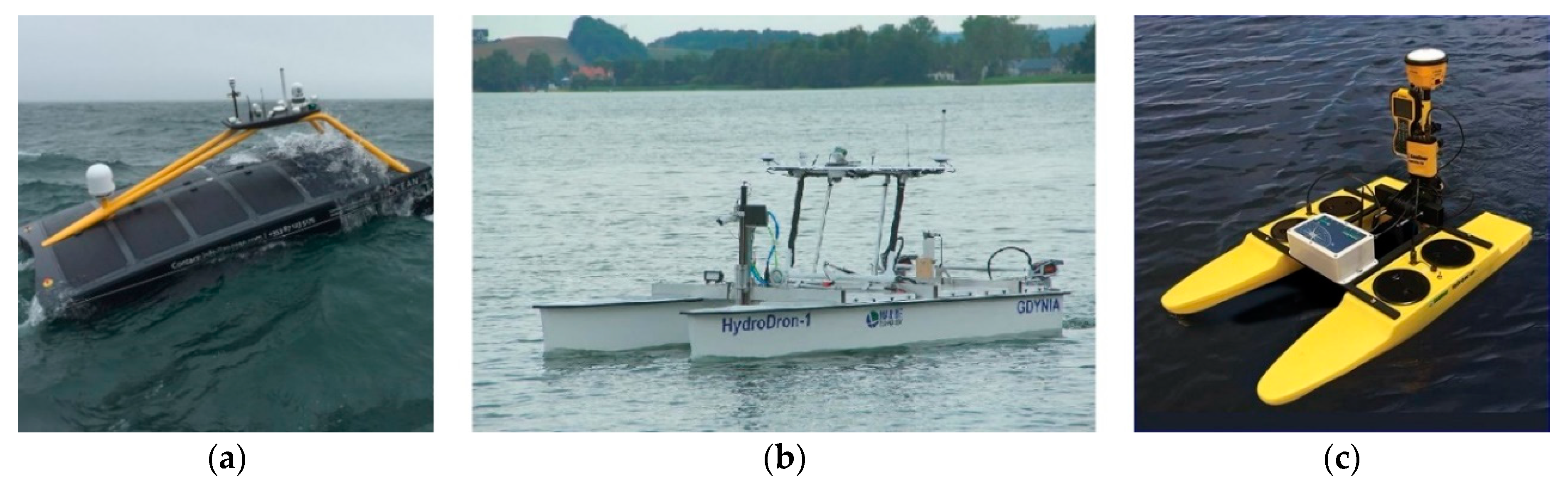
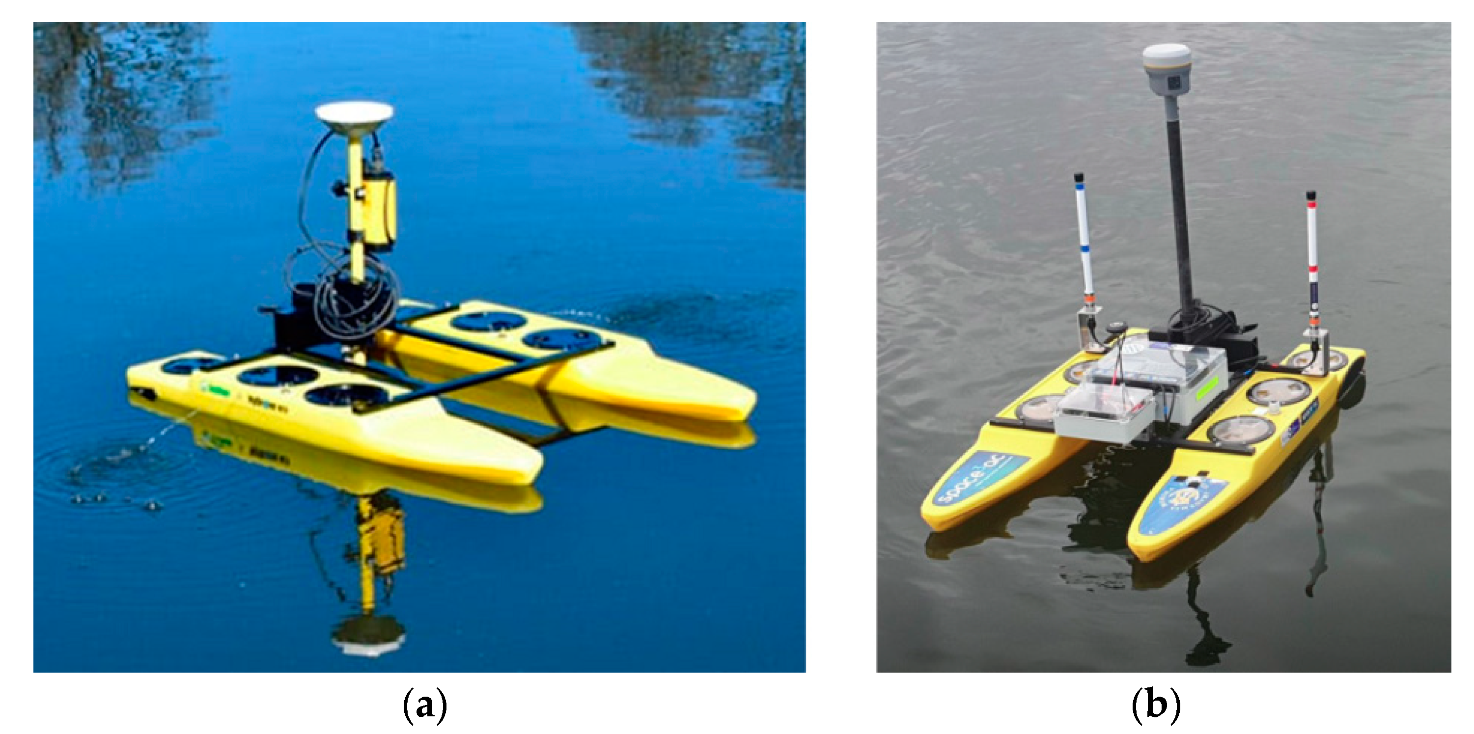
2.1. Measurement Equipment

Bathymetric measurements of the yacht port used a small-sized survey vessel manufactured by the Seafloor Systems Inc. (Shingle Springs, CA, USA). It has a length of 1.1 m and a width of 0.7 m, with a total weight of approximately 18 kg. The USV belongs to the X class in accordance with the adopted global American nomenclature [27]. It was modernized to allow the mission (sailing on sounding profiles) to be carried out in automatic mode (Figure 2). The USV modernization concerned the following components—a PixHawk Cube autopilot was installed; a Radio Control (RC) microwave transmission was modernized to increase the operation range by three times; for the autopilot control, a low-cost multi-GNSS (Global Navigation Satellite System) receiver (u-blox NEO-M8N) with a built-in Fluxgate compass was used; the drive system was replaced and its power was increased (2 × 50 N); the previously used AGM batteries (2 × 10⁸ Wh) were replaced by LiPo batteries (2 × 326 Wh) to increase the time of operation by four times, while reducing the weight by 28% [28].
The USV was equipped with hydrographic equipment comprising a SonarMite hydrographic SBES, operating at a frequency of 200 kHz, and a Trimble R10 GNSS receiver operating in the VRSNet.pl network, at a frequency of 1 Hz, thus ensuring a real-time horizontal positioning accuracy of 2 cm (p = 0.95) [29]. After the mounting of all measuring devices on the USV, the sensors were calibrated to verify their correct operation and to eliminate errors. Therefore, for an SBES, three operations were performed [30,31]:
  • Calibration (taring) of the vertical echo sounder.
  • Measurement of the vertical distribution of the speed of sound in water.
  • Measurement of the draft of the echo sounder transducer.
However, for the GNSS receiver, the following operations were carried out:
  • Inclinometer calibration.
  • Magnetometer calibration.
Another marine vessel that was used in the research was the hydrographic survey motorboat Navigator One AMG (Figure 3), a manned vessel intended for carrying out hydrographic surveys, with a length of 5.5 m, width of 2.55, draft of 0.3 m, a crew of 6, coastal buoyancy class, and a weight of 780 kg. It was equipped with an outboard motor with a power of 115 hp (Suzuki) and the Lowrance HDS Carbon navigation system, with the StructureScan 3D module. The task of the vessel was to provide the unmanned vessel’s operation with supervision, particularly during surveys of the water area adjacent to the harbor.
Oceanographic measurements that are part of hydrographic surveys include water level observations and measurements of the speed of sound in water. The water level can be observed on a gauging station, which is situated in a marina or port and is referenced to the geodetic height system used in a particular country. In Poland, according to the current regulations [32], water levels are referenced to the height system of Kronstadt (PL-KRON86-NH), (up to 2023) and Amsterdam (PL-EVRF2007-NH). For the area of NSC surveys, the actual water level was calculated on the basis of the arithmetic mean of the readings from the two closest gauging stations located on the Gdańsk Górki Zachodnie and Gdańsk Port Północny. After this was determined, it was possible to refer the measured depths to the so-called chart datum, which for the PL-KRON86-NH height system, amounted to 508 cm [33,34]. To do so, the following formula should be used:
d = ( d + Δ d E T ± Δ d C D )
where:
  • d —normal height of the point measured by the echo sounder in the PL-KRON86-NH height system (cm),
  • d —depth measured by the echo sounder (cm),
  • Δ d E T —draft of the echo sounder transducer (cm),
  • Δ d C D —a depth correction referred to the chart datum in the PL-KRON86-NH height system (cm), which needs to be added where the averaged sea level ( d ¯ S L ) does not exceed 508 cm; otherwise, it needs to be subtracted.
The correction Δ d C D , which is determined based on the following equation, requires additional explanation:
Δ d C D = 508   c m d ¯ S L
where:
d ¯ S L —averaged sea level observed on a tide gauge between consecutive full hours in the PL-KRON86-NH height system (cm). It can be determined based on the data provided by the Institute of Meteorology and Water Management-National Research Institute (IMGW–PIB) weather service.

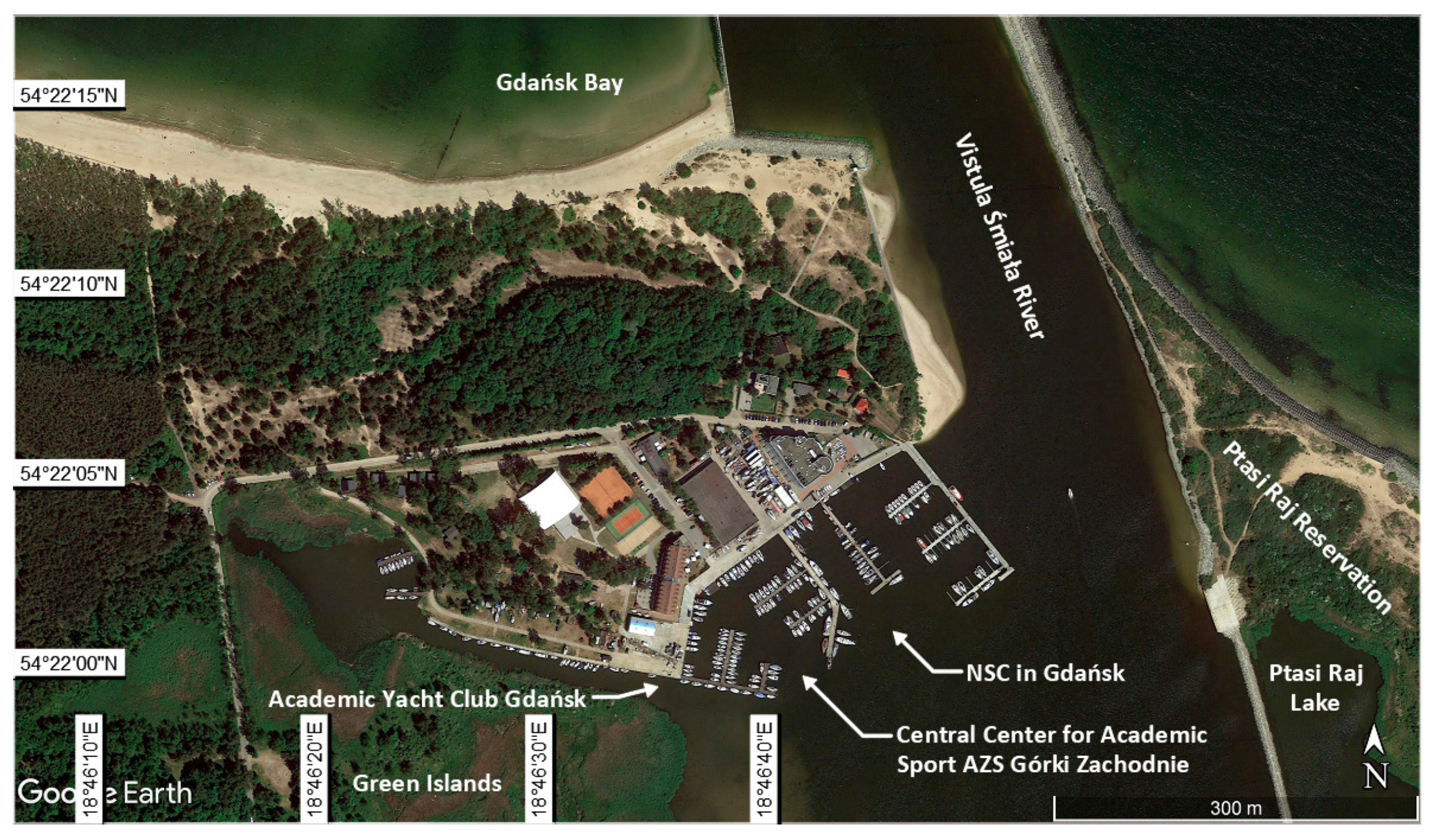
2.2. Measurement Site

In order to assess the possibility of using an USV to develop navigational charts, the NSC yacht port at the GUPES, i.e., the main Olympic sailing training center, was selected. It is located on the eastern (left) shore of the Vistula Śmiała River mouth, which formed natural backwater in that place (Figure 4). NSC-GUPES, together with the Central Center for Academic Sport AZS Górki Zachodnie and the Academic Yacht Club Gdańsk, forms a complex of yacht ports located in the southern part of the Gdańsk district of Górki Zachodnie, which is situated 12 km from the Gdańsk city center.
Thanks to the excellent location and the possibility to select an internal (backwater of the Vistula Śmiała River) or external waterbody (the Gdańsk Bay), the yacht port is primarily used as a place for practical sailing training for GUPES students (including the instructor and coaching training), training facility for the sailing training, including the sailing section AZS at the GUPES, clubs and associations from all over Poland, inter alia the Polish Yachting Association, and the World Sailing. It is the site of water sports education for sailing classes from the Gdańsk School of the Sports Championship, practical training for students of the Maritime School Complex in Gdańsk, the sailing section of the University of Gdańsk and the local organization of the Nationwide Sailing Education Programme PolSailing. It is the main center for coach and supplementary training, as well as for improving the work of sailing instructors and jurors, a place for the organization of numerous sailing projects and events, primarily the Poland’s sailing championship for Olympic classes. Every year, international training courses are organized here and these are also addressed to sailors with disabilities, since the facility is fully adapted to their needs. Private yachts are also stationed there. The yacht port is localized in the northern part of the Vistula Śmiała River backwater. In the harbor, yachts moor to the permanent quay of one of four floating platforms. The marina offers 100 berths. In the marina, yachts moor to berths designated by the so-called y-booms, and cleats along the permanent quay or to buoys anchored in the harbor basin.
The Vistula Śmiała River is the central part of the Vistula River’s mouth to the Gdańsk Bay. The entrance to the river is protected from the east by a breakwater with a length of 520 m, whose extension to the south is a dyke that separates the backwater (Ptasi Raj Lake) on the eastern side of the river, and from the west, a groyne with a length of 160 m. In the middle of the entrance, there is a waterway marked with buoys. The width of the waterway is 35 m, and its depth is 4.5 m. After passing the entrance, the route leads through natural depths to the Vistula Śmiała River (traffic to Gdańsk or the lock in Przegalina). Vessels entering the Vistula Śmiała River should steer towards the left entrance beacon, which needs to be passed on the left side at a distance of no less than 50 m. It is then necessary to sail along the waterway marked with unlit buoys, which, from 1 May to 30 September, are replaced with light buoys. Sports vessels with a draft of more than 2.5 m, steering towards the marina on the Vistula Śmiała River, need to ask harbor masters about the current depths in the marinas, every time. Vessels with a draft of more than 4 m can navigate (all year round), only with the consent of the Gdańsk Harbour Master’s Office (UHF channel 14). During the icing period, navigation can be restricted.
The approach fairway from the Gdańsk Bay side through the Vistula Śmiała cut has no navigation marks in the form of buoys or leading lights. When navigating between the entrance breakwaters towards the Vistula Śmiała River, attention must be paid to shallows situated on the right side of the waterway, i.e., a sandy beach that is the extension of the western breakwater. Directly on the approach fairway to the NSC-GUPES, there are two shallows with a depth of 1.9 and 1.8 m. At a distance of approximately 80 m towards the Vistula Śmiała River from the left entrance beacon, an extensive shoal with a depth of 0.4 m, adjacent to the Green Islands area, is situated. When approaching the harbor, attention must be paid to the significant number of small-sized vessels participating in sailing training.
The NSC-GUPES yacht port comprises two basins. The main entrance (between the platform of the eastern breakwater and the breakwater bordering with the Central Center for Academic Sport AZS Górki Zachodnie) has a width of 111.4 m. The entrance to the eastern basin has a width of 22.7 m and the western basin has a width of 28.7 m. In accordance with the data originating from the Electronic Chart Display and Information System (ECDIS), the eastern basin depth is 3.5–5.1 m, while for the western basin, the depth at the entrance is 3.1 m. In the western basin, a shoal is situated near the crane. Navigation marks on the approach fairway to the NSC-GUPES yacht port are shown in Figure 5.
The basic navigation system available to sailing and motorized vessels entering the Vistula Śmiała River mouth is the Differential Global Positioning System (DGPS), which uses the reference station in Rozewie. A multi-annual study demonstrated that at that time it allowed a positioning accuracy of 2 m (p = 0.95). The second system that is most recommended in terms of the positioning accuracy is the European Geostationary Navigation Overlay Service (EGNOS), with an accuracy of 3 m (p = 0.95) [35].

2.3. Measurement Concept

Hydrographic surveys comprise two basic parts—bathymetric measurements of the seafloor [36] and geodetic measurements of the adjacent land [37,38], in accordance with the global requirements and execution standards [6,7]. As part of the NSC-GUPES surveys, three measurement stages were conducted:
STAGE 1: Geodetic and hydrographic surveys of the yacht port, conducted on 15 April 2019. They included:
  • Bathymetric measurements of the NSC-GUPES yacht port basins using an USV.
  • Inventory geodetic measurements of the quays using a Topcon HiPer II GNSS Receiver with a Sokkia SHC-25 controller operating in the TPI NETpro network, using the NET RTCM 3.0 service with a virtual reference station.
  • Laser scanning of the port infrastructure using a Trimble TX8 laser scanner.
STAGE 2: Hydrographic surveys of the approach fairway, conducted on 2 July 2019. Their aim was to carry out supplementary measurements including bathymetric sounding of the approach fairway, using an USV controlled from a Navigator One AMG vessel.
STAGE 3: Geodetic inventory of the outport navigation marks, with particular emphasis on the extensive shoal found in the vicinity of the Green Islands area. It was conducted on 7 July 2019, and included:
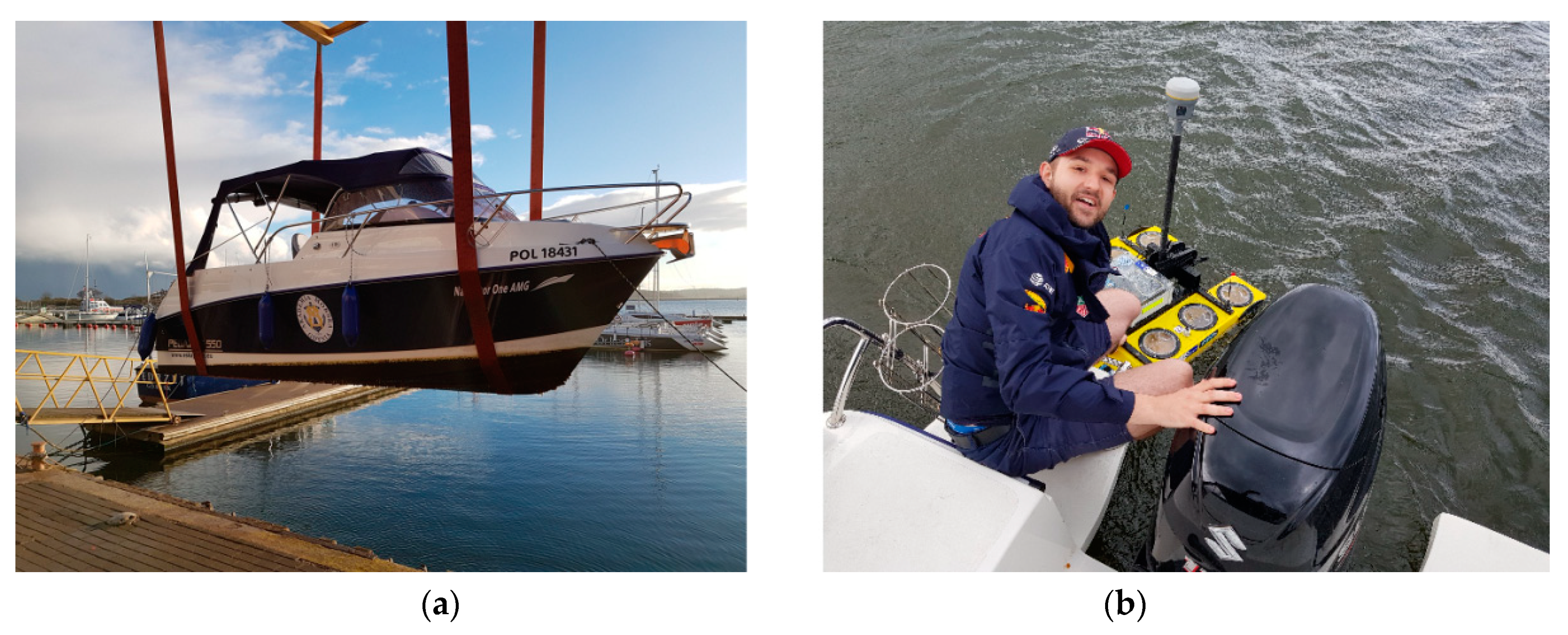
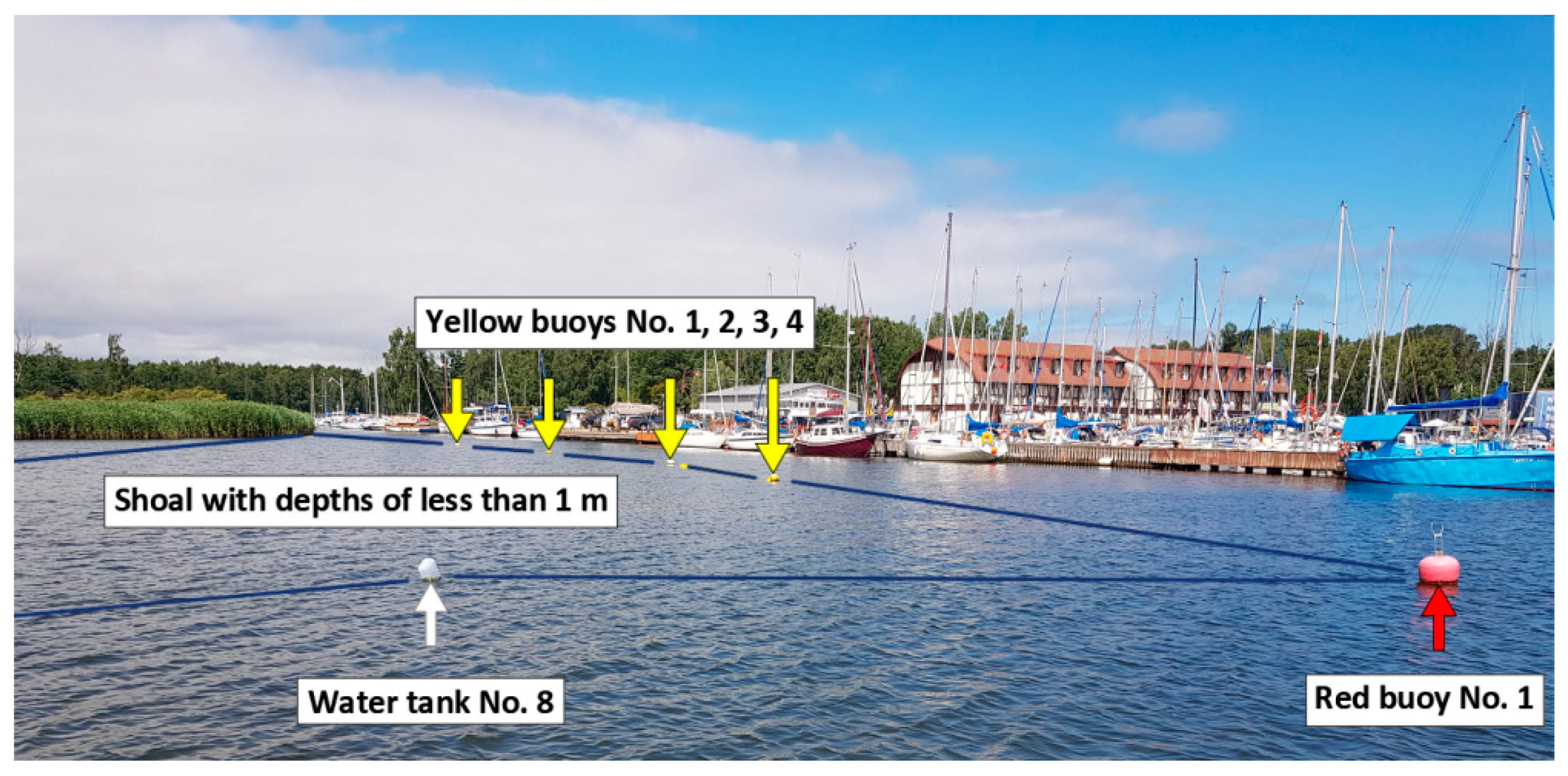
  • Inventory surveys of the navigation marks on the shoal adjacent to the Green Islands, using a Trimble R10 GNSS receiver, as well as the Navigator One AMG vessel.
  • A photographic inventory of the navigation marks in the waterbody, from the entrance beacons to the Vistula Śmiała River, through the approach fairway, along the harbors of the northern part of the backwater.
This publication describes the work aimed at the developing of navigational charts of the yacht port, including bathymetric and geodetic measurements of the marina.

2.4. Measurements

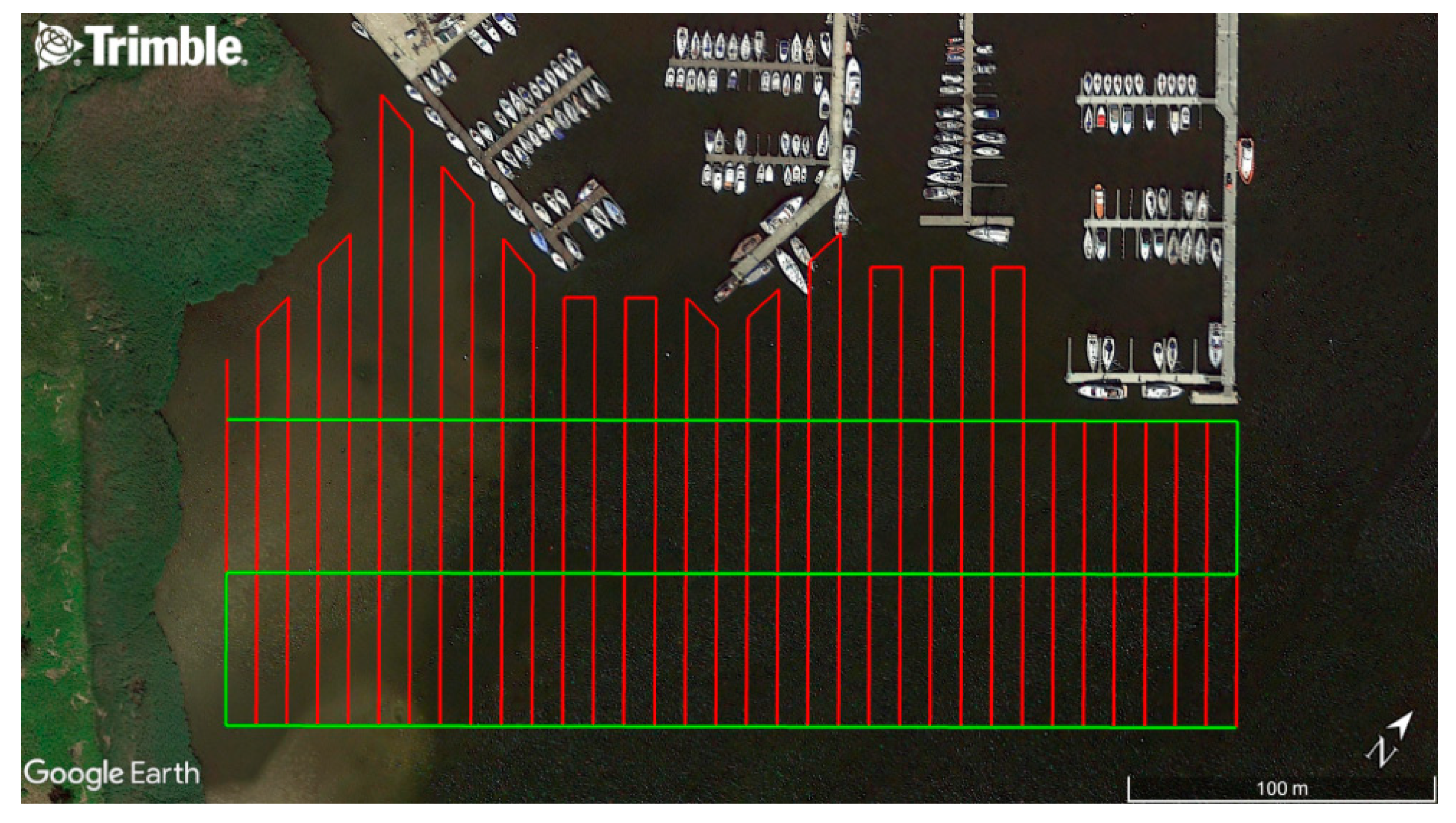
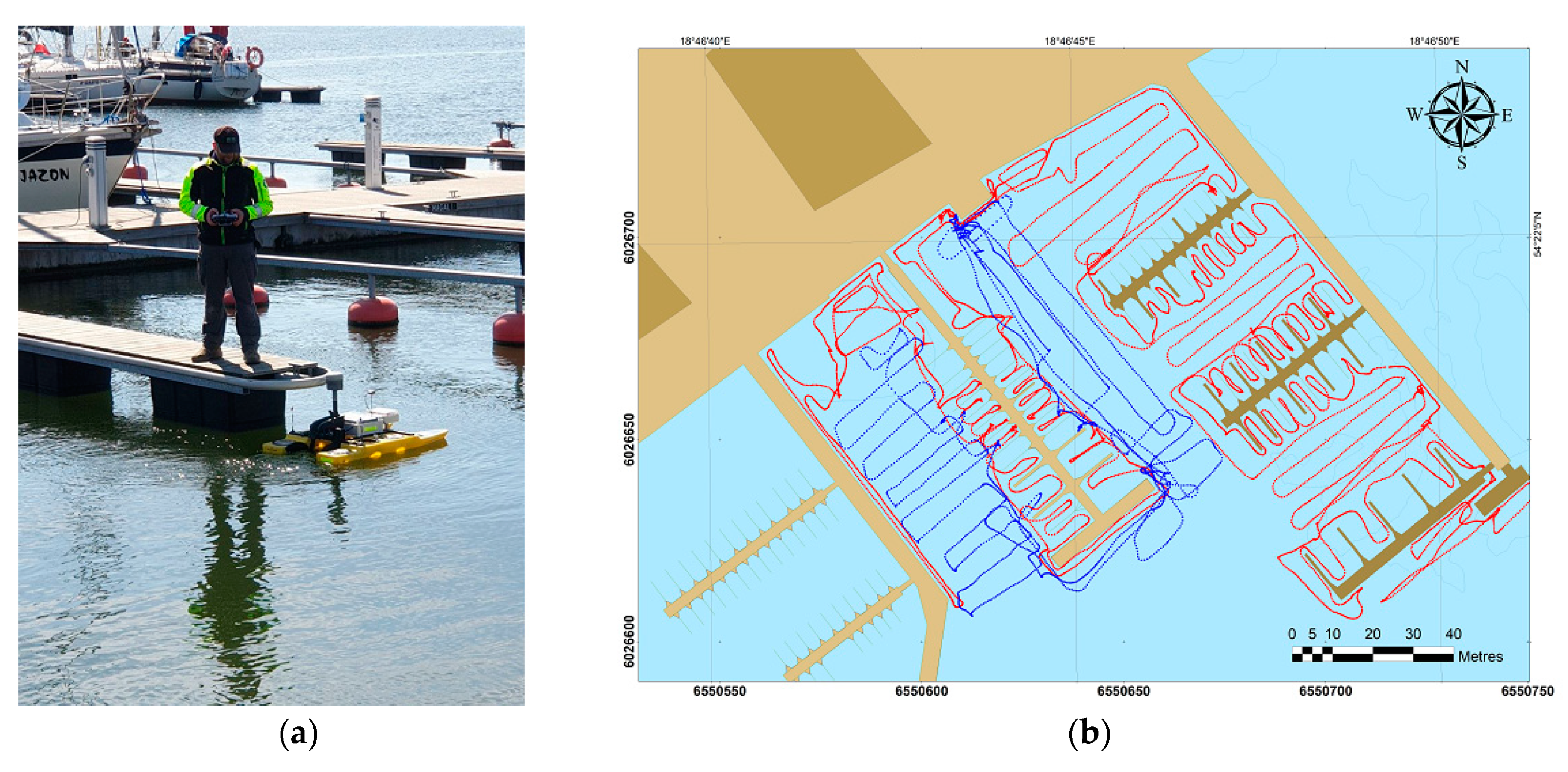
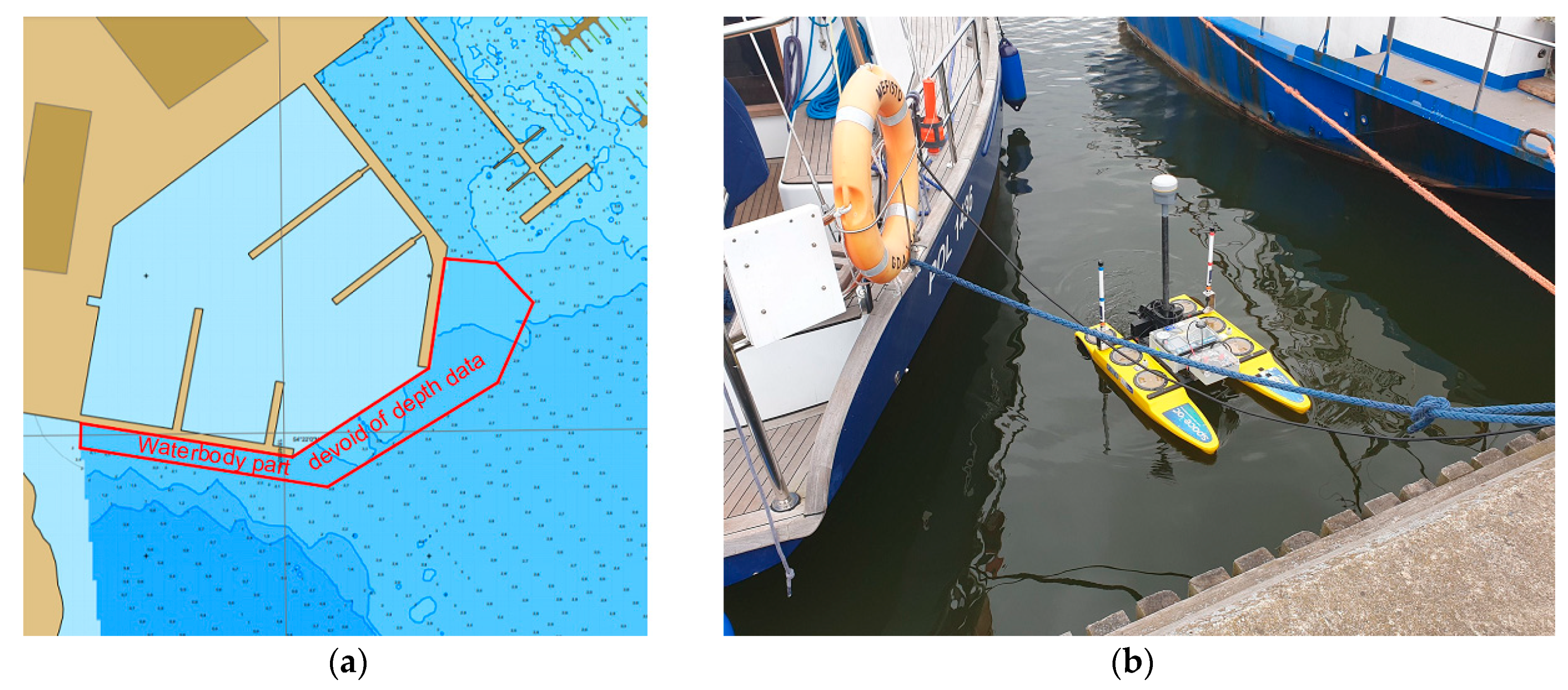
2.4.1. Hydrographic Surveys Using an USV

The surveys used a USV that operated in two modes—automatic and manual [39]. Despite the possibility of carrying out surveys in an automatic mode, the bathymetric measurements of harbor basins were conducted mainly using the direct manual mode (Figure 6).
Bathymetric measurements of the approach fairway were conducted in the automatic mode using an unmanned vessel. The sounding profiles were designed using the Trimble Business Center (TBC) software at the distances of every 10 m (based on the requirements of the IHO S-44 standard), taking account of the shoal adjacent to the Green Islands area (Figure 7).
The performance of bathymetric measurements by the USV requires direct supervision provided by the Navigator One AMG vessel. The main problem associated with the performance of bathymetric soundings in automatic mode is the need to ensure that the waterbody is so well covered with measurements that there are no places where surveys were not conducted. Despite much effort, it was not possible to predict if vessels were present or not in particular berths. The lack of possibility for carrying out measurements in specific locations due to the yachts moored there, resulted in the emergence of a waterbody part devoid of data on depths (Figure 8a). It was, therefore, decided that in the places where yachts moor, it was possible to carry out surveys using an USV by controlling it manually (directly), which involved the unmanned vessel entering between the yachts (Figure 8b). The small size of the USV demonstrated that such maneuvres were fully secure and posed no hazard of collision or damage to the moored yachts.
Bathymetric measurements with the use of the USV lasted 3 h 15 min, during which 11,687 points were recorded at a frequency of 1 Hz. At this time, the USV traveled 4.743 km with an average speed of 1.46 km/h.

2.4.2. Supplementary Bathymetric and Geodetic Measurements

Near the NSC-GUPES, there is an extensive shoal with depths of less than 1 m. This is indicated by five buoys—one red and four yellow. Thanks to these buoys (Figure 9), safe water was marked out for yachts going to the NSC and Central Center for Academic Sport AZS Górki Zachodnie harbor from the south (the Vistula River mouth). It should be noted that eight informal “navigation marks”, i.e., weighted empty water tanks attached to the seafloor, are found in that waterbody. It can be stated with a high degree of probability that the above-mentioned “unofficial safe water marks” were placed there in order to fully indicate the Green Islands shallow area for sailors and other vessels. In terms of the navigation safety, the “informal marks” found there were fully justified, since several dozen or more small-sized sailing vessels often train within that area, and the shoal poses a real navigational hazard to them.
Since the above-mentioned marks actually exist but were not shown on official navigational charts, a need appeared for its inventory, which was carried out using a Navigator One AMG vessel, while the surveys were conducted using a Trimble R10 GNSS receiver. The coordinates of particular marks, both formal and less formal ones, are presented in Table 1.
The coordinates of the navigation marks buoys are provided (Table 1) in two systems—the Cartesian coordinate system 2000, which is applicable in Poland and the geodetic coordinates in the World Geodetic System 1984 (WGS 84), which is commonly used in navigation.

3. Results

The measurement results obtained from the USV enabled the development of a Digital Sea Bottom Model (DSBM) [40,41]. In order to determine the isoline course, the Inverse Distance Weighting (IDW) interpolation, with a separation every 0.5 m, was applied. The size of the grid cell was set at 0.5 × 0.5 m. In this way, a matrix of 689 × 781 cells covering the NSC-GUPES area and the adjacent waterbodies was created. DSBM are also used for its spatial presentation. The depths were plotted with a resolution of 0.1 m, in accordance with [42] for a shallow waterbody, with depths of up to 31 m. The study was carried out in the ArcGIS environment, using the Electronic Navigational Chart (ENC) PL5GDNA cell.
The scales of cartographic images for such waterbodies are usually between 1:500 and 1:1000. For measurements carried out in accordance with [43,44], the map scales were as follows: 1:100, 1:500, or 1:1000. The scale was adjusted to the printout format, in order to maintain the cartometric properties. The box contained the coordinates in which the development was prepared. Navigational charts were developed in the Universal Transverse Mercator (UTM) system, on the WGS 84 ellipsoid [45]. Moreover, it was decided that apart from the maps, two bathymetric charts would be additionally developed, with the purpose of managing the navigation safety in both the yacht port and its approach fairway. These were developed in the National (Polish) Cartesian coordinate system 2000 [46]. It was created by the application of the Gauss-Krüger projection [47] for the Geodetic Reference System 80 (GRS 80) ellipsoid, in four three-stage zones with central meridians of 15 °E, 18 °E, 21 °E, and 24 °E. On the other hand, the measured depths were referred to the chart datum, which in the case of Poland was 508 cm for the PL-KRON86-NH height system.
The conducted hydrographic surveys and the accompanying geodetic inventory of the quays enabled the development of a navigational chart of the yacht port, which was Poland’s first hydrographic cartographic image developed entirely by an unmanned vessel. Hydrographic surveys resulted in the development of the following navigational charts:
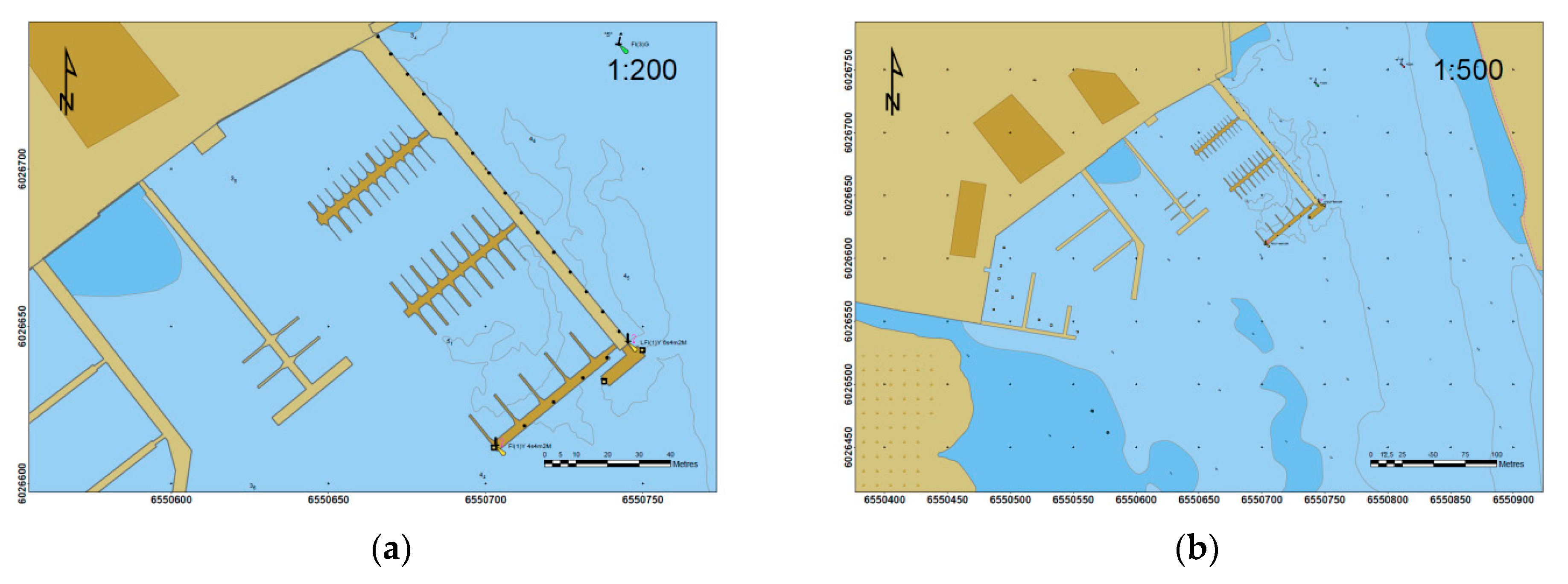
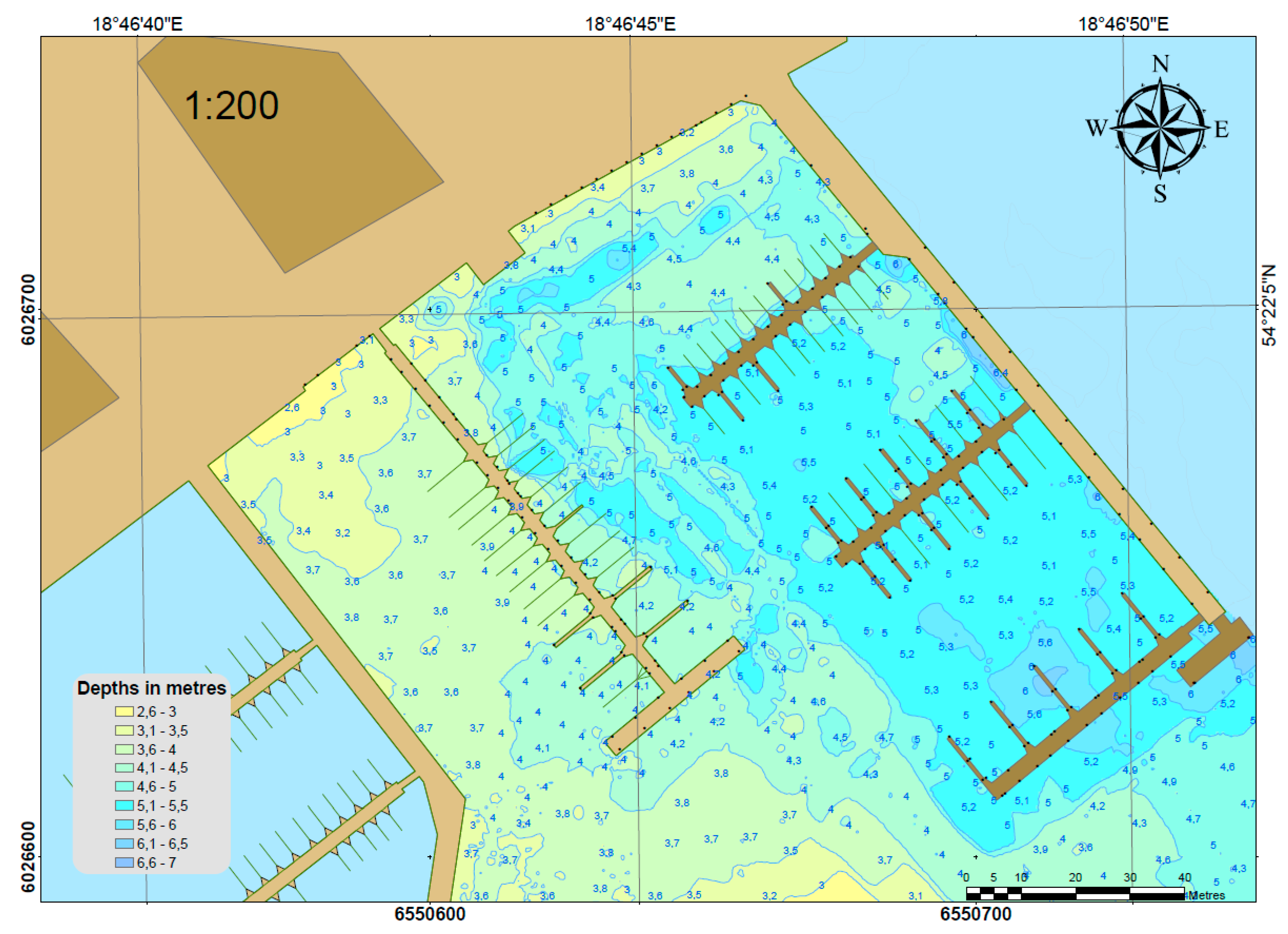
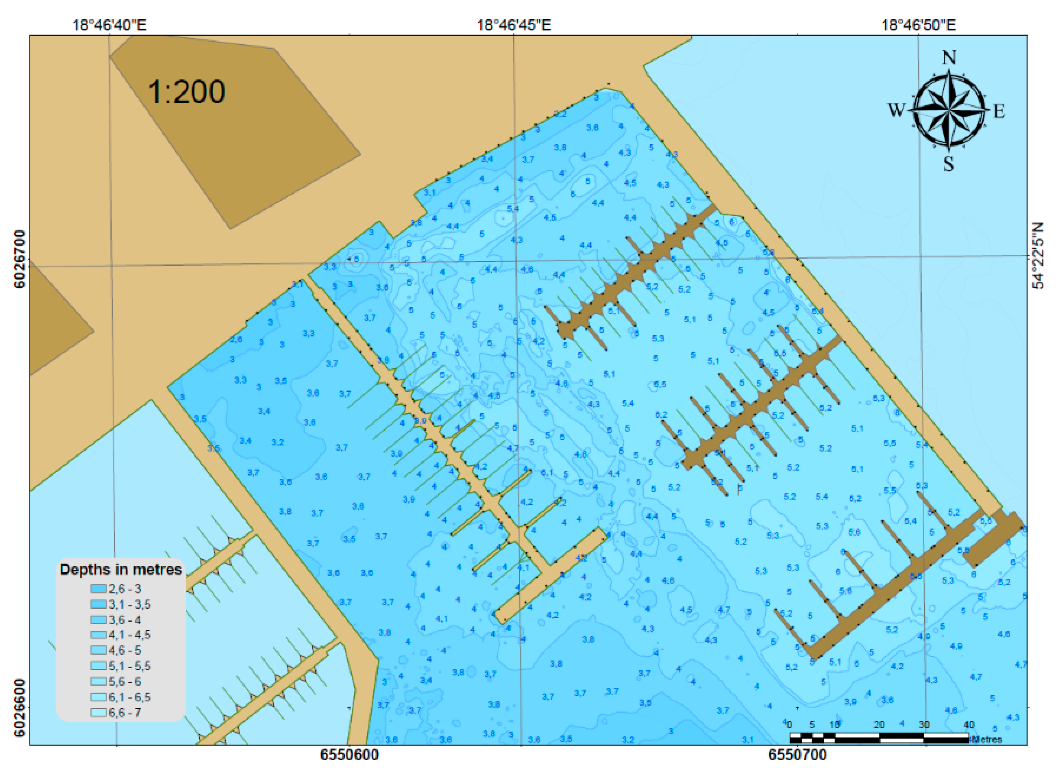
  • A navigational chart of the yacht port developed in the UTM system, at a scale of 1:200, with an isobath spacing of 0.5 m and depth data density of 10 m2. Its intended purpose was to provide information, which arose from the need to inform entering vessels about the current water level in the marina (Figure 10).
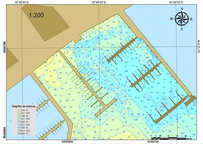
  • A bathymetric chart, i.e., a map of the yacht port with a scale of 1:200, devoid of isobaths with a depth data density of 2 m2. Thanks to bathymetric data, including depths at particular berths, this was intended for the management of berths in the harbor. This would allow the harbor master to assign berths to the yachts entering the harbor, on the basis of their draft. Moreover, it enabled the management of navigability in the yacht port, which is associated with the need to maintain specified depths at the marina (Figure 11).
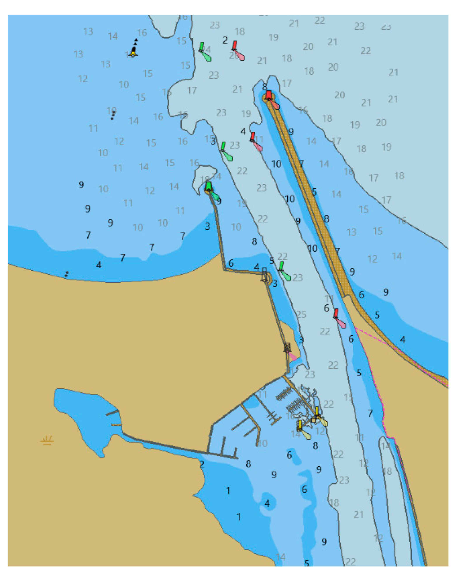
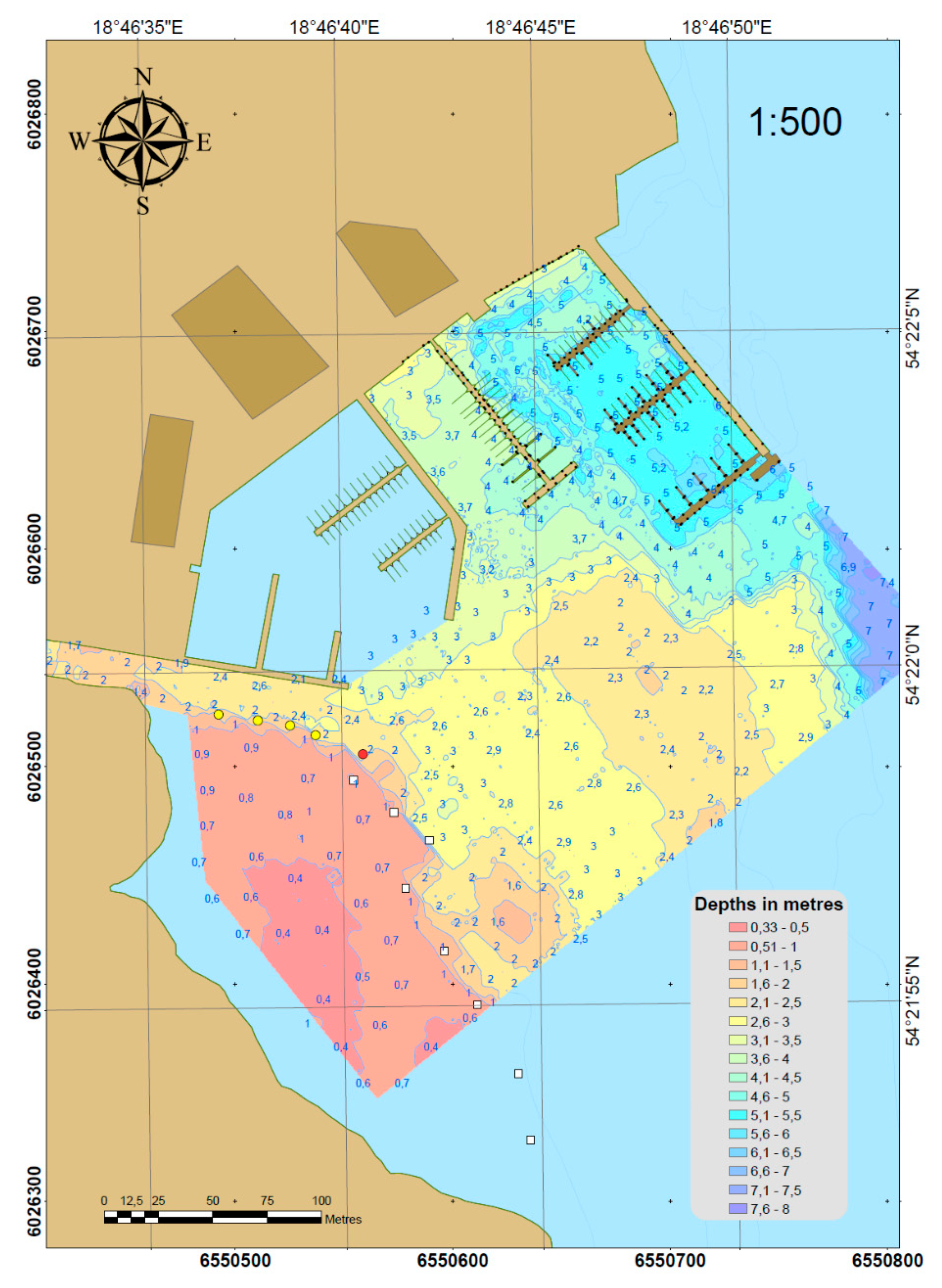
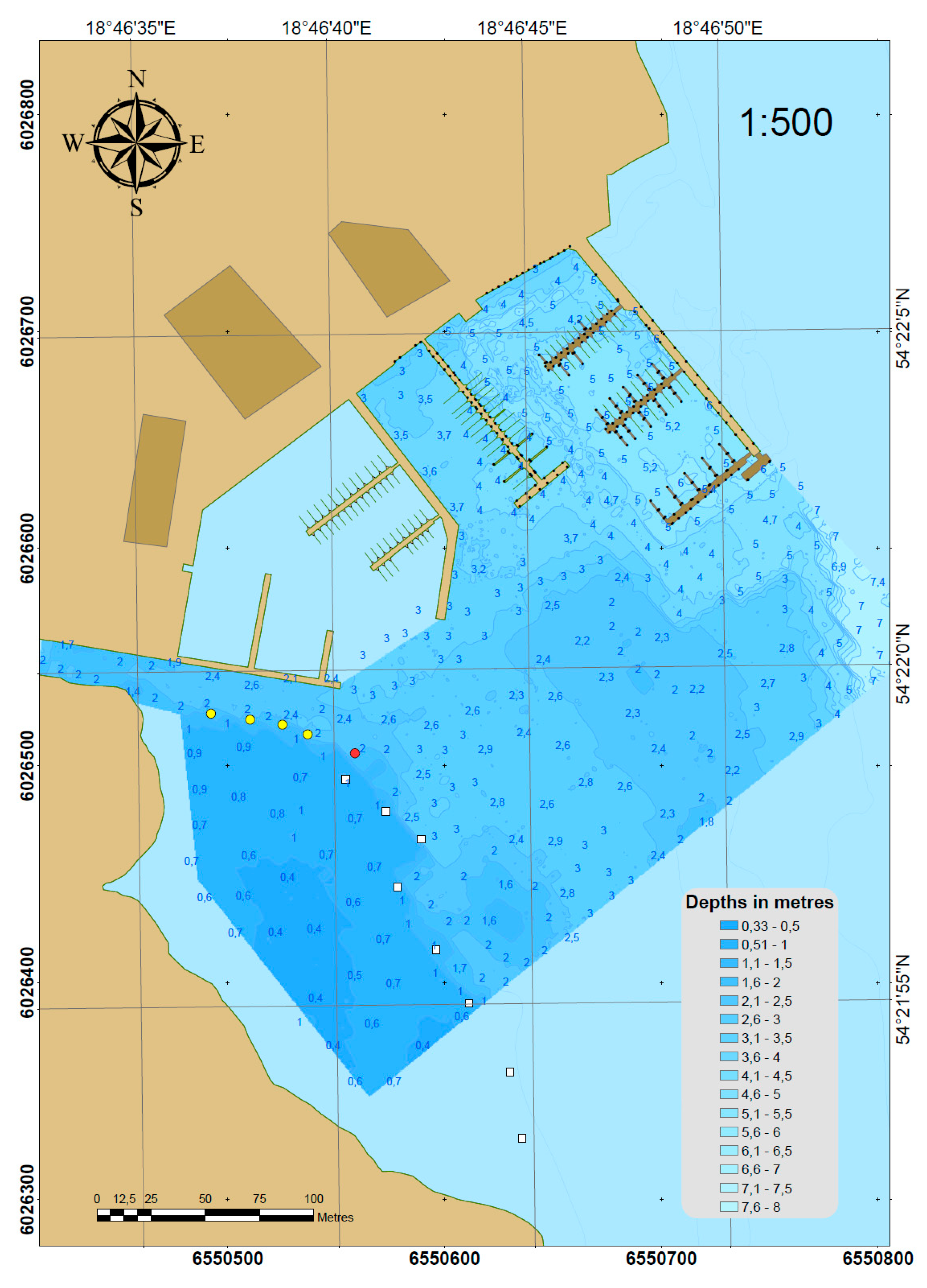
  • A navigational chart of the yacht port approach fairway, including the waterbody of the Green Islands shoal, developed in the UTM system at a scale of 1:500, with an isobath spacing of 0.5 m and depth data density of 10 m2. This was designed to ensure the navigation safety on the approach fairway (Figure 12).
  • A bathymetric chart, i.e., a map of the approach fairway with a scale of 1:500, devoid of isobaths with a depth data density of 2 m2. Thanks to bathymetric data, including depths at particular berths, this was intended for the management of navigability in the marina approach fairway and of the navigation marking systems in the area surrounding the yacht port (Figure 13).
In order to assess the reliability of the developed new maps and bathymetric charts, these needed to be compared to the current maps of this area originating from the ENC cell. Figure 14 shows a chart of the yacht port and its approach fairway originating from the ENC cell.
From the comparative analysis of the navigational chart of the NSC-GUPES yacht port developed by the USV and from the ENC map, it followed that the ENC chart failed to reflect the significant variability at a depth of 3–5 m, within the northern part of the main basin. The ENC map provided a constant depth of 3.5 m. Moreover, in the western basin of the NSC-GUPES yacht port, the ENC chart did not provide a single depth value while only indicating a shoal found in the northern part. The lack of any depth value in the western basin of the NSC should not occur.
Having assessed the reliability of the new navigational chart of the NSC-GUPES approach fairway and the ENC map, it should be noted that the ENC chart contained no safe water marks restricting the Green Islands shoal, which were significant from the navigation safety perspective. The red and four yellow buoys were signs that enabled safe entry into the internal bay of the reservation along the southern quay of the Central Center for Academic Sport AZS Górki Zachodnie. Moreover, it could be concluded that the informal signs, i.e., the water tanks, were properly situated on the isobath of 1 m, hence, its usefulness for sailing in this area was high.

4. Discussion

Seabed surveys in the port areas were carried out in various ways. Currently, the most frequently used measurement methods include surveys using bathymetric and terrestrial LiDAR mounted on a manned aircraft [48,49], analysis of high-resolution multispectral imagery from satellites such as IKONOS, QuickBird, and WorldView [50,51], or moderate-resolution multispectral images from Landsat, and Sentinel satellites [52,53,54] or bathymetric measurements realized with the use of manned hydrographic vessels equipped with hydroacoustic devices [55]. It should be emphasized that in the available literature, it is impossible to find USV (except for one publication [2]) that would perform such surveys as in the presented article. According to the authors, this was the optimal in relation to other measurement methods.
For example, the applied solution was much less expensive than the bathymetric LiDAR and it did not require performing photogrammetric measurements using a manned aircraft. In addition, the depth accuracy was from varied in centimeter-dozens for a bathymetric LiDAR and it depended on the diffuse attenuation coefficient that was used to characterize the penetration of light into natural waters. Therefore, there is no 100% guarantee that the recommended accuracy of the depth measurement is in accordance with the requirements set out for the most stringent IHO order-special [horizontal position error ≤2 m (p = 0.95), vertical position error ≤0.25 m (p = 0.95)], according to which bathymetric surveys should be carried out in the coastal zone [56,57].
The method for determining the bathymetry of waterbodies using high-resolution satellite images have a limited range of operation. It can be applied only on medium depths, with appropriate water transparency [58]. Moreover, as shown by the results of other studies [59,60], the accuracy of depth measurements using this method was unsatisfactory and amounted to 1–2 m (p = 0.95), therefore, it might not meet the requirements provided for the IHO special order [7].
Contrary to manned hydrographic vessels, bathymetric measurements with the use of USVs can be carried out in hard-to-reach places, as shown in Figure 8b. As a result, the developed bathymetric and navigational charts reliably reflect the seafloor relief. Additionally, the method for performing bathymetric measurements using manned hydrographic vessels is much safer than with the use of USVs, because it might cause damage to measurement equipment [61], port infrastructure, and ships.
The unique aspect of this publication is the definition and development of navigational and bathymetric charts that can be applied in port areas for various needs. The maps shown in Figure 10 and Figure 12 can be used to provide information regarding depths in the marina. This information can apply for the daily management of a marina, as well as for planning its development. On the other hand, the charts presented in Figure 11 and Figure 13 are used by the boatswain’s office to manage the berths in a yacht port. Information about the depths in particular mooring places, allows for their optimal and safe selection for the yacht entering the marina, with specific dimensions and draft.

5. Conclusions

The article presents the methodology for the use of an USV of the X class, which was applied to carry out bathymetric measurements of the yacht port and its approach fairway. The small size of the vessel demonstrated the possibility of carrying out a depth measurement within the harbor and for entering each berth of the harbor (y-booms). Moreover, where vessels were present at the berth, the USV could also carry out the survey by entering between the moored yachts, thanks to the direct (manual) control.
The unmanned vessel fully proved its worth in the measurements of the extensive approach fairway area and the nearby Green Islands shoal. Despite waving, the surveys in the automatic mode were conducted smoothly.
As a result, four cartographic images were developed—two navigational charts (of the yacht port and its approach fairway) intended to ensure navigation safety, and two bathymetric charts with an increased accuracy, which could be used in managing the navigability of the harbor and the adjacent waterbody, and for designing the navigation marks of the waterbody.
The conducted hydrographic surveys and the accompanying geodetic inventory of the quays enabled the development of a navigational chart of the yacht port, which is Poland’s first hydrographic cartographic image developed entirely by an unmanned vessel.
Based on the research conducted, it appears that a particular advantage of USVs, as compared to classical manned vehicles, is their ability to enter a hard-to-reach waterbody [15]. Moreover, USVs are increasingly used for tasks related to supporting the navigation process [62], in underwater photogrammetry [63], or in geological [1] and hydrographic surveys [64].

Author Contributions

Conceptualization, C.S. and H.L.; Data curation, A.M. and P.D.; Investigation, M.S. (Mariusz Specht), A.M., P.D., and P.C.; Methodology, M.S. (Maciej Szafran), and H.L.; Supervision, C.S. and M.S. (Mariusz Specht); Visualization, A.M. and P.C.; Writing—original draft, C.S. and M.S. (Mariusz Specht); Writing—review & editing, M.S. (Maciej Szafran) and P.D. All authors have read and agreed to the published version of the manuscript.

Funding

This research received no external funding.

Conflicts of Interest

The authors declare no conflict of interest.

References

  1. Giordano, F.; Mattei, G.; Parente, C.; Peluso, F.; Santamaria, R. Integrating Sensors into a Marine Drone for Bathymetric 3D Surveys in Shallow Waters. Sensors 2016, 16, 41. [Google Scholar] [CrossRef] [Green Version]
  2. Mattei, G.; Troisi, S.; Aucelli, P.P.C.; Pappone, G.; Peluso, F.; Stefanile, M. Sensing the Submerged Landscape of Nisida Roman Harbour in the Gulf of Naples from Integrated Measurements on a USV. Water 2018, 10, 1686. [Google Scholar] [CrossRef] [Green Version]
  3. International Hydrographic Organization. Manual on Hydrography, 1st ed.; Publication C-13; IHO: Monte Carlo, Monaco, 2005.
  4. National Oceanic and Atmospheric Administration. NOS Hydrographic Surveys Specifications and Deliverables; NOAA: Silver Spring, MD, USA, 2017.
  5. United States Army Corps of Engineers. EM 1110-2-1003 USACE Standards for Hydrographic Surveys; USACE: Washington, DC, USA, 2013. [Google Scholar]
  6. Canadian Hydrographic Service. CHS Standards for Hydrographic Surveys, 2nd ed.; CHS: Ottawa, ON, Canada, 2013. [Google Scholar]
  7. International Hydrographic Organization. IHO Standards for Hydrographic Surveys, 5th ed.; Special Publication No. 44; IHO: Monte Carlo, Monaco, 2008.
  8. Specht, C.; Świtalski, E.; Specht, M. Application of an Autonomous/Unmanned Survey Vessel (ASV/USV) in Bathymetric Measurements. Pol. Marit. Res. 2017, 24, 36–44. [Google Scholar] [CrossRef] [Green Version]
  9. Stateczny, A.; Grońska, D.; Motyl, W. Hydrodron—New Step for Professional Hydrography for Restricted Waters. In Proceedings of the 2018 Baltic Geodetic Congress, Olsztyn, Poland, 21–23 June 2018. [Google Scholar]
  10. Breivik, M. Topics in Guided Motion Control of Marine Vehicles. Ph.D. Thesis, Norwegian University of Science and Technology, Trondheim, Norway, June 2010. [Google Scholar]
  11. Wróbel, K.; Montewka, J.; Kujala, P. System-theoretic Approach to Safety of Remotely-controlled Merchant Vessel. Ocean Eng. 2018, 152, 334–335. [Google Scholar] [CrossRef]
  12. Kurowski, M.; Thal, J.; Damerius, R.; Korte, H.; Jeinsch, T. Automated Survey in Very Shallow Water Using an Unmanned Surface Vehicle. IFAC Pap. 2019, 52, 146–151. [Google Scholar] [CrossRef]
  13. Stateczny, A.; Kazimierski, W.; Burdziakowski, P.; Motyl, W.; Wisniewska, M. Shore Construction Detection by Automotive Radar for the Needs of Autonomous Surface Vehicle Navigation. ISPRS Int. J. Geo Inf. 2019, 8, 80. [Google Scholar] [CrossRef] [Green Version]
  14. Li, C.; Jiang, J.; Duan, F.; Liu, W.; Wang, X.; Bu, L.; Sun, Z.; Yang, G. Modeling and Experimental Testing of an Unmanned Surface Vehicle with Rudderless Double Thrusters. Sensors 2019, 19, 2051. [Google Scholar] [CrossRef] [PubMed] [Green Version]
  15. Romano, A.; Duranti, P. Autonomous Unmanned Surface Vessels for Hydrographic Measurement and Environmental Monitoring. In Proceedings of the FIG Working Week 2012, Rome, Italy, 6–10 May 2012. [Google Scholar]
  16. Stateczny, A.; Włodarczyk-Sielicka, M.; Grońska, D.; Motyl, W. Multibeam Echosounder and LiDAR in Process of 360-degree Numerical Map Production for Restricted Waters with HydroDron. In Proceedings of the 2018 Baltic Geodetic Congress, Olsztyn, Poland, 21–23 June 2018. [Google Scholar]
  17. Stateczny, A.; Burdziakowski, P.; Najdecka, K.; Domagalska-Stateczna, B. Accuracy of Trajectory Tracking Based on Nonlinear Guidance Logic for Hydrographic Unmanned Surface Vessels. Sensors 2020, 20, 832. [Google Scholar] [CrossRef] [PubMed] [Green Version]
  18. Mu, D.; Wang, G.; Fan, Y.; Qiu, B.; Sun, X. Adaptive Trajectory Tracking Control for Underactuated Unmanned Surface Vehicle Subject to Unknown Dynamics and Time-varing Disturbances. Appl. Sci. 2018, 8, 547. [Google Scholar] [CrossRef] [Green Version]
  19. Naus, K.; Marchel, Ł.; Szymak, P.; Nowak, A. Assessment of the Accuracy of Determining the Angular Position of the Unmanned Bathymetric Surveying Vehicle Based on the Sea Horizon Image. Sensors 2019, 19, 4644. [Google Scholar] [CrossRef] [PubMed] [Green Version]
  20. Yang, Y.; Li, Q.; Zhang, J.; Xie, Y. Iterative Learning-based Path and Speed Profile Optimization for an Unmanned Surface Vehicle. Sensors 2020, 20, 439. [Google Scholar] [CrossRef] [PubMed] [Green Version]
  21. Nikolakopoulos, K.G.; Lampropoulou, P.; Fakiris, E.; Sardelianos, D.; Papatheodorou, G. Synergistic Use of UAV and USV Data and Petrographic Analyses for the Investigation of Beachrock Formations: A Case Study from Syros Island, Aegean Sea, Greece. Minerals 2018, 8, 534. [Google Scholar] [CrossRef] [Green Version]
  22. Zwolak, K.; Wigley, R.; Bohan, A.; Zarayskaya, Y.; Bazhenova, E.; Dorshow, W.; Sumiyoshi, M.; Sattiabaruth, S.; Roperez, J.; Proctor, A.; et al. The Autonomous Underwater Vehicle Integrated with the Unmanned Surface Vessel Mapping the Southern Ionian Sea. The Winning Technology Solution of the Shell Ocean Discovery XPRIZE. Remote Sens. 2020, 12, 1344. [Google Scholar] [CrossRef] [Green Version]
  23. Liu, Z.; Zhang, Y.; Yu, X.; Yuan, C. Unmanned Surface Vehicles: An Overview of Developments and Challenges. Annu. Rev. Control. 2016, 41, 71–93. [Google Scholar] [CrossRef]
  24. RAND. U.S. Navy Employment Options for UNMANNED SURFACE VEHICLES (USVs). Available online: https://www.rand.org/content/dam/rand/pubs/research_reports/RR300/RR384/RAND_RR384.pdf (accessed on 1 August 2020).
  25. Specht, M. Method of Evaluating the Positioning System Capability for Complying with the Minimum Accuracy Requirements for the International Hydrographic Organization Orders. Sensors 2019, 19, 3860. [Google Scholar] [CrossRef] [Green Version]
  26. Pasławski, J. Introduction to Cartography and Topography; Nowa Era Publishing House: Wrocław, Poland, 2006. (In Polish) [Google Scholar]
  27. United States Department of the Navy. The Navy Unmanned Surface Vehicle (USV) Master Plan. Available online: https://www.navy.mil/navydata/technology/usvmppr.pdf (accessed on 1 August 2020).
  28. Specht, M.; Specht, C.; Lasota, H.; Cywiński, P. Assessment of the Steering Precision of a Hydrographic Unmanned Surface Vessel (USV) along Sounding Profiles Using a Low-cost Multi-Global Navigation Satellite System (GNSS) Receiver Supported Autopilot. Sensors 2019, 19, 3939. [Google Scholar] [CrossRef] [Green Version]
  29. Makar, A. Dynamic Tests of ASG-EUPOS Receiver in Hydrographic Application. In Proceedings of the 18th International Multidisciplinary Scientific GeoConference SGEM 2018, Albena, Bulgaria, 2–8 July 2018. [Google Scholar]
  30. Grządziel, A. Results from Developments in the Use of a Scanning Sonar to Support Diving Operations from a Rescue Ship. Remote Sens. 2020, 12, 693. [Google Scholar] [CrossRef] [Green Version]
  31. Grządziel, A. Using Remote Sensing Data to Identify Large Bottom Objects: The Case of World War II Shipwreck of General von Steuben. Geosciences 2020, 10, 240. [Google Scholar] [CrossRef]
  32. Council of Ministers of the Republic of Poland. Ordinance of the Council of Ministers of 15 October 2012 on the National Spatial Reference System; Council of Ministers of the Republic of Poland: Warsaw, Poland, 2012. (In Polish)
  33. Specht, C.; Lewicka, O.; Specht, M.; Dąbrowski, P.; Burdziakowski, P. Methodology for Carrying out Measurements of the Tombolo Geomorphic Landform Using Unmanned Aerial and Surface Vehicles near Sopot Pier, Poland. J. Mar. Sci. Eng. 2020, 8, 384. [Google Scholar] [CrossRef]
  34. Specht, M.; Specht, C.; Wąż, M.; Naus, K.; Grządziel, A.; Iwen, D. Methodology for Performing Territorial Sea Baseline Measurements in Selected Waterbodies of Poland. Appl. Sci. 2019, 9, 3053. [Google Scholar] [CrossRef] [Green Version]
  35. Specht, C.; Pawelski, J.; Smolarek, L.; Specht, M.; Dabrowski, P. Assessment of the Positioning Accuracy of DGPS and EGNOS Systems in the Bay of Gdansk Using Maritime Dynamic Measurements. J. Navig. 2019, 72, 5755–5787. [Google Scholar] [CrossRef] [Green Version]
  36. Baptista, P.; Bastos, L.; Bernardes, C.; Cunha, T.; Dias, J. Monitoring Sandy Shores Morphologies by DGPS—A Practical Tool to Generate Digital Elevation Models. J. Coast. Res. 2008, 24, 15161–15528. [Google Scholar] [CrossRef]
  37. Krueger, C.P.; de Souza, A.V. The Geodesy in the Hydography. Rev. Bras. Cartogr. 2014, 66, 1485–1493. [Google Scholar]
  38. Makar, A. Determination of Inland Areas Coastlines. In Proceedings of the 18th International Multidisciplinary Scientific GeoConference SGEM 2018, Albena, Bulgaria, 2–8 July 2018. [Google Scholar]
  39. Specht, C.; Specht, M.; Cywiński, P.; Skóra, M.; Marchel, Ł.; Szychowski, P. A New Method for Determining the Territorial Sea Baseline Using an Unmanned, Hydrographic Surface Vessel. J. Coast. Res. 2019, 35, 925–936. [Google Scholar] [CrossRef]
  40. Makar, A. The Sea Bottom Surface Described by Coons Pieces. Sci. J. Marit. Univ. Szczec. 2016, 45, 187–190. [Google Scholar]
  41. Sassais, R.; Makar, A. Methods to Generate Numerical Models of Terrain for Spatial ENC Presentation. Annu. Navig. 2011, 18, 69–81. [Google Scholar]
  42. International Hydrographic Organization. Regulations of the IHO for International (INT) Charts and Chart Specifications of the IHO, 4.8.0th ed.; IHO: Monte Carlo, Monaco, 2018.
  43. Minister of Maritime Economy. Ordinance of the Minister of Maritime Economy of 23 October 2006 on the Technical Conditions for the Use of Marine Hydrotechnical Structures and the Detailed Scope of Inspections; Minister of Maritime Economy: Warsaw, Poland, 2006. (In Polish)
  44. Minister of Transport and Maritime Economy. Ordinance of the Minister of Transport and Maritime Economy of 1 June 1998 on the Technical Conditions to Be Met by Marine Hydrotechnical Structures and Their Location; Minister of Transport and Maritime Economy: Warsaw, Poland, 1998. (In Polish)
  45. National Imagery and Mapping Agency. Department of Defense World Geodetic System 1984, its Definition and Relationships with Local Geodetic Systems, 3rd ed.; NIMA Technical Report TR8350.2; NIMA: Springfield, VA, USA, 2004. [Google Scholar]
  46. Kadaj, R.J. Polish Coordinate Systems. Transformation Formulas, Algorithms and Softwares. Available online: http://www.geonet.net.pl/images/2002_12_uklady_wspolrz.pdf (accessed on 1 August 2020). (In Polish).
  47. Deakin, R.E.; Hunter, M.N.; Karney, C.F.F. The Gauss-Krüger Projection. In Proceedings of the 23rd Victorian Regional Survey Conference, Warrnambool, Australia, 10–12 September 2010. [Google Scholar]
  48. Vrbancich, J.; Hallett, M.; Hodges, G. Airborne Electromagnetic Bathymetry of Sydney Harbour. Explor. Geophys. 2000, 31, 179–186. [Google Scholar] [CrossRef]
  49. Wilson, K.M.; Power, H.E. Seamless Bathymetry and Topography Datasets for New South Wales, Australia. Sci. Data 2018, 5, 180115. [Google Scholar] [CrossRef] [Green Version]
  50. Erena, M.; Domínguez, J.A.; Atenza, J.F.; García-Galiano, S.; Soria, J.; Pérez-Ruzafa, Á. Bathymetry Time Series Using High Spatial Resolution Satellite Images. Water 2020, 12, 531. [Google Scholar] [CrossRef] [Green Version]
  51. Specht, M.; Specht, C.; Lewicka, O.; Makar, A.; Burdziakowski, P.; Dąbrowski, P. Study on the Coastline Evolution in Sopot (2008–2018) Based on Landsat Satellite Imagery. J. Mar. Sci. Eng. 2020, 8, 464. [Google Scholar] [CrossRef]
  52. Gabr, B.; Ahmed, M.; Marmoush, Y. PlanetScope and Landsat 8 Imageries for Bathymetry Mapping. J. Mar. Sci. Eng. 2020, 8, 143. [Google Scholar] [CrossRef] [Green Version]
  53. Kimeli, A.; Thoya, P.; Ngisiang’e, N.; Ong’anda, H.; Magori, C. Satellite-derived Bathymetry: A Case Study of Mombasa Port Channel and its Approaches, Kenya. West. Indian Ocean. J. Mar. Sci. 2018, 17, 93–102. [Google Scholar] [CrossRef]
  54. Mateo-Pérez, V.; Corral-Bobadilla, M.; Ortega-Fernández, F.; Vergara-González, E.P. Port Bathymetry Mapping Using Support Vector Machine Technique and Sentinel-2 Satellite Imagery. Remote Sens. 2020, 12, 2069. [Google Scholar] [CrossRef]
  55. Specht, M.; Specht, C.; Mindykowski, J.; Dąbrowski, P.; Maśnicki, R.; Makar, A. Geospatial Modeling of the Tombolo Phenomenon in Sopot Using Integrated Geodetic and Hydrographic Measurement Methods. Remote Sens. 2020, 12, 737. [Google Scholar] [CrossRef] [Green Version]
  56. Doron, M.; Babin, M.; Mangin, A.; Hembise, O. Estimation of Light Penetration, and Horizontal and Vertical Visibility in Oceanic and Coastal Waters from Surface Reflectance. J. Geophys. Res. 2007, 112, C06003. [Google Scholar] [CrossRef] [Green Version]
  57. Stramska, M.; Świrgoń, M. Influence of Atmospheric Forcing and Freshwater Discharge on Interannual Variability of the Vertical Diffuse Attenuation Coefficient at 490 nm in the Baltic Sea. Remote Sens. Environ. 2014, 140, 155–164. [Google Scholar] [CrossRef]
  58. Kasvi, A.; Salmela, J.; Lotsari, E.; Kumpula, T.; Lane, S.N. Comparison of Remote Sensing Based Approaches for Mapping Bathymetry of Shallow, Clear Water Rivers. Geomorphology 2019, 33, 180–197. [Google Scholar] [CrossRef]
  59. Li, J.; Knapp, D.E.; Schill, S.R.; Roelfsema, C.; Phinn, S.; Silman, M.; Mascaro, J.; Asner, G.P. Adaptive Bathymetry Estimation for Shallow Coastal Waters Using Planet Dove Satellites. Remote Sens. Environ. 2019, 232, 111302. [Google Scholar] [CrossRef]
  60. Yunus, A.P.; Dou, J.; Song, X.; Avtar, R. Improved Bathymetric Mapping of Coastal and Lake Environments Using Sentinel-2 and Landsat-8 Images. Sensors 2019, 19, 2788. [Google Scholar] [CrossRef] [Green Version]
  61. Specht, C.; Weintrit, A.; Specht, M. Determination of the Territorial Sea Baseline—Aspect of Using Unmanned Hydrographic Vessels. TransNav Int. J. Mar. Navig. Saf. Sea Transp. 2016, 10, 649–654. [Google Scholar] [CrossRef] [Green Version]
  62. Naus, K.; Marchel, Ł. Use of a Weighted ICP Algorithm to Precisely Determine USV Movement Parameters. Appl. Sci. 2019, 9, 3530. [Google Scholar] [CrossRef] [Green Version]
  63. Giordano, F.; Mattei, G.; Parente, C.; Peluso, F.; Santamaria, R. MicroVEGA (Micro Vessel for Geodetics Application): A Marine Drone for the Acquisition of Bathymetric Data for GIS Applications. Int. Arch. Photogramm. Remote Sens. Spat. Inf. Sci. 2015, XL-5/W5, 123–130. [Google Scholar] [CrossRef] [Green Version]
  64. Rowley, J. Autonomous Unmanned Surface Vehicles (USV): A Paradigm Shift for Harbor Security and Underwater Bathymetric Imaging. In Proceedings of the OCEANS 2018 MTS/IEEE Charleston, Charleston, SC, USA, 22–25 October 2018. [Google Scholar]
Figure 1. Hydrographic unmanned surface vessels. A multi-purpose XOCEAN XO-450 vessel (a), a double-hulled HydroDron (b), and a Seafloor Systems vessel (c).
Remotesensing 12 02585 g001
Figure 2. Unmanned Surface Vehicle (USV), before (a) and after (b) the modernization.
Remotesensing 12 02585 g002
Figure 3. The hydrographic survey motorboat Navigator One AMG (a), an unmanned vessel during hydrographic surveys in automatic mode, the team supervising the operation of the Unmanned Surface Vehicle (USV) from the deck of the Navigator One AMG vessel (b).
Remotesensing 12 02585 g003
Figure 4. The location of the National Sailing Centre at the Gdańsk University of Physical Education and Sport (NSC-GUPES).
Remotesensing 12 02585 g004
Figure 5. Navigation marks and depths on the approach fairway to the National Sailing Centre at the Gdańsk University of Physical Education and Sport (NSC-GUPES).
Remotesensing 12 02585 g005
Figure 6. Unmanned Surface Vehicle (USV) surveys in the yacht port during the direct control (a), and the trajectory of bathymetric measurements in the harbor (b).
Remotesensing 12 02585 g006
Figure 7. Designed sounding profiles in the waterbody adjacent to the National Sailing Centre at the Gdańsk University of Physical Education and Sport (NSC-GUPES).
Remotesensing 12 02585 g007
Figure 8. The waterbody in which no surveys were conducted in an automatic mode, due to the yachts moored there (a). A depth measurement between the moored yachts—direct control (b).
Remotesensing 12 02585 g008
Figure 9. Navigation marks on the shoal in the vicinity of Green Islands.
Remotesensing 12 02585 g009
Figure 10. Navigational chart of the National Sailing Centre at the Gdańsk University of Physical Education and Sport (NSC-GUPES).
Remotesensing 12 02585 g010
Figure 11. Bathymetric chart of the National Sailing Centre at the Gdańsk University of Physical Education and Sport (NSC-GUPES).
Remotesensing 12 02585 g011
Figure 12. Navigational chart of the approach fairway to the National Sailing Centre at the Gdańsk University of Physical Education and Sport (NSC-GUPES).
Remotesensing 12 02585 g012
Figure 13. Bathymetric chart of the approach fairway to the National Sailing Centre at the Gdańsk University of Physical Education and Sport (NSC-GUPES).
Remotesensing 12 02585 g013
Figure 14. Navigational charts of the yacht port (a) and approach fairway (b) of the National Sailing Centre at the Gdańsk University of Physical Education and Sport (NSC-GUPES), originating from the official Electronic Navigational Chart (ENC) cells.
Remotesensing 12 02585 g014
Table 1. The coordinates of the navigation marks indicating the Green Islands shoal, on the approach fairway to the yacht port complex of the National Sailing Centre (NSC) and Central Center for Academic Sport AZS Górki Zachodnie from the south.
IDNameX(PL-2000)Y(PL-2000)ϕ(WGS-84)λ(WGS-84)
1Water tank No.16026328.223 m6550635.838 mN 54°21’52.99331”E 18°46’44.63700”
2Water tank No. 26026358.779 m6550630.249 mN 54°21’53.98352”E 18°46’44.34616”
3Water tank No. 36026390.466 m6550611.273 mN 54°21’55.01510”E 18°46’43.31460”
4Water tank No. 46026415.014 m6550596.046 mN 54°21’55.81443”E 18°46’42.48627”
5Water tank No. 56026443.936 m6550578.245 mN 54°21’56.75618”E 18°46’41.51810”
6Water tank No. 66026466.097 m6550589.201 mN 54°21’57.46896”E 18°46’42.13844”
7Water tank No. 76026478.828 m6550572.951 mN 54°21’57.88651”E 18°46’41.24620”
8Water tank No. 86026493.689 m6550554.416 mN 54°21’58.37373”E 18°46’40.22876”
9Red buoy No. 16026505.642 m6550558.684 mN 54°21’58.75878”E 18°46’40.47243”
10Yellow buoy No. 16026514.363 m6550536.879 mN 54°21’59.04863”E 18°46’39.27007”
11Yellow buoy No. 26026518.825 m6550525.226 mN 54°21’59.19707”E 18°46’38.62739”
12Yellow buoy No. 36026521.14 m6550510.325 mN 54°21’59.27727”E 18°46’37.80355”
13Yellow buoy No. 46026523.917 m6550492.275 mN 54°21’59.37350”E 18°46’36.80551”

