LEO Onboard Real-Time Orbit Determination Using GPS/BDS Data with an Optimal Stochastic Model

School of Geodesy and Geomatics, Wuhan University, Wuhan 430079, China
*
Author to whom correspondence should be addressed.
Remote Sens. 2020, 12(20), 3458; https://0-doi-org.brum.beds.ac.uk/10.3390/rs12203458
Submission received: 17 September 2020
/
Revised: 19 October 2020
/
Accepted: 19 October 2020
/
Published: 21 October 2020
(This article belongs to the Special Issue Upcoming Positioning, Navigation and Timing: GPS, GLONASS, Galileo and BeiDou)
Abstract
:The advancements of Earth observations, remote sensing, communications and navigation augmentation based on low Earth orbit (LEO) platforms present strong requirements for accurate, real-time and autonomous navigation of LEO satellites. Precise onboard real-time orbit determination (RTOD) using the space-borne data of multiple global navigation satellite systems (multi-GNSS) becomes practicable along with the availability of multi-GNSS. We study the onboard RTOD algorithm and experiments by using America’s Global Positioning System (GPS) and China’s regional BeiDou Navigation Satellite System (BDS-2) space-borne data of the FengYun-3C satellite. A new pseudo-ambiguity parameter, which combines the constant phase ambiguity, the orbit and clock offset error of the GPS/BDS broadcast ephemeris in the line-of-sight (LOS), is defined and estimated in order to reduce the negative effect of the LOS error on onboard RTOD. The analyses on the variation of the LOS error in the GPS/BDS broadcast ephemeris indicate that the pseudo-ambiguity parameter could be modeled as a random walk, and the setting of the power spectral density in the random walk model decides whether the pseudo-ambiguity can be estimated reasonably and the LOS error could be reduced or not. For different types of GPS/BDS satellites, the LOS errors show different variation characteristics, so the power spectral density should be set separately and differently. A numerical search approach is presented in this paper to find the optimal setting of the power spectral density for each type of GPS/BDS satellite by a series of tests. Based on the optimal stochastic model, a 3-dimensional (3D) real-time orbit accuracy of 0.7–2.0 m for position and 0.7–1.7 mm/s for velocity could be achieved only with dual-frequency BDS measurements and the broadcast ephemeris, while a notably superior orbit accuracy of 0.3–0.5 m for position and 0.3–0.5 mm/s for velocity is achievable using dual-frequency GPS/BDS measurements, due to the absorption effect of the estimated pseudo-ambiguity on the LOS error of the GPS/BDS broadcast ephemeris. Compared to using GPS-alone data, the GPS/BDS fusion only marginally improves the onboard RTOD orbit accuracy by about 1–3 cm, but the inclusion of BDS satellites increases the number of the tracked GNSS satellites and thus speeds up the convergence of the filter. Furthermore, the GPS/BDS fusion could help suppress the local orbit errors, ensure the orbit accuracy and improve the reliability and availability of the onboard RTOD when fewer GPS satellites are tracked in some anomalous arcs.
1. Introduction
In recent years, along with the continuous development of the high-resolution Earth observations, remote sensing, communication and navigation based on low Earth orbit (LEO) satellites, real-time, precise and reliable orbits of LEO platforms are crucial for many space applications, such as altimetry, gravimetry, synthetic aperture radar (SAR) interferometry, atmospheric sounding or navigation signal augmentation [1,2,3]. Precise onboard real-time orbit determination (RTOD) using the space-borne data of a global navigation satellite system (GNSS) is recognized as the mainstream navigation technology for LEO satellites, due to its global coverage, abundant observations and low cost. The onboard RTOD, as the name implies, is the process of real-time orbit determination completed in the embedded system onboard satellites. It has no dependence on ground-based tracking assets, and the orbit results are required to be delivered within minutes, seconds or even a fraction of a second after observations are made. Although high-precision GNSS orbits and high-rate clocks have been widely used in post-processing precise orbit determination (POD), they are not always available in real time for LEO satellites. Therefore, in general, only the GNSS broadcast ephemeris is available for the onboard RTOD due to its real-time and autonomous requirements.
Over the past 30 years, the onboard RTOD using the space-borne data of America’s Global Positioning System (GPS) has been in continuous developments and applied to many LEO satellites. The Goddard Space Flight Center (GSFC) began research on the onboard RTOD algorithm and developed the GPS Enhanced Orbit Determination Experiment (GEODE) space flight navigation software in the 1990s [4]. The 3-dimensional (3D) position and velocity accuracies of the onboard RTOD using dual-frequency GPS pseudo-range measurements were about 7.8 m and 5.9 mm/s, respectively, when applied to process the space-borne data of the TOPEX satellite collected in the absence of selective availability (SA) [5]. The position accuracy was improved to 1.0 m when using SA-free data after Goldstein’s updates to the algorithm of GEODE [6]. NASA’s Jet Propulsion Laboratory (JPL) also developed the Real-Time GIPSY (RTG) software for the onboard RTOD, and the orbit results with a position accuracy of 1.5 m were obtained when RTG was applied to process the dual-frequency pseudo-range measurements of the SAC-C satellite [7]. The German Aerospace Center (DLR) developed a high-precision onboard RTOD algorithm for BIRD, X-SAT, SunSat and PROBA-2 satellites [8,9,10,11]. Tests demonstrated that the onboard RTOD could provide real-time navigation accuracy at the 1.0 m level. Montenbruck et al. [12] were the first to present the onboard RTOD algorithm using GPS carrier-phase measurements. A series of experiments were made on various LEO satellites, such as CHAMP, GRACE, TerraSAR-X, ICESat, SAC-C and MetOp, and the tests demonstrated that a real-time position accuracy of about 0.5 m was feasible with dual-frequency carrier-phase measurements. A detailed study into the error sources for the onboard RTOD was also conducted in our past research [13,14,15,16], which revealed that the orbit and clock offset errors of the GPS broadcast ephemeris in the line-of-sight (LOS) are the main factors in restricting the accuracy improvement of onboard RTOD. Therefore, a new RTOD method was presented, where a large part of the LOS error could be absorbed into a new estimated parameter, named pseudo-ambiguity, which combines the phase ambiguity, the orbit and clock offset errors of the GPS broadcast ephemeris together [15]. The experiments of processing real data of China’s HY2A and ZY3 satellites demonstrated that the position and velocity accuracies of 0.3–0.5 m and 0.3–0.5 mm/s, respectively, were achieved using dual-frequency GPS carrier phases [16].
For most LEO satellites, only space-borne GPS observations are available, so the research and experiments of the onboard RTOD in the past were usually based on GPS measurements. With the construction and development of other GNSSs such as China’s BeiDou Navigation Satellite System (BDS) [17], Russia’s Global Navigation Satellite System (GLONASS) [18] and Europe’s Galileo Navigation Satellite System (Galileo) [19], the onboard RTOD based on multiple GNSS (multi-GNSS) integration has become possible. BDS, the global navigation system developed by China, provides an additional data source to the LEO orbit determination. A few Chinese LEO satellites, such as FengYun-3C [20], are equipped with the GPS/BDS receivers. The FengYun-3C satellite, a Chinese meteorological satellite launched in 2013, was equipped with a GNSS occultation sounder (GNOS) instrument which could provide dual-frequency pseudo-range and carrier-phase data of GPS and the earlier regional BDS (BDS-2). It should be noted that the global BDS (BDS-3) was not available at that time, and the GNOS was designed only to track BDS-2 satellites, as well as GPS satellites; nevertheless, post-POD processing of the FengYun-3C satellite using GPS and BDS-2 measurements has been carried out, and high-precision orbit results at centimeter level have been obtained [21,22]. Hence, this paper focuses on the onboard RTOD algorithm and experiments for processing the space-borne GPS and BDS-2 data of the FengYun-3C satellite. In order to achieve decimeter precision, the solution using both high-precision carrier-phase and pseudo-range data, the same as the algorithm presented occasionally in previous literature [12,13,14,15,16], is still adopted, where the pseudo-ambiguity parameter combining the phase ambiguity, the orbit and clock offset errors of the GNSS broadcast ephemeris in the line-of-sight (LOS) together is defined for each visible GNSS satellite, and estimated to absorb a large part of the LOS error [15,16]. Obviously, the stochastic modeling of pseudo-ambiguity decides whether it can be estimated reasonably and the LOS error could be absorbed effectively or not. Along with the use of multi-GNSS data, it is very important to obtain the optimal stochastic models of the pseudo-ambiguity for different types of GNSS satellites whose broadcast ephemeris error may show different variation characteristics. Therefore, this paper first analyzes the variation characteristics of the LOS error for different GNSS satellites in-depth, including the GPS satellites and the BDS satellites on the geosynchronous, inclined geosynchronous and medium Earth orbits (GEO/IGSO/MEO), and then derives out the reasonable stochastic model of the pseudo-ambiguity. A numerical search approach is presented to find the optimal stochastic model setting for each type of these GNSS satellites. Furthermore, the analysis on the model optimization will be performed in detail, and a series of discussion will be conducted which presents the effect of the pseudo-ambiguity with optimal modeling on the onboard RTOD. In addition, the analyses will be carried out about the effect of GPS/BDS fusion on the availability of GNSS satellites, orbit accuracy, filter convergence and reliability of the onboard RTOD. All the onboard RTOD experiments are made with the self-developed software SATPODS (Space-borne GNSS AuTonomous Precise Orbit Determination Software). The post-high-precision (2–4 cm) POD orbits from the PANDA (Positioning and Navigation Data Analyst) software [23] will be used as a reference for the accuracy assessment of the onboard RTOD results.
In the following section, the basic algorithm of onboard RTOD will be briefly introduced first, including the dynamical models, GNSS measurements and parameter estimation equation. Secondly, the orbit and clock offset error in the line-of-sight (LOS) caused by the GPS/BDS broadcast ephemeris will be analyzed in-depth, followed by the stochastic modeling of the pseudo-ambiguity parameter. Then, a numerical search approach will be presented and tested to find the optimal setting of the stochastic model of pseudo-ambiguity. Afterward, based on the onboard RTOD experiment results with the optimal stochastic model, the absorption effect of the estimated pseudo-ambiguity on the LOS error in the GPS/BDS broadcast ephemeris will be discussed and analyzed in-depth, as well as the impact of GPS/BDS fusion on the onboard RTOD. Finally, some summarized discussions and conclusions are made.
2. Basic Onboard RTOD Algorithm
The onboard RTOD algorithm integrates the dynamical models and GNSS observations to make an optimal estimation of the satellite orbit along with the process noise adjusting the quality of force models. Considering the limited computation capability of onboard satellite processers and the real-time and autonomous requirements, the algorithm deserves special care in some aspects, including the simplification of dynamical models, construction of observation solutions and stochastic modeling of estimated parameters.
2.1. Dynamical Models
The equations of the motion of an LEO satellite can be expressed as [24]
where are the position, velocity and acceleration vectors of the satellite in a geocentric inertial coordinate frame, respectively, and represents other parameters in the force models. The total forces of the satellite include the gravity of Earth, lunisolar gravitational perturbation, solid earth tide, atmospheric drag, solar radiation pressure and so on. However, not all perturbations should be considered in onboard RTOD processing, and some force models must be simplified or neglected because of the computation capacity limit of the space-borne processor. So, three empirical accelerations in radial, tangential and normal directions modeled by a first-order Gauss–Markov process are estimated in the Kalman filter to compensate those unmodeled perturbation errors. The drag and radiation coefficients will also be estimated as scaling factors to account for the inaccuracy of atmosphere drag and solar radiation pressure models. Detailed settings about the dynamical models will be described in the onboard RTOD strategies.
In summary, the estimated dynamical parameters in onboard RTOD processing are usually , and the state vector of an LEO satellite can be expressed as . Following Equation (1), the first-order differential equation of the state vector can be formed easily [24]:
where represents the explicit function and is considered as the white noise. According to Equation (2), the discrete state propagation equation can be derived out easily [24]:
where denotes the state vector at epoch , is considered as the white noise and represents the implicit state transition function. The detailed computation of the state propagation equation is well documented in the literature [25,26].
2.2. GNSS Measurements
The dual-frequency GPS/BDS receiver onboard LEO satellites can provide the dual-frequency pseudo-range and carrier-phase measurements , so the ionosphere-free linear combinations of two basic pseudo-range and carrier-phase measurements are usually considered to eliminate the ionospheric error [27]:
where denotes the transformation matrix from the inertial system, in which the LEO satellite orbit is determined, to the Earth-fixed system, represents the clock offsets of the receiver, and denote the orbit and clock offset of the GNSS satellite that are calculated by using its broadcast ephemeris and is the speed of light in vacuum. The bias represents the combined ambiguities of two carrier phases, and and are the pseudo-range and carrier-phase measurement noises, respectively. Obviously, is the inaccurate geometric range between the LEO and GNSS satellite that are computed by using the GNSS broadcast orbit , so is set as the range error in the line-of-sight (LOS) caused by the orbit error of the GNSS broadcast ephemeris. Similarly, is set as the clock offset error of the GNSS broadcast ephemeris, so represents the precise or true clock offset. Therefore, the term can be treated as the total LOS error caused by the GNSS broadcast ephemeris. It is obvious that the LOS error is unknown if only the GNSS broadcast ephemeris is available, and it is also difficult to correct or eliminate this unknown error. Without appropriate processing, the LOS error of the GNSS broadcast ephemeris would result in less accurate orbit results.
In the embedded RTOD solution capable of processing carrier-phase and pseudo-range measurements, the phase ambiguity parameter must be estimated because of the use of carrier phases. Furthermore, the unknown LOS error should be modeled and estimated in the Kalman filter to reduce its influence [14]. If the LOS error is estimated, too, according to Equation (4), the LOS error and ambiguity parameter are coupled and can be combined as one parameter. So, a new parameter that accounts for the LOS error and the ambiguity is defined, which is called the “pseudo-ambiguity” [15]. The pseudo-ambiguity and the observation equation can be improved as [15]
where it should be noted that the pseudo-range measurement is not related to the pseudo-ambiguity . All pseudo-ambiguities can be set as a vector , where denotes the number of tracked GNSS satellites. Then, the state vector of an LEO satellite expands to , where is the receiver clock parameters, including the clock offset , the clock rate and the system bias between GPS and BDS if the GPS/BDS data are processed in fusion. The pseudo-range measurement cannot be used to update the state in the Kalman filter directly. Therefore, the observation equation can be expressed as [15]
where denotes the related function between the carrier-phase measurement and the state vector . If the pseudo-ambiguity is estimated with a reasonable stochastic model, the effect of the LOS error can be reduced, and then the accuracy of the onboard RTOD can be improved significantly. Obviously, it is very important to model the variation characteristics of the pseudo-ambiguity correctly.
2.3. Parameter Estimation
In total, the state vector of the LEO satellite can be listed as . Based on the state propagation Equation (3) and GNSS observation Equation (6), the Kalman filter equation can be set up easily [24]:
where denotes the measurement vector, and represent the dynamical and observation equations, respectively, is the process noise, which is usually treated as the white noise, but for different to-be-estimated parameters, the variance is set differently, and is the error of measurements. It should be noted that, of all parameters, the first-order Gauss–Markov random process is used to describe the state propagation of three empirical accelerations, and the coefficients of atmosphere drag and solar radiation pressure are modeled by two random walk processes. Furthermore, each pseudo-ambiguity should be represented by a reasonable stochastic model, too.
The dynamical and observation equations are highly non-linear. Thus, the extended Kalman filter is used to estimate the unknown parameters. The unified formula of the extended Kalman filter can be derived out [24]:
where is the measurement vector, and represent the dynamical and observation functions, respectively, and is the process noise, which is usually treated as the white noise but with different variances for different to-be-estimated parameters. The linearization is based on the nominal filter state at the epoch , which usually adopts the estimated state to reduce the linearization error. is the one-step predicted state from epoch . is the state transition matrix. Both and are computed by numerical integration. is the estimated correction of the filter state relative to the predicted state . is the computed measurements and is the prior residuals equal to the observed measurements minus computed measurements. is the design matrix, also known as the observation matrix and is the observation error. The detailed linearization formulas and the proceeding of the extended Kalman filter are well documented in the literature [25,26].
3. Pseudo-Ambiguity Optimal Stochastic Modeling
A reasonable stochastic model of the pseudo-ambiguity parameter is crucial to the absorption of the LOS error in the GNSS broadcast ephemeris [14,15]. In the following section, the variation characteristics of the LOS error will be first analyzed in-depth for different GPS/BDS satellites, and then the optimal stochastic modeling of the pseudo-ambiguity will be elaborated in detail.
3.1. Pseudo-Ambiguity Modeling
According to the definition in Equations (4) and (5), the pseudo-ambiguity consists of two parts: the true ambiguity and the LOS error . The true ambiguity is constant by its nature during uninterrupted signal tracking, so the stochastic model of the pseudo-ambiguity depends on the variation characteristic of the LOS error. From the definition, the LOS error is related to both the transmitter (GNSS) and receiver (LEO). Several Analysis Centers (ACs) of the International GNSS Service (IGS) have released the high-precision GNSS orbit and clock products with the accuracy at centimeter level, which is two orders of magnitude higher than that of the GNSS broadcast ephemeris at meter level [28]. Taking the FengYun-3C satellite as the example, precise GNSS ephemeris products released by the German Geosciences Research Center (GFZ) are used as references to compute and assess the LOS error caused by the GPS/BDS broadcast ephemeris. Due to the extremely high accuracy, the use of the precise GNSS ephemeris from other recognized IGS ACs will result in the same analysis and assessment results.
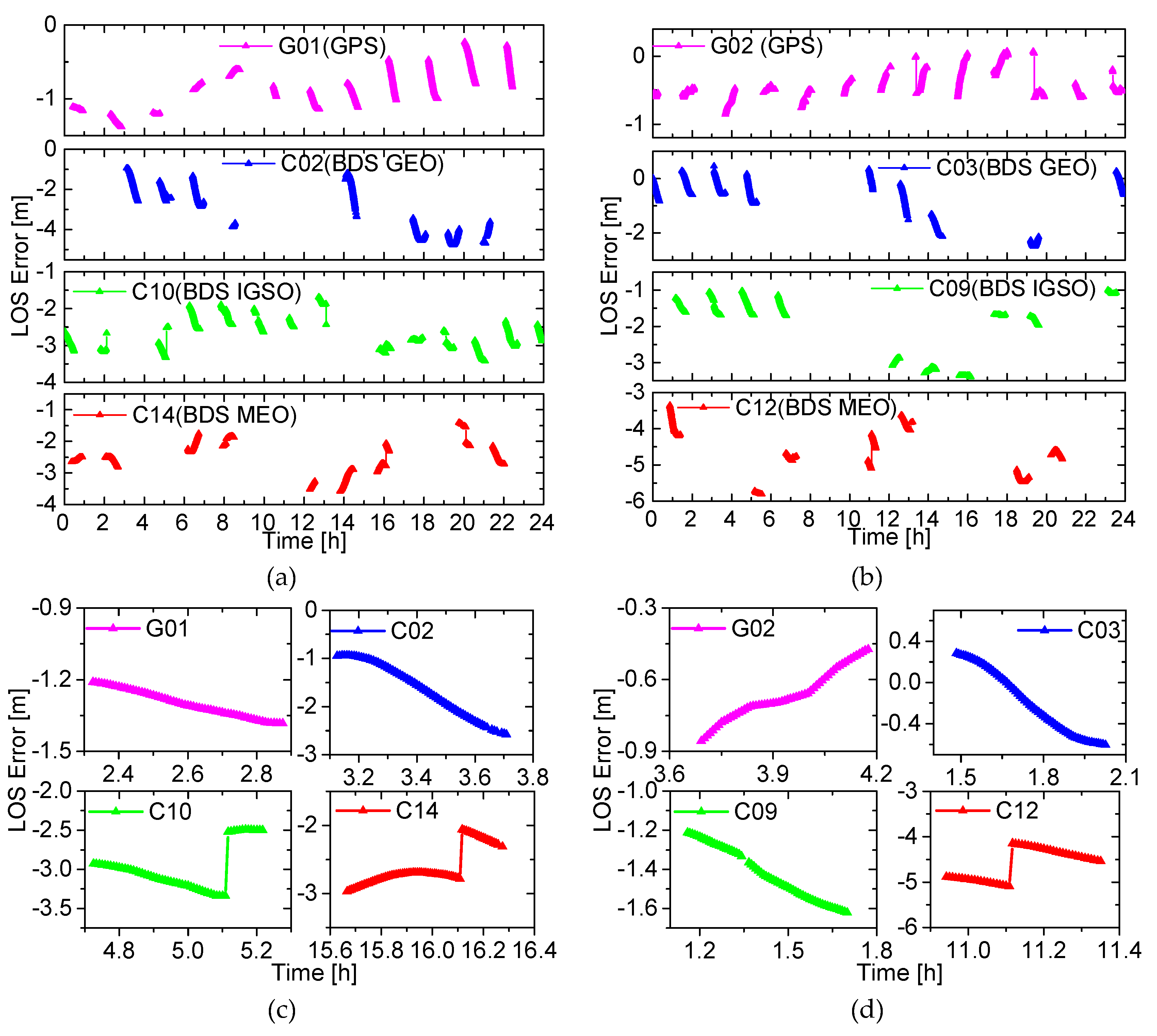
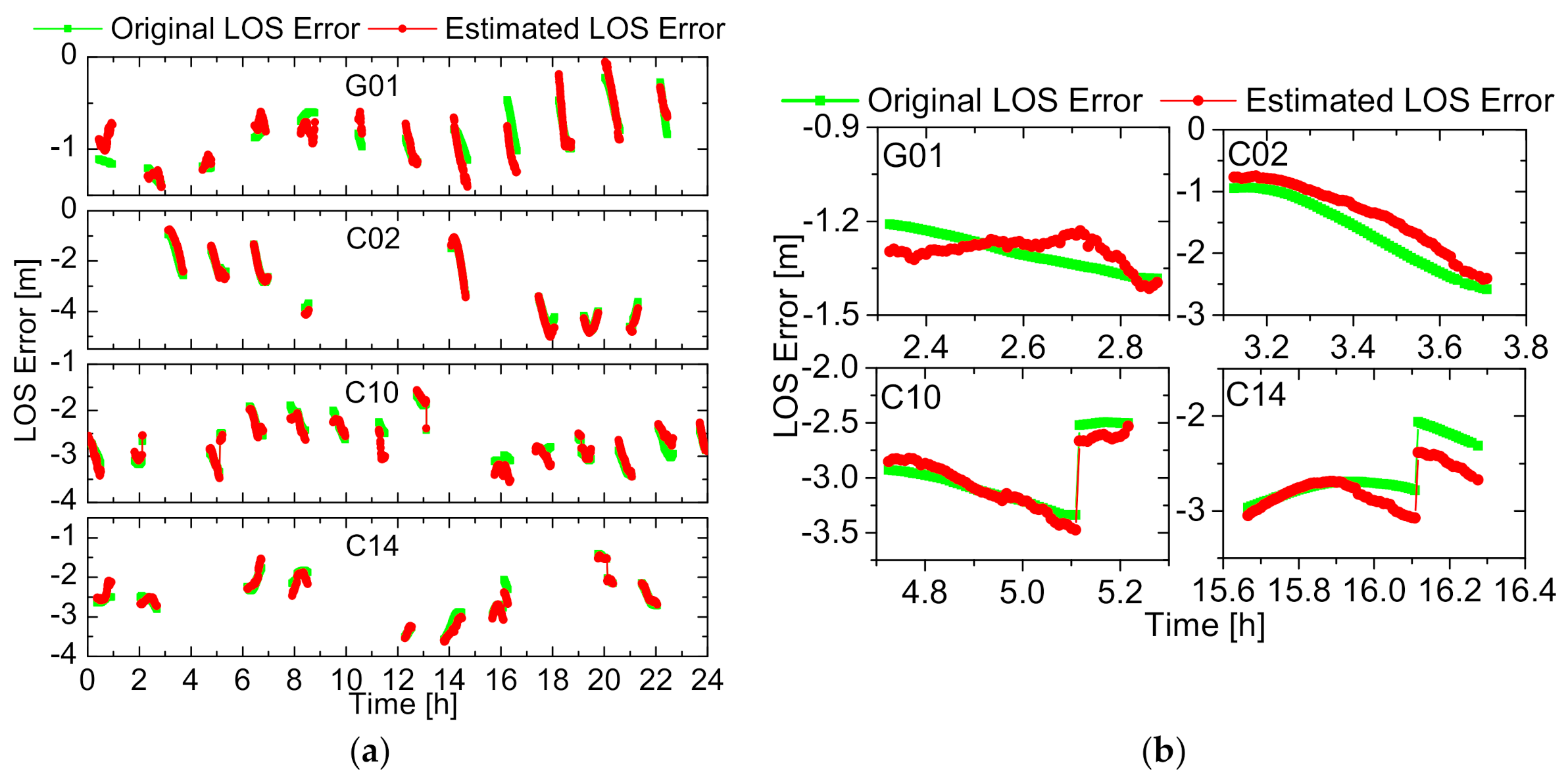
In consideration of different types of GPS/BDS satellites on different orbits, sub-graphs (a), (b), (c) and (d) of Figure 1 show the LOS errors of the four types of GPS/BDS satellites on day of year (DOY) 71, 2015. The thick lines represent the GPS or BDS satellites being tracked, and the intervals between consecutive lines indicate that the GPS/BDS satellite is not visible. Only for the tracking arc, the LOS error can be computed. The main property of the LOS error is that the LOS error in most tracking arcs is smooth and slowly changing regardless of the type of GPS/BDS satellite. In sub-graphs (a) and (b), the LOS error curves of two GPS satellites, G01 and G02, are displayed, and it is seen clearly that, whether being G01 or G02, the LOS error has the main property. Similarly, for C02 and C03 of BDS GEO, C10 and C09 of BDS IGSO and C14 and C12 of BDS MEO, the property holds. However, it cannot be ignored that there is a jump for some arcs. The second tracking arc of G01, the first one of C02, the third one of C10 and the seventh of C14 are zoomed in and showed in sub-graph (c), while the third one of G02, the second one of C03, the second one of C09 and the fourth of C12 are shown in sub-graph (d). As can be observed more clearly, for the C10, C12 and C14 satellites, the curves of the LOS errors are discontinuous and the jumps appear. This phenomenon was called the “ephemeris switch”. The reason for the jump is that the GNSS broadcast ephemeris is released every one or two hours and the orbit error has a jumping change when a new ephemeris is used. Since two satellites in a type (e.g., GPS or BDS MEO) of GNSS satellite have nearly the same error property, it is therefore reasonable to only choose G01, C02, C10 and C14, respectively, to represent GPS, BDS GEO, BDS IGSO and BDS MEO in the following analysis. In fact, choosing other satellites would result in almost the same conclusion.
On the basis of the practical analysis in the above, the random walk process is used to represent the pseudo-ambiguity in a tracking arc. For the epoch with the ephemeris switch, the sudden jump of the LOS error can be modeled by enlarging the variance of the corresponding pseudo-ambiguity additionally. For one pseudo-ambiguity , the random walk process can be expressed by a differential equation and the state propagation can be derived out easily [29]:
where is a white noise, is the power spectral density of the process noise, is the epoch interval and represents the pseudo-ambiguity at the epoch . is considered as white noise and is the variance of .
3.2. Stochastic Model Setting
Obviously, the power spectral density is an essential parameter for the stochastic model of the pseudo-ambiguity. The setting of decides whether the pseudo-ambiguity can be estimated reasonably and the LOS error could be reduced or not. If is too small, the pseudo-ambiguity will degenerate to a constant phase ambiguity, which means the LOS error can be estimated and absorbed. Conversely, if is too large, the constraint on the pseudo-ambiguity will be too loose, which means other errors may be absorbed into the estimated pseudo-ambiguity. All in all then, the inappropriate is harmful to the absorption of the LOS error, and then leads to the decrease in the RTOD accuracy. In theory, the variance of depends on the variation of the LOS error. Within a tracking arc, the power spectral density could be set based on the change rate of the true LOS error. An approximate relation between the change rate and the power spectral density can be derived easily:
The root mean square (RMS) statistics of the change rate for different GPS/BDS satellites on DOY 69–75, 2015, and the relevant power spectral density with the epoch interval of 30s () are listed in Table 1. The statistics values of for different types of GNSS satellites are different, and for BDS satellites they are larger than that of GPS satellites. In addition, the change rates of BDS IGSO satellites are close to that of BDS MEO satellites. Obviously, in order to reduce the LOS error effectively, it ought to be set appropriately and differently for different types of GNSS satellites.
However, it should be noted that the statistics value in Table 1 is not necessarily the optimal setting for the onboard RTOD. Therefore, a numerical search approach is adopted here to obtain the optimal setting of . The procedure of this approach is actually a series of numerical tests. First, the change rate varies step by step around the statistics value. Thus, the relevant power spectral density will also change gradually. With the power spectral density of different values, the corresponding onboard RTOD tests are carried out, and then the value resulting in the best orbit accuracy will be regarded as the optimal setting. Obviously, the optimal settings of three parameters should be searched separately for three types of GNSS satellites, namely GPS, BDS GEO and BDS IGSO/MEO satellites. According to Table 1, the statistics value of the change rate of the LOS error for different GNSS satellites is about 1.0 × 10⁻³–2.0 × 10⁻³ m/s, so the values of three parameters are set to be ranging from 10−9–10+1 m2/s along with the variation of change rate in the interval of 1.0×10⁻⁵─7.5×10⁻¹ m/s. In total, 20 sets of values are tested, which are listed in Table 2 and marked as S01─S20 for convenient expression in the following.
.
4. Orbit Results Analysis
A series of numerical tests will be carried out to search the optimal setting of the stochastic model of the pseudo-ambiguity parameter for each type of GPS/BDS satellite. Based on the onboard RTOD test results with the optimal stochastic model of pseudo-ambiguity, the absorption effect of the estimated pseudo-ambiguity on the LOS error in the GNSS broadcast ephemeris will be analyzed in-depth. At the same time, the analyses will be performed on the impact of GPS/BDS fusion on the availability of GNSS satellites, orbit accuracy, filter convergence and reliability of the onboard RTOD. In addition, it should be noted that the space-borne GPS/BDS data of the FengYun-3C satellite are not publicly available for users, and the data we can use are limited, so only three datasets that cover from DOY 69, 2015, through DOY 75, 2015, from DOY 33, 2018, through DOY 39, 2018, and from DOY 275, 2013, through DOY 300, 2013, will be processed by SATPODS to verify the effect of GPS/BDS fusion. It must be emphasized that the GNSS receiver onboard FengYun-3C can only track GPS satellites and the GEO, IGSO and MEO satellites of the earlier regional BDS-2, as per the receiver design back to 2013. In other words, the receiver on FengYun-3C is not able to track the operating BDS-3 satellites. At the same time, the main property of LOS errors caused by the GNSS broadcast ephemeris, shown in Figure 1, remains unchanged over the time. Therefore, the stochastic models of the pseudo-ambiguity are applicable to GNSS tracking data in any time, albeit the optimal settings are needed from time to time, which motivated the research presented in this paper. Hence, it can be inferred that the developed optimal setting method, which is experimented with these three datasets in 2013, 2015 and 2018, is generally applicable to any data at any other time, as long as the error property of the data is the same.
4.1. Numerical Search Tests
In the numerical search tests, the datasets of the FengYun-3C satellite that cover from DOY 69, 2015, through DOY 75, 2015, are processed by SATPODS. The software is capable of simulating the onboard operation scene. The strategies take the autonomy, timing and accuracy requirements of onboard RTOD into account. Only the GPS/BDS broadcast ephemeris is used, and the pseudo-ambiguities are estimated instead of the true constant ambiguities. Then, the dynamical models are simplified to the maximum extent to reduce the computational load. At the same time, the neglected perturbations, including the ocean and pole tide, earth radiation and relativistic effect, are small enough and have no notable effect on the real-time orbit accuracy. In addition, only simplified precession and nutation models and rapid predicted Earth orientation parameters (EOP) are applied for the transformation of coordinate systems. All the specific model settings are listed in Table 3. Furthermore, in order to assess the orbit accuracies from SATPODS, the precise orbit results generated by PANDA are used as references. The accuracy of the post-POD orbit results generated by PANDA are at the 2–4 cm level [23], so they can be treated as the reference to assess the real-time orbit accuracy.
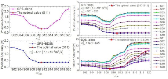
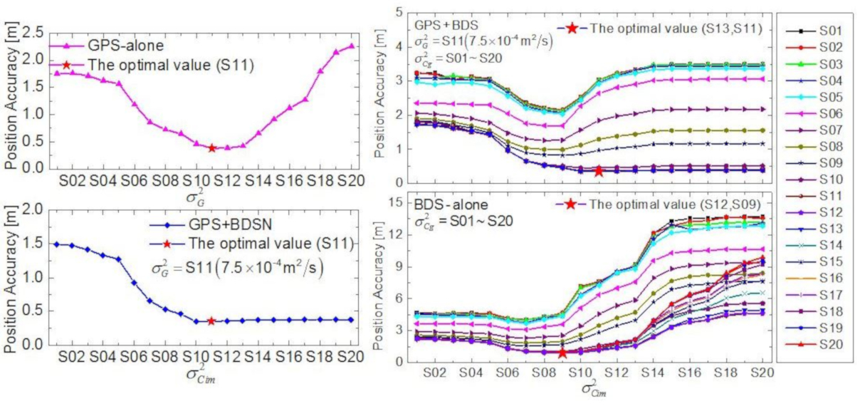
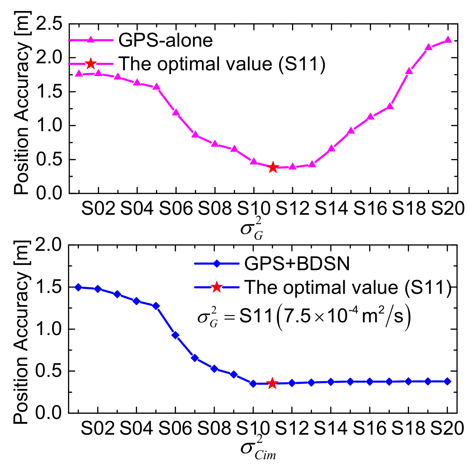
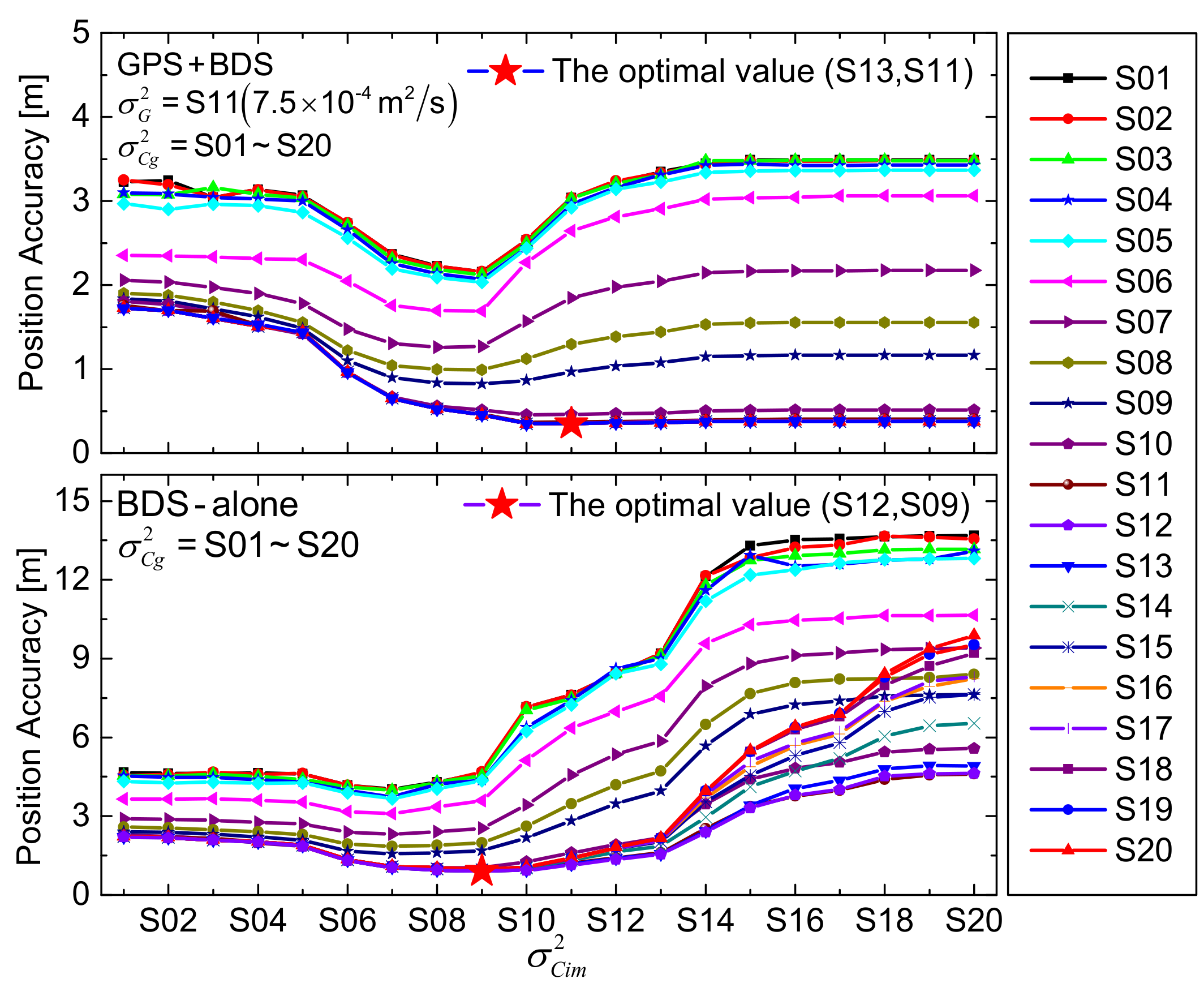
The optimal values of will be determined by the onboard RTOD tests with four types of solutions: (a) dual-frequency GPS ionosphere-free phase and pseudo-range measurements are used, and the solution is abbreviated as “GPS-alone”; (b) dual-frequency measurements of GPS and BDS IGSO/MEO satellites are used, and the solution is shorted as “GPS+BDSN”, where BDSN means the BDS GEO satellites are not included; (c) the solution using dual-frequency measurements of GPS and BDS satellites is shorted as “GPS+BDS”; (d) the solution only using BDS dual-frequency measurements is abbreviated as “BDS-alone”. The orbit accuracy of the onboard RTOD test will change when the values of vary. The orbit accuracies (3D RMS) of the onboard RTOD trials for the GPS-alone and GPS+BDSN solutions in DOY 69─75, 2015, are shown in Figure 2, and the results of the GPS+BDS and BDS-alone solutions are illustrated in Figure 3. As can be observed clearly, the orbit accuracy of the GPS-alone solution is improved from 1.757 to 0.381 m monotonically when increases from S01 to S11, but the accuracy deteriorates from 0.381 to 2.256 m if increases from S11 to S20 continuously. So, for the GPS-alone solution, S11 is the optimal value of , which corresponds to the best orbit accuracy of 0.381 m for 3D position. For the GPS+BDSN solution, is fixed with S11 being the optimal value of the GPS-alone solution, but varies from S01 to S20. The optimal is again S11 with which the best orbit accuracy of 0.349m is achieved. For the GPS+BDS solution, also takes the optimal value S11, and both and range from S01 to S20, therefore 400 trials will be conducted. The orbit accuracies of all 400 trials are shown in 20 curves, where each curve corresponds to a fixed value of and 20 values of . When take the values of (S13, S11), the best orbit accuracy of 0.348 m is obtained. Similarly, for the BDS-alone solution, both and change from S01 to S20, and the best accuracy of 0.899 m is achieved when take the value of (S12, S09).
Table 4 lists the optimal values of for the four solutions and the corresponding best orbit accuracies. In the GPS+BDS solution, the optimal values of for the BDS GEO and IGSO/MEO satellites are (S13, S11). The optimal setting for BDS IGSO/MEO satellites is the same as that of GPS satellites. The optimal value for BDS IGSO/MEO satellites in the GPS+BDSN solution is also the same as that in the GPS+BDS solution. This proves the consistency of pseudo-ambiguity stochastic models for the same types of GNSS satellites. However, if only BDS measurements are used, the optimal values of are (S12, S09), not (S13, S11), and a merely inferior orbit accuracy of 1.164 m is obtained if (S13, S11) are adopted. The different optimal values of for BDS satellites in the GPS+BDS and BDS-alone solutions demonstrate that the stochastic model setting of pseudo-ambiguity not only depends on its own characteristics but also relates to the measurements in the Kalman filter. In addition, the optimal setting of pseudo-ambiguity does not match the statistics value of based on the true LOS error in Table 1 very well. This also illustrates that the optimal setting of the stochastic model in the filter seems to be correlated with multiple factors, such as the characteristics of estimated parameters, the measurement errors, data distribution and so on.
4.2. Effect of Pseudo-Ambiguity
The numerical search tests indicate that the real-time orbit accuracy (3D RMS) of superior to 0.4 m for position could be achievable with the optimal stochastic model of pseudo-ambiguity in the GPS + BDS solution, which is much better than not only the accuracy of 1.0 m level in the solution of using single pseudo-range data [25] but also that of those GPS + BDS solutions with an inferior stochastic model setting. One reason for the accuracy improvement is that the measurement noise of carrier-phase data is very low. More importantly, the estimated pseudo-ambiguities absorb a large part of the LOS error caused by the GNSS broadcast ephemeris. Figure 4 shows the original true LOS error and the estimated LOS error fused in the pseudo-ambiguity of G01/C02/C10/C14 satellites on DOY 71, 2015. To separate the estimated LOS error from the pseudo-ambiguity, the true ambiguity in the pseudo-ambiguity is computed by the post-POD. As can be seen clearly, the two LOS error curves in sub-graph (a) present the same trend, indicating that the LOS error caused by the GNSS broadcast ephemeris is well absorbed through the estimate of the pseudo-ambiguity. The two LOS error curves in several special tracking arcs as shown in Figure 1 are also zoomed in and presented in sub-graph (b). Obviously, the LOS errors for both GPS and BDS satellites are well absorbed. Even though there is an ephemeris switch for the latter two arcs, the LOS errors are still well estimated due to enlarging the variance of the corresponding pseudo-ambiguity. All results demonstrate that the estimated pseudo-ambiguity can absorb the LOS error and improve the real-time orbit accuracy effectively.
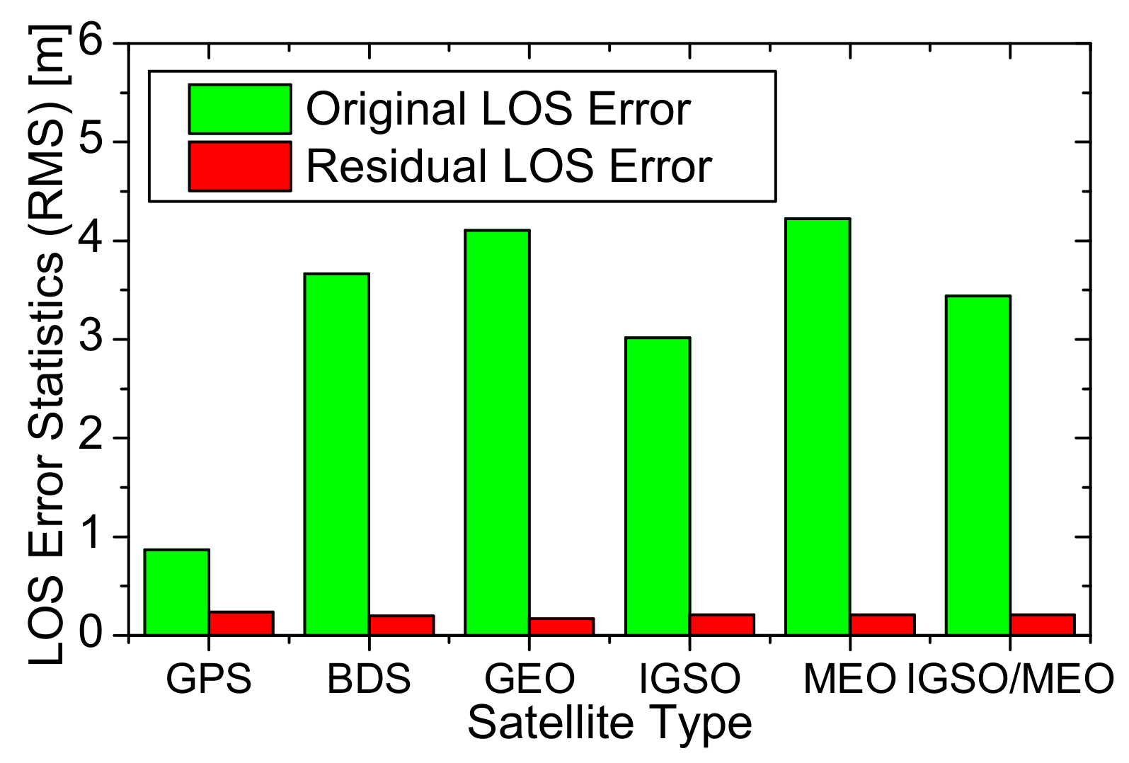
Figure 5 shows the overall statistics of the original LOS errors and the residuals after pseudo-ambiguity estimation for each type of GPS/BDS satellite at DOY 69–75, 2015. As can be observed, the original LOS error statistic (RMS) of GPS satellites is 0.869 m and most of the LOS errors are absorbed into the estimated pseudo-ambiguity parameters, so the residual LOS errors are reduced to 0.236 m. The original LOS errors of BDS satellites are up to 3–5 m, which is caused by the poor orbit and clock accuracy of the BDS broadcast ephemeris, and the different reference clock in the broadcast ephemeris and GFZ’s precise clock products. Although the difference of the reference clocks is not excluded in the original LOS errors, it integrates into the estimated receiver clock and has no effects on the absorption of the pseudo-ambiguity. According to the statistics, the residual LOS errors of all BDS satellites are only 0.197 m, of which 0.172 m for GEO and 0.207 m for IGSO/MEO satellites. The reason for the slightly smaller residual LOS error of BDS satellites compared to that of GPS satellites is probably that the BDS measurements do not play a leading role for the GPS/BDS fusion solution. When GPS measurements are used, other estimated common parameters such as position and receiver clock are constrained tightly. Thus, with the constrained common parameters, the LOS error could be absorbed into the estimated pseudo-ambiguities of BDS satellites more effectively once BDS measurements are added. As a whole, the residual LOS errors of GPS/BDS satellites are reduced to the 0.2 m level due to the absorption effect of the pseudo-ambiguity, which is a contributing factor to the orbit results with the accuracy of 0.348 m for the GPS + BDS solution.
4.3. Impact of GPS/BDS Fusion
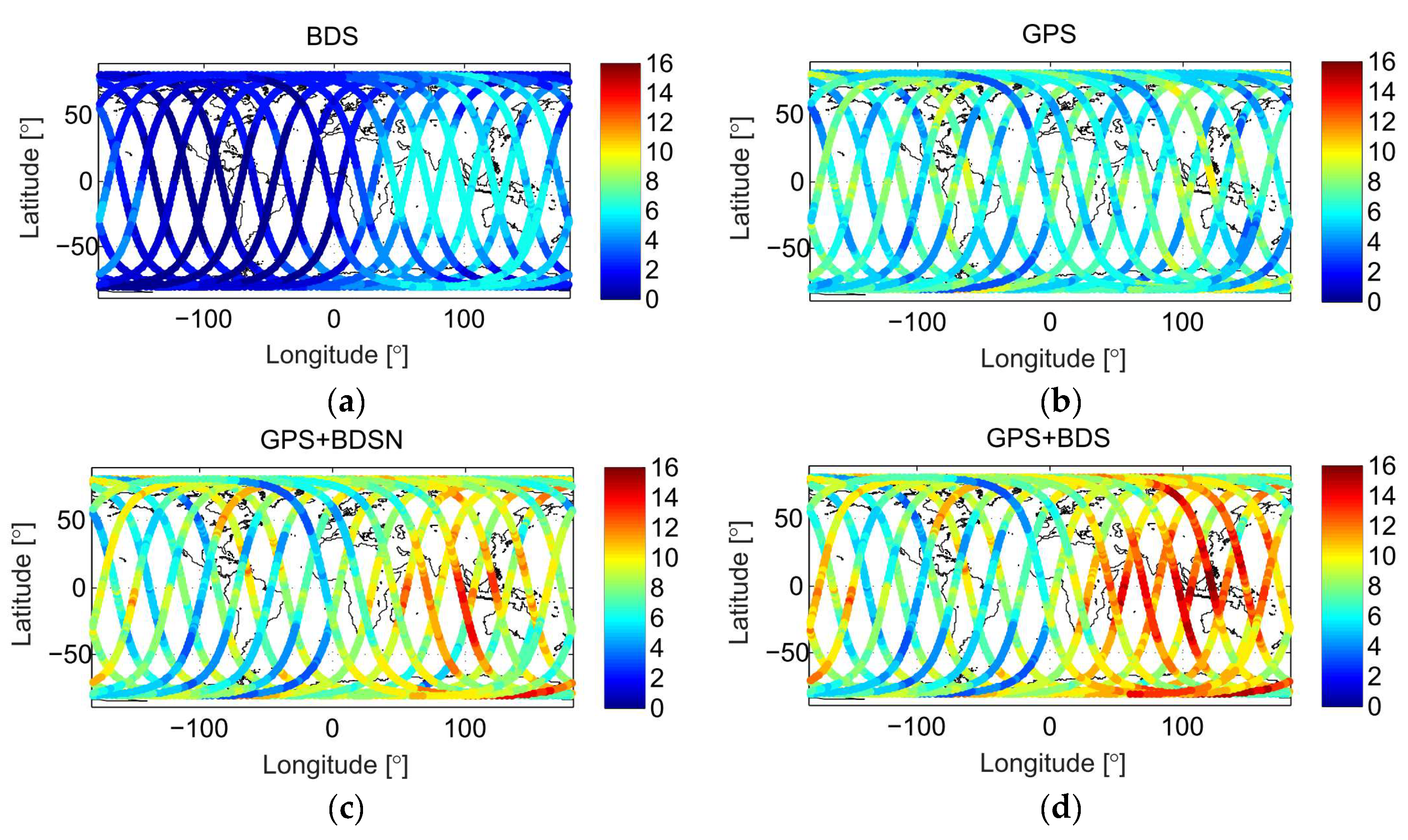
The most intuitive difference of different GPS/BDS fusion solutions is reflected in the number of tracked GNSS satellites, which is shown in Figure 6. For the GPS/BDS receiver onboard the FengYun-3C satellite, only the BDS-2 regional navigation system could be tracked. Thus, it can only observe four–six BDS satellites in the Asia/Pacific region and less than four satellites in other regions for the BDS-alone solution. GPS is a global navigation system with full operational capability, so more than four GPS satellites can be tracked by FengYun-3C in most places of the world. Compared to the GPS-alone or BDS-alone solution, the GPS + BDSN and GPS+BDS solutions increase the number of tracked GNSS satellites notably, especially in the Asia/Pacific region where GEO/IGSO satellites of BDS are tracked easily and two–six BDS satellites are added.
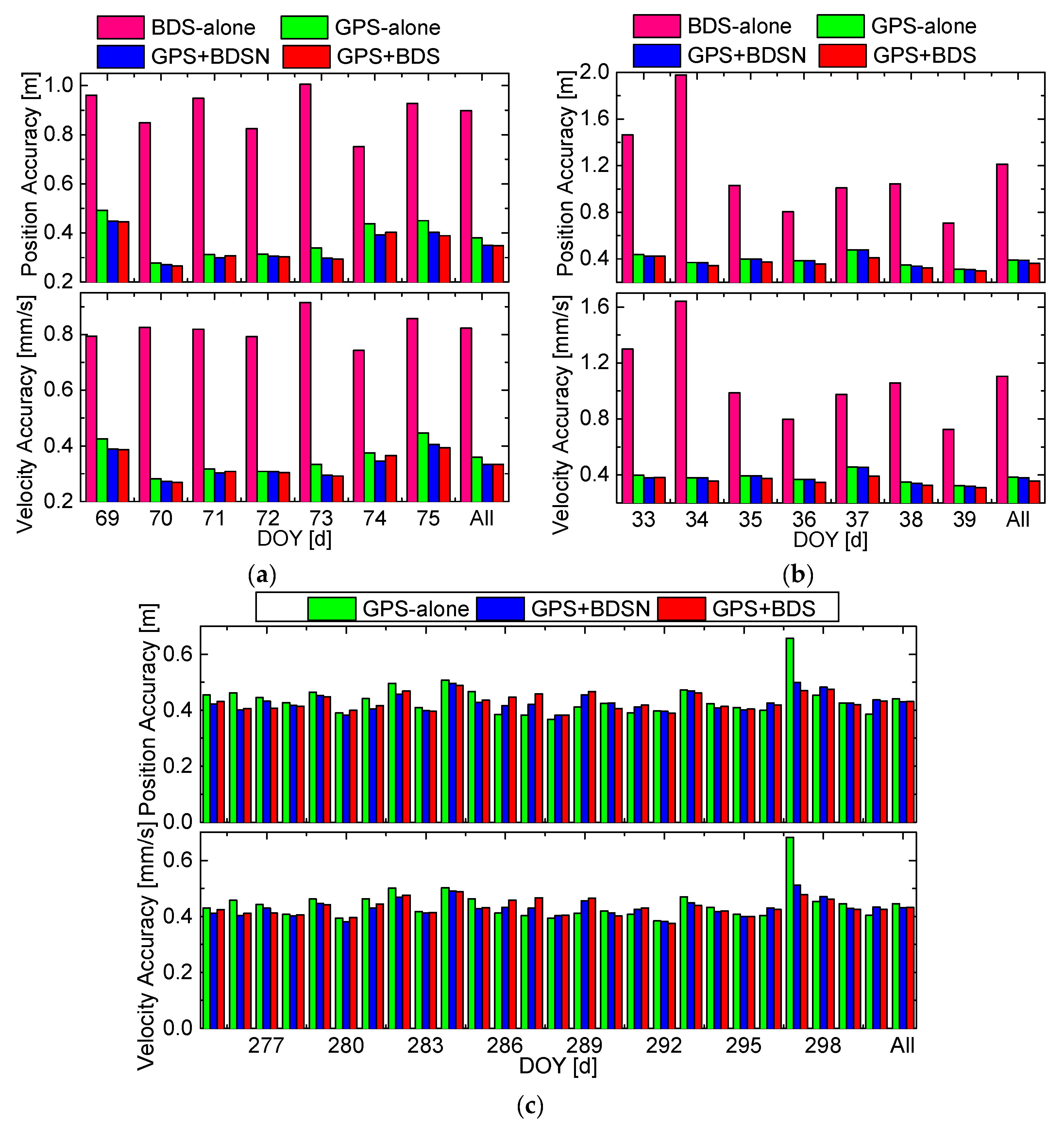
One should note that the increase in the number of tracked GNSS satellites does not mean the same increase for the real-time orbit accuracy. The daily position and velocity accuracies (3D RMS) with four GPS/BDS fusion solutions at DOY 69–75, 2015, DOY 33–39, 2018, and DOY 275–300, 2013, are shown in Figure 7, respectively. The label “All” is for the whole interval. According to sub-graphs (a) and (b), if only using BDS measurements, due to a few tracked BDS satellites and the obvious orbit and clock errors caused by the BDS broadcast ephemeris, the daily orbit accuracy is between 0.7 and 2.0 m for position and 0.7 and 1.7 mm/s for velocity. If only using GPS measurements, the daily orbit accuracy is improved dramatically by 0.3–0.5 m for position and 0.3–0.5 mm/s for velocity. Obviously, the orbit accuracy of using GPS-alone data is fairly superior to that of using BDS-alone data. However, the orbit accuracies of GPS + BDSN and GPS + BDS solutions are only slightly better than those of using GPS-alone data. For example, the overall 3D position accuracies of using GPS measurements at DOY 69–75, 2015, and DOY 33–38, 2018, are 0.381 and 0.392 m, while those of using GPS + BDS measurements are 0.348 and 0.363 m, which are only improved by 3.3 and 2.9 cm, respectively. The same conclusion can also be obtained from the orbit accuracy comparisons at DOY 275–300, 2013, as shown in sub-graph (c). The overall position accuracy in the whole 26-day interval for the GPS-alone and GPS + BDS solutions is 0.440 and 0.430 m, respectively, where the accuracy is only marginally better by 1.0 cm. The daily results demonstrate that the inclusion of BDS measurements could only slightly improve the accuracy by 1–3 cm, and if GPS measurements have been already used, the BDS measurements do not play a major role in the GPS/BDS fusion solutions. In addition, it should be noted that the difference between the GPS + BDSN and GPS + BDS solutions is also small. This indicates that there is no obvious orbit accuracy degradation or improvement, no matter whether BDS GEO satellites are involved or not.
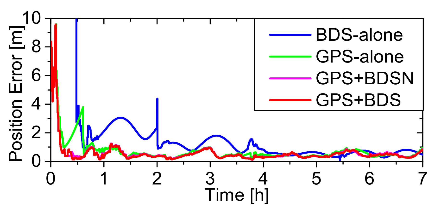
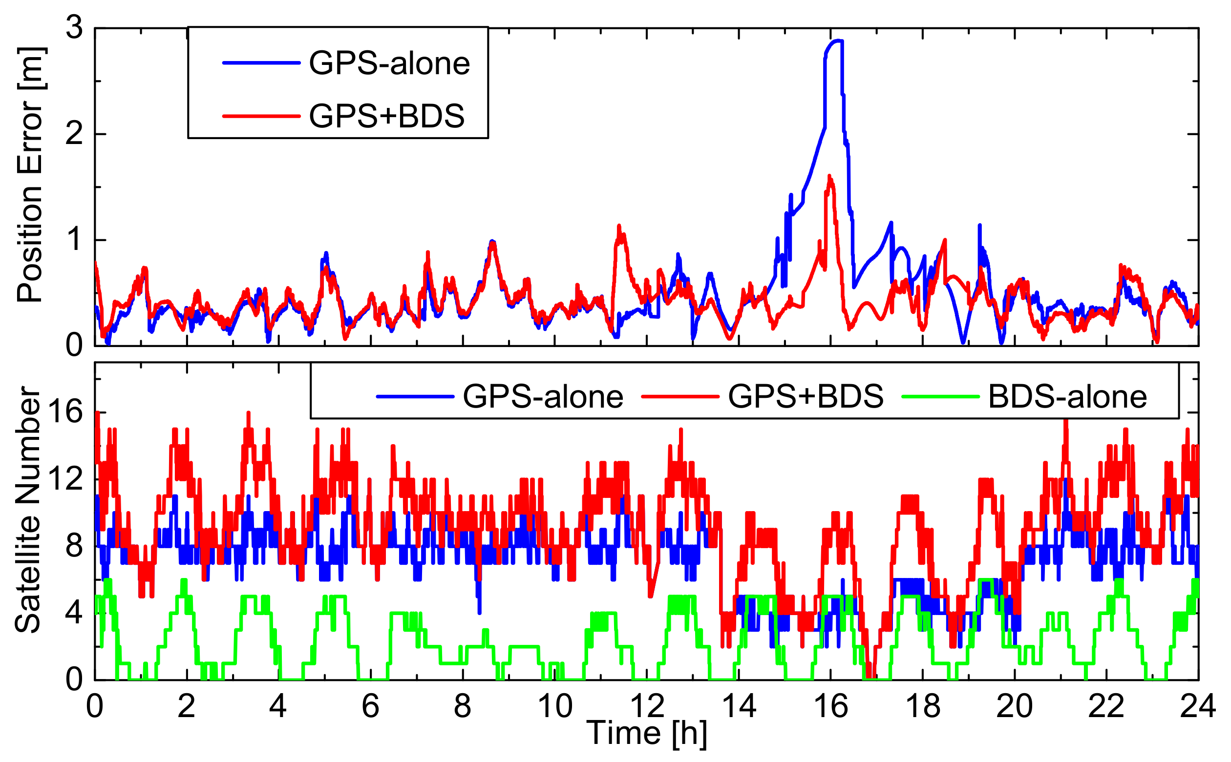
The small increase seems to be of little significance or even meaningless from the view of accuracy, but the fusion of GPS/BDS data is able to speed up the convergence of the Kalman filter. Figure 8 shows the 3D position error curves of the four GPS/BDS fusion solutions at the convergent stage of the filter. If only using BDS measurements, the filter needs about 4 h for the position error to converge to less than 1.0 m, and it requires about 1 h to converge to 1.0 m when only using GPS measurements, while the convergent time decreases dramatically to 0.5 h for the GPS/BDS fusion solutions. More importantly, the main advantage of the GPS/BDS fusion is not the orbit accuracy improvement or shortened convergence time, but the improved reliability of the onboard RTOD. Figure 9 shows the position errors of the GPS-alone and GPS + BDS solutions and the corresponding number of the tracked GPS and BDS satellites at DOY 297, 2013. In an abnormal arc that covers 14–20h, only two–six with an average of 2.8 GPS satellites are tracked. Thus, the position error of the GPS-alone solution is up to 3.0 m. The inclusion of BDS satellites increases the number of tracked GNSS satellites to 2–12 and an average of 5.2. The position error is suppressed to less than 1.5 m dramatically. It is obvious that the GPS + BDS solution guarantees the orbit accuracy in the anomalous arc. Although the anomalous arcs may not occur often, it can be generally concluded that the GPS/BDS fusion improves the reliability and availability of orbit results.
5. Application Prospect Discussion
A numerical search approach is presented in this paper to acquire the optimal setting of the power spectral density for the estimated pseudo-ambiguity parameters of different types of GNSS satellites. With the optimal setting, the real-time orbit accuracies (3D RMS) of 0.3–0.5 m for position and 0.3–0.5 mm/s for velocity are obtained for the FengYun-3C satellite when processing the space-borne GPS/BDS data. In practical applications, the similar numerical search tests could be carried out for a certain LEO satellite equipped with a GNSS receiver first, and then the searched optimal power spectral density of the pseudo-ambiguity can be adopted and uploaded for the onboard RTOD processing of this LEO satellite. Since the space-borne GNSS data condition and orbital characteristics for a specific LEO satellite and the LOS error variation in the broadcast ephemeris of a GNSS generally remain stable within a certain period, the re-prepared optimal value would be effective for a long time. Therefore, the numerical search approach is applicable to obtain the optimal stochastic model for onboard RTOD processing.
The GPS/BDS fusion could increase the number of tracked GNSS satellites effectively. Although the GPS/BDS fusion only improves the real-time orbit accuracy slightly by 1–3 cm, it could speed up the convergence of the onboard RTOD filter significantly. More importantly, it could make more GNSS satellites be observed to suppress the local variation of real-time orbit errors and improve the reliability and availability of the onboard RTOD, especially in some abnormal arcs where only a few GPS satellites are tracked. Due to the comprehensive advantage of multi-GNSS fusion in the availability of GNSS satellites, orbit accuracy, filter convergence and reliability of the onboard RTOD, more and more LEO satellites, even the large-scale LEO constellations, are expected to be equipped with the space-borne multi-GNSS receiver. In addition, although only the poor real-time orbit accuracy with 0.7–2.0 m for position and 0.7–1.7 mm/s for velocity could be achieved for the BDS-alone solution due to the few tracked regional BDS-2 satellites, it is expected to be improved along with the utilization of the BDS-3 global navigation system onboard LEO missions.
6. Summary and Conclusions
We present the onboard RTOD algorithm and experiments using space-borne GPS/BDS measurements of the FengYun-3C satellite. In the RTOD algorithm, a new pseudo-ambiguity parameter, which combines the constant phase ambiguity, the orbit and clock offset error of the GPS/BDS broadcast ephemeris in the line-of-sight (LOS), is defined and estimated in order to reduce the negative effect of the LOS error on onboard RTOD. The stochastic model setting of pseudo-ambiguity decides whether the pseudo-ambiguity can be estimated reasonably and the LOS error could be reduced or not. For different types of GPS/BDS satellites, the LOS errors show different variation properties, and accordingly, the stochastic model of pseudo-ambiguity is set separately and differently. A numerical search approach is presented to obtain the optimal setting of the power spectral density for each type of GNSS satellite by a series of tests. With the optimal setting, the best real-time orbit accuracies (3D RMS) of 0.3–0.5 m for position and 0.3–0.5 mm/s for velocity are achievable when using GPS/BDS carrier-phase and pseudo-range measurements, which are much better than those of the solutions with the inappropriate setting. The error analysis illustrates that these notable accuracy improvements result from the absorption effect of the pseudo-ambiguity, namely that the large part of the LOS error caused by the GNSS broadcast ephemeris is fused into the estimated pseudo-ambiguity.
The different combinations of multi-GNSS have a different influence on the onboard RTOD. If only using BDS measurements, the position and velocity accuracies are at the 0.7–2.0 m and 0.7–1.7 mm/s levels, respectively. The poor performance is caused by the few tracked satellites for BDS which is only a regional system and the obvious orbit and clock errors in the broadcast ephemeris. However, compared with the GPS-alone solution, GPS/BDS fusion only increases the real-time orbit accuracy slightly by 1–3 cm. Despite the marginally improved accuracy, GPS/BDS fusion could speed up the convergence of the Kalman filter, and the time for the position error to converge to 1.0 m is shortened to about 0.5 h for the GPS/BDS fusion compared to 4.0 h for using BDS-alone data and 1.0 h for GPS-alone data. Furthermore, the main advantage of the GPS/BDS fusion is not the orbit accuracy improvement or shortened convergence time, but rather the ability to make more satellites be observed to suppress the local variation of orbit errors and improve the reliability and availability of the onboard RTOD, which is particularly important when only a few GPS satellites are tracked in some abnormal arcs.
In summary, with the optimal stochastic model of the pseudo-ambiguity, the real-time orbit accuracy at 0.3–0.5 m is feasible for the onboard RTOD using space-borne GPS/BDS carrier-phase and pseudo-range measurements and the broadcast ephemeris. The onboard RTOD algorithm and software with refined multi-GNSS data processing have been developed in this paper. With the continuous development of Earth observations, remote sensing, communications and navigation augmentation based on LEO satellites, the onboard RTOD system is expected to fly on more LEO missions to provide a real-time service.
Author Contributions
In this study, X.G. designed the algorithm, performed experiments and wrote this paper. J.S. and F.W. designed the software, performed experiments, analyzed data and edited the manuscript. X.L. supervised its analysis and edited the manuscript. All authors have read and agreed to the published version of the manuscript.
Funding
This research was funded by the National Natural Science Foundation of China (Nos. 91638203).
Acknowledgments
We are very grateful to the German Geosciences Research Center (GFZ) for providing the GPS/BDS precise orbit and clock products. We would like to thank the reviewers for their valuable comments and suggestions. Special thanks to the Meteorological Administration/National Satellite Meteorological Center (CMA/NSMC) of China for providing the space-borne GPS/BDS data of the FengYun-3C satellite.
Conflicts of Interest
The authors declare no conflict of interest.
References
- Wulder, M.A.; Coops, N.C. Satellites: Make Earth observations open access. Nature 2014, 513, 30–31. [Google Scholar] [CrossRef] [PubMed]
- Su, Y.; Liu, Y.; Zhou, Y.; Yuan, J.; Cao, H.; Shi, J. Broadband LEO Satellite Communications: Architectures and Key Technologies. IEEE Wirel. Commun. 2019, 26, 55–61. [Google Scholar] [CrossRef]
- Wang, L.; Lü, Z.; Tang, X.; Zhang, K.; Wang, F. LEO-Augmented GNSS Based on Communication Navigation Integrated Signal. Sensors 2019, 19, 4700. [Google Scholar] [CrossRef] [PubMed] [Green Version]
- Hart, R.C.; Hartman, K.R.; Long, A.C.; Lee, T.; Oza, D.H. Global Positioning System (GPS) Enhanced Orbit Determination Experiment (GEODE) on the Small Satellite Technology Initiative (SSTI) Lewis Spacecraft. In Proceedings of the 9th International Technical Meeting of the Satellite Division of The Institute of Navigation (ION-GPS-1996), Kansas City, MO, USA, 17–20 September 1996. [Google Scholar]
- Hart, R.C.; Long, A.C.; Lee, T. Autonomous Navigation of the SSTI/Lewis Spacecraft Using the Global Positioning System (GPS). In Proceedings of the Flight Mechanics Symposium, GSFC, Greenbelt, MD, USA, 19–21 May 1997. [Google Scholar]
- Goldstein, D.B. Real-Time, Autonomous Precise Satellite Orbit Determination Using the Global Positioning System. Ph.D. Thesis, University of Colorado, Boulder, CO, USA, October 2000. [Google Scholar]
- Reichert, A.; Meehan, T.; Munson, T. Toward Decimeter-Level Real-Time Orbit Determination: A Demonstration Using the SAC-C and CHAMP Spacecraft. In Proceedings of the ION-GPS-2002, Portland City, OR, USA, 24–27 September 2002. [Google Scholar]
- Gill, E.; Montenbruck, O.; Arichandran, K.; Tan, S.H.; Bretschneider, T. High-precision Onboard Orbit Determination for Small Satellites-the GPS-based XNS on X-SAT. In Proceedings of the 6th Symposium on Small Satellites Systems and Services, La Rochelle, France, 20–24 September 2004. [Google Scholar]
- Montenbruck, O.; Nortier, B.; Mostert, S. A miniature GPS Receiver for Precise Orbit Determination of the Sunsat 2004 Micro-Satellite. In Proceedings of the 2004 National Technical Meeting of The Institute of Navigation (ION NTM 2004), San Diego, CA, USA, 26–28 January 2004. [Google Scholar]
- Montenbruck, O.; Markgraf, M.; Naudet, J.; Santandrea, S.; Gantois, K.; Vuilleumier, P. Autonomous and Precise Navigation of the PROBA-2 spacecraft. In Proceedings of the AIAA/AAS Astrodynamics Specialist Conference and Exhibit, Honolulu, HI, USA, 18–21 August 2008. [Google Scholar]
- Montenbruck, O.; Swatschina, P.; Markgraf, M.; Santandrea, S.; Naudet, J.; Tilmans, E. Precision spacecraft navigation using a low-cost GPS receiver. GPS Solut. 2012, 16, 519–529. [Google Scholar] [CrossRef]
- Montenbruck, O.; Ramos-Bosch, P. Precision real-time navigation of LEO satellites using global positioning system measurements. GPS Solut. 2008, 12, 187–198. [Google Scholar] [CrossRef]
- Gong, X.; Wang, F.; Liu, W. A Novel Algorithm on Sub-meter Level Real-Time Orbit Determination Using Space-Borne GPS Pseudo-Range Measurements. Lect. Notes Electr. Eng. 2014, 305, 89–100. [Google Scholar]
- Wang, F.; Gong, X.; Liu, W. A novel decimeter-level real-time orbit determination algorithm using space-borne GPS measurements with separation and absorption of broadcast ephemeris error. Geomatics Inform. Sci. Wuhan Univ. 2015, 40, 1230–1236. [Google Scholar]
- Wang, F.; Gong, X.; Sang, J.; Zhang, X. A Novel Method for Precise Onboard Real-Time Orbit Determination with a Standalone GPS Receiver. Sensors 2015, 15, 30403–30418. [Google Scholar] [CrossRef] [PubMed] [Green Version]
- Gong, X.; Wang, F. Autonomous orbit determination of HY2A and ZY3 missions using space-borne GPS measurements. Geomatics Inform. Sci. Wuhan Univ. 2017, 42, 309–313. [Google Scholar]
- China Satellite Navigation Office. Development of the BeiDou Navigation Satellite System (Version 4.0). Available online: http://www.beidou.gov.cn/xt/gfxz/201912/P020191227430565455478.pdf (accessed on 31 December 2019).
- Langley, R.B. Innovation: GLONASS—Past, present and future. 2017. Available online: https://www.gpsworld.com/innovation-glonass-past-present-and-future/ (accessed on 1 November 2019).
- Benedicto, J. Directions 2020: Galileo moves ahead. 2019. Available online: https://www.gpsworld.com/directions-2020-galileo-moves-ahead/ (accessed on 14 December 2019).
- Zhao, Q.; Wang, C.; Guo, J.; Yang, G.; Liao, M.; Ma, H.; Liu, J. Enhanced orbit determination for BeiDou satellites with FengYun-3C onboard GNSS data. GPS Solut. 2017, 21, 1179–1190. [Google Scholar] [CrossRef] [Green Version]
- Li, M.; Li, W.; Shi, C.; Jiang, K.; Guo, X.; Dai, X.; Meng, X.; Yang, Z.; Yang, G.; Liao, M. Precise orbit determination of the Fengyun-3C satellite using onboard GPS and BDS observations. J. Geodesy 2017, 91, 1313–1327. [Google Scholar] [CrossRef] [Green Version]
- Li, X.; Zhang, K.; Meng, X.; Zhang, W.; Zhang, Q.; Zhang, X.; Li, X. Precise Orbit Determination for the FY-3C Satellite Using Onboard BDS and GPS Observations from 2013, 2015, and 2017. Engineering 2019, 6, 904–912. [Google Scholar] [CrossRef]
- Shi, C.; Zhao, Q.; Geng, J.; Lou, Y.; Ge, M.; Liu, J. Recent development of PANDA Software in GNSS Data Processing. In Proceedings of the International Conference on Earth Observation Data Processing and Analysis (ICEODPA), Wuhan, China, 28–30 December 2008. [Google Scholar]
- Montenbruck, O.; Gill, E. Satellite Orbits: Models, Methods and Application; Springer: Berlin, Germany, 2020. [Google Scholar]
- Wang, F. Theory and Software Development on Autonomous Orbit Determination Using Space-Borne GPS Measurements. Ph.D. Thesis, Wuhan University, Wuhan, China, November 2006. [Google Scholar]
- Gong, X. Key Technologies and Software toward Decimeter-LEVEL autonomous Orbit Determination with Space-Borne GPS Carrier-Phase Measurements. M.Sc. Thesis, Wuhan University, Wuhan, China, 2015. [Google Scholar]
- Liu, J.; Li, Z.; Wang, Y.; Sang, J. Theory and Applications of the GPS System; Beijing Surveying and drawing Press: Beijing, China, 1993. (In Chinese) [Google Scholar]
- Montenbruck, O.; Steigenberger, P.; Hauschild, A. Broadcast versus precise ephemeris—a multi-GNSS perspective. Gps Solut. 2015, 19, 321–333. [Google Scholar] [CrossRef]
- Schutz, B.; Tapley, B.; Born, G.H. Statistical Orbit Determination; Elsevier Academic Press: Burlington, MA, USA, 2004. [Google Scholar]
Figure 1.
Line-of-sight (LOS) errors of the Global Positioning System (GPS)/BeiDou Navigation Satellite System (BDS) satellites: (a) the LOS error curves of GPS (G01), geosynchronous Earth orbit (GEO) (C02), inclined geosynchronous Earth orbit (IGSO) (C10) and medium Earth orbit (MEO) (C14) satellites of BDS on DOY 71, 2015; (b) the LOS error curves of GPS (G02), GEO (C03), IGSO (C09) and MEO (C12) satellites of BDS on DOY 71, 2015; (c) the LOS error curves of the 2nd tracking arc of G01, the 1st one of C02, the 3rd one of C10 and the 7th of C14; (d) the LOS error curves of the 3rd tracking arc of G02, the 2nd one of C03, the 2nd one of C09 and the 4th of C12.

Figure 2.
The real-time orbit accuracies for different in the GPS-alone and GPS+BDSN solutions.

Figure 3.
The real-time orbit accuracies for different in the GPS+BDS and BDS-alone solutions.

Figure 4.
Comparison of the original true and estimated LOS errors: (a) the LOS errors caused by the broadcast ephemeris and estimated in pseudo-ambiguity on DOY 71, 2015; (b) the original and estimated LOS errors in a tracking arc.
Figure 4.
Comparison of the original true and estimated LOS errors: (a) the LOS errors caused by the broadcast ephemeris and estimated in pseudo-ambiguity on DOY 71, 2015; (b) the original and estimated LOS errors in a tracking arc.

Figure 5.
Comparison of original and residual LOS errors statistics.

Figure 6.
Number of tracked GPS/BDS satellites: (a) BDS-alone; (b) GPS-alone; (c) GPS and BDS IGSO/MEO fusion; (d) GPS and BDS fusion.
Figure 6.
Number of tracked GPS/BDS satellites: (a) BDS-alone; (b) GPS-alone; (c) GPS and BDS IGSO/MEO fusion; (d) GPS and BDS fusion.

Figure 7.
Orbit accuracies comparison for different GPS/BDS fusion solutions: (a) orbit accuracy statistics at DOY 69–75, 2015; (b) orbit accuracy statistics at DOY 33─38, 2018; (c) orbit accuracy statistics at DOY 275–300, 2013.
Figure 7.
Orbit accuracies comparison for different GPS/BDS fusion solutions: (a) orbit accuracy statistics at DOY 69–75, 2015; (b) orbit accuracy statistics at DOY 33─38, 2018; (c) orbit accuracy statistics at DOY 275–300, 2013.

Figure 8.
Position errors at the convergent stage for different GPS/BDS fusion solutions on DOY 69, 2015.
Figure 8.
Position errors at the convergent stage for different GPS/BDS fusion solutions on DOY 69, 2015.

Figure 9.
Position errors of GPS-alone and GPS/BDS fusion solutions and the number of tracked global navigation satellite system (GNSS) satellites on DOY 297, 2013.
Figure 9.
Position errors of GPS-alone and GPS/BDS fusion solutions and the number of tracked global navigation satellite system (GNSS) satellites on DOY 297, 2013.


Table 1.
The statistics of the change rate and power spectral density on DOY 69–75, 2015.
| Satellite | (m/s) | (m2/s) |
|---|---|---|
| GPS | 0.958 × 10⁻³ | 2.753 × 10⁻⁵ |
| BDS | 1.720 × 10⁻³ | 8.875 × 10⁻⁵ |
| BDS GEO | 1.986 × 10⁻³ | 1.183 × 10⁻⁴ |
| BDS IGSO | 1.472 × 10⁻³ | 6.500 × 10⁻⁵ |
| BDS MEO | 1.263 × 10⁻³ | 4.786 × 10⁻⁵ |
| BDS IGSO/MEO | 1.373 × 10⁻³ | 5.655 × 10⁻⁵ |
Table 2.
The values and corresponding marks of .
| Mark | (m/s) | (m2/s) | Mark | (m/s) | (m2/s) |
|---|---|---|---|---|---|
| S01 | 1.0 × 10⁻⁵ | 3.000 × 10⁻⁹ | S11 | 5.0 × 10⁻³ | 7.500 × 10⁻⁴ |
| S02 | 2.5 × 10⁻⁵ | 1.875 × 10⁻⁸ | S12 | 7.5 × 10⁻³ | 1.688 × 10⁻³ |
| S03 | 5.0 × 10⁻⁵ | 7.500 × 10⁻⁸ | S13 | 1.0 × 10⁻² | 3.000 × 10⁻³ |
| S04 | 7.5 × 10⁻⁵ | 1.688 × 10⁻⁷ | S14 | 2.5 × 10⁻² | 1.875 × 10⁻² |
| S05 | 1.0 × 10⁻⁴ | 3.000 × 10⁻⁷ | S15 | 5.0 × 10⁻² | 7.500 × 10⁻² |
| S06 | 2.5 × 10⁻⁴ | 1.875 × 10⁻⁶ | S16 | 7.5 × 10⁻² | 1.688 × 10⁻¹ |
| S07 | 5.0 × 10⁻⁴ | 7.500 × 10⁻⁶ | S17 | 1.0 × 10⁻¹ | 3.000 × 10⁻¹ |
| S08 | 7.5 × 10⁻⁴ | 1.688 × 10⁻⁵ | S18 | 2.5 × 10⁻¹ | 1.875 × 100 |
| S09 | 1.0 × 10⁻³ | 3.000 × 10⁻⁵ | S19 | 5.0 × 10⁻¹ | 7.500 × 100 |
| S10 | 2.5 × 10⁻³ | 1.875 × 10⁻⁴ | S20 | 7.5 × 10⁻¹ | 1.688 × 101 |
Table 3.
Strategies of the onboard real-time orbit determination (RTOD).
| Model | Relevant Setting |
|---|---|
| Measurement model | |
| GNSS data | Dual-frequency GPS/BDS carrier-phase and pseudo-range measurements (interval 30s) |
| GNSS orbit and clock | Broadcast ephemeris |
| Receiver clock | A receiver clock offset and a system bias between GPS and BDS |
| Ambiguity | Pseudo-ambiguity with a random walk process |
| Dynamical model | |
| Earth gravity field | EGM 2008 (45 × 45), neglect the time-varying part |
| N-body gravitation | Moon and Sun only, low-precision analytic method (position) |
| Earth and pole tide | Low-precision model, solid only |
| Ocean and pole tide | Neglected |
| Relativistic effects | Neglected |
| Atmosphere drag | Modified Harris–Priester model (density), fixed effective area, drag coefficient with a random walk process |
| Solar radiation pressure | Cannonball model, fixed effective area, radiation pressure coefficient with a random walk process |
| Earth radiation pressure | Neglected |
| Empirical acceleration | Three empirical accelerations in radial, along-track and cross with a first-order Gauss–Markov model |
| Reference frame | |
| Coordinate system | WGS84/CGCS2000 |
| Precession and nutation | IAU1976/IAU 1980 simplified model |
| Earth rotation parameter | Rapid predicted EOP in IERS Bulletin A |
Table 4.
The optimal values of and the corresponding orbit accuracies.
| Solutions | Orbit Accuracy (m) | ||||||
|---|---|---|---|---|---|---|---|
| R | A | C | 3D | ||||
| GPS-alone | S11 | - | - | 0.122 | 0.337 | 0.130 | 0.381 |
| GPS+BDSN | S11 | - | S11 | 0.111 | 0.309 | 0.119 | 0.349 |
| GPS+BDS | S11 | S13 | S11 | 0.110 | 0.308 | 0.118 | 0.348 |
| BDS-alone | - | S12 | S09 | 0.264 | 0.771 | 0.379 | 0.899 |
| - | S13 | S11 | 0.342 | 0.998 | 0.491 | 1.164 | |
Publisher’s Note: MDPI stays neutral with regard to jurisdictional claims in published maps and institutional affiliations. |
© 2020 by the authors. Licensee MDPI, Basel, Switzerland. This article is an open access article distributed under the terms and conditions of the Creative Commons Attribution (CC BY) license (http://creativecommons.org/licenses/by/4.0/).
Share and Cite
MDPI and ACS Style
Gong, X.; Sang, J.; Wang, F.; Li, X. LEO Onboard Real-Time Orbit Determination Using GPS/BDS Data with an Optimal Stochastic Model. Remote Sens. 2020, 12, 3458. https://0-doi-org.brum.beds.ac.uk/10.3390/rs12203458
AMA Style
Gong X, Sang J, Wang F, Li X. LEO Onboard Real-Time Orbit Determination Using GPS/BDS Data with an Optimal Stochastic Model. Remote Sensing. 2020; 12(20):3458. https://0-doi-org.brum.beds.ac.uk/10.3390/rs12203458
Chicago/Turabian StyleGong, Xuewen, Jizhang Sang, Fuhong Wang, and Xingxing Li. 2020. "LEO Onboard Real-Time Orbit Determination Using GPS/BDS Data with an Optimal Stochastic Model" Remote Sensing 12, no. 20: 3458. https://0-doi-org.brum.beds.ac.uk/10.3390/rs12203458
Note that from the first issue of 2016, this journal uses article numbers instead of page numbers. See further details here.