
A Novel Method for Refocusing Moving Ships in SAR Images via ISAR Technique


1
Department of Space Microwave Remote Sensing System, Aerospace Information Research Institute, Chinese Academy of Sciences, Beijing 100190, China
2
School of Electronic, Electrical and Communication Engineering, University of Chinese Academy of Sciences, Beijing 100049, China
*
Author to whom correspondence should be addressed.
Remote Sens. 2021, 13(14), 2738; https://0-doi-org.brum.beds.ac.uk/10.3390/rs13142738
Submission received: 4 June 2021
/
Revised: 27 June 2021
/
Accepted: 7 July 2021
/
Published: 12 July 2021
(This article belongs to the Topic High-Resolution Earth Observation Systems, Technologies, and Applications)
Abstract
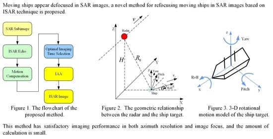
:As an active microwave remote sensing device, synthetic aperture radar (SAR) has been widely used in the field of marine surveillance. However, moving ships appear defocused in SAR images, which seriously affects the classification and identification of ships. Considering the three-dimensional (3-D) rotational motions (roll, pitch, and yaw) of the navigating ship, a novel method for refocusing moving ships in SAR images based on inverse synthetic aperture radar (ISAR) technique is proposed. First, a rectangular window is used to extract the defocused ship subimage. Next, the subimage is transformed into the ISAR equivalent echo domain, and the range migration and phase error caused by the identical movement of all ship scatterers are compensated. Then, the optimal imaging time can be selected by the maximum image contrast search method. Finally, the iterative adaptive approach (IAA) is used to obtain the image with high resolution. This method has satisfactory imaging performance in both azimuth resolution and image focus, and the amount of calculation is small due to the processing of subimages. Simulated data and Gaofen-3 real SAR data are used to verify the effectiveness of the proposed method.
1. Introduction
Synthetic aperture radar (SAR) plays an important role in the field of marine surveillance due to its all-weather and all-time imaging capability. Although stationary scenes can be well focused through traditional SAR imaging algorithms (e.g., Chirp Scaling, ), moving ships can be defocused in the SAR image, which seriously affects ship classification and identification. Therefore, the research on the refocusing of the moving ship has become extremely urgent.
The effects of slow moving targets on SAR imaging are studied in [1], where the velocity and acceleration of the moving target are considered, and two airborne moving target indication (AMTI) methods are summarized. In [2], the fractional Fourier transform (FrFT) is used to perform optimal processing and analysis of residual chirp signals, thus the azimuth velocity of the target can be estimated and the along-track defocus can be compensated. In [3], the compensation function of the ground moving target in the two-dimensional (2-D) frequency domain is derived, and a method based on maximum image contrast search is proposed to obtain the refocused image of the ground moving target. On the basis of [3], sparse parameter representation method is proposed in [4] to refocus the moving target, which can suppress asymmetric side-lobes and improve the image quality. Based on the estimation of Doppler parameters (the Doppler centroid and the Doppler rate), the target motion parameters can be obtained and the ship inverse synthetic aperture radar (ISAR) imaging is carried out in [5]. An ISAR refocusing method for SAR ship image based on the fast minimum entropy phase compensation (FMEPC) method is proposed in [6].
However, the above-mentioned imaging methods are proposed for the smoothly moving target model, which are not suitable for the ship with three-dimensional (3-D) rotational motions (roll, pitch, and yaw). Because the Doppler frequency of the ship with 3-D rotational motions is time-varying after motion compensation, it is difficult for the above methods to obtain a focused image for such ships.
The effects of rotational motions (roll, pitch, and yaw) on ISAR imaging of small craft are analyzed in [7]. Moreover, in [8], the effects of ship linear motion and rotational motions on SAR image are researched, and the imaging distortions can be characterized by four main types of transformations, namely translation, rotation, scaling, and shearing according to the analysis and experiments. In [9], the effect of six-degree-of-freedom oscillation of ship target on SAR imaging is studied, the phase compensation method is made by fitting ship attitude angles with multiple sinusoidal functions, however, the ship attitude parameters are generally unknown in practice. In [10], multiple sinusoidal functions are used to match rotation effects of the ship in geosynchronous SAR, however, parameter searching needs a lot of calculation.
For the ISAR imaging with long recorded live ISAR data, a maximum image contrast based automatic time window selection (MC-ATWS) technology is proposed in [11], it can automatic select the position and length of the time window that provides the ISAR image with the highest image contrast, therefore, the relatively stable time of movement can be selected by this method. This method plays an effective role in ISAR imaging of non-cooperative targets, but there is a trade-off between ideal azimuth resolution and image focus. An ISAR motion compensation method via image contrast based technique is proposed in [12]. The applications of [11,12] are further expanded in [13], and a complete ISAR processing flow is proposed to deal with the defocused non-cooperative targets in Cosmo-Skymed spotlight SAR images. Moreover, the contrast maximization based technique is also verified using Radarsat-2 single look complex (SLC) SAR image in [14]. A novel ISAR optimal imaging time interval (OITI) selection algorithm for marine targets based on sea dynamic prior information (SDPI) is proposed in [15], the optimal imaging instant (OII) and optimal imaging duration (OID) are determined by the effective rotational vector (ERV) and maximum contrast criterion, respectively, however, precise SDPI acquisition and the feasibility for real data need to be further investigated. The time window selection algorithm based on measured data is proposed in [16], however, it is only suitable for cooperative ships. Phase nonlinearity is used to select imaging frames where target 2-D motion is dominant enough to obtain focused ISAR images in [17,18], however, those methods need prominent scatterers. The time window selection algorithm based on Doppler frequency information is proposed in [19], but it is not robust due to the instantaneous frequency variation of a ship is different for different scatterers. The time selection method based on the tracking of specific scatterers is proposed in [20], this method searches for the suitable side view imaging moment and top view imaging moment by tracking different ship specific scatterers, however, it is difficult to track the specific scatterers especially in the case of high sea conditions. The slope-based frame selection method proposed in [21] selects the time instants better suited for top or side view image formation, it operates in the image domain by using the slopes of some extracted linear features, however, it is difficult to extract the linear features. The time selection algorithm based on the Doppler center frequency (DCF) is proposed in [22], and the time selection algorithm based on the Doppler spread (DS) technique is proposed in [23], this type of method needs to obtain multiple range Doppler (RD) images, which is time consuming and not suitable for high sea conditions.
A ship ISAR imaging algorithm based on the generalized radon-Fourier transform (GRFT) is proposed in [24] through a 3-D search of range, velocity, and acceleration in the range compression domain, although this method adopts a combination of coarse search and fine search, it still consumes a lot of calculation, in addition, this algorithm only models each point as a combination of velocity and acceleration, ignoring higher order terms. GRFT and gradient-based descent algorithm are used for maneuvering targets imaging in [25], and this method takes a tradeoff between imaging performance and computational efficiency. Joint time-frequency transform is proposed in [26] as an alternative to Fourier transform to solve the image blurring problem caused by time-varying Doppler frequency shift, which does not need to resort to sophisticated motion compensation algorithms, however, joint time-frequency transform suffers from resolution degradation when the short-time Fourier transform (STFT) is used or cross-term interference when the Wigner-Ville distribution (WVD) is used. In [27], squint minimization operation is implemented for the compensation of third range compression in high-squint SAR ship imaging, then WASH-CLEAN method is proposed to automatically focus ship scattering points with different swings, however it is time consuming and it mainly considers the effect of ship motion under low or moderate sea states. Parametric range instantaneous Doppler algorithms express the Doppler phase of the ship scatterers as polynomial functions of observation time and the polynomial model coefficients can be estimated by product high-order matched-phase transform (PHMT) [28], coherently integrated generalized cubic phase function (CIGCPF) [29], coherently integrated cubic phase function (CICPF) [29], bilinear extended fractional Fourier transform (BEFRFT) [30], etc. The Doppler frequency histories of ship scatterers in the observation time can be reconstructed based on the estimated motion parameters, however, such methods need a lot of calculation, meanwhile, error propagation effects exist when estimating the parameters with such methods.
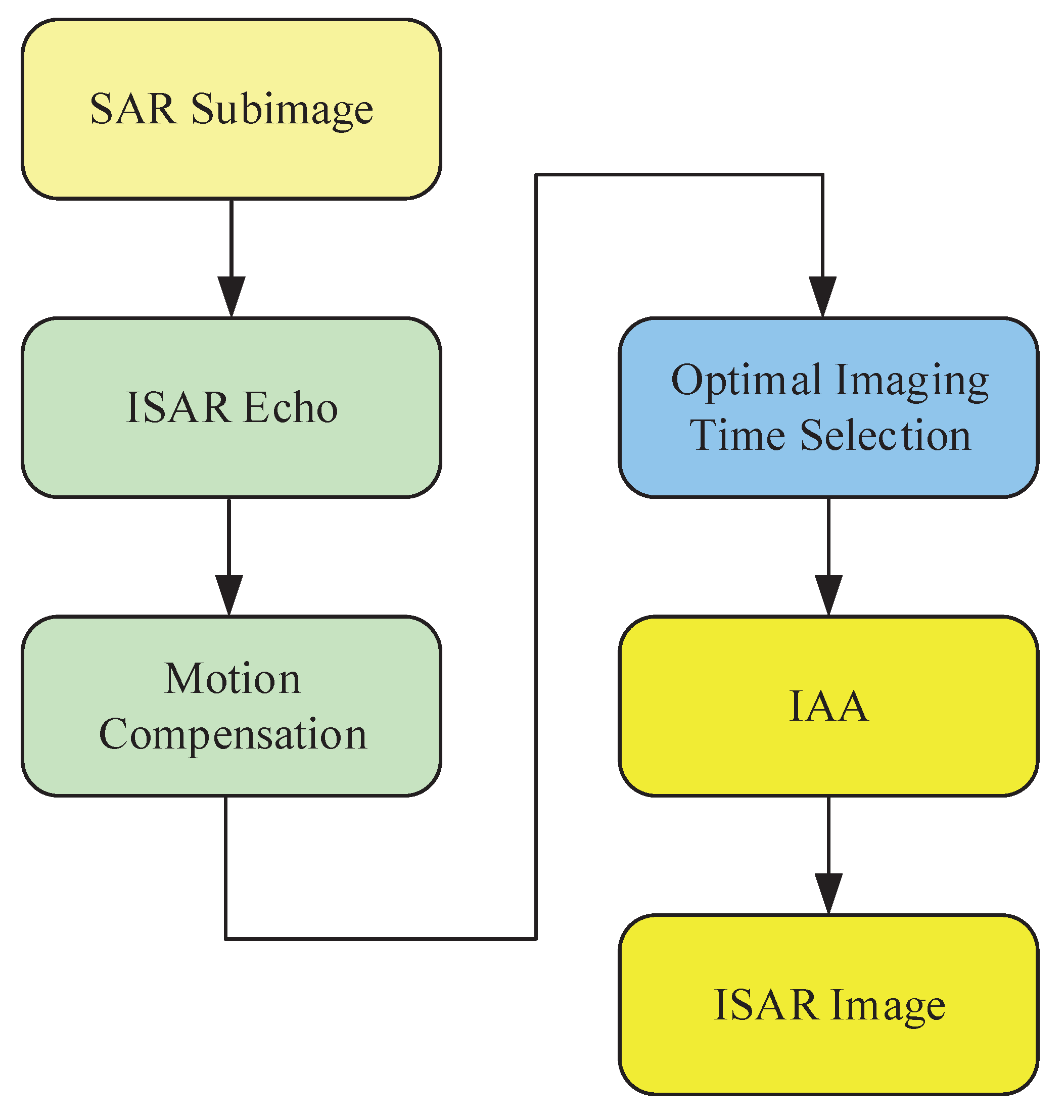
In the field of moving ship imaging, it is considered a very promising idea to process only the subimage which contains the defocused ship. This operation can bring many advantages. First, in the SAR image domain, the ship can be easily separated from the rest of the scene through many ship detection algorithms, in addition, processing subimage greatly saves computer resources, and the amount of calculation is significantly reduced. This paper considers the defocused navigating ship with 3-D rotational motions in the SAR image, the ISAR technique is used to image the ship, and the whole processing flow is based on the subimage, which contains the defocused ship. First, the detected ship is extracted through a rectangular window in the SAR image domain, next, the SAR subimage is transformed into ISAR equivalent echo domain through the azimuth inverse mapping (i.e., inverse fast Fourier transform (IFFT) in the azimuth direction) [31], and the motion compensation including range alignment and phase compensation is carried out, then, the optimal imaging time is selected through the maximum image contrast search method, finally, the iterative adaptive approach (IAA) [32] is used to obtain the focused image. The contradiction between time resolution and frequency resolution is alleviated, thus the proposed method has satisfactory imaging performance in both azimuth resolution and image focus for navigating ships with 3-D rotational motions.
Since the defocusing effect of the moving ship is a common phenomenon in SAR images, which severely limits the applications of SAR images, this study aims to propose a signal model of the navigating ship with 3-D rotational motions and refocus the moving ship with SAR subimage via ISAR technique, so as to provide a basis for ship classification and identification.
2. Geometry and Signal Model
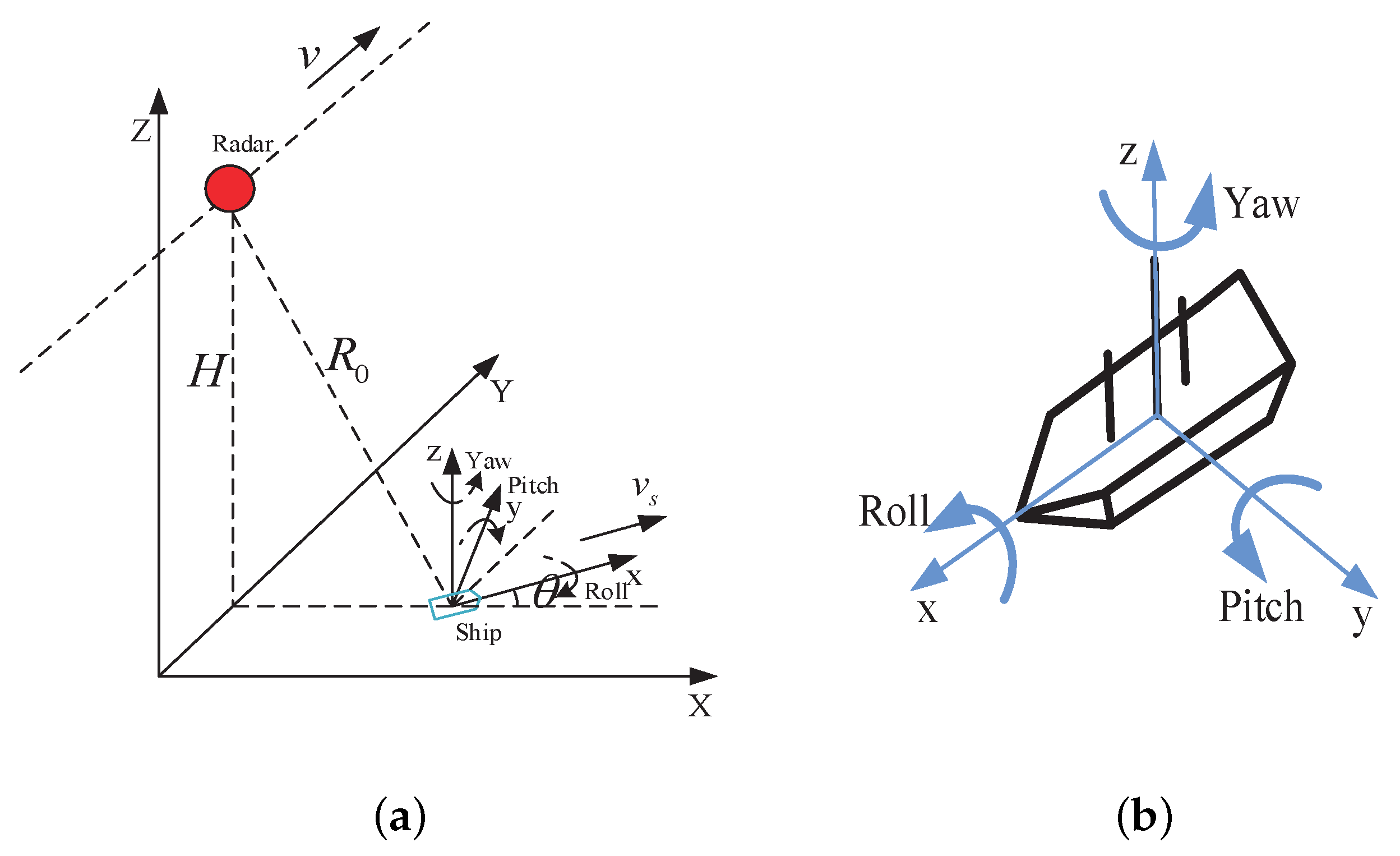
The motion model used in this paper includes velocity and 3-D rotational motions including roll, pitch, and yaw. The geometric relationship between the radar and the ship target is shown in Figure 1a, the 3-D rotational motion model of the ship target is shown in Figure 1b, the velocity of the radar relative to the ground is v, the velocity of the ship relative to the ground is , the angle between the orientation of the ship and the X axis is .
For a ship scatterer in the ship coordinate system, its time-varying coordinates is .
where t is the azimuth time, , , and denote the angle of roll, pitch, and yaw, respectively, which can be expressed as
where , , and are the amplitude, period, and central time phase of the roll angle, , , and are the amplitude, period, and central time phase of the pitch angle, , , and are the amplitude, period, and central time phase of the yaw angle.
The coordinates of the scatterer in the global, earth-fixed coordinate system are .
where is the distance between the radar and the ship at central time, H is the flight altitude of the radar.
Then, the distance between the scatterer and the radar can be written as
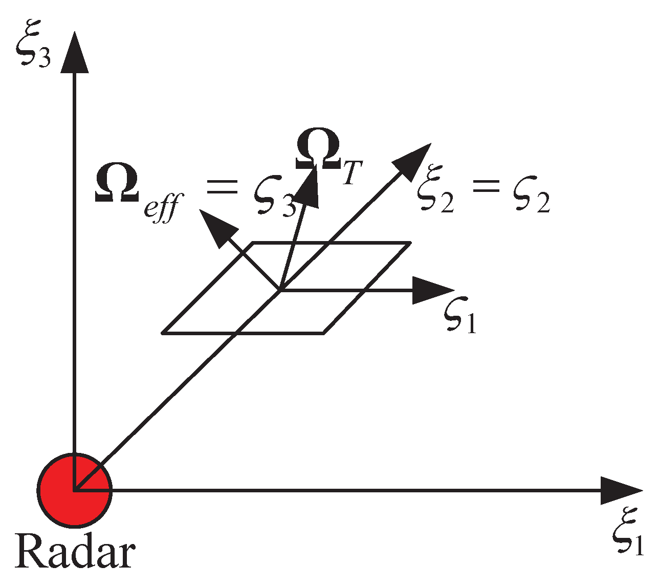
As for ISAR imaging, the geometry is shown in Figure 2, the total angular rotation vector is , which is caused by the target rotation due to both the translational and angular motions, The projection of on the plane orthogonal to the radar line of sight (LOS) is called effective rotation vector , which contributes to the target aspect angle variation. The imaging plane is orthogonal to the effective rotation vector [13].
After range compression, the echo signal can be written as
where c is the velocity of light, I is the number of ship scatterers, is a complex constant belonging to scatterer i, t is the azimuth time, T is the observation time, is the range frequency, B is the range bandwidth, is the carrier frequency, is the unit vector that identifies the LOS, is the vector that identifies a scatterer on the target. represents the distance between the radar and the rotational center of the target, which is the main factor causing the target range migration and azimuth phase error, so needs to be compensated before azimuth imaging, the operation to compensate the named motion compensation.
Then, the Doppler frequency can be calculated from
where is the wavelength. After the phases introduced by the of the rotational center are compensated, the Doppler frequencies caused by the roll, pitch, and yaw rotational motions are analyzed in this paper, considering the complex expression of 3-D rotational motions of the ship, the rotational motions are analyzed separately.
Assume the ith scatterer coordinates of the ship is in the ship coordinate system, its time-varying coordinates caused by roll is , then
The Doppler frequency caused by roll is
where , , then
where
Similarly, the Doppler frequencies caused by pitch and yaw are
where and , when the , , and are small enough, then
Combining the Doppler frequencies of roll, pitch, and yaw, then
Thus, the Doppler frequency variation introduced by 3-D rotational motions of each scatterer is the superposition of multiple sinusoidal signals, which allows us to find the optimal imaging time when the Doppler frequency is approximately constant.
3. Method
In this section, the proposed method for refocusing moving ships is described, it is based on ISAR technique with SAR subimage and the flowchart of the proposed method is shown in Figure 3.
3.1. Motion Compensation
The motion compensation should be done before azimuth imaging, which contains range alignment and phase compensation [6,31].
For the rotational center of the ship, its relative distance to the radar can be expressed as
Since the azimuth velocity of the ship is always far smaller than the velocity of the radar (especially for the satellite platform), it can be neglected when analyzing the range migration (assume the range migration introduced by the azimuth velocity is compensated through SAR imaging). So the range migration of the moving ship relative to the radar is mainly caused by the slant range velocity, which is , however, the phase introduced by cannot be neglected, which named Doppler rate mismatch in SAR imaging. So in the SAR SLC image, moving target will be defocused in the azimuth direction, and the energy will spread to different range cells at the same time.
The subimage can be transformed into azimuth time range frequency domain through inverse algorithm, since the ship always occupies a small range cells, the center range of the subimage can be used as the reference range of the inverse algorithm, and the inverse Stolt interpolation is neglected to decrease the computation time. Note that zero padding is required in this step. In order to achieve range alignment, the compensation function can be given by
Then, the SAR image can be obtained by algorithm and the Stolt interpolation is also neglected here, then, the entropy of the sum range profile (SRP) [33] defined in the ISAR equivalent echo domain can be used as the evaluation function of range alignment.
Then, can be obtained through search, it corresponds to the value at which the entropy function is minimized. Finally, after coarse alignment, minimizing the entropy of the average range profile (ARP) [34] in the ISAR equivalent echo domain can be used for fine adjustment.
After the range alignment, the phase compensation should be carried out [6], which is an important step and second-order and higher-order phase errors should be compensated in this step, since they seriously affect the quality of focus. There are many phase compensation algorithms for SAR and ISAR, such as Doppler centroid tracking (DCT) [35], phase gradient autofocus (PGA) [36], fast minimum entropy phase compensation (FMEPC) [6,37], and maximum-contrast phase adjustment [37]. Since image entropy is an important indicator for the image overall focusing effect, the FMEPC algorithm is used in this paper to compensate the phase error. FMEPC estimates the phase error by minimizing image entropy iteratively and the specific principle is as follows.
Assume that the ISAR image is obtained by
where U and N are the number of azimuth cells and range cells, respectively, and , denotes the equivalent echo after range alignment, k denotes the index of azimuth cells, denotes the compensation phase, the entropy of the ISAR image [37] is
Since is a constant, entropy can be redefined as [37]
To minimise , the derivative of with respect to needs to be 0, which can be written as
According to [37], the derivative of with respect to can be obtained as
Thus, , and denotes phase calculation operation.
The main steps of FMEPC are as follows.
- 1.
- Initialize the compensation phase , ;
- 2.
- According to the Equation (16), The echo after range alignment can be used to obtain ISAR image ;
- 3.
- Calculate the entropy of ISAR image, and set the termination condition (e.g., if the entropy difference between this iteration and the previous iteration is small, then, break; otherwise, go to next step);
- 4.
- Calculate the value of in this iteration process;
- 5.
- Update the compensation phase , , go to step 2.
Note that the compensation phase can be initialized through DCT method. After motion compensation, it can be considered that the translation of the ship is compensated, some ships with smooth motion can be focused well, nevertheless, the ship with 3-D rotational motions cannot be focused due to the time-varying Doppler frequency, which needs further processing, and the final focusing performance will depend on the ISAR azimuth imaging method.
3.2. Image Contrast Based Optimal Imaging Time Selection
After the motion compensation of the ISAR echo, it can be considered that the phase error introduced by the identical motion of the ship scatterers relative to the radar is compensated. The rest 3-D rotational motions of the various ship scatterers around the center of rotation will cause the time-varying Doppler, and the time-varying Doppler will make the ship defocused. However, in some short time intervals, the Doppler frequency variation of the ship scatterers is nearly stable. It is completely possible to form the image by selecting the time interval during which the ship is moving smoothly based on maximum image contrast search method, and the rotation vector is assumed to be approximately constant during the selected imaging time. However, the azimuth resolution will decrease when the time window is used with RD imaging. This paper selects the time interval of smooth motion for imaging with a short constant length. The image contrast [38] can be defined as
where represents the standard deviation operation, represents the average operation, m and n denote the index of azimuth cells and range cells, respectively, denotes the image obtained by RD imaging.
3.3. IAA
After time selection, the azimuth resolution of ISAR echo is decreased, which is harmful for subsequent classification and identification. In order to optimize the imaging results, the method of IAA is used for azimuth imaging after the optimal imaging time selection, IAA is a nonparametric, weighted least squares (WLS)–based spectral estimation algorithm that can increase the resolution and reduce sidelobes. It has been used in source localization and sensing [39], multiple-input multiple-output (MIMO) radar imaging [40], super-resolution Doppler beam sharpening imaging [32], etc. In this subsection, the IAA is used to achieve azimuth super-resolution imaging after optimal imaging time selection.
Assume that and denote the azimuth sample and azimuth noise of the nth range cell after optimal imaging time selection, denotes the reflectivity of the scatterers at each single frequency in the nth range cell. Then can be expressed as
where is the redundant time–frequency dictionary and , , . Then can be obtained using the weighted least squares method [32], given by
where ≜ means “be defined as”, denotes the interference covariance matrix which is composed of all the Doppler components except the Doppler component corresponding to , given by
where is the covariance matrix and , is the power of the target located at and .
Assume that , then , where means the transformation from vector to diagonal matrix. We can get the weighted least squares estimation of in an iterative way [32], given by
where means the estimated value of a variable.
According to the matrix inversion lemma, the in Equation (25) can be replaced by , thus the estimation of [32] can be written as
is initialized to be an identity matrix, and Algorithm 1 illustrates the specific implementation of IAA. Note that for the case that is ill conditioned, the problem may be handled by regularized IAA with minor modification to the IAA [40].
| Algorithm 1. The specific implementation of IAA. |
| Initialization: ; |
| Repeat: |
| ; |
| ; |
| for |
| ; |
| end for |
| Until a certain number of iterations is reached. |
The number of iterations for IAA is set to 15 in this paper according to [32], which will make IAA very efficient and fast. Perform IAA at each range cell, and the ISAR image will be obtained with better image quality than Fourier transform.
4. Experimental Results
4.1. IAA Super-Resolution Experiment
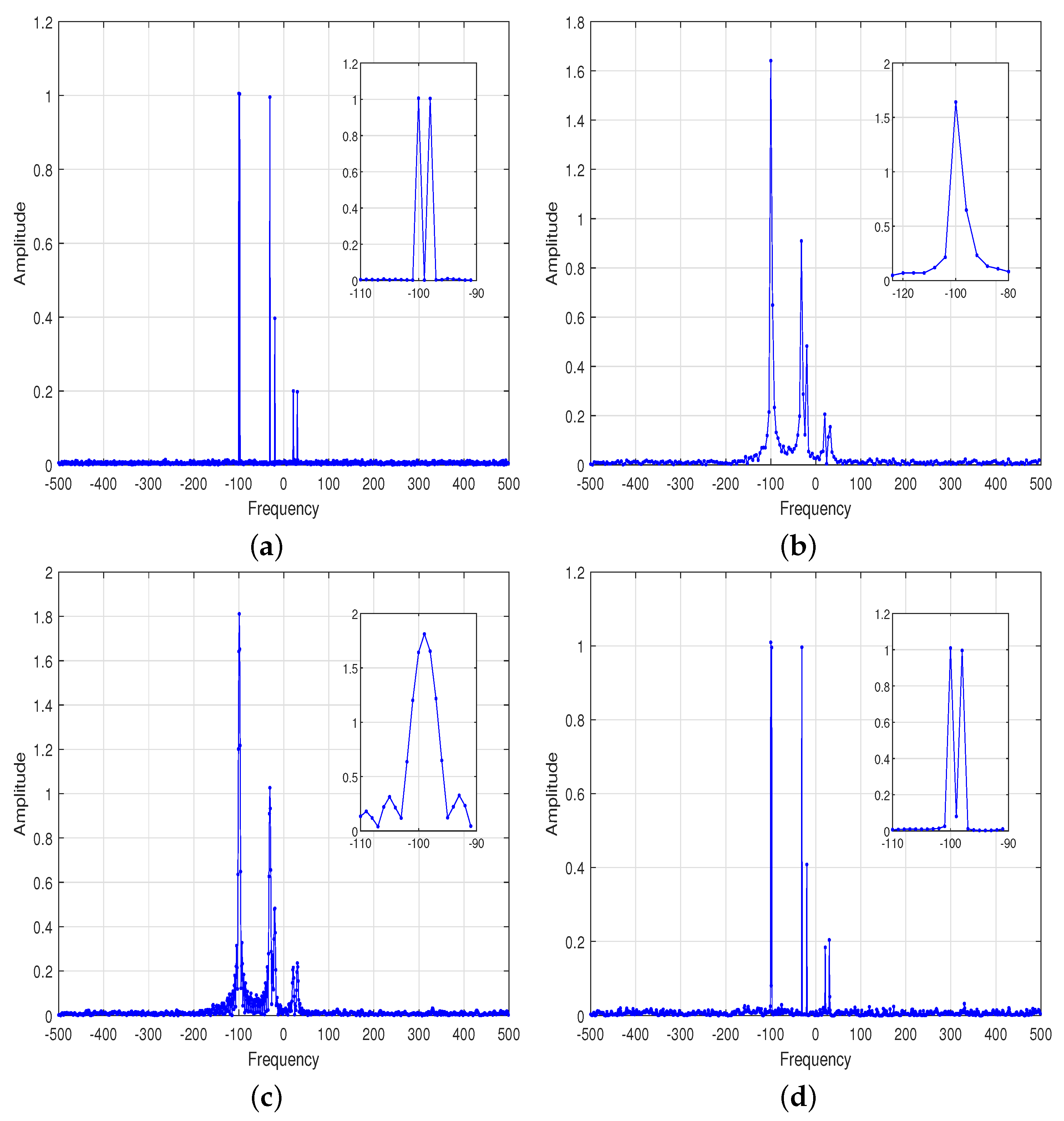
Since the time selection in the azimuth direction leads to a reduction in azimuth resolution, the spectrum estimation is only carried out in the azimuth direction range cell by range cell, which allows us to simulate a one-dimensional (1-D) signal to illustrate the problem. Assuming that the sampling rate of the signal is 1000 Hz and the number of samples is 1000, thus the frequency resolution is 1 Hz. Six typical targets numbered 1–6 are considered in the simulation, and the corresponding frequencies are , , , , 21, 30, the corresponding amplitudes are 1, 1, 1, 0.4, 0.2, 0.2. Different targets are for different purposes, target 1 and target 2 represent targets with the same amplitude and adjacent frequency, target 3 and target 4 represent targets with adjacent frequency and large amplitude difference, target 5 and target 6 represent targets with low power, the signal noise obeys complex Gaussian distribution, and the signal-to-noise ratio (SNR) is set to 20 dB. Because of the high frequency resolution, the fast Fourier transform (FFT) can be used for spectrum estimation as shown in Figure 4a. Then the signal is truncated, and only 250 samples in the middle of the signal are selected, thus the frequency resolution is 4 Hz by theoretical calculation. As shown in Figure 4b, the frequencies of target 1 and target 2 are difficult to distinguish by FFT, meanwhile, the amplitude estimation error is large. With the zero padding FFT, the target 1 and target 2 are still difficult to distinguish in Figure 4c. IAA is used for spectrum estimation in Figure 4d, the frequencies of target 1 and target 2 are separated, and the amplitude estimation error is acceptable.
4.2. Moving Ship Simulation Experiment
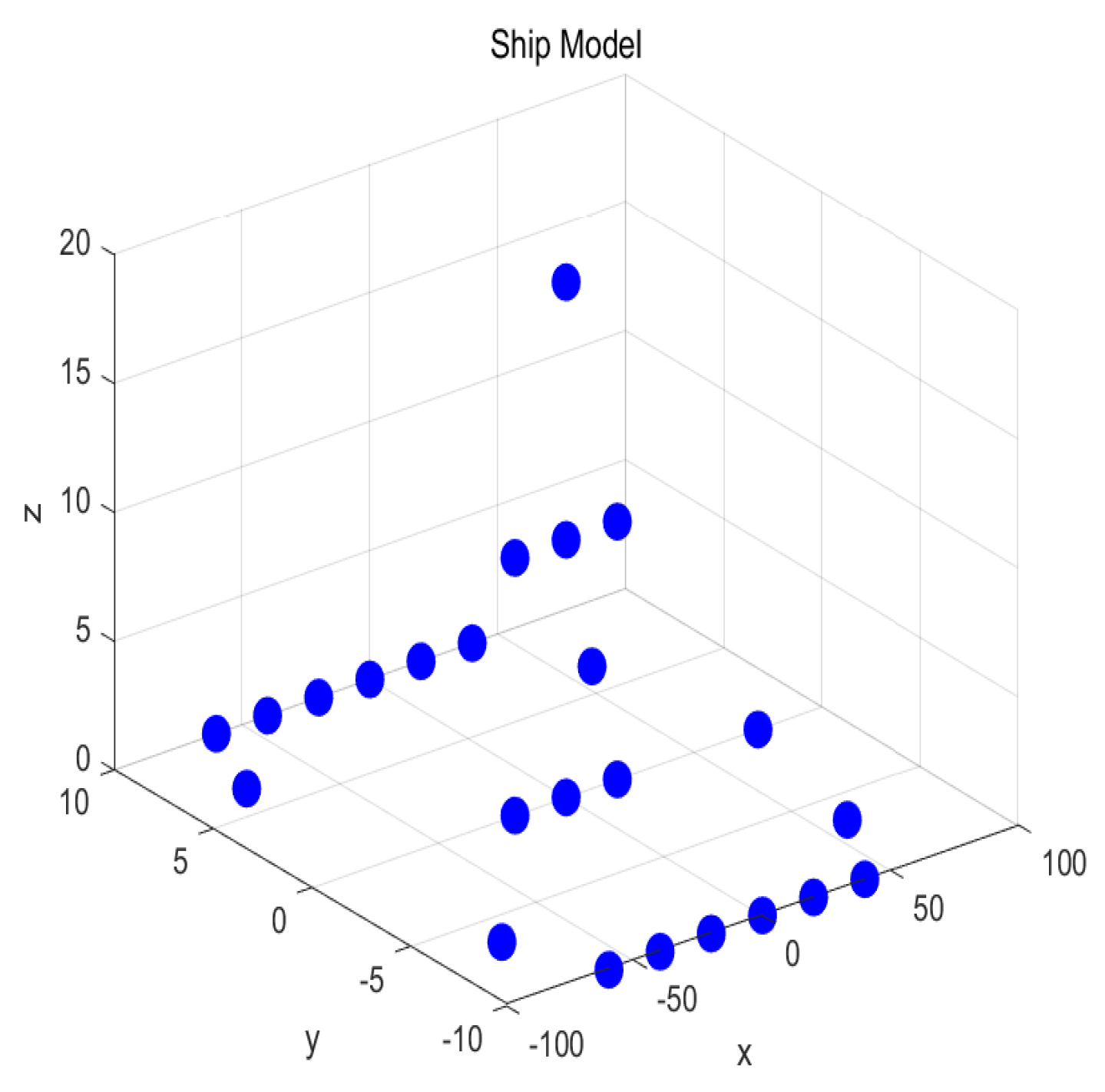
In order to verify the focusing performance of the proposed method on the defocused ship in the SAR image, two simulation experiments are carried out in the subsection. The simulation model is shown in Figure 5 and the system parameters of the radar platform are shown in Table 1.
In the first simulation experiment, a navigating ship with 2-D (range and azimuth) velocities is studied. The angle between the ship orientation and the X axis is 45, the velocity of the ship is set to 5 m/s, and the 3-D (roll, pitch, and yaw) rotational velocities of the ship are set to 0.
Figure 6a shows the defocusing phenomenon caused by the sailing velocity of the ship. Then, SAR subimage is first transformed into the ISAR echo domain through the inverse mapping, and the motion compensation method is carried out. Figure 6b shows the RD imaging result after motion compensation. The ship target is focused after motion compensation, and the image quality is improved, which indicates the effectiveness of the motion compensation method.
However, some ships on the sea will produce 3-D rotational motions due to the sea waves and other factors. In this case, the Doppler frequency of the scatterer on the ship after motion compensation is not constant, and it varies with the change of azimuth time. Since each scatterer on the ship has different time-varying Doppler frequency, it is difficult to image all the ship scatterers.
After motion compensation, the echo data in a short imaging time is selected for ISAR imaging based on the maximum image contrast search method. Since the Doppler frequency in the selected imaging time is assumed to be approximately constant, the IAA is used to achieve ISAR super-resolution imaging.
In the second simulation experiment, a navigating ship with the same velocity and orientation as the first simulation experiment is studied, meanwhile 3-D rotational motions are added, and the parameters of rotational motions are shown in Table 2.
Figure 7a shows a SAR subimage that contains a defocused ship. Due to the translational motion and 3-D rotational motions of the ship, the SAR image of the ship is severely defocused, and the scatterers on the ship are difficult to identify. The image after motion compensation is shown in Figure 7b, the imaging performance is improved, but the ship scatterers still have severe defocusing phenomenon after motion compensation. The reason for this phenomenon is that even if translational motion compensation is performed, the Doppler frequency of the scatterer caused by the 3-D rotational motions is still changing. After optimal imaging time selection, the Doppler frequency of the ship is approximately constant within the selected imaging time and the RD imaging result is shown in Figure 7c, the azimuth resolution is low. IAA imaging result is shown in Figure 7d, the image quality is improved, and the azimuth resolution is improved.
4.3. Real Data of Gaofen-3
Because the stripmap mode of Gaofen-3 has short illuminated time and low resolution, in this subsection, Gaofen-3 sliding spotlight SAR data are used to verify the effectiveness of the proposed method. Some system parameters of Gaofen-3 sliding spotlight mode are shown in Table 3. The resolution of this mode can reach to 1 m [41], and the defocusing phenomenon of the moving ship is apparent in the SAR image, which seriously affects the applications of SAR image, such as ship classification and identification. Because the general SAR processing flow for the sliding spotlight mode of Gaofen-3 is complicated, and the energy spread across the range cells is not obvious for Gaofen-3 data. Therefore, this paper directly performs range alignment in the ISAR equivalent echo domain by minimizing the entropy of the ARP [34].
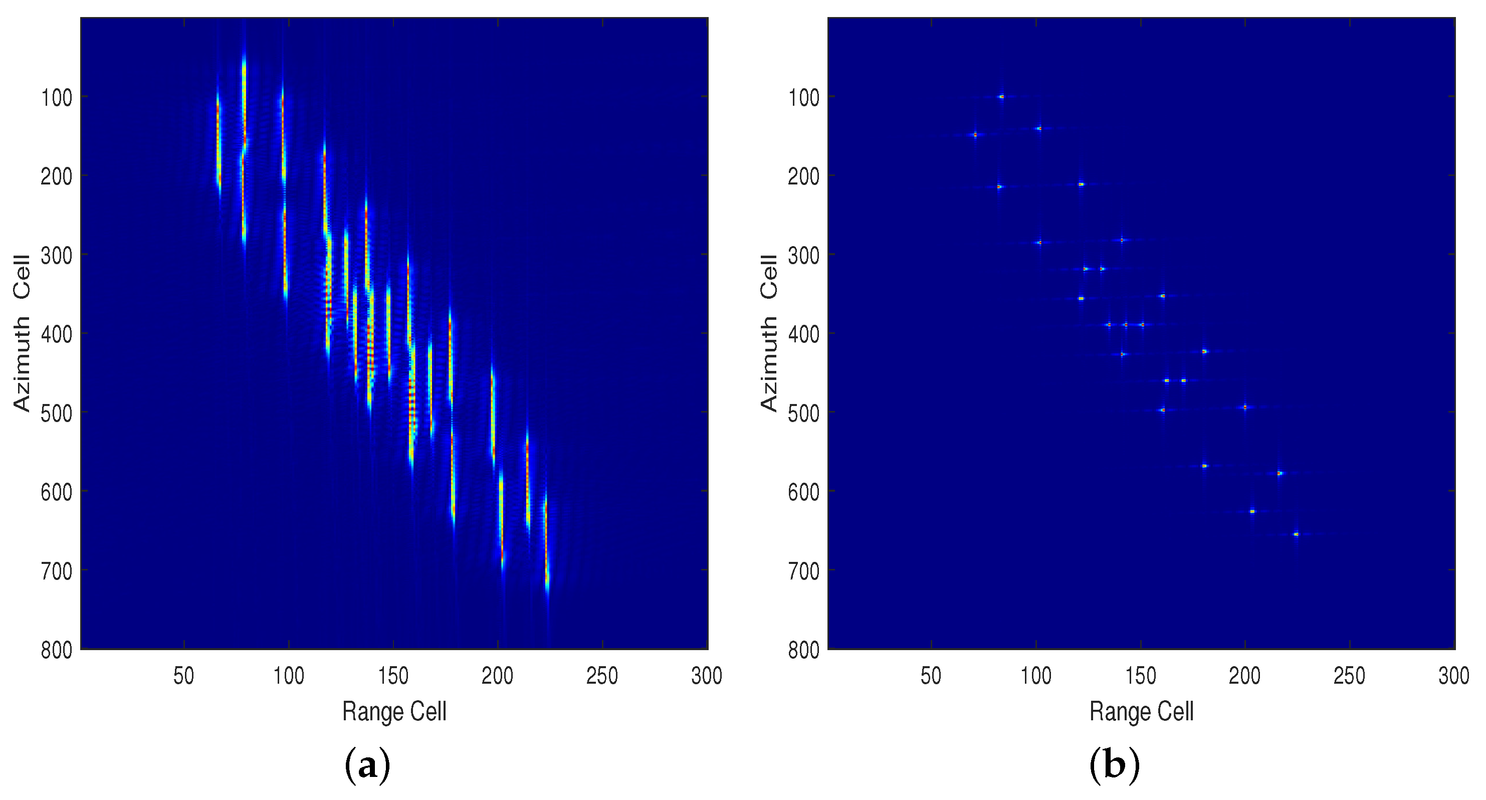
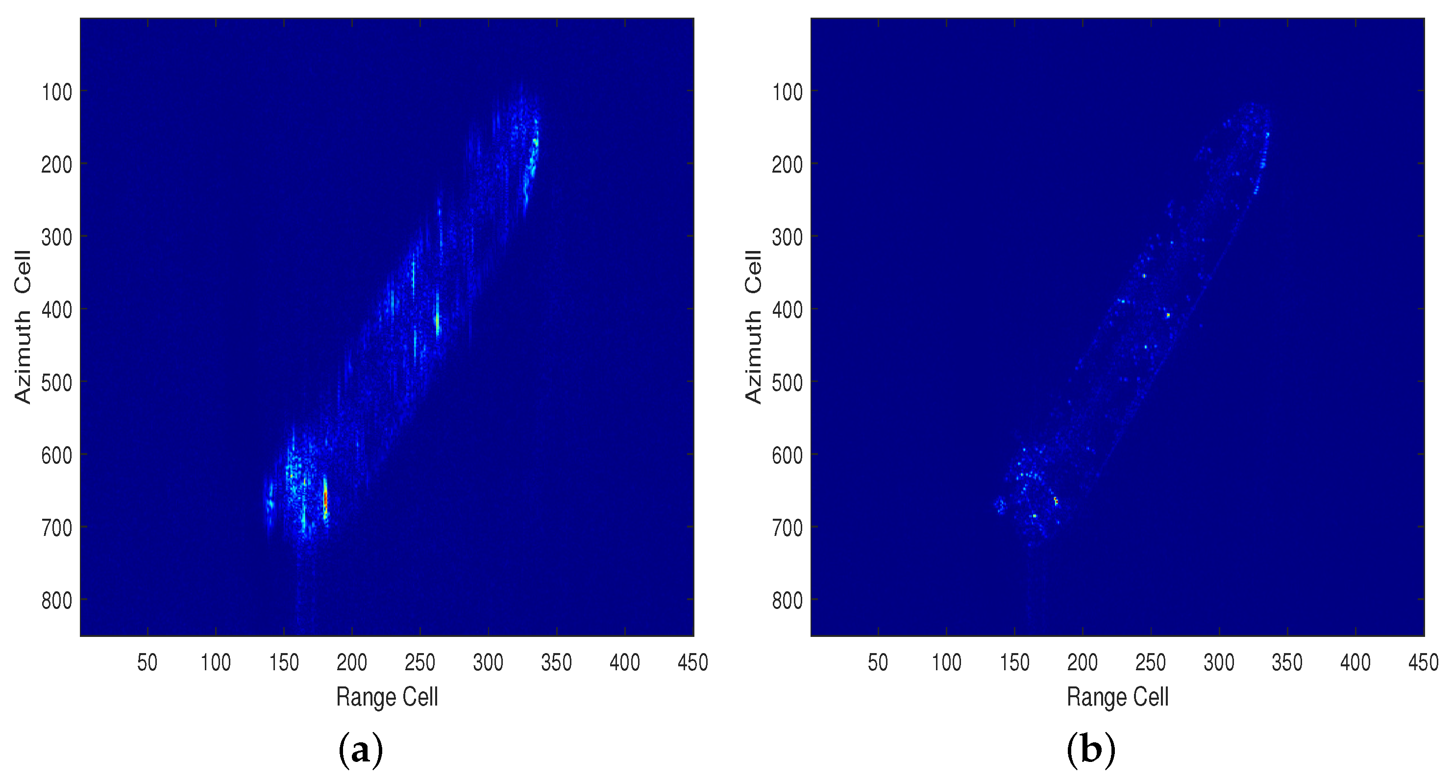
In the first SAR subimage, a navigating ship is used to verify the motion compensation method. The 3-D rotational motions of the ship can be neglected in this subimage. The SAR ship subimage is shown in Figure 8a, the ship appears defocused in the subimage, which is mainly caused by the 2-D sailing velocities. The motion compensation result is shown in Figure 8b, the ship is well focused after motion compensation through RD imaging method, this result verifies the effectiveness of the motion compensation method.
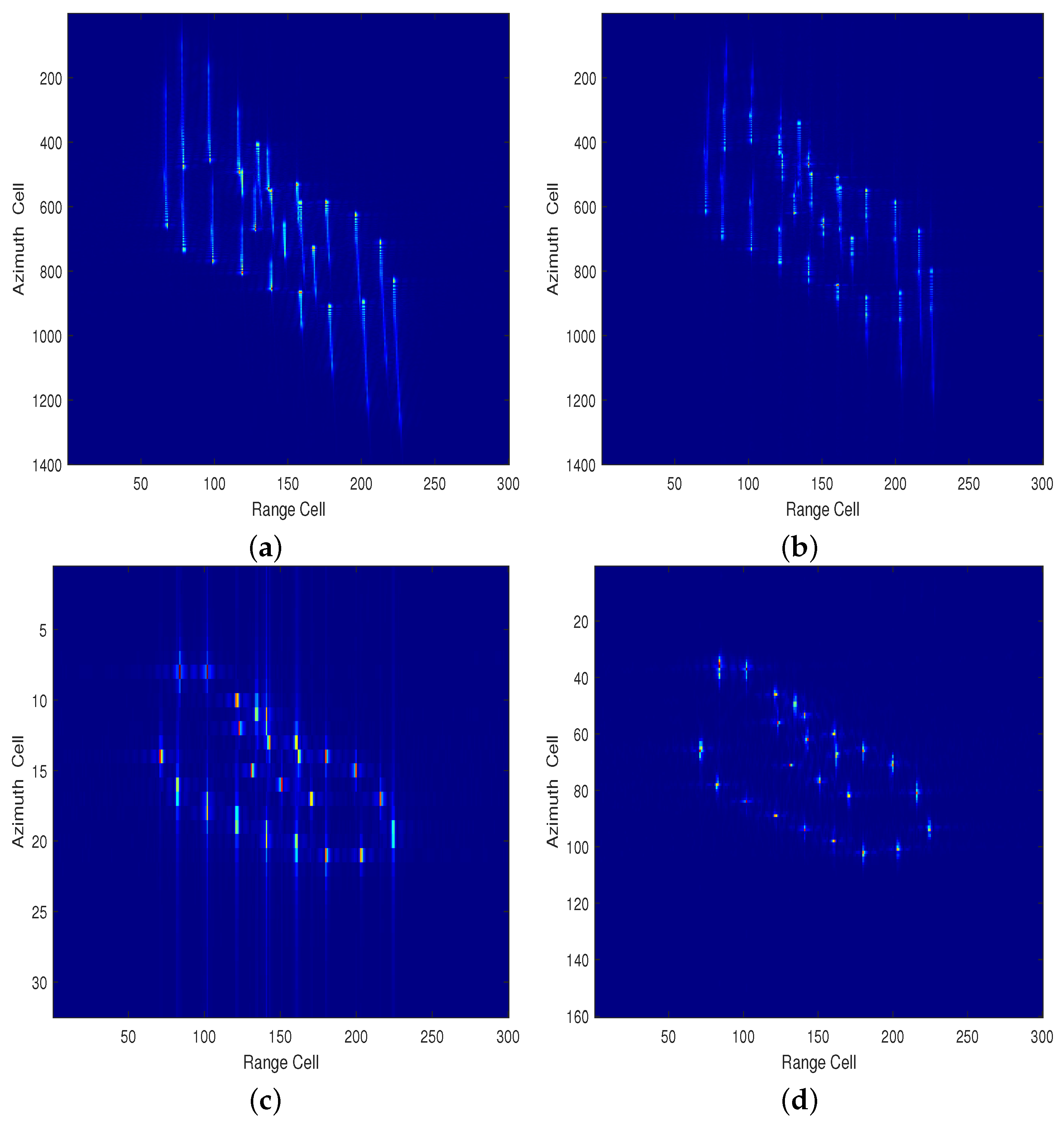
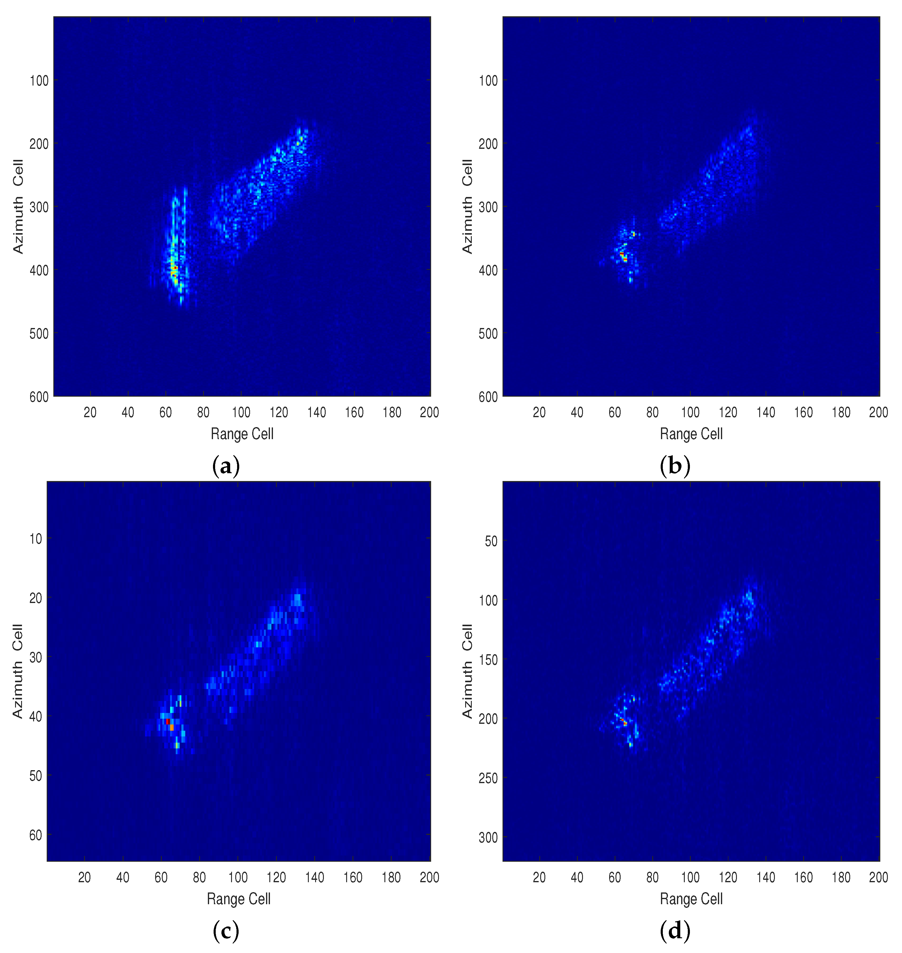
In order to verify the effectiveness of the proposed method, two navigating ships with 3-D rotational motions named rotating ship 1 and rotating ship 2 are used. For the rotating ship 1, the defocused SAR subimage is shown in Figure 9a. The motion compensation result is shown in Figure 9b, the ship still appears defocused due to the rotational motions introduced by sea waves and other factors, and the bow and stern cannot be focused at the same time. Figure 9c shows the ship image after optimal imaging time selection through the maximum image contrast search method, the resolution is reduced after time selection, which is the same as the STFT in [26], however, the Doppler frequency is almost constant in the imaging time period, which allows us to obtain ship image through super-resolution spectral estimation. Finally, IAA is used to obtain the ship image range cell by range cell, and the final ship image is shown in Figure 9d.
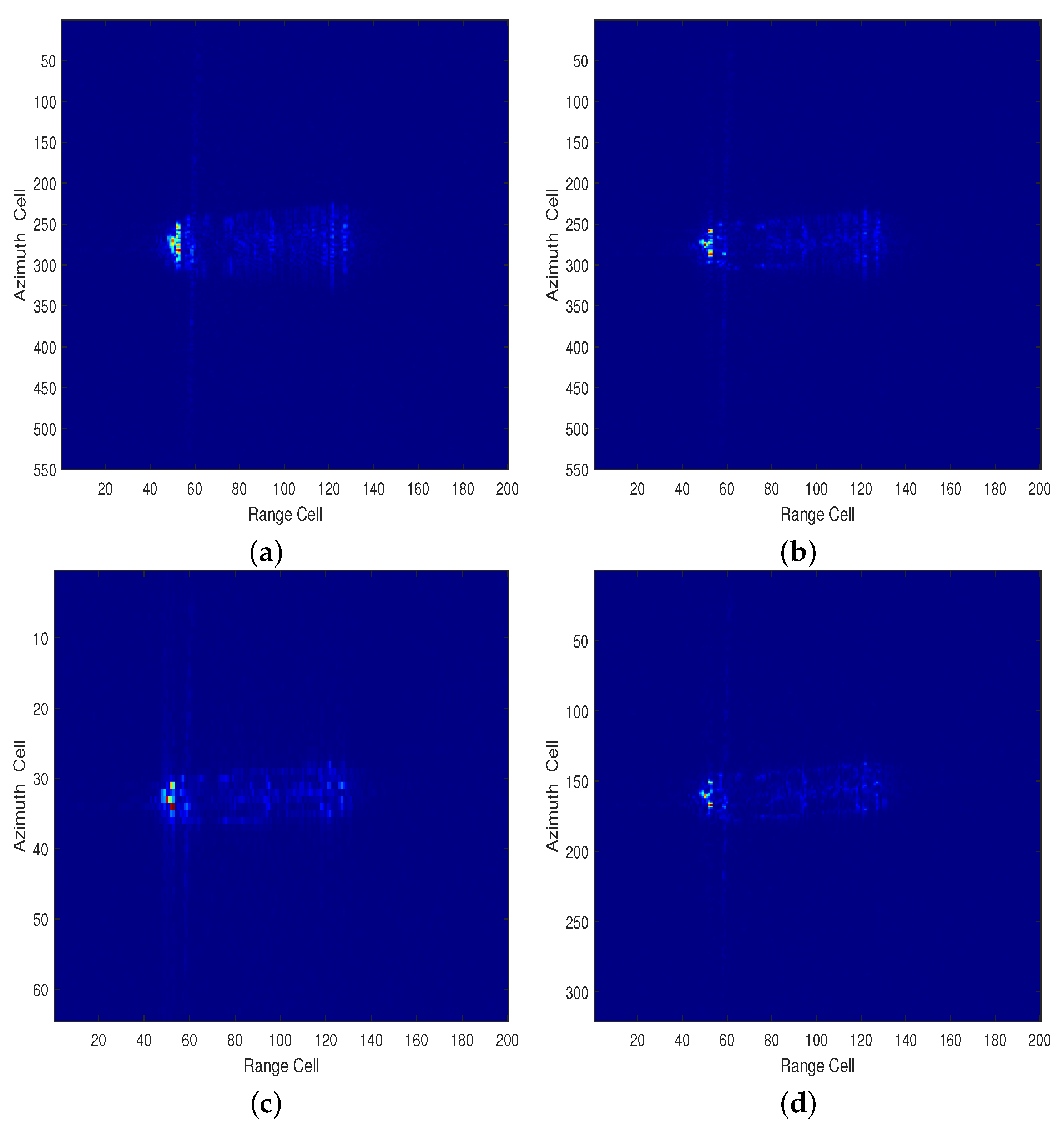
As shown in Figure 10a, the rotating ship 2 suffers from image distortion due to the velocity and 3-D rotational motions, the processing flow is the same as the rotating ship 1, the image after motion compensation is shown in Figure 10b, the ship still appears defocused, especially the stern, the optimal imaging time selection result is shown in Figure 10c, the result of IAA is shown in Figure 10d, the image quality is improved after the processing, which shows the effectiveness of the proposed imaging method.
5. Discussion
In this paper, the refocusing method of the navigating ship with 3-D rotational motions is studied. Due to the advantages of ISAR technique in non-cooperative target imaging, the ISAR equivalent echo is obtained from SAR subimage which contains a single defocused ship. Then motion compensation including range alignment and phase compensation is carried out to compensate the identical movement of all ship scatterers, the moving ship whose 3-D rotational motions can be neglected will form a well focused image through RD imaging method, as shown in Figure 6, the simulation ship is well focused after motion compensation via RD imaging, moreover, the motion compensation performance is also verified by the real SAR data of the Gaofen-3 in Figure 8. Both simulated data and real SAR data have a good focus effect and high resolution.
However, many ships with 3-D rotational motions will have time-varying Doppler frequency after motion compensation, which will affect the RD imaging result. For simulation ship in Figure 7, the ship still suffers from defocusing after motion compensation, a short imaging time is selected by the maximum image contrast search method, and the RD imaging result is shown in Figure 7c, the motion during the selected imaging time is considered as smooth, thus the Doppler frequency variation is not obvious, the time selection method has the similar principle as STFT, and shorter imaging time will bring worse azimuth resolution since the look angle variation is small. To improve the resolution, the IAA is used to achieve the azimuth imaging, as shown in Figure 7d, the azimuth resolution has been improved after IAA imaging. The contradiction between time resolution and frequency resolution is alleviated, thus the proposed method has satisfactory imaging performance in both azimuth resolution and image focus. The high-resolution SAR data of Gaofen-3 is also used to verify the proposed method in Figure 9 and Figure 10, the proposed method shows good imaging performance for ships with 3-D rotational motions. In the future, optimal imaging time selection algorithm will be further researched to select the smooth motion time accurately and fast with ISAR equivalent echo.
6. Conclusions
A novel method for refocusing moving ships in SAR images is proposed in this paper. Both the 2-D velocities and 3-D rotational motions of the moving ship are considered. Through the motion compensation in the ISAR equivalent echo domain obtained from the SAR subimage, the identical motion of all the scatterers on the ship can be compensated. Furthermore, the optimal imaging time is selected through the maximum image contrast search method. Finally the image is obtained through IAA with high resolution and low side lobes. The proposed method has good focusing performance for moving ships in both azimuth resolution and image focus, and the whole processing flow is based on SAR subimages, which has a small amount of calculation and great convenience.
Author Contributions
Conceptualization, X.J. and H.S.; methodology, X.J.; software, X.J.; validation, X.J.; formal analysis, X.J.; investigation, X.J. and W.H.; resources, H.S.; data curation, H.S.; writing—original draft preparation, X.J.; writing—review and editing, X.J.; visualization, X.J.; supervision, H.S.; project administration, H.S.; funding acquisition, H.S. All authors have read and agreed to the published version of the manuscript.
Funding
This research was funded by the National Key Research and Development Program of China under Grant 2017YFB0502700.
Institutional Review Board Statement
Not applicable.
Informed Consent Statement
Not applicable.
Data Availability Statement
Restrictions apply to the availability of these data. Data was obtained from National Satellite Ocean Application Service and are available at https://osdds.nsoas.org.cn with the permission of National Satellite Ocean Application Service.
Conflicts of Interest
The authors declare no conflict of interest.
References
- Raney, R. Synthetic Aperture Imaging Radar and Moving Targets. IEEE Trans. Aerosp. Electron. Syst. 1971, AES-7, 499–505. [Google Scholar] [CrossRef]
- Pelich, R.; Longépé, N.; Mercier, G.; Hajduch, G.; Garello, R. Vessel Refocusing and Velocity Estimation on SAR Imagery Using the Fractional Fourier Transform. IEEE Trans. Geosci. Remote Sens. 2016, 54, 1670–1684. [Google Scholar] [CrossRef]
- Zhang, Y.; Sun, J.; Lei, P.; Li, G.; Hong, W. High-Resolution SAR-Based Ground Moving Target Imaging With Defocused ROI Data. IEEE Trans. Geosci. Remote Sens. 2016, 54, 1062–1073. [Google Scholar] [CrossRef]
- Chen, Y.; Li, G.; Zhang, Q.; Sun, J. Refocusing of Moving Targets in SAR Images via Parametric Sparse Representation. Remote Sens. 2017, 9, 795. [Google Scholar] [CrossRef] [Green Version]
- Noviello, C.; Fornaro, G.; Martorella, M. Focused SAR Image Formation of Moving Targets Based on Doppler Parameter Estimation. IEEE Trans. Geosci. Remote Sens. 2015, 53, 3460–3470. [Google Scholar] [CrossRef]
- Huang, X.; Ji, K.; Leng, X.; Dong, G.; Xing, X. Refocusing Moving Ship Targets in SAR Images Based on Fast Minimum Entropy Phase Compensation. Sensors 2019, 19, 1154. [Google Scholar] [CrossRef] [PubMed] [Green Version]
- Chen, V.; Lipps, R. ISAR Imaging of Small Craft with Roll, Pitch and Yaw Analysis. In Proceedings of the Record of the IEEE 2000 International Radar Conference [Cat. No. 00CH37037], Alexandria, VA, USA, 12 May 2000; pp. 493–498. [Google Scholar] [CrossRef]
- Liu, P.; Jin, Y.Q. A Study of Ship Rotation Effects on SAR Image. IEEE Trans. Geosci. Remote Sens. 2017, 55, 3132–3144. [Google Scholar] [CrossRef]
- Zhou, B.; Qi, X.; Zhang, J.; Zhang, H. Effect of 6-DOF Oscillation of Ship Target on SAR Imaging. Remote Sens. 2021, 13, 1821. [Google Scholar] [CrossRef]
- Xiong, W.; Zhang, Y.; Dong, X.; Cui, C.; Liu, Z.; Xiong, M. A Novel Ship Imaging Method with Multiple Sinusoidal Functions to Match Rotation Effects in Geosynchronous SAR. Remote Sens. 2020, 12, 2249. [Google Scholar] [CrossRef]
- Martorella, M.; Berizzi, F. Time Windowing for Highly Focused ISAR Image Reconstruction. IEEE Trans. Aerosp. Electron. Syst. 2005, 41, 992–1007. [Google Scholar] [CrossRef]
- Martorella, M.; Berizzi, F.; Haywood, B. Contrast Maximisation Based Technique for 2-D ISAR Autofocusing. IEE Proc. Radar Sonar Navig. 2005, 152, 253. [Google Scholar] [CrossRef] [Green Version]
- Martorella, M.; Giusti, E.; Berizzi, F.; Bacci, A.; Dalle Mese, E. ISAR Based Technique for Refocusing Non-Cooperative Targets in SAR Images. IET Radar Sonar Navig. 2012, 6, 332. [Google Scholar] [CrossRef]
- Chen, Y.; Zhou, P.; Dai, Y. Application of an Existing Approach to Refocusing Maritime Moving Targets on Radarsat-2 SLC Images. In Proceedings of the 2015 IEEE 5th Asia-Pacific Conference on Synthetic Aperture Radar (APSAR), Singapore, 1–4 September 2015; pp. 502–506. [Google Scholar] [CrossRef]
- Shao, S.; Zhang, L.; Liu, H. An Optimal Imaging Time Interval Selection Technique for Marine Targets ISAR Imaging Based on Sea Dynamic Prior Information. IEEE Sens. J. 2019, 19, 4940–4953. [Google Scholar] [CrossRef]
- Gaffar, M.; Nel, W.; Inggs, M. Selecting Suitable Coherent Processing Time Window Lengths for Ground-Based ISAR Imaging of Cooperative Sea Vessels. IEEE Trans. Geosci. Remote Sens. 2009, 47, 3231–3240. [Google Scholar] [CrossRef]
- Zhang, Y.; Yan, S.; Tang, Z.; Yuan, B. Research on High-Resolution Ship Targets Radar Imaging at Sea. In Proceedings of the 2007 1st Asian and Pacific Conference on Synthetic Aperture Radar, Huangshan, China, 5–9 November 2007; pp. 536–540. [Google Scholar] [CrossRef]
- Kang, B.S.; Ryu, B.H.; Kim, C.H.; Kim, K.T. Improved Frame-Selection Scheme for ISAR Imaging of Targets in Complex 3-D Motion. IEEE Sens. J. 2018, 18, 111–121. [Google Scholar] [CrossRef]
- Zhang, S.; Liu, Y.; Li, X. Bayesian Bistatic ISAR Imaging for Targets With Complex Motion Under Low SNR Condition. IEEE Trans. Image Process. 2018, 27, 2447–2460. [Google Scholar] [CrossRef]
- Rihaczek, A.W.; Hershkowitz, S.J. Choosing imaging intervals for small ships. In Radar Processing, Technology, and Applications IV; Miceli, W.J., Ed.; International Society for Optics and Photonics, SPIE: Bellingham, WA, USA, 1999; Volume 3810, pp. 139–148. [Google Scholar] [CrossRef]
- Pastina, D.; Spina, C. Slope-Based Frame Selection and Scaling Technique for Ship ISAR Imaging. IET Signal Process. 2008, 2, 265. [Google Scholar] [CrossRef]
- Li, N.; Wang, L.; Zhu, D. Optimal ISAR Imaging Time Selection of Ship Targets Using Real Data. In Proceedings of the IET International Radar Conference 2013, Xi’an, China, 14–16 April 2013; pp. 1–4. [Google Scholar] [CrossRef]
- Xiang, T.; Wang, L.; Cao, Z.; Zhu, D. Doppler-Estimation Based Methods for Airborne ISAR Imaging of Non-Cooperative Ship Targets: Demonstration and Analysis. In Proceedings of the 2017 18th International Radar Symposium (IRS), Prague, Czech Republic, 28–30 June 2017; pp. 1–10. [Google Scholar] [CrossRef]
- Ding, Z.; Zhang, T.; Li, Y.; Li, G.; Dong, X.; Zeng, T.; Ke, M. A Ship ISAR Imaging Algorithm Based on Generalized Radon-Fourier Transform With Low SNR. IEEE Trans. Geosci. Remote Sens. 2019, 57, 6385–6396. [Google Scholar] [CrossRef]
- Yang, Z.; Li, D.; Tan, X.; Liu, H.; Liu, Y.; Liao, G. ISAR Imaging for Maneuvering Targets with Complex Motion Based on Generalized Radon-Fourier Transform and Gradient-Based Descent under Low SNR. Remote Sens. 2021, 13, 2198. [Google Scholar] [CrossRef]
- Chen, V.; Qian, S. Joint Time-Frequency Transform for Radar Range-Doppler Imaging. IEEE Trans. Aerosp. Electron. Syst. 1998, 34, 486–499. [Google Scholar] [CrossRef]
- Xu, X.; Su, F.; Gao, J.; Jin, X. High-Squint SAR Imaging of Maritime Ship Targets. IEEE Trans. Geosci. Remote Sens. 2020, 1–16. [Google Scholar] [CrossRef]
- Wang, Y.; Jiang, Y. ISAR Imaging of a Ship Target Using Product High-Order Matched-Phase Transform. IEEE Geosci. Remote Sens. Lett. 2009, 6, 658–661. [Google Scholar] [CrossRef]
- Li, D.; Gui, X.; Liu, H.; Su, J.; Xiong, H. An ISAR Imaging Algorithm for Maneuvering Targets with Low SNR Based on Parameter Estimation of Multicomponent Quadratic FM Signals and Nonuniform FFT. IEEE J. Sel. Top. Appl. Earth Obs. Remote Sens. 2016, 9, 5688–5702. [Google Scholar] [CrossRef]
- Pan, Z.; Fan, H.; Zhang, Z. Nonuniformly-Rotating Ship Refocusing in SAR Imagery Based on the Bilinear Extended Fractional Fourier Transform. Sensors 2020, 20, 550. [Google Scholar] [CrossRef] [Green Version]
- Cao, R.; Wang, Y.; Zhao, B.; Lu, X. Ship Target Imaging in Airborne SAR System Based on Automatic Image Segmentation and ISAR Technique. IEEE J. Sel. Top. Appl. Earth Obs. Remote Sens. 2021, 14, 1985–2000. [Google Scholar] [CrossRef]
- Qi, L.; Zheng, M.; Yu, W.; Li, N.; Hou, L. Super-Resolution Doppler Beam Sharpening Imaging Based on an Iterative Adaptive Approach. Remote Sens. Lett. 2016, 7, 259–268. [Google Scholar] [CrossRef]
- Liu, Y.; Wang, L.; Bi, G.; Liu, H.; Bi, H. Novel ISAR Range Alignment via Minimizing the Entropy of the Sum Range Profile. In Proceedings of the 2020 21st International Radar Symposium (IRS), Warsaw, Poland, 5–8 October 2020; IEEE: Warsaw, Pakistan, 2020; pp. 135–138. [Google Scholar] [CrossRef]
- Zhu, D.; Wang, L.; Yu, Y.; Tao, Q.; Zhu, Z. Robust ISAR Range Alignment via Minimizing the Entropy of the Average Range Profile. IEEE Geosci. Remote Sens. Lett. 2009, 6, 204–208. [Google Scholar] [CrossRef]
- Zhu, Z.; Qiu, X.; She, Z. ISAR motion compensation using modified Doppler centroid tracking method. In Proceedings of the IEEE 1996 National Aerospace and Electronics Conference NAECON 1996, Dayton, OH, USA, 20–22 May 1996; Volume 1, pp. 359–363. [Google Scholar] [CrossRef]
- Wahl, D.; Eichel, P.; Ghiglia, D.; Jakowatz, C. Phase gradient autofocus-a robust tool for high resolution SAR phase correction. IEEE Trans. Aerosp. Electron. Syst. 1994, 30, 827–835. [Google Scholar] [CrossRef] [Green Version]
- Wang, J.; Liu, X.; Zhou, Z. Minimum-Entropy Phase Adjustment for ISAR. IEE Proc. Radar Sonar Navig. 2004, 151, 203. [Google Scholar] [CrossRef]
- Berizzi, F.; Corsini, G. Autofocusing of Inverse Synthetic Aperture Radar Images Using Contrast Optimization. IEEE Trans. Aerosp. Electron. Syst. 1996, 32, 1185–1191. [Google Scholar] [CrossRef]
- Yardibi, T.; Li, J.; Stoica, P.; Xue, M.; Baggeroer, A.B. Source Localization and Sensing: A Nonparametric Iterative Adaptive Approach Based on Weighted Least Squares. IEEE Trans. Aerosp. Electron. Syst. 2010, 46, 425–443. [Google Scholar] [CrossRef]
- Roberts, W.; Stoica, P.; Li, J.; Yardibi, T.; Sadjadi, F.A. Iterative Adaptive Approaches to MIMO Radar Imaging. IEEE J. Sel. Top. Signal Process. 2010, 4, 5–20. [Google Scholar] [CrossRef]
- Han, B.; Ding, C.; Zhong, L.; Liu, J.; Qiu, X.; Hu, Y.; Lei, B. The GF-3 SAR Data Processor. Sensors 2018, 18, 835. [Google Scholar] [CrossRef] [Green Version]
Figure 1.
(a) The geometric relationship between the radar and the ship target. (b) 3-D rotational motion model of the ship target.
Figure 1.
(a) The geometric relationship between the radar and the ship target. (b) 3-D rotational motion model of the ship target.

Figure 2.
The ISAR imaging geometry.

Figure 3.
The flowchart of the proposed method.

Figure 4.
The performance of spectra estimation. (a) FFT with long observation time. (b) FFT with short observation time. (c) zero padding FFT with short observation time. (d) IAA with short observation time.
Figure 4.
The performance of spectra estimation. (a) FFT with long observation time. (b) FFT with short observation time. (c) zero padding FFT with short observation time. (d) IAA with short observation time.

Figure 5.
Ship model.

Figure 6.
The performance of the motion compensation method on simulated data. (a) SAR subimage. (b) RD imaging after motion compensation.
Figure 6.
The performance of the motion compensation method on simulated data. (a) SAR subimage. (b) RD imaging after motion compensation.

Figure 7.
The performance of the proposed method on simulated data. (a) SAR subimage (b) RD imaging after motion compensation. (c) RD imaging after optimal imaging time selection. (d) IAA imaging after optimal imaging time selection.
Figure 7.
The performance of the proposed method on simulated data. (a) SAR subimage (b) RD imaging after motion compensation. (c) RD imaging after optimal imaging time selection. (d) IAA imaging after optimal imaging time selection.

Figure 8.
The performance of the motion compensation method on Gaofen-3 data. (a) SAR subimage. (b) RD imaging after motion compensation.
Figure 8.
The performance of the motion compensation method on Gaofen-3 data. (a) SAR subimage. (b) RD imaging after motion compensation.

Figure 9.
The performance of the proposed method on rotating ship 1. (a) SAR subimage. (b) RD imaging after motion compensation. (c) RD imaging after optimal imaging time selection. (d) IAA imaging after optimal imaging time selection.
Figure 9.
The performance of the proposed method on rotating ship 1. (a) SAR subimage. (b) RD imaging after motion compensation. (c) RD imaging after optimal imaging time selection. (d) IAA imaging after optimal imaging time selection.

Figure 10.
The performance of the proposed method on rotating ship 2. (a) SAR subimage. (b) RD imaging after motion compensation. (c) RD imaging after optimal imaging time selection. (d) IAA imaging after optimal imaging time selection.
Figure 10.
The performance of the proposed method on rotating ship 2. (a) SAR subimage. (b) RD imaging after motion compensation. (c) RD imaging after optimal imaging time selection. (d) IAA imaging after optimal imaging time selection.


Table 1.
The system parameters of the simulation experiment.
| Parameter | Value |
|---|---|
| Carrier frequency (GHz) | 5.4 |
| Platform velocity (m/s) | 150 |
| Slant range of scene center (Km) | 10 |
| A/D sampling rate (MHz) | 240 |
| Squint angle () | 0 |
| Bandwidth (MHz) | 200 |
| Pulse width (s) | 1 |
| Pulse repetition frequency (Hz) | 750 |
Table 2.
The parameters of rotational motions.
| Rotational Mode | Amplitude (°) | Period (s) | Central Time Phase (°) |
|---|---|---|---|
| Roll | 5 | 12.2 | 0 |
| Pitch | 1.7 | 6.7 | 0 |
| Yaw | 1.9 | 14.2 | 0 |
Table 3.
The system parameters of Gaofen-3.
| Parameter | Value |
|---|---|
| Carrier frequency (GHz) | 5.4 |
| Platform velocity (m/s) | 7571 |
| Slant range of scene center (Km) | 856.33 |
| A/D sampling rate (MHz) | 266.67 |
| Bandwidth (MHz) | 240 |
| Pulse width (s) | 45 |
| Pulse repetition frequency (Hz) | 3591 |
Publisher’s Note: MDPI stays neutral with regard to jurisdictional claims in published maps and institutional affiliations. |
© 2021 by the authors. Licensee MDPI, Basel, Switzerland. This article is an open access article distributed under the terms and conditions of the Creative Commons Attribution (CC BY) license (https://creativecommons.org/licenses/by/4.0/).
Share and Cite
MDPI and ACS Style
Jia, X.; Song, H.; He, W. A Novel Method for Refocusing Moving Ships in SAR Images via ISAR Technique. Remote Sens. 2021, 13, 2738. https://0-doi-org.brum.beds.ac.uk/10.3390/rs13142738
AMA Style
Jia X, Song H, He W. A Novel Method for Refocusing Moving Ships in SAR Images via ISAR Technique. Remote Sensing. 2021; 13(14):2738. https://0-doi-org.brum.beds.ac.uk/10.3390/rs13142738
Chicago/Turabian StyleJia, Xinlin, Hongjun Song, and Wenjing He. 2021. "A Novel Method for Refocusing Moving Ships in SAR Images via ISAR Technique" Remote Sensing 13, no. 14: 2738. https://0-doi-org.brum.beds.ac.uk/10.3390/rs13142738
Note that from the first issue of 2016, this journal uses article numbers instead of page numbers. See further details here.