Article

Improved Single-Frequency Kinematic Orbit Determination Strategy of Small LEO Satellite with the Sun-Pointing Attitude Mode

State Key Laboratory of Information Engineering in Surveying, Mapping and Remote Sensing, Wuhan University, Wuhan 430079, China
*
Author to whom correspondence should be addressed.
Remote Sens. 2021, 13(19), 4020; https://0-doi-org.brum.beds.ac.uk/10.3390/rs13194020
Submission received: 27 August 2021 / Revised: 22 September 2021 / Accepted: 6 October 2021 / Published: 8 October 2021
(This article belongs to the Special Issue Autonomous Space Navigation)

Abstract

:
Kinematic orbit determination (KOD) of low earth orbit (LEO) satellites only using single-frequency global navigation satellite system (GNSS) data is a suitable solution for space applications demanding meter-level orbit precision. For some small LEO satellites with the sun-pointing attitude mode, the rotation of the GNSS antenna radiation pattern changes the observation noise characteristics. Since the rotation angle information of the antenna plane may not be available for most low-cost missions, the true elevation cannot be computed and a general elevation-dependent weighting model remains invalid for the onboard GNSS observations. Furthermore, the low-stability GNSS receiver clock oscillator of the LEO satellite at high speeds makes single-frequency cycle slip detection ineffective and difficult since the clock steering events occur frequently. In this study, we investigated the improved KOD strategy to improve the performance of orbit solution using single-frequency GPS and BeiDou navigation satellite system (BDS) observations collected from the Luojia-1A satellite. The weighting model based on exponential function and signal strength is proposed according to the analysis of satellite attitude impact, and a joint single-frequency detection algorithm of receiver clock jump and cycle slip is investigated as well. Based on the GPS/BDS-combined KOD results, it is demonstrated that the clock jump and cycle slip can be properly detected and observations can be effectively utilized with the proposed weighting model considering satellite attitude, which significantly improves the availability and accuracy of orbit solution. The number of available epochs is increased by 12.9% benefitting from this strategy. The orbital root mean square (RMS) precision improvements in the radial, along-track, and cross-track directions are 22.1%, 16.4%, and 6.5%, respectively. Combining BDS observations also contributes to orbit precision improvement, which reaches up to 28.8%.

1. Introduction

Low earth orbit (LEO) satellites are usually equipped with a dual-frequency or single-frequency global navigation satellite system (GNSS) receiver for computing orbit. The GNSS-based orbit determination has been widely used for various LEO satellites, such as TOPEX/POSEIDON [1,2,3], CHAMP [4], Jason-1 [5], GRACE [6], Swarm [7], Sentinel [8], FengYun-3C [9], and so on. Precise orbit determination (POD) at centimeter-level accuracy can be achieved with dual-frequency observations by reduced dynamic filtering that exploits the unique geometric strength and considers the pseudo-stochastic orbit modeling techniques [10] or zero-difference kinematic precise point positioning (PPP) [11,12,13,14,15]. Some researchers have also worked toward the integrated adjustment of CHAMP, GRACE, and GPS data [16], enhancing the performance of POD with LEO onboard multiple GNSS data [17,18] and improving the robustness of the solution by piece-wisely linearly modeling the onboard GPS receiver oscillators [19].
Dual-frequency POD can obtain higher orbit accuracy than a single-frequency method through eliminating the first-order ionosphere effects, but needs an expensive geodetic GNSS receiver and complex computation algorithm. A small LEO satellite platform that has been popular in commercial aerospace applications controls costs strictly. Determining satellite orbit with a low-cost single-frequency receiver will be the primary option for future small LEO satellites since it not only saves cost, but also meets the accuracy requirement for real-time orbit [20]. Some low-cost single-frequency receivers have successfully implemented the real-time orbit determination of the LEO satellite for high dynamics applications, such as the miniature Phoenix-XNS GPS receiver [21,22], the single-frequency GPS receiver carried by the SJ-9A LEO satellite [23]. The methods for the reduced dynamic orbit generation or the kinematic orbit determination (KOD) with single-frequency data can achieve orbit accuracies of one meter or the sub-meter level, respectively, depending on the noise of code observations and the correction of ionospheric error [24,25]. The KOD can be applied for both free-flying and maneuvering spacecraft since it is free of any assumptions on the motion of LEO satellites. Therefore, the single-frequency KOD method is considered suitable for low-cost space applications demanding meter-level orbit precision.
However, there are still some challenges for LEO orbit determination in processing the impact of satellite attitude since some LEO satellites use the sun-pointing attitude mode rather than the earth-pointing attitude mode to obtain enough energy from the solar panel. The sun-pointing satellite attitude mode has a significant impact on computing elevation since the onboard GNSS antenna is fixed to the LEO satellite, and its motion around the earth produces a changing discrepancy that the antenna boresight direction is not in line with the up direction of the local Cartesian coordinate system, where the origin is the onboard GNSS receiver, and the up direction always points towards outer space. The rotation of the GNSS antenna radiation pattern changes the noise characteristics and the true elevation cannot be computed because there is no rotation angle information of the antenna plane for most low-cost LEO satellites. The negative elevations occur relative to the local horizontal plane, such as the CANX-2 mission [26], BIRD mission [27], PROBA-2 mission [28], etc. For these small satellite missions, a C/N0-based weighting strategy is more suitable than the elevation-dependent weighting function. Moreover, some low-cost onboard GNSS receivers equipped with low-stability oscillators cause the fast changes of the receiver bias. The receiver clock is frequently adjusted to maintain a controllable apparent clock bias. As a result, the receiver clock steering event occurs frequently, which is a big disadvantage for the single-frequency cycle slip detection. Considering these challenges, in this study, we propose a suitable weighting model and a joint detection of clock jump and cycle slip algorithms for the single-frequency GPS and BeiDou navigation satellite system (BDS)-combined KOD of LEO satellites using the sun-pointing attitude mode. Based on the careful analysis of the satellite attitude’s impact, a weighting model based on exponential function is extended for correctly processing the observations of low or negative elevations to improve the availability of the KOD solution. The proposed cycle slip algorithm can jointly process receiver clock discontinuity and cycle slip.
This paper is organized as follows. The GPS/BDS-combined KOD model is first introduced in Section 2, and then the impact of the LEO satellite attitude and the improved weighting model are discussed. The joint single-frequency receiver clock jump and cycle slip detection algorithm are also presented in Section 2. The improved single-frequency KOD strategy is validated on the Luojia-1A satellite, which is a scientific experimental low-cost small LEO satellite adopting the sun-pointing attitude mode. Section 3 first introduces Luojia-1A satellite information and a basic data processing configuration. The experiment validation results based on Luojia-1A onboard GPS/BDS data are then described and analyzed. The conclusions are given in Section 4.

2. Methodology

For single-frequency GNSS data processing, ionosphere delay is one of the most challenging issues. In this study, the group and phase ionospheric correction (GRAPHIC) model is used to eliminate the first-order ionospheric effects [29]. The GPS/BDS-combined single-frequency KOD model is first introduced, and then an improved data-processing strategy, including the adaption of the weighting model and the joint detection algorithm of receiver clock jump and cycle slip based on single-frequency observations, is described.

2.1. GPS/BDS-Combined Single-Frequency KOD Model

For the GPS/BDS-combined KOD model, the equation of single-frequency pseudorange and carrier phase observation from a satellite to the LEO onboard GPS/BDS receiver r is given as follows:
{ P r s = ρ r s + c ( t r t s ) + d r d s + I r s + ε p s L r s = ρ r s + c ( t r t s ) I r s + λ s ( B r s + b r b s ) + ε l s
where s represents the satellite of the GPS or the BDS system; respectively, P r s and L r s are the pseudorange and carrier phase observation in meters; ρ r s is the geometry distance between the satellite and receiver; c is the speed of light in a vacuum; t r is the receiver offset and t s is the satellite clock offset; d r is the receiver uncalibrated code delay (UCD) and d s is the satellite UCD; I r s is the ionospheric delay; B r s is the integer phase ambiguity in the unit of cycles and λ s is the wavelength; b r is the receiver uncalibrated phase delay (UPD) and b s is the satellite UPD; ε p s and ε l s are the multipath and measurement noises of the pseudorange and phase observation, respectively.
In this model, the tropospheric delay error does not exist, since most LEO satellite orbits operate on the top of the troposphere and the tropospheric impact on the GNSS signal is negligible. The inter-system bias between GPS and BDS can be treated as white noise; thus, the independent receiver clock parameter is set for the GPS or BDS system. The corresponding receiver UCD can be combined into the receiver clock since it is usually stable. For the ionosphere delay, there are many correction techniques, such as the NeQuick [30], the TIEGCM [31], the NTCM-GL [32], and the Klobuchar model [33], for single-frequency GNSS observation from a LEO satellite. A downscaled version of the Klobuchar model is used for convenience to mitigate the ionosphere effect in the pseudorange observation, and the scale factor is empirically given as 0.3 [34]. The pseudorange observation is then combined with phase GRAPHIC observation to estimate the receiver’s position, receiver clock offset, and ambiguity parameters. Therefore, the GPS/BDS-combined KOD observation model is as follows:
{ p ¯ r s = μ r s Δ x r + c t ¯ r + ε p s g ¯ r s = p r s + l r s 2 = μ r s Δ x r + c t ¯ r + B ¯ r s + ε p s + ε l s 2
where p r s and l r s are the observed minus computed (OMC) values of the pseudorange and phase observation in meters, respectively; p ¯ r s is the OMC value of the pseudorange observation after mitigating the ionosphere effect by the downscaled Klobuchar model; g ¯ r s is the OMC value of the GRAPHIC observation; μ r s is the unit row vector from receiver to satellite after linearization; Δ x r is the column vector of the receiver’s position increments relative to the a priori position; t ¯ r is the corresponding receiver clock offset after merging the receiver UCD; B ¯ r s is the corresponding ambiguity parameter in meters after merging the UPD.
A bias term will be introduced into the single-frequency KOD model if the precise satellite clock product provided by the international GNSS services (IGS) is used to correct the satellite clock error [35]. The precise satellite clock offsets are usually obtained with GNSS ionospheric-free observations of two frequencies [36]. For the single-frequency GPS/BDS-combined KOD observation model, a correction term computed by the differential code biases (DCB) should be subtracted to eliminate the introduced bias. The GPS or BDS satellite clock containing the satellite UCD d 1 s on L1 frequency can be expressed as follows:
t ¯ s = t I G S s d I G S s
where t ¯ s is the satellite clock offset used to calculate p ¯ r s and g ¯ r s ; t I G S s is the known IGS precise satellite clock offset; d I G S s is the correction term, which can be calculated with the known IGS DCB product according to the formula.
d I G S s = f 2 2 f 1 2 f 2 2 ( d 1 s d 2 s )
where f 1 and f 2 are L1 and L2 frequencies, respectively, d 1 s and d 2 s are the satellite UCD on L1 and L2 frequencies, and d 1 s d 2 s represents the DCB between L1 and L2 frequencies.

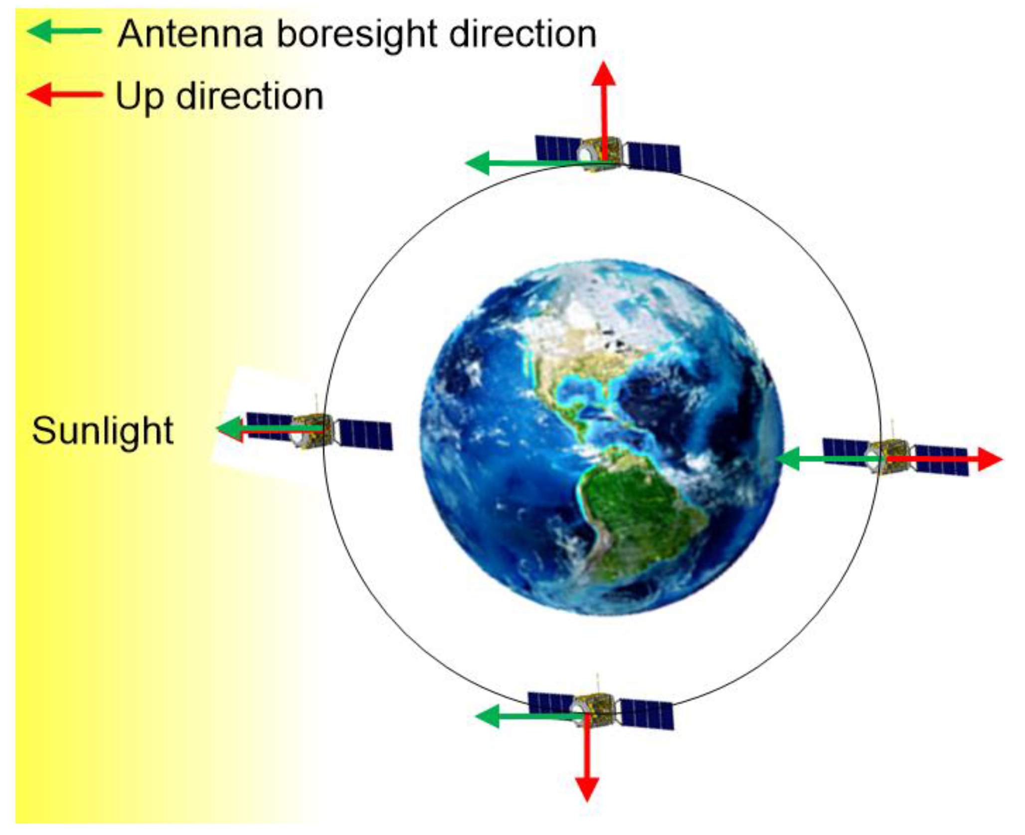
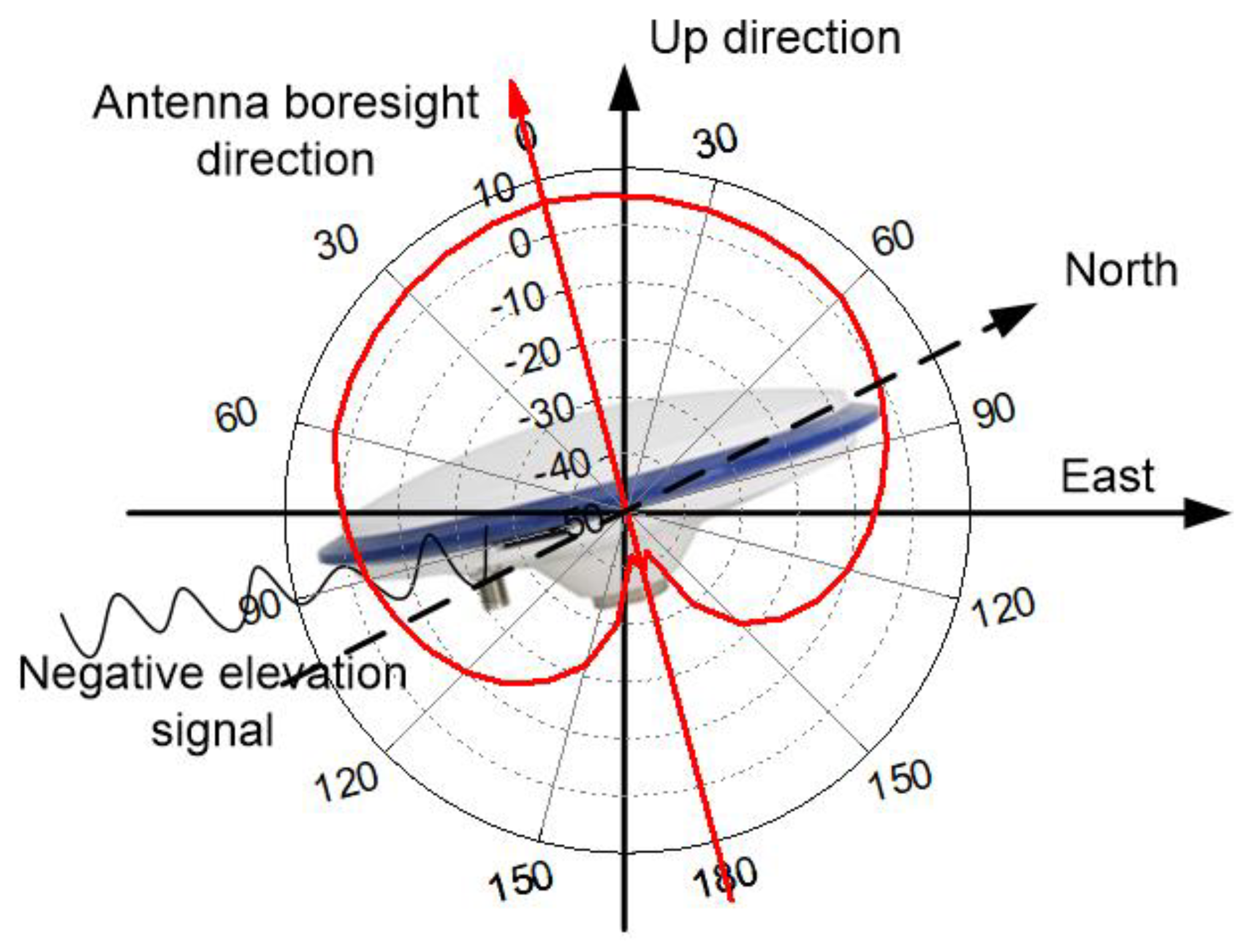
2.2. Weighting Model with C/N0 for the Sun-Pointing Attitude Mode

One of the most significant characteristics for the onboard GNSS receiver of the LEO satellite with the sun-pointing attitude mode is that the antenna boresight direction of the GNSS receiver depends on the satellite attitude mode. The GNSS antenna is installed on the same side as the solar panel and fixed to the LEO satellite. The antenna boresight direction can be defined in the satellite body-fixed frame and always points to the sun. Figure 1 shows the impact of the sun-pointing satellite attitude.
The local Cartesian coordinate system with the origin at the GNSS phase center of the LEO satellite is used to calculate the nominal elevation. The up direction points towards outer space, as shown in Figure 1. The GNSS antenna boresight for ground-based applications normally coincides with the up direction, while the onboard GNSS antenna boresight depends on the satellite attitude. For the earth-pointing attitude mode, the boresight direction may be the same as the up direction. For the sun-pointing attitude mode, the boresight direction depends on the geometrical relationship between the satellite, the earth, and the sun. The motion of the LEO satellite around the earth produces a changing discrepancy between the antenna boresight direction and the up direction. The boresight direction presents a large discrepancy with the up direction, which has a strong impact on the GNSS signal. The impact depends on the antenna radiation pattern, which is illustrated in Figure 2.
Since the antenna radiation pattern is almost the same at different azimuth angles, we only present the antenna radiation pattern at azimuth zero for clarity. The red curve denotes the gain variation of signal strength as the variation of the elevation angle at azimuth zero. The radiation pattern indicates that the antenna gain decreases from the antenna boresight direction to the low-elevation angle. Consequently, the low-elevation GNSS signal has lower signal strength and larger noise than the high-elevation signal. However, this is not the case for the onboard GNSS antenna due to its sun-pointing attitude mode. The impact of the satellite attitude on the onboard GNSS signal tracking are as follows: (1) some low-elevation angle signals become trackable, and correspondingly, a portion of high-elevation angle signals becomes ‘invisible’; (2) the relationship between the observation noise and the elevation angle is changed due to the radiation pattern rotation. The radiation pattern is fixed to the antenna and rotates along with the satellite platform, which changes the theoretical carrier-to-noise ratio (C/N0) of the tracked signals and changes the noise characteristics correspondingly.
In this study, the satellite attitude impact on the GNSS observations is described using a suitable weighting model. Observation weighting is an essential component of the weighting model and plays a key role in reliable parameter estimation [37]. For the ground receiver, the elevation-dependent function may be reasonable to capture the observation noise characteristics, while it may not always remain valid for the onboard GNSS receivers. For example, some low-cost LEO satellites may have no rotation angle information of the antenna plane so that true elevation cannot be computed. The nominal elevation is computed relative to the local horizontal plane and the negative elevation may occur. Many observations below the elevation mask will be excluded even though they have good noise characteristics. When the boresight direction of the GNSS antenna does not coincide with the zenith direction, the weighting model based on the elevation angle becomes unrealistic for data processing. Instead, the C/N0 can always reflect the strength of the signal and can be used as a measurement noise indicator. Research results demonstrate that the estimate of single-antenna attitude systems based on the signal strength measurements is feasible in theory [38]. Therefore, we established a C/N0-based weighting model to accommodate the LEO satellite attitude impact, which can be expressed as follows:
M P ( C / N 0 ) = a + b 1 e 1 / ( C / N 0 25 ) 2
where MP(C/N0) represents the multipath and measurement noise; C/N0 is the carrier-to-noise ratio; a and b are coefficients. A secondary benefit of the model is that it automatically extends the weighting model to the low or negative elevation cases. The elevation-dependent function can properly handle the high elevation angle observations but is not always reasonable for the low and negative elevation cases.
The C/N0-based weighting model can be built in advance using previous observations and then applied in the real LEO KOD. To build the weighting model, the coefficient a and b are obtained with the minimum norm quadratic unbiased estimation (MINQUE) [39]. In the MINQUE method, the carrier-to-noise ratio C / N 0 is directly provided by the onboard GNSS receiver. The multipath and measurement noise can be computed with constructing the code-phase linear combination and handling ionosphere and ambiguity [40]. Since the majority of bias terms in the code and phase measurements are the same, thus the code noise can be isolated with the code–phase combination
P r s L r s 2 I r s + λ s B r s + ε p s ε l s
where the symbols are defined as above. The carrier phase noise is only about 1/100 of the code noise, so the phase noise is ignorable. The ionosphere and ambiguity biases can be handled by the time-difference method. If cycle slips occur, the corresponding code-phase combinations are not considered.
In the MINQUE model, the variance–covariance (vc-) matrix of the observations can be expressed as:
Q y y = i = 1 m σ i 2 Q i
where σ i 2 is the variance component. The MINQUE method attempts to construct a quadratic form y T M y to estimate the vc-matrix. y is the observation residual and M is a matrix to be constructed meeting three conditions: invariant, unbiasness and minimum norm. The three conditions can be equivalently expressed as:
t r ( M A ) = 0 σ ^ i 2 = t r ( M Q i ) t r ( M Q M Q ) = min
where t r ( ) is the trace operator of a matrix Q = i = 1 m Q i . The problem can be equivalently converted to a constrained minimum optimization problem and solved with the Lagrange multiplier algorithm. With the matrix M determined, the variance components can be estimated with a least-squares procedure.
The full variance of the OMC observations can be expressed as the sum of the variances of measurement noise, satellite orbit correction, satellite clock offset correction, and prior ionospheric correction. The measurement noise of the pseudorange observation or carrier phase observation is proportional to the square of the pseudorange chip length or carrier phase wavelength [41]. Considering the presumption of much higher precision of phase observations than code observations, the phase multipath and noise can be ignored in the GRAPHIC observation [42]. According to error propagation law, the complete weighting model is as follows:
{ σ p ¯ 2 = σ o r b 2 + σ c l k 2 + σ i o n 2 + φ 2 ( C / N 0 ) σ g ¯ 2 = σ o r b 2 + σ c l k 2 + φ 2 ( C / N 0 ) / 4
where σ orb 2 and σ clk 2 are the variance of precise satellite orbit and clock offset correction, respectively.

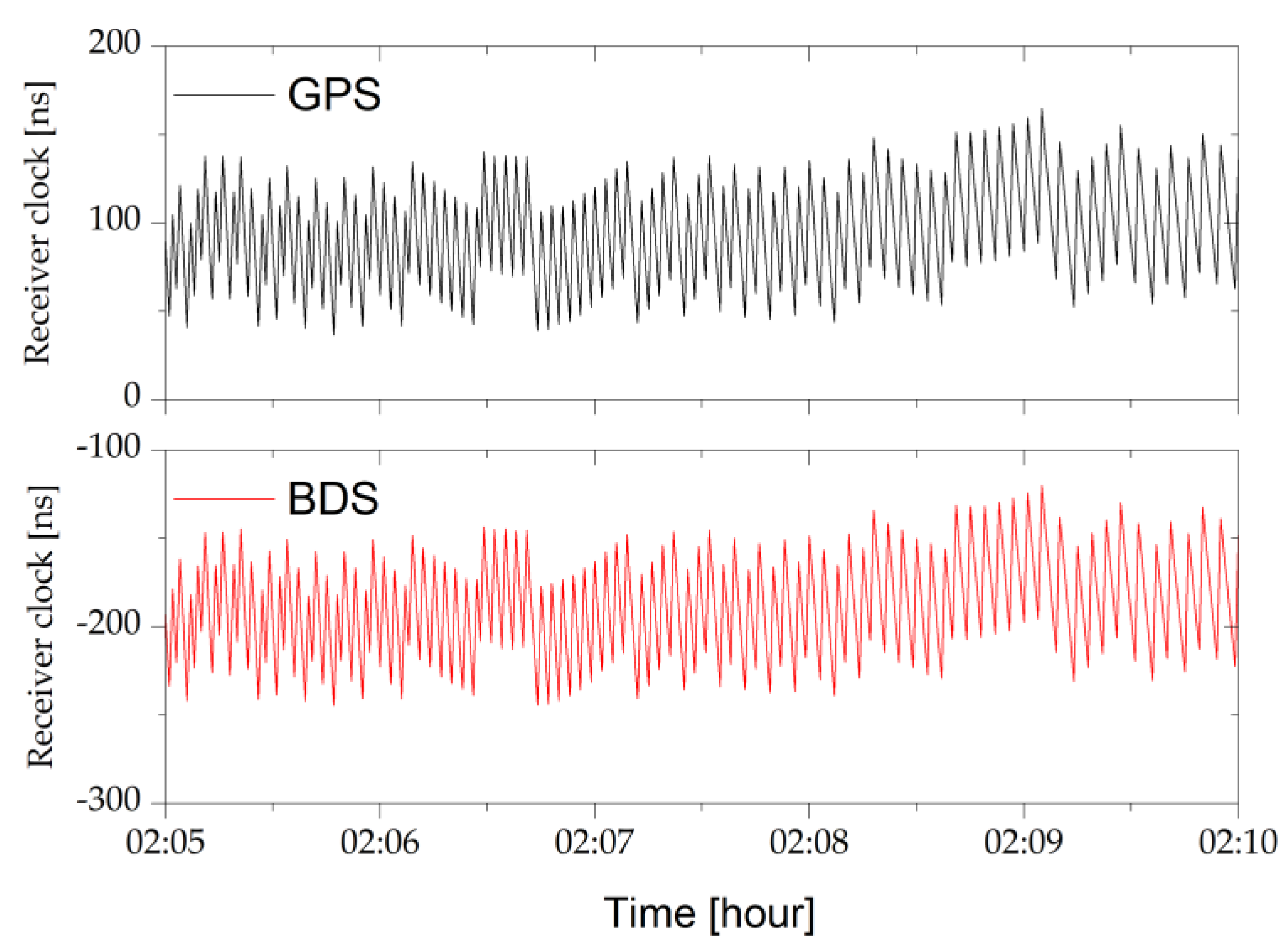
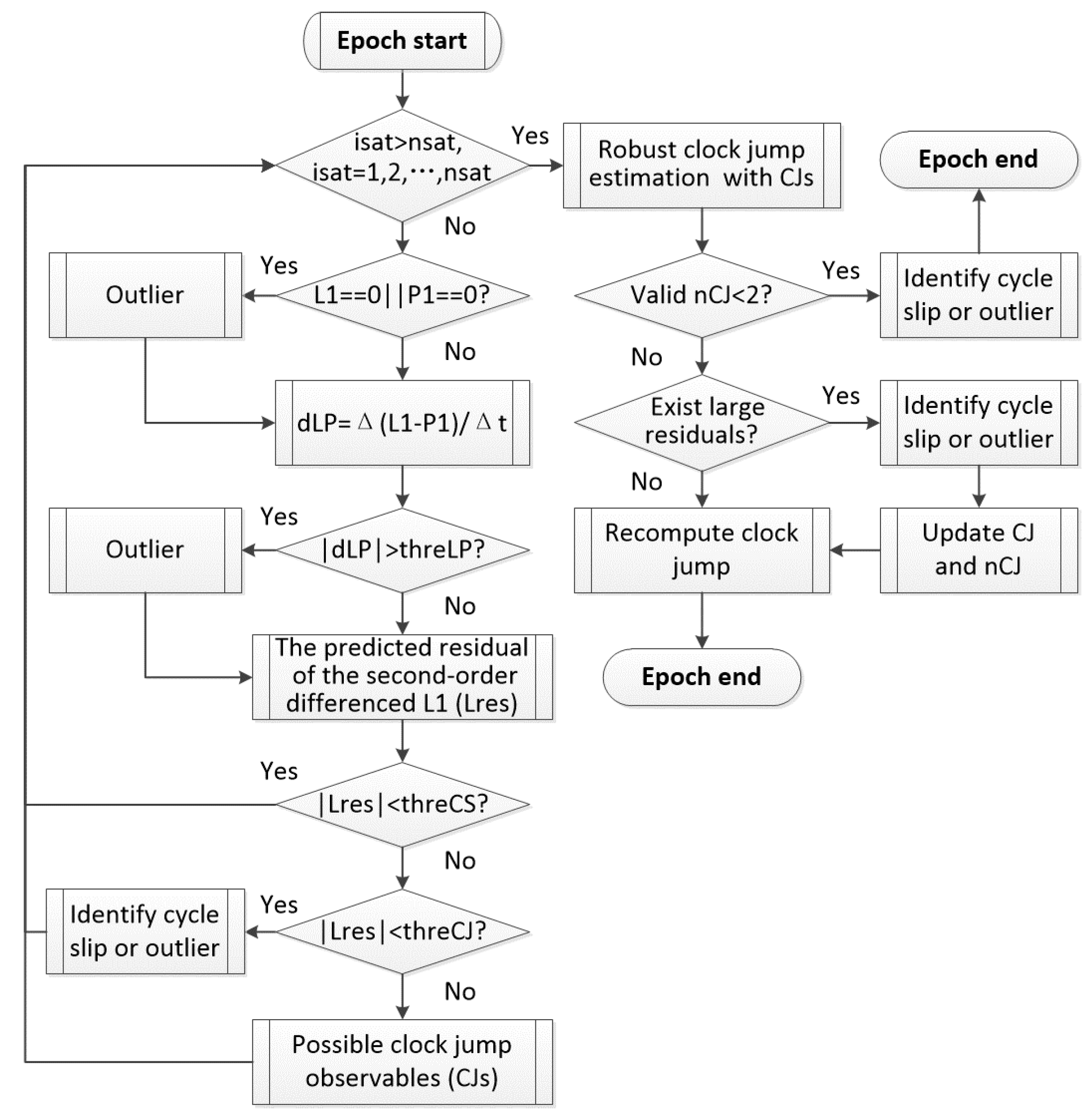
2.3. Joint Detection of Clock Jump and Cycle Slip for the Single-Frequency Data

The clock steering is a routine operation to constrain the receiver clock bias since the large bias affects the signal tracking and orbit computation. During the clock steering event, the pseudorange and carrier phase measurements from all satellites are shifted by the same amount, which is equivalent to a receiver clock jump. It has no impact on computing orbit if the receiver clock is modeled as the white noise process. However, frequent clock steering events will be a challenge in cycle slip detection. The clock steering events can be reflected in the GPS and BDS receiver clock series, which are shown in Figure 3. To improve the readability of the figure, only five-minute receiver clock series are represented. It can be seen that about 90 clock steering events happen in five minutes. Consequently, a constant bias is introduced in the phase observation and will be incorrectly identified as one cycle slip if the detection algorithm does not consider the clock steering events.
A high-order time difference (HTD) approach based on the carrier phase is capable of handling the high-dynamic single-frequency cycle slip detection, while it cannot cope with the receiver clock steering. Unfortunately, the Luojia-1A onboard receiver employs frequent clock steering for maintaining reasonable time synchronization. The clock steering means that the pseudorange and carrier phase measurements of all satellites are adjusted to control the receiver clock bias, which may affect cycle slip detection. Therefore, the receiver clock jump must be considered in a single-frequency cycle slip detection algorithm. To solve this problem, the optimized algorithm flowchart is shown in Figure 4.
The real-time single-frequency receiver clock jump and cycle slip detection algorithm with only several adjacent data contains three steps: (1) the data preprocessing, (2) the cycle slip and clock jump detection, and (3) the clock jump estimation. In the data preprocessing, some abnormal observations are first screened by judging whether the carrier phase observation L1 or the pseudorange observation P1 is zero. The epoch-differenced L1–P1 (dLP) observable is used to detect outliers since it is insensitive to clock jumps if the single-frequency pseudorange and phase observations are consistent. The noise of the dLP observable is typically 3–5 m [43], and its threshold value (threLP) can be set as four times this noise. The second-order differenced carrier phase time series is generated in the second step, and the linear prediction model with the previous several epochs is used for the cycle slip and clock jump detection. The predicted residual with respect to the real second-order differenced phase (Lres) reflects the impact of the receiver–satellite kinematic and the remaining ionospheric delay, which is much smaller than the phase jump such as the clock cycle, outlier, or clock jump. Cycle slips or outliers will be identified if the predicted residual falls between the threshold values of cycle slip (threCS) and clock jump (threCJ), which are set as 3.0 cycles and 10.0 cycles based on the noise of observable and the steering mechanism, respectively. Since the phase outlier causes two adjacent abnormal detection results and the cycle slip only influences the current result, they can be further discriminated. In the third step, the clock jump can be estimated robustly with the possible clock jump (CJ) observables whose total number is defined as the nCJ. The cycle slips and outliers are also detected according to the residuals of CJ observables.

3. Results and Analysis

To validate the proposed weighting model and the single-frequency cycle slip detection algorithm considering LEO onboard receiver clock jumps, the Luojia-1A onboard GNSS data description and the basic processing configuration are discussed first. The GPS/BDS single-frequency KOD considering the above model and algorithm strategy is then analyzed and validated.

3.1. Data Description and Processing Configuration

The Luojia-1A satellite was designed by Wuhan University, China and launched successfully on 2 June 2018. Its mission objective is to test nighttime light remote sensing and LEO-based navigation augmentation [44]. The satellite is operating on a 645 km orbit and weighs about 19.8 kg. The outlook of the Luojia-1A satellite is demonstrated in Figure 5. The Luojia-1A satellite onboard the GNSS receiver is developed by the China electronics technology group corporation (CETC). The onboard receiver is capable of tracking GPS L1/L2 and BDS B1I/B2I signals and simultaneously up to 12 satellites for each signal. It should be mentioned that this receiver only tracks the BDS regional system at present and the next mission will support the global system in the future.
Due to the platform energy constraint of the Luojia-1A satellite, the dual-frequency GNSS receiver is only active during the mission period. Only GPS/BDS data on 8 June 2018 with a 1 s sampling interval were collected in this experiment. In this study, we used GPS L1 and BDS B1 measurements for validating the proposed weighting model and single-frequency cycle slip detection algorithm. The dual-frequency reduced-dynamic orbit determination results, of which three-dimension overlapping precision is about 6.7 cm, are used as the reference orbit for evaluating the KOD accuracy using the proposed strategy [45]. Figure 6 shows the number of all visible satellites.
Figure 6 shows that the number of visible GPS satellites ranges from 6 to 12 for most epochs. The tracked signals of the BDS region system mainly cover the Asia-Pacific region. Since there are five GEO satellites and six IGSO satellites of BDS located over this region, the Luojia-1A satellite can track more BDS satellites in this region. However, the number of visible BDS satellites tracked by the Luojia-1A satellite decreases when the GEO and IGSO satellites are invisible. Therefore, the number of visible BDS satellites fluctuates periodically. The orbit solution will not be continuous if only BDS observations are used. Combining BDS and GPS is helpful to improve the number of available observations, which may benefit orbit determination. Hence, this article studies the benefit of using BDS measurements in GPS/BDS-combined single-frequency KOD.
The Luojia-1A satellite orbit is computed with the onboard GPS/BDS single-frequency observations in the offline processing mode. The extended Kalman filter is used for the orbit estimation where ambiguity states are passed from epoch to epoch, while LEO satellite position and receiver clock are freely adjusted at each epoch. One new ambiguity parameter is set and estimated as a float constant when a cycle slip occurs or a new arc begins. Precise GPS/BDS orbit and clock products are used for decreasing model error while the real LEO KOD for onboard applications generally works with broadcast ephemerides. The detailed data processing configuration is listed in Table 1. The GPS differential P1C1 code bias products from the center for orbit determination in Europe (CODE) analysis center are used to correct the C1 code, and the P1P2 products are used to correct the bias term introduced by precise satellite clock products. The correction of timing group delays for the BDS satellite is ignored in the processing of the B1 observations since BDS B1B2 products are not publicly available at present. Although it may decrease the accuracy of kinematic positioning, the validation of the proposed weighting model and single-frequency cycle slip detection is not influenced.

3.2. Validation of the C/N0 Based Weighting Model

Luojia-1A is a nanosatellite that employs the sun-pointing attitude mode differently from that of GPS satellites. In Luojia-1A, the negative Z-axis is fixed toward the sun to obtain enough energy in standby mode, so the boresight direction of the GNSS antenna does not always point toward the zenith direction. Consequently, the C/N0 of the GNSS signals collected from the onboard receivers is significantly different from that of the ground receiver. The elevation dependence on the C/N0 of GPS/BDS measurements collected from the Luojia-1A satellite is presented in Figure 7.
Figure 7 indicates that the satellite is capable of tracking observations of low-elevation angles, even negative angles, and the low-elevation measurements (<20°) contribute to about 50% of total measurements. The LEO onboard receiver still tracks the signals with a sufficient amount of C/N0 strength, which shows a parabolic relationship with the elevation angle caused by the satellite attitude mode. The C/N0 in Figure 7 denotes the average value in the range of ten degrees. The average C/N0 is calculated every ten degrees as the elevation angle increases. It can be seen from Figure 7 that the signal strength of observations from the LEO onboard receiver in the range of −10° to 10° elevation is close to that of the 10° to 20° elevation angle and is on average 1.8 dB-Hz lower than that above the 20° elevation angle. It shows that the signal strength of the −10° to 10° elevation angle observations has about the same data quality as that of the observations in the range of 10° to 20° elevation. Therefore, the low-elevation observations can be used if a suitable weighting model is built for the LEO KOD.
The elevation-dependent weighting model cannot describe the data quality of low-elevation observations correctly for the sun-pointing attitude mode. To build and validate the C/N0-based weighting model, the multipath and observation noise of the pseudorange is first calculated and is both geometry-free and ionosphere-free. The ambiguity biases are assumed to be constant unless there is a slip in the tracking of phases. The effect of the phase multipath is much smaller in magnitude than the pseudorange multipath, and thus can be neglectable. To cope with the satellite attitude impact, the weighting model is established in advance based on the variation of the multipath and observation noise with the C/N0 for the onboard Luojia-1A GNSS receiver, which is presented in Figure 8.
Figure 8 indicates that the multipath and observation noise is strongly correlated to the C/N0, and thus the weighting model is reasonable, especially during the attitude maneuver. The observations with C/N0 below 30 dB-Hz are not considered in this study. According to the MINQUE method, the estimated coefficients and of the proposed C/N0-based weighting model are 663.826 and −664.125, respectively. The dashed line in the figure shows the 95% confidence level of the observation noise, which agrees well with the data. It should be mentioned that the coefficients are the same for GPS and BDS because they are estimated with both GPS and BDS L1 measurements. Considering that the C/N0 characteristics may vary in different constellations and signals, but we are limited by the length of this paper, so in the next step it is worth conducting further comprehensive research on different models for GPS and BDS, respectively, even for each satellite signal.

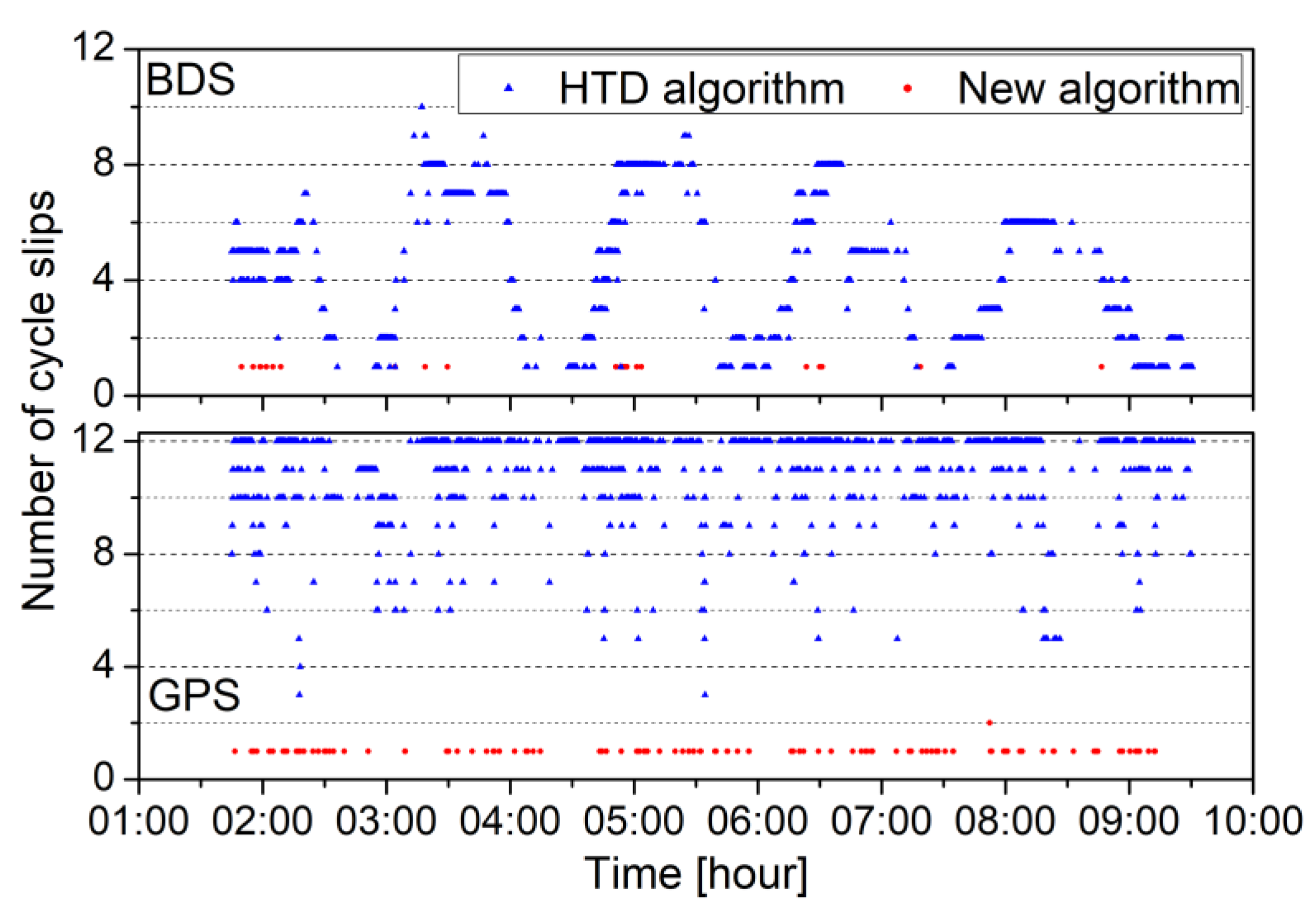
3.3. Validation of Single-Frequency Cycle Slip Detection

Correct cycle slip detection is one important factor in achieving a reliable estimation. The GNSS receiver on board the Luojia-1A satellite relies on a standard temperature-compensated oscillator without discipline, and the clock steering events occur frequently. The GNSS receiver clock steering of the LEO satellite at high speeds makes single-frequency cycle slip detection ineffective and difficult. Figure 9 shows the number of cycle slips detected by the HTD algorithm and the proposed algorithm on each epoch.
In general, the number of cycle slips is very small compared to that of observations. However, many cycle slips are incorrectly identified by the HTD algorithm since the cycle slip detection based on the carrier phase is impacted by the frequent receiver clock steering events, although the HTD algorithm can resist high dynamics of the satellite platform. The new algorithm is independent of the clock steering events and provides more reasonable cycle slip detection. The number of actual cycle slips is 59 and 21, accounting for 0.020% and 0.018% of all GPS and BDS observations, respectively. Considering the carrier phase outliers, the number of cycle slips and outliers increases to 168 and 27 for GPS and BDS, and the percentage is 0.056% and 0.024%, respectively. If cycle slips are detected, new ambiguity parameters will be introduced into the KOD estimator. This can protect against the erroneous estimation of the ambiguity parameter and contamination of KOD results.

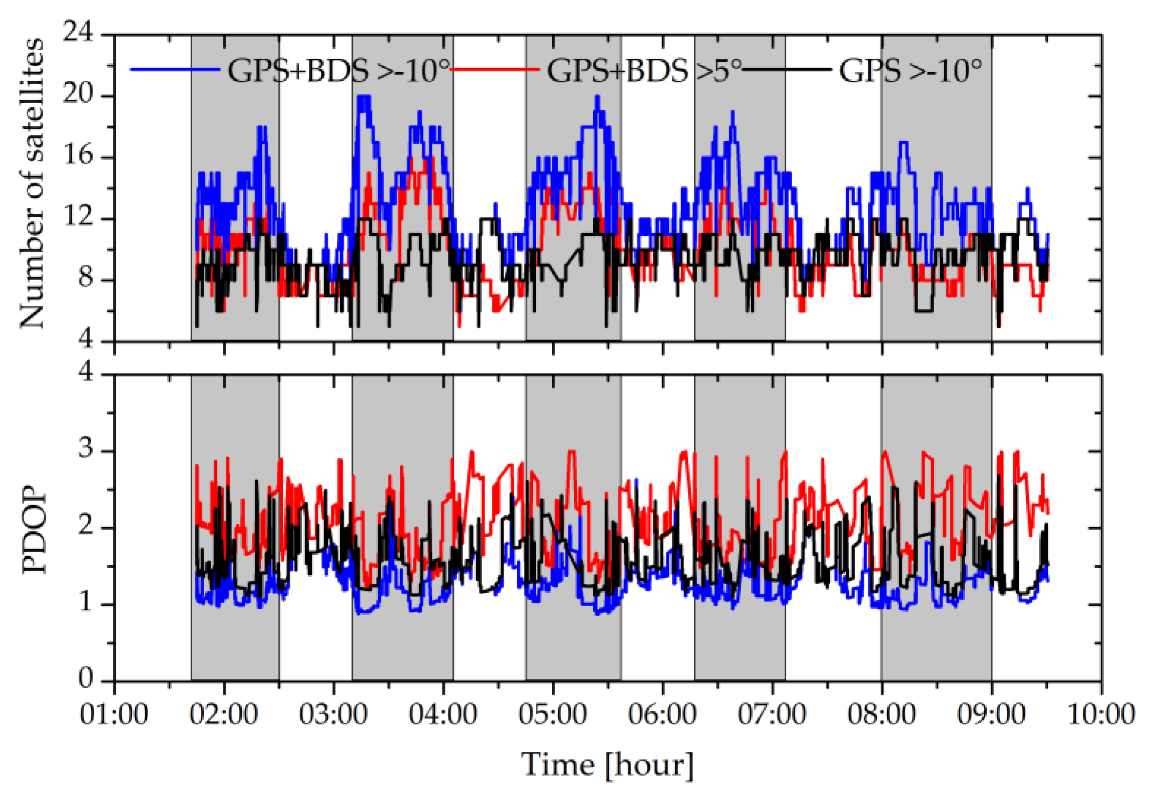
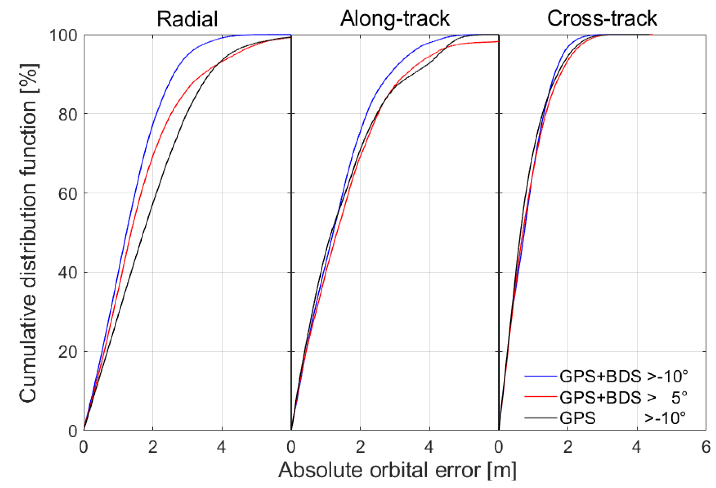
3.4. GPS/BDS Single-Frequency KOD Analysis of Luojia-1A Satellite

Orbit determination of the Luojia-1A using the C/N0-based weighting model considering the attitude impact is evaluated by adding low-elevation observations with the single-frequency KOD strategy. To validate the feasibility of the proposed weighting model, GPS/BDS observations from the Luojia-1A satellite between −10°and 5° elevation angles are used in one scheme. For the GPS/BDS combination case, the number of satellites above the 5° and −10° elevation mask and the position dilution of precision (PDOP) values are compared in Figure 10. It might be also interesting to investigate the contribution of the GPS and BDS combination in the single-frequency LEO KOD. To validate the speculation that combining BDS and GPS may benefit orbit determination and demonstrate the impact of the fluctuating number of visible BDS satellites, the contribution of BDS is analyzed using the observations from satellites above the −10° elevation mask.
Figure 10 shows that the number of available satellites ranges from 5 to 20 and the PDOP value ranges from 0.875 to 2.685 for the −10° elevation mask scheme in the GPS/BDS combination, denoted by the blue line. There is an average of 10 satellites available above the 5° elevation angle and an average of 13 satellites above the −10° elevation angle, achieving 37.5% improvement in PDOP by decreasing the elevation cutoff angle to −10°. The shadow area shows that BDS has a clear contribution to both the number of available satellites and the PDOP when the Luojia-1A satellite flies over China, since the orbit period of the Luojia-1A satellite is approximately 96 min, and Luojia-1A is designed to track the signals of the BDS regional system. During these periods, the GPS/BDS combination has on average five satellites more than the GPS-only case. The average PDOP for the cases of single GPS and the GPS/BDS combination are 1.526 and 1.277, respectively, which is an improvement of 16.3%.
The impact of low-elevation angle measurements on orbit determination and the contribution of BDS to the KOD is shown in Figure 11, which is the cumulative distribution function of absolute orbital error in the radial, along-track, and cross-track directions, respectively. The kinematic orbital error is also evaluated in terms of root mean square (RMS) error. Table 2 shows the statistical performance of the positioning accuracy.
Figure 11 shows that the orbital error obtained from the −10° elevation mask scheme in the GPS/BDS combination denoted with the blue line is the best in all components. The reason is that the number of available satellites increases remarkably and large residuals can be removed from the observations. Compared to the −10° elevation mask scheme, 12.9% of epochs cannot be utilized for the 5° elevation mask scheme with the red line whose RMS values of the orbital error are 2.104, 2.069, and 1.057 m in the radial, along-track, and cross-track directions. As shown in Table 2, when using observations from satellites between −10° and 5° elevations, the orbital RMS precision values reach 1.640, 1.729, and 0.988 m, which are improved by 22.1%, 16.4%, and 6.5% in the radial, along-track, and cross-track directions, respectively.
As expected, GPS/BDS-combined KOD results are better than that of the GPS-only case with the black line since BDS makes a contribution to both the number of available satellites and the PDOP in the Asia-Pacific region. Some low-quality measurements can be also eliminated easily and do not remarkably decrease the number of redundant observations. For the GPS-only solution, the RMS values of the orbital error are 2.302, 1.965, and 0.993 m in the radial, along-track, and cross-track directions, respectively. The GPS/BDS combination improves the estimation precision of the ambiguity parameter, and the residuals are reliable since outliers are removed correctly. As a result, the orbital RMS precision values of the GPS/BDS-combined solution are improved by 28.8%, 12.0%, and 0.5% in the radial, along-track, and cross-track directions, respectively.

4. Discussions and Conclusions

The KOD method using the LEO satellite onboard single-frequency GNSS observations is a cost-effective solution for future commercial aerospace applications. In this study, the improved data processing strategy of GPS/BDS-combined single-frequency KOD is proposed for the LEO satellite using the sun-pointing attitude mode. The satellite attitude impact on the GNSS observations is analyzed, and results show the theoretical C/N0 of the tracked signals and the noise characteristics change as the antenna radiation pattern rotates. To process this situation, an observation weighting model based on the C/N0 characteristic and exponential function is developed. The coefficients of this weighting model can be estimated and then applied in the real LEO KOD. Experiments show that this weighting model is suitable for processing the GPS/BDS observations from the LEO satellite with the sun-pointing attitude mode.
The real-time single-frequency cycle slip detection algorithm with the capacity of handling receive clock jump is developed for improving the single-frequency carrier phase preprocessing. This method is designed to compute the phase acceleration jump based on a linear model and employs a robust approach in the estimation of the receiver clock jump. The cycle slip and clock jump can be identified, respectively. Moreover, cycle slips/outliers can be further discriminated using two adjacent detection results. This algorithm is independent of the clock steering events and can reasonably detect cycle slips in the GPS/BDS data preprocessing of the LEO satellite.
The GPS/BDS-combined single-frequency KOD results of the Luojia-1A satellite show that the above improved data-processing strategy is suitable for LEO satellites with the sun-pointing attitude mode. Considering the unique feature of the Luojia-1A sun-pointing satellite attitude mode, incorporating low-elevation observations can improve data availability and orbit accuracy. The number of valid epochs and the PDOP values are improved by 12.9% and 37.5%, respectively, when using observations from satellites between −10° and 5° elevation. As a result, the orbital RMS accuracy of the GPS/BDS-combined single-frequency KOD can be improved by 22.1%, 16.4%, and 6.5% in the radial, along-track, and cross-track directions, respectively. The contribution of the BDS observations is also analyzed for the Luojia-1A KOD based on the processing strategy. Compared with the GPS-only case, the orbital RMS accuracy of the GPS/BDS combination solution is improved up to 28.8%. The benefit of combining GPS/BDS observations in LEO KOD is demonstrated with the onboard GNSS data from the Luojia-1A satellite.

Author Contributions

W.F. designed the experiment and wrote the manuscript. L.W. edited this manuscript. R.C., H.Z., T.L. and Y.H. helped to improve the manuscript. All authors have read and agreed to the published version of the manuscript.

Funding

This work was supported by the Program of the National Natural Science Foundation of China (Nos. 41904038, 42074036, 41704002, and 91638203) and the China Postdoctoral Science Foundation (No. 2019M662713), and LIESMARS Special Research Funding.

Data Availability Statement

The GNSS precise satellite orbit and clock products provided by the Crustal Dynamics Data Information System (CDDIS) (Greenbelt, MD, USA) are available at ftp://cddis.gsfc.nasa.gov/gps/products/mgex. Luojia-1A onboard GNSS data on the re-sults of this study are currently not in the public domain and therefore cannot be accessed online. Data requests can be sent to the corresponding authors in case of specific interests.

Acknowledgments

The authors thank the reviewers for their beneficial comments and suggestions.

Conflicts of Interest

The authors declare no conflict of interest.

References

  1. Bertiger, W.I.; Bar-Sever, Y.E.; Christensen, E.J.; Davis, E.S.; Guinn, J.R.; Haines, B.J.; Ibanez-Meier, R.W.; Jee, J.R.; Lichten, S.M.; Melbourne, W.G.; et al. GPS precise tracking of TOPEX/POSEIDON: Results and implications. J. Geophys. Res. 1994, 99, 24449. [Google Scholar] [CrossRef]
  2. Melbourne, W.G.; Davis, E.S.; Yunck, T.P.; Tapley, B.D. The GPS flight experiment on TOPEX/POSEIDON. Geophys. Res. Lett. 1994, 21, 2171–2174. [Google Scholar] [CrossRef] [Green Version]
  3. Schutz, B.E.; Tapley, B.D.; Abusali, P.A.M.; Rim, H.J. Dynamic orbit determination using GPS measurements from TOPEX/POSEIDON. Geophys. Res. Lett. 1994, 21, 2179–2182. [Google Scholar] [CrossRef]
  4. Bruinsma, S.; Loyer, S.; Lemoine, J.M.; Perosanz, F.; Tamagnan, D. The impact of accelerometry on CHAMP orbit determination. J. Geod. 2003, 77, 86–93. [Google Scholar] [CrossRef]
  5. Haines, B.; Bar-Sever, Y.; Bertiger, W.; Desai, S.; Willis, P. One-centimeter orbit determination for Jason-1: New GPS-based strategies. Mar. Geod. 2004, 27, 299–318. [Google Scholar] [CrossRef]
  6. Kang, Z.; Tapley, B.; Bettadpur, S.; Ries, J.; Nagel, P.; Pastor, R. Precise orbit determination for the GRACE mission using only GPS data. J. Geod. 2006, 80, 322–331. [Google Scholar] [CrossRef]
  7. Van den Ijssel, J.; Encarnação, J.; Doornbos, E.; Visser, P. Precise science orbits for the Swarm satellite constellation. Adv. Space Res. 2015, 56, 1042–1055. [Google Scholar] [CrossRef]
  8. Peter, H.; Jäggi, A.; Fernández, J.; Escobar, D.; Ayuga, F.; Arnold, D.; Wermuth, M.; Hackel, S.; Otten, M.; Simons, W.; et al. Sentinel-1A—First precise orbit determination results. Adv. Space Res. 2017, 60, 879–892. [Google Scholar] [CrossRef]
  9. Sun, Y.; Bai, W.; Liu, C.; Liu, Y.; Du, Q.; Wang, X.; Yang, G.; Liao, M.; Yang, Z.; Zhang, X.; et al. The FengYun-3C radio occultation sounder GNOS: A review of the mission and its early results and science applications. Atmos. Meas. Tech. 2018, 11, 5797–5811. [Google Scholar] [CrossRef] [Green Version]
  10. Jäggi, A.; Hugentobler, U.; Beutler, G. Pseudo-Stochastic Orbit Modeling Techniques for Low-Earth Orbiters. J. Geod. 2006, 80, 47–60. [Google Scholar] [CrossRef] [Green Version]
  11. Bock, H.; Jäggi, A.; Švehla, D.; Beutler, G.; Hugentobler, U.; Visser, P. Precise orbit determination for the GOCE satellite using GPS. Adv. Space Res. 2007, 39, 1638–1647. [Google Scholar] [CrossRef]
  12. Li, J.; Zhang, S.; Zou, X.; Jiang, W. Precise orbit determination for GRACE with zero-difference kinematic method. Chin. Sci. Bull. 2009, 55, 600–606. [Google Scholar] [CrossRef]
  13. Montenbruck, O.; Gill, E.; Kroes, R. Rapid orbit determination of LEO satellites using IGS clock and ephemeris products. GPS Solut. 2005, 9, 226–235. [Google Scholar] [CrossRef]
  14. Peng, D.; Wu, B. Zero-difference and single-difference precise orbit determination for LEO using GPS. Chin. Sci. Bull. 2007, 52, 2024–2030. [Google Scholar] [CrossRef]
  15. Svehla, D.; Rothacher, M. Kinematic orbit determination of LEOs based on zero or double-difference algorithms using simulated and real SST GPS data. In Vistas for Geodesy in the New Millennium; Adam, J., Schwarz, K.P., Eds.; Springer: Berlin/Heidelberg, Germany, 2002; Volume 125, pp. 322–328. [Google Scholar]
  16. Zhu, S.; Reigber, C.; König, R. Integrated adjustment of CHAMP, GRACE, and GPS data. J. Geod. 2004, 78, 103–108. [Google Scholar] [CrossRef]
  17. Li, M.; Li, W.; Shi, C.; Jiang, K.; Guo, X.; Dai, X.; Meng, X.; Yang, Z.; Yang, G.; Liao, M. Precise orbit determination of the Fengyun-3C satellite using onboard GPS and BDS observations. J. Geod. 2017, 91, 1313–1327. [Google Scholar] [CrossRef] [Green Version]
  18. Li, X.; Ma, F.; Li, X.; Lv, H.; Bian, L.; Jiang, Z.; Zhang, X. LEO constellation-augmented multi-GNSS for rapid PPP convergence. J. Geod. 2018, 93, 749–764. [Google Scholar] [CrossRef]
  19. Weinbach, U.; Schön, S. Improved GRACE kinematic orbit determination using GPS receiver clock modeling. GPS Solut. 2012, 17, 511–520. [Google Scholar] [CrossRef]
  20. Sun, X.; Han, C.; Chen, P. Real-time precise orbit determination of LEO satellites using a single-frequency GPS receiver: Preliminary results of Chinese SJ-9A satellite. Adv. Space Res. 2017, 60, 1478–1487. [Google Scholar] [CrossRef]
  21. Montenbruck, O.; Gill, E.; Markgraf, M. PHOENIX-XNS-A miniature real-time navigation system for LEO satellites. In Proceedings of the 3rd ESA Workshop on Satellite Navigation User Equipment Technologies, Noordwijk, The Netherlands, 11–13 December 2006. [Google Scholar]
  22. Montenbruck, O.; Ramos-Bosch, P. Precision real-time navigation of LEO satellites using global positioning system measurements. GPS Solut. 2008, 12, 187–198. [Google Scholar] [CrossRef]
  23. Chen, P.; Zhang, J.; Sun, X. Real-time kinematic positioning of LEO satellites using a single-frequency GPS receiver. GPS Solut. 2016, 21, 973–984. [Google Scholar] [CrossRef] [Green Version]
  24. Bock, H.; Jäggi, A.; Dach, R.; Schaer, S.; Beutler, G. GPS single-frequency orbit determination for low Earth orbiting satellites. Adv. Space Res. 2009, 43, 783–791. [Google Scholar] [CrossRef]
  25. Hwang, Y.; Born, G.H. Orbit determination strategy using single-frequency global-positioning-system data. J. Spacecr. Rocket. 2005, 42, 896–901. [Google Scholar] [CrossRef]
  26. Kahr, E.; Montenbruck, O.; O'Keefe, K.; Skone, S.; Urbanek, J.; Bradbury, L.; Fenton, P.C. GPS Tracking on a nanosatellite- the CANX-2 Flight experience. In Proceedings of the 8th International ESA Conference on Guidance, Navigation & Control Systems, Carlsbad, Czech Republic, 5-10 June 2011. [Google Scholar]
  27. Gill, E.; Montenbruck, O.; Brieb, K. GPS-Based Autonomous Navigation for the BIRD Satellite. In Proceedings of the International Symposium Space Flight Dynamics, Biarritz, France, 26–30 June 2000. [Google Scholar]
  28. Montenbruck, O.; Markgraf, M.; Santandrea, S.; Garcia, A.; Issler, J.-L.; Mercier, F.; Naudet, J.; Serre, S. GPS based Precise Orbit Determination and Real time Navigation of the PROBA2 spacecraft. In Proceedings of the 5th ESA Workshop on Satellite Navigation Technologies, Noordwijk, The Netherlands, 8–10 December 2010. [Google Scholar]
  29. Yunck, T.P. Orbit determination. In Global Positioning System—Theory and Applications; Parkinson, B.W., Spilker, J.J., Eds.; AIAA: Washington, DC, USA, 1996. [Google Scholar]
  30. Nava, B.; Coïsson, P.; Radicella, S.M. A new version of the NeQuick ionosphere electron density model. J. Atmos. Sol.-Terr. Phys. 2008, 70, 1856–1862. [Google Scholar] [CrossRef]
  31. Peng, Y.; Scales, W.A.; Lin, D. GNSS-based hardware-in-the-loop simulations of spacecraft formation flying with the global ionospheric model TIEGCM. GPS Solut. 2021, 25, 1–14. [Google Scholar] [CrossRef]
  32. Jakowski, N.; Hoque, M.M.; Mayer, C. A new global TEC model for estimating transionospheric radio wave propagation errors. J. Geod. 2011, 85, 965–974. [Google Scholar] [CrossRef]
  33. Klobuchar, J.A. Ionospheric time-delay algorithm for single-frequency GPS users. IEEE Trans. Aerosp. Electron. Syst. 1987, 23, 325–331. [Google Scholar] [CrossRef]
  34. Montenbruck, O.; Gill, E. Ionospheric Correction for GPS Tracking of LEO Satellites. J. Navig. 2002, 55, 293–304. [Google Scholar] [CrossRef] [Green Version]
  35. Lou, Y.D.; Zheng, F.; Gu, S.F.; Wang, C.; Guo, H.L.; Feng, Y.M. Multi-GNSS precise point positioning with raw single-frequency and dual-frequency measurement models. Gps Solut. 2016, 20, 849–862. [Google Scholar] [CrossRef]
  36. Fu, W.; Huang, G.; Zhang, Q.; Gu, S.; Ge, M.; Schuh, H. Multi-GNSS real-time clock estimation using sequential least square adjustment with online quality control. J. Geod. 2019, 93, 963–976. [Google Scholar] [CrossRef]
  37. Luo, X.G.; Mayer, M.; Heck, B.; Awange, J.L. A realistic and easy-to-implement weighting model for GPS phase observations. Ieee Trans. Geosci. Remote Sens. 2014, 52, 6110–6118. [Google Scholar] [CrossRef]
  38. Wang, C.; Walker, R.A.; Moody, M.P. Single Antenna Attitude Algorithm for Nonuniform Antenna Gain Patterns. J. Spacecr. Rocket. 2007, 44, 221–229. [Google Scholar] [CrossRef] [Green Version]
  39. Rao, C.R. Estimation of variance and covariance components-MINQUE theory. J. Multivar. Anal. 1971, 1, 257–275. [Google Scholar] [CrossRef] [Green Version]
  40. Wang, L.; Feng, Y.; Wang, C. Real-time assessment of GNSS observation noise with single receivers. J. Glob. Position. Syst. 2013, 12, 73–82. [Google Scholar]
  41. de Bakker, P.F.; Tiberius, C.C.J.M. Real-time multi-GNSS single-frequency precise point positioning. GPS Solut. 2017, 21, 1791–1803. [Google Scholar] [CrossRef] [Green Version]
  42. Sterle, O.; Stopar, B.; Pavlovčič Prešeren, P. Single-frequency precise point positioning: An analytical approach. J. Geod. 2015, 89, 793–810. [Google Scholar] [CrossRef]
  43. Guo, F.; Zhang, X. Real-time clock jump compensation for precise point positioning. GPS Solut. 2013, 18, 41–50. [Google Scholar] [CrossRef]
  44. Wang, L.; Chen, R.; Li, D.; Zhang, G.; Shen, X.; Yu, B.; Wu, C.; Xie, S.; Zhang, P.; Li, M.; et al. Initial Assessment of the LEO Based Navigation Signal Augmentation System from Luojia-1A Satellite. Sensors 2018, 18, 3919. [Google Scholar] [CrossRef] [PubMed] [Green Version]
  45. Wang, L.; Xu, B.; Fu, W.; Chen, R.; Li, T.; Han, Y.; Zhou, H. Centimeter-Level Precise Orbit Determination for the Luojia-1A Satellite Using BeiDou Observations. Remote Sens. 2020, 12, 2063. [Google Scholar] [CrossRef]
  46. Wu, J.T.; Wu, S.C.; Hajj, G.A.; Bertiger, W.I.; Lichten, S.M. Effects of antenna orientation on GPS carrier phase. Manuscr. Geod. 1993, 18, 91–98. [Google Scholar]
Figure 1. Impact of the sun-pointing satellite attitude on the relationship between the GNSS antenna boresight direction (green arrow) and the up direction (red arrow).
Remotesensing 13 04020 g001
Figure 2. Sketch of the onboard GNSS antenna radiation pattern rotation. The red curve denotes the gain variation of signal strength. The rotation yields negative elevation signals and changes the noise characteristics.
Remotesensing 13 04020 g002
Figure 3. Frequent clock steering events captured in the GPS and BDS receiver clock series.
Remotesensing 13 04020 g003
Figure 4. Flowchart of the real-time single-frequency receiver clock jump and cycle slip detection algorithm. The joint detection algorithm can handle clock steering, and the cycle slip can be detected correctly in the case of receiver clock jump.
Remotesensing 13 04020 g004
Figure 5. Outlook configuration of the Luojia-1A satellite and the GNSS antenna.
Remotesensing 13 04020 g005
Figure 6. Number of visible GPS and BDS satellites.
Remotesensing 13 04020 g006
Figure 7. Percentage and signal strength of observations. The histogram is the percentage of observations and the blue line denotes the signal strength.
Remotesensing 13 04020 g007
Figure 8. Variation of the multipath and observation noise with the C/N0. The dashed line shows that the weighting model agrees well with the multipath and observation noise.
Remotesensing 13 04020 g008
Figure 9. Number of GPS and BDS cycle slips detected by the HTD algorithm and the new algorithm considering the clock steering events.
Remotesensing 13 04020 g009
Figure 10. Number of available satellites and PDOP values.
Remotesensing 13 04020 g010
Figure 11. Cumulative distribution function of absolute orbital error in the radial, along-track, and cross-track directions.
Remotesensing 13 04020 g011
Table 1. Processing configuration of the Luojia-1A kinematic orbit determination method with single-frequency data.
ItemsModels
ObservationsIonospheric-free L1 GRAPHIC combination and pseudorange observations
Observation weightProposed method
EstimatorExtended Kalman filter
Phase-windup effectCorrected [46]
Satellite antenna phase center and variationGPS, BDS: IGS14
Receiver antenna phase center and variationNot corrected
Tide displacementNot corrected
DCBsGPS P1C1/P1P2 product from CODE
Relativistic effectsCorrected (International Earth rotation and reference systems, IERS 2003)
Satellite orbit and clock of GPS/BDSGerman research center for geosciences (GFZ) precise products
Tropospheric delayNot considered
Receiver clockEstimated as white noise for GPS and BDS, respectively
Carrier Phase ambiguitiesConstants for each continuous tracking arc
LEO satellite position Estimated as white noise
Table 2. Performance statistics of the positioning accuracy.
SchemeRadial-Track (m)Along-Track (m)Cross-Track (m)Epoch
RMSMeanRMSMeanRMSMean
GPS > −10°2.3021.2371.9650.6810.993−0.68025,136
GPS + BDS > 5°2.1040.8232.0690.8301.057−0.76023,835
GPS + BDS > −10°1.6400.8481.7290.8030.988−0.56327,367
Publisher’s Note: MDPI stays neutral with regard to jurisdictional claims in published maps and institutional affiliations.

