
Azimuth Multichannel Reconstruction Based on Advanced Hyperbolic Range Equation
by
 , , , and
Wei Xu
1,2 ,
,
Ruibo Li
1,2,
Chonghua Fang
3,
Pingping Huang
1,2,*,
Weixian Tan
1,2 and
Yaolong Qi
1,2 1
College of Information Engineering, Inner Mongolia University of Technology, Hohhot 010051, China
2
Inner Mongolia Key Laboratory of Radar Technology and Application, Hohhot 010051, China
3
Science and Technology on Electromagnetic Compatibility Laboratory, China Ship Development and Design Center, Wuhan 430064, China
*
Author to whom correspondence should be addressed.
Remote Sens. 2021, 13(22), 4705; https://0-doi-org.brum.beds.ac.uk/10.3390/rs13224705
Submission received: 10 October 2021
/
Revised: 8 November 2021
/
Accepted: 17 November 2021
/
Published: 21 November 2021
(This article belongs to the Special Issue Advances in SAR-Based Monitoring Systems: System Concepts and Data Processing)
Abstract
:To acquire high-resolution wide-swath (HRWS) imaging capacity, the displaced phase center multichannel azimuth beam (DPCMAB) technology is usually adopted in spaceborne synthetic aperture radar (SAR), while multichannel reconstruction must be carried out before imaging process due to azimuth nonuniform sampling. Up to now, almost all azimuth multichannel reconstruction algorithms have been mainly based on conventional hyperbolic range equation (CHRE), but the accuracy of the CHRE model is usually not suitable for the HRWS mode, especially for high resolution and large squint observation cases. In this study, the azimuth multichannel signal model based on the advanced hyperbolic range equation (AHRE) is established and analyzed. The major difference between multichannel signal models based on CHRE and AHRE is the additional time-varying phase error between azimuth channels. The time-varying phase error is small and can be ignored in the monostatic DPCMAB SAR system, but it must be considered and compensated in the distributed DPCMAB SAR system. In addition to the time-varying phase error, additional Doppler spectrum shift and extended Doppler bandwidth should be considered in the squint case during azimuth multichannel reconstruction. The azimuth multichannel reconstruction algorithm based on AHRE is proposed in this paper. Before multichannel reconstruction and combination, time-varying phase errors between azimuth channels were first compensated, and the range-frequency-dependent de-skewing function was derived to remove the two-dimension (2D) spectrum tilt to avoid azimuth under-sampling. Then, azimuth multichannel data were reconstructed according to the azimuth multichannel impulse response based on AHRE. Finally, the range-frequency dependent re-skewing function was introduced to recover the tilted 2D spectrum. Simulation results on both point and distributed targets validated the proposed azimuth multichannel reconstruction approach.
1. Introduction
Spaceborne synthetic aperture radar (SAR) is a useful surveillance tool for remote sensing of the Earth as it is able to obtain all-day, all-weather, and wide-coverage microwave images of the Earth’s surface [1,2,3]. Azimuth high-resolution and range wide-swath are contradictory in conventional single channel spaceborne SAR due to different pulse repetition frequency (PRF) requirements [4,5,6]. High PRF is designed in azimuth high-resolution imaging for sufficient azimuth sampling, but low PRF is selected in range wide-swath imaging for sufficient receiving window length. To overcome the inherent contradiction between azimuth high resolution and range wide-swath [7], the displaced phase center multichannel azimuth beam (DPCMAB) technology is one of the most effective methods [8,9,10] and has been successfully implemented in several spaceborne SAR missions, such as TerraSAR-X [11], RadarSat-2 [12], and Chinese GF-3 [13,14].
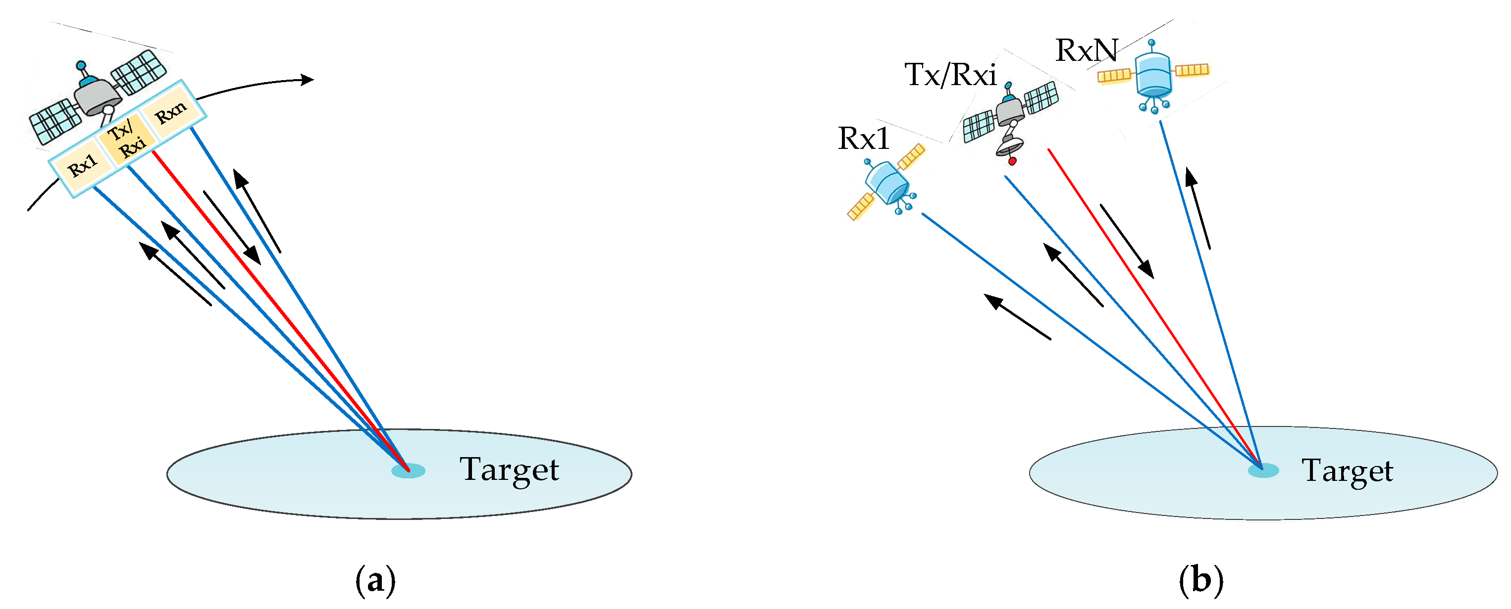
In most spaceborne DPCMAB SAR systems, one antenna is used to transmit radar signal, while multiple antennas/sub-antennas simultaneously receive its corresponding reflected echoes from the targets. This working scheme can be implemented in both a monostatic SAR system and a distributed SAR system, as shown in Figure 1. Multiple antennas/sub-antennas receive reflected echoes in each pulse repetition interval (PRI), which reduces the desired PRF and results in an expansion of the imaged swath [15]. As a result, the azimuth resolution can be improved while the swath width keeps constant, or the PRF can be reduced to obtain a wider swath without increasing azimuth ambiguities and reducing the azimuth resolution [16,17]. In the monostatic DPCMAB SAR system, the large receive antenna is evenly divided into multiple sub-apertures, as shown in Figure 1a, and the distance between adjacent receiving sub-apertures is about several meters. In the distributed DPCMAB SAR system, multiple SAR micro-satellites are used to receive reflected radar echoes, while the distance between two satellites is around hundreds of meters, as shown in Figure 1b. Besides improving the HRWS im-aging capacity, the distributed SAR system can increase the flexibility and reliability, greatly improve the satellite operation life, and reduce the operational cost [18]. No matter how DPCMAB SAR works, azimuth multichannel reconstruction is usually required before the imaging process as improper PRF adoption leads to azimuth non-uniform sampling [19,20].
Up to now, research on azimuth multichannel reconstruction has been focused on multichannel echo signal based on the conventional hyperbolic range equation (CHRE) model [19], which is derived from the airborne SAR geometry [21]. Because the azimuth phase error of the cubic term increases with the synthetic aperture acquisition time, fitting errors cannot be ignored in high-resolution squinted SAR [22]. In order to deal with the obvious increased fitting errors, an improved range model named advanced hyperbolic range equation (AHRE) was proposed in [23], in which an additional linear coefficient is added to the CHRE model. Range equation based on higher-order polynomials is also widely selected in high-resolution imaging, such as fourth-order range equation (FORE) [24], but the accuracy of this method is limited to the finite terms contained in the expression [25,26,27]. Although the FORE model has higher fitting accuracy, the AHRE model is selected due to its adequate accuracy in azimuth multichannel reconstruction.
In this study, the azimuth multichannel echo model based on AHRE was established and simulation experiments of azimuth multichannel raw data handled by the conventional azimuth multichannel reconstruction algorithm were carried out and analyzed. The azimuth time-varying phase error between azimuth channels based on AHRE will result in false targets in azimuth, especially for the distributed DPCMAB SAR system. In addition to the azimuth time-varying phase error, additional Doppler spectrum shift and extended Doppler bandwidth caused by the azimuth squint angle should be considered during azimuth multichannel reconstruction [28,29,30]. In order to deal with the problems of azimuth time-varying phase error and extended Doppler bandwidth in azimuth multichannel raw data based on the AHRE model, an improved azimuth multichannel reconstruction method is proposed in this paper. First, the time-varying phase errors between azimuth channels were compensated to avoid false targets in azimuth due to multichannel mismatch. Then, the range frequency dependent de-skewing function was derived to remove the two-dimensional (2D) spectrum tilt to avoid azimuth under-sampling before multichannel reconstruction and combination. Next, azimuth multichannel data were reconstructed according to the azimuth multichannel impulse response based on AHRE. Finally, the range frequency dependent re-skewing function and azimuth up-sampling were introduced to recover the tilted 2D spectrum. Consequently, the resulting equivalent single channel signal could be focused using the classical SAR imaging algorithms.
The rest of the paper is organized as follows. The azimuth multichannel signal model based on AHRE is derived and the azimuth time-varying phase error between azimuth channels is analyzed in Section 2. The improved azimuth reconstruction method based on AHRE is proposed in Section 3. Simulation experiments carried out on both point and distributed targets to validate the proposed azimuth multichannel reconstruction method is described in Section 4. Finally, the paper is concluded in Section 5.
2. Geometric Model and Slant Range Analysis
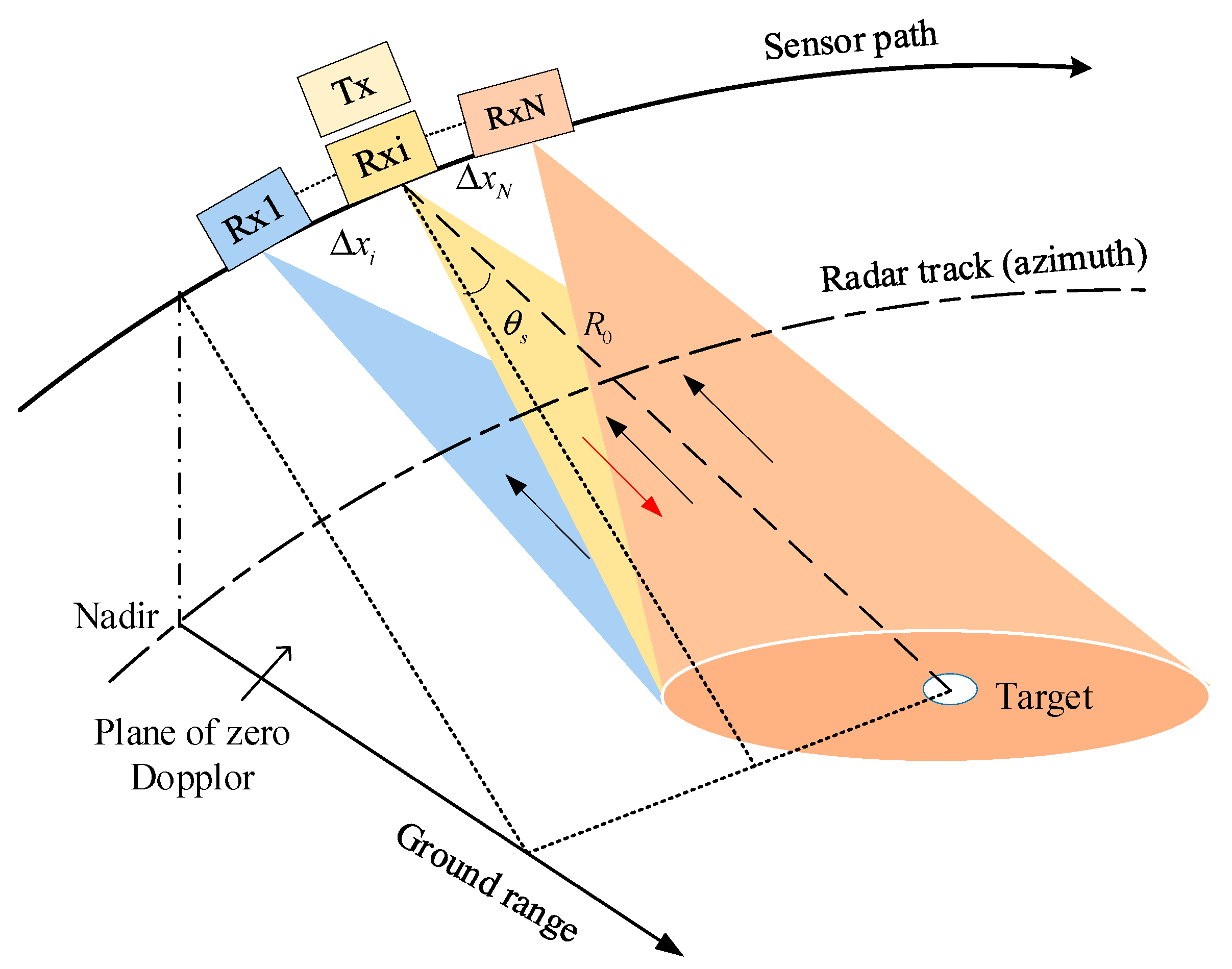
The imaging geometry of spaceborne azimuth multichannel squinted SAR is illustrated in Figure 2. One transmitting antenna Tx transmits radar signals, and all receiving sub-antennas Rx in azimuth simultaneously receive echoes reflected from the imaged scene. All receiving sub-antennas are aligned in azimuth. The physical interval between the i-th receiving sub-antenna and the transmitting antenna is , and the number of receiving sub-antennas is N. When the zero Doppler line crosses the target, the distance from radar to the target is denoted by the range of closest approach . The squint angle is the angle that the slant range vector makes with the plane of zero Doppler, as shown in Figure 2, which is an important component in the description of the azimuth beam pointing direction.
With increased geometric azimuth resolution and squint angle, the precision of the traditional CHRE model in spaceborne SAR is not sufficient. Therefore, the additional linear coefficient is introduced to form the AHRE model and improve the accuracy of the instantaneous range history between the radar and the target. This can deal with the problem of residual cubic phase error increasing with the synthetic aperture time. In the spaceborne single channel SAR system, the two-way instantaneous slant range based on the AHRE model is expressed as follows:
with
where t represents the azimuth time, is the equivalent squint angle, is the equivalent radar platform speed, is the radar wavelength, is the Doppler centroid frequency, is the slant range of the beam center crossing time, is the linear azimuth frequency modulation (FM) rate, and is the quadratic azimuth FM rate [27]. The third-order Taylor expansion of the single channel signal’s two-way instantaneous range is rewritten as follows:
In the spaceborne multichannel squinted SAR system shown in Figure 2, the two-way instantaneous range between the target and the i-th receiving antenna in azimuth is expressed as follows:
Taking the third-order Taylor expansion, the two-way instantaneous range is rewritten as follows:
Compared with the single-channel signal’s two-way instantaneous range history in (3), can be rewritten as follows:
with
The additional constant term is generated by the separation of receivers and transmitter can be processed in the derivation process of the reconstruction filter, while the influence of the azimuth time-varying range offset should be considered during azimuth multichannel reconstruction and focusing. The time-varying phase error between different azimuth channels due to the time-varying range offset is expressed as follows:
Generally speaking, the maximum receiving interval in a spaceborne monostatic DPCMAB SAR system is around several meters, while the minimum receiving interval in the distributed DPCMAB SAR system is around several hundred meters. The intervals between the transmitting and receiving antennas in the distributed DPCMAB SAR system and in the monostatic DPCMAB SAR system are usually less than 1000 and 10 m, respectively [17]. In order to analyze the influence of the time-varying phase error between azimuth channels, the following comparative analysis is mainly based on the two sets of simulation parameters with receiving intervals of 1000 m in the distributed system and 10 m in the single platform system.
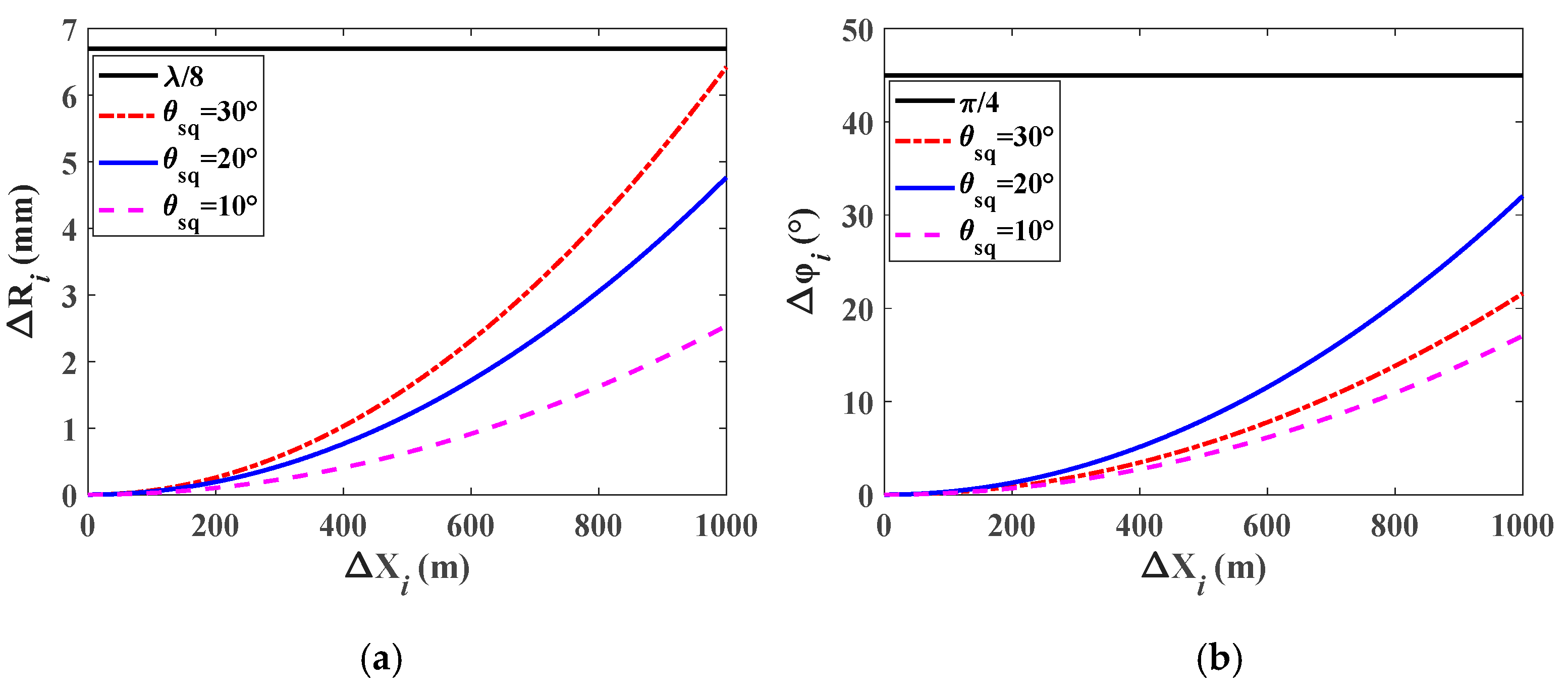
Using the simulation parameters of Table 1, the time-varying slant range error and the time-varying phase error were calculated by taking the squint angle and the maximum receiving distance as variables. The variations of the time-varying slant range term and the time-varying phase error with the distance between the transmitter and the receiver of each channel from 0 to 1000 m are shown in Figure 3. The time-varying phase error is less than , that is to say, the effect of the phase error on azimuth focusing can be ignored. However, as shown in Figure 3b, the phase error values will reach more than 40° when and . This phase mismatch in azimuth multichannel SAR is unacceptable during azimuth multichannel reconstruction and focusing because the unwanted false targets are very sensitive to the imbalance phase error between azimuth channels [19].
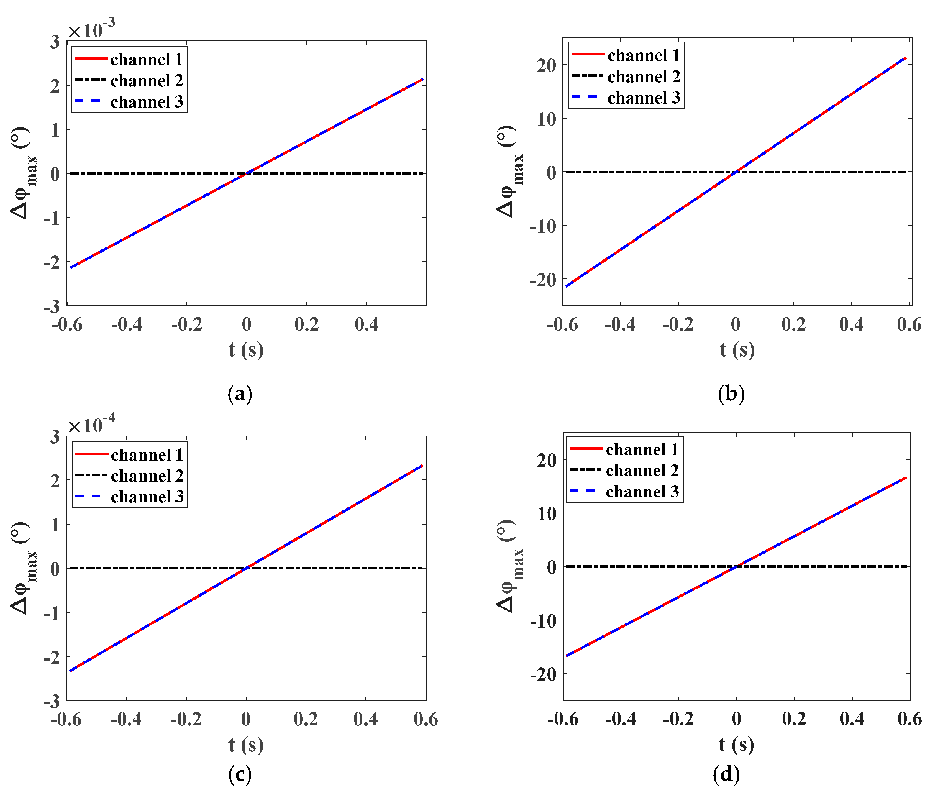
With the squint angle of 20°, the synthetic aperture time was calculated as 1.17 s according to the simulation parameters listed in Table 1. Taking the middle receive antenna as the reference channel, Figure 4 shows the time-varying phase error during the whole synthetic aperture interval in different cases. As shown in Figure 4a,b, the maximum time-varying phase error in the monostatic DPCMAB SAR system is very small and can be ignored, while the imbalance phase error will reach more than 20° and cannot be ignored in the distributed spaceborne SAR system. In the following simulation experiments, the maximum physical intervals between the receive antenna center and the transmit antenna center in the single-platform and distributed SAR systems were allocated as 3.33 and 885 m, respectively, while their maximum phase errors during the whole synthetic aperture interval are shown in Figure 4c,d.
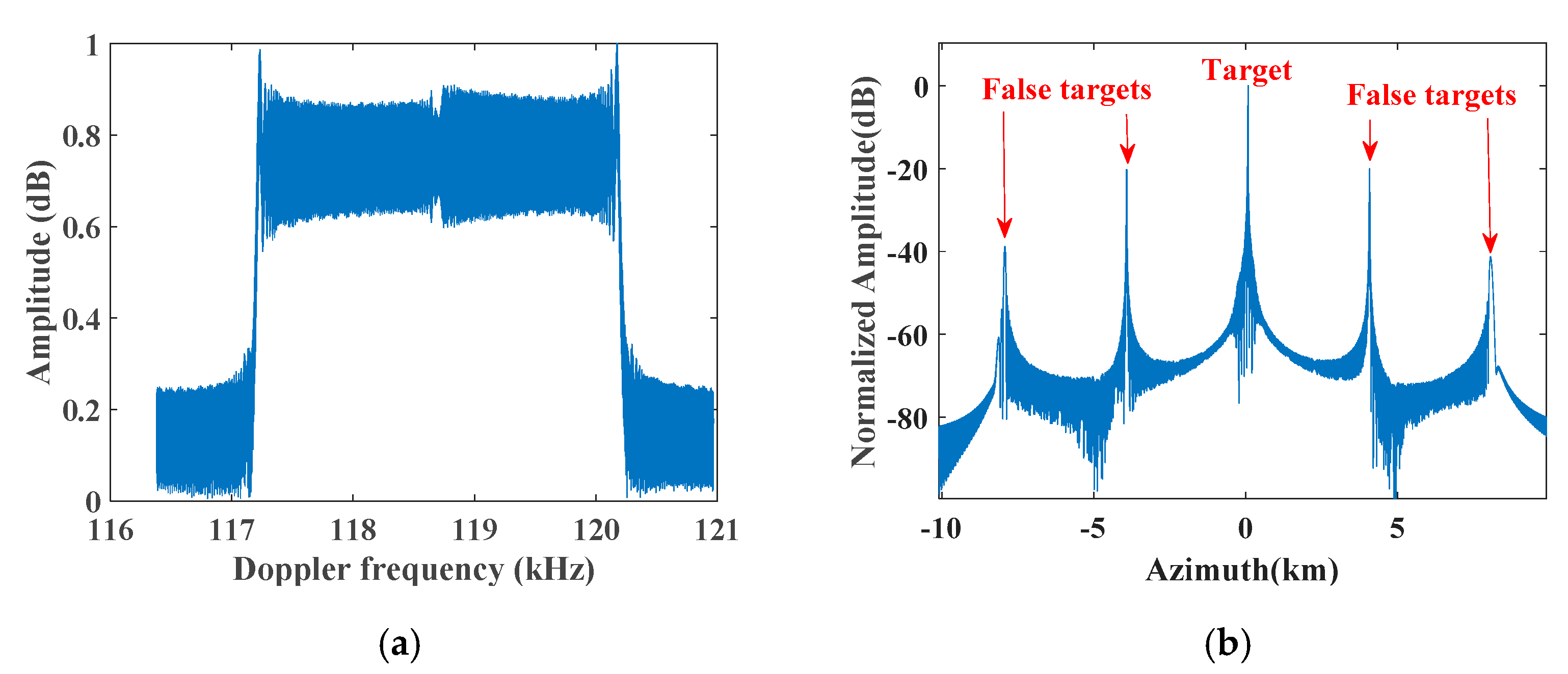
To demonstrate the impact of the time-varying phase error on azimuth multichannel reconstruction and azimuth focusing, one dimensional (1D) traditional azimuth multichannel reconstruction simulation experiments were carried out in both monostatic and distributed DPCMAB SAR systems, and their corresponding simulation results are shown in Figure 5 and Figure 6, respectively. The conventional azimuth multichannel reconstruction means that the signal based on the CHRE model is directly passed through the reconstruction filter generated by the relationship between multichannel and single channel signals for signal reconstruction without removing the azimuth time-varying phase error, the de-skewing and re-skewing processes before and after reconstruction. In a monostatic DPCMAB SAR system, the multichannel echoes can be well reconstructed using the traditional azimuth multichannel reconstruction method, as shown in Figure 5c, and ambiguous false targets in the azimuth compression result are well suppressed, as shown in Figure 5d. However, in a distributed DPCMAB SAR system, the spectrum cannot be well reconstructed due to the azimuth time-varying phase errors between azimuth channels, as shown in Figure 6b, and false targets still occur in the focused azimuth impulse response, as shown in Figure 6d. Compared with the focusing result without azimuth multichannel reconstruction in Figure 6c, false targets are only suppressed about 10 dB. Therefore, the time-varying phase errors between azimuth channels in the monostatic DPCMAB cannot be neglected during azimuth multichannel reconstruction, while these phase errors must be compensated in the distributed SAR system; otherwise, false targets will occur in the final azimuth compression result.
3. Azimuth Multichannel Reconstruction Based on AHRE
According to the above analysis and simulation results, the time-varying phase error in the monostatic DPCMAB SAR system is so small that its corresponding influence on azimuth multichannel reconstruction can be ignored. However, in the distributed DPCMAB SAR system, the maximum time-varying phase error will reach more than 10°, especially for the large squint case, and this error must be considered during azimuth multichannel reconstruction; otherwise, the Doppler spectrum will not be well recovered and pairs of false targets with high level will occur in the final azimuth focusing result. Therefore, especially in the distributed DPCMAB SAR system with the squint angle, azimuth multichannel reconstruction should be modified to handle the raw data to improve the focusing performance.
3.1. One-Dimensional Azimuth Multichannel Reconstruction
The single channel azimuth signal and the multichannel azimuth signal based on AHRE are described as follows:
Substituting (6) into (11), the multichannel azimuth signal can be rewritten as follows:
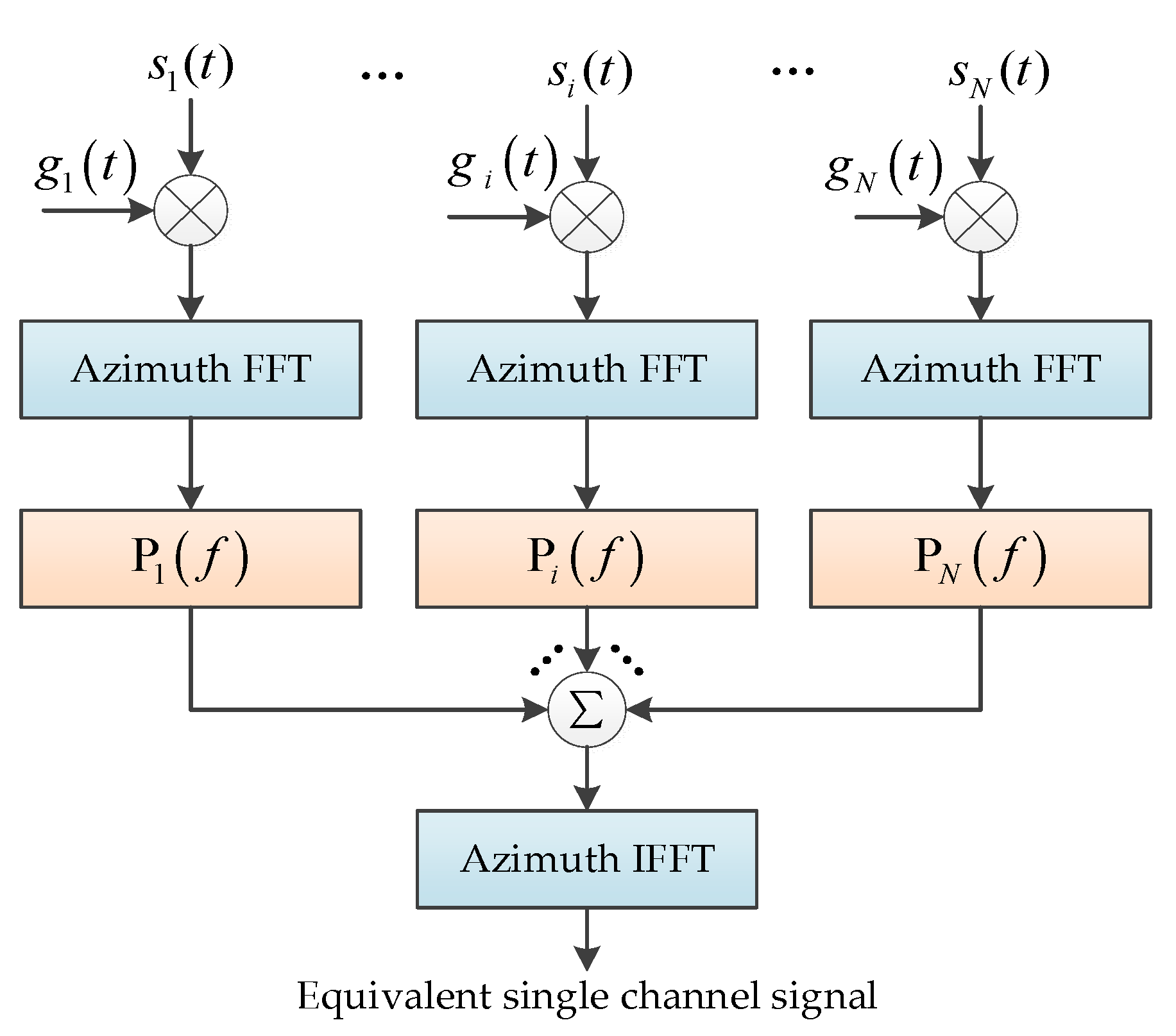
Compared with the multichannel azimuth impulse response based on CHRE, the major difference is the third term of additional time-varying phase error. After removing the additional time-varying phase error in each azimuth channel, the azimuth multichannel reconstruction matrix can be easily obtained from the azimuth time offset and the constant phase in (12). The flow chart of the modified 1D azimuth multichannel reconstruction method based on AHRE is shown in Figure 7.
To remove the azimuth time-varying phase error, the phase compensation function is multiplied and expressed as follows:
According to equation (12), the multichannel response for the i-th channel is as follows:
The impulse response in the frequency domain is written as follows:
where represents the Doppler frequency. Therefore, the azimuth multichannel system matrix based on AHRE is obtained, and the reconstruction filter matrix is derived from the inversion of the matrix as follows:
Consequently, azimuth multichannel echoes are processed by the reconstruction matrix , and the equivalent unambiguous single channel signal is obtained after raw data combination and inverse fast Fourier transform (IFFT). It is worth noting that the large maximum distance of receiver and transmitter in the distributed DPCMAB SAR system may lead to coincidence of sampling points, which means the system filter cannot be full of rank and the inverse matrix cannot be obtained [16]. In order to ensure the reversibility of the matrix , samples with different receiving channels must not coincide in space, especially for the distributed DPCMAB SAR system.
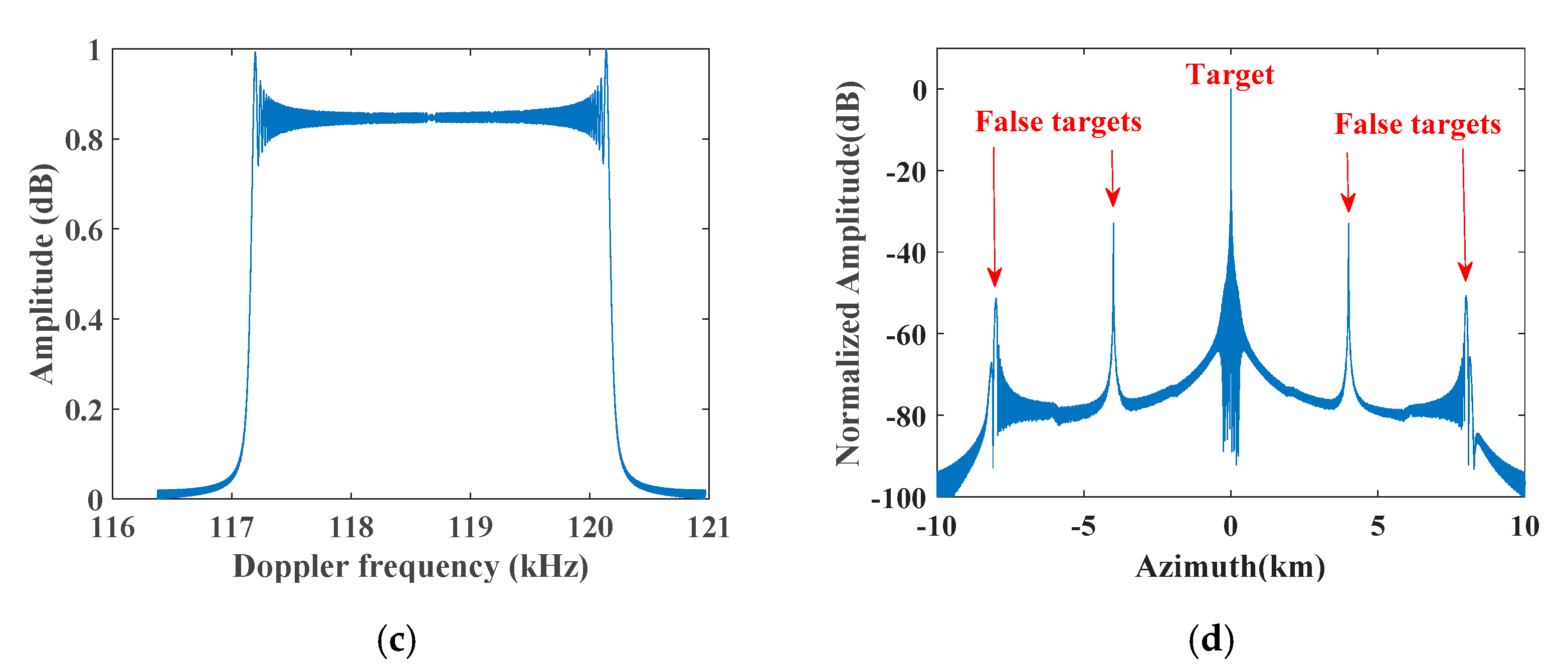
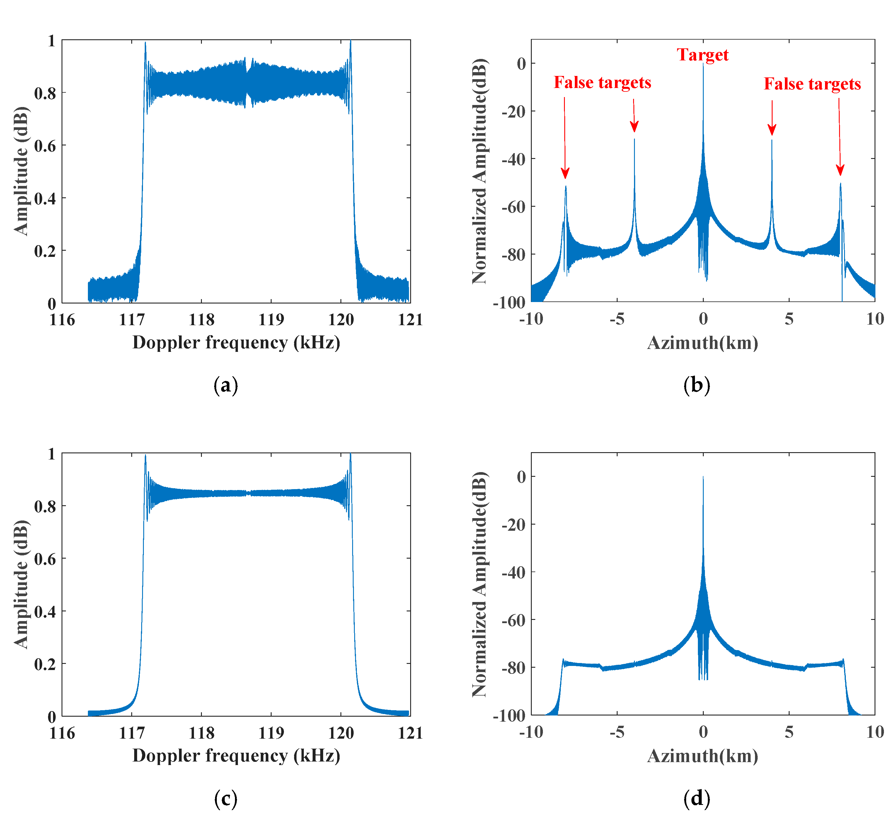
With the simulation parameters listed in Table 1, Figure 8 shows the results of processing the time-varying phase error before using the improved azimuth multichannel reconstruction filter to reconstruct nonuniform sampling signal. The distance between adjacent receive antennas were 885 and 970 m. Due to not removing the azimuth time-varying channel phase error before multichannel reconstruction filtering based on the AHRE model, the Doppler spectrum was not well reconstructed and a pair of false targets occurred in the corresponding azimuth compression result, as shown in Figure 8a,b. However, after processing time-varying phase error and reconstructing the nonuniform signal using the modified reconstruction filter based on the AHRE model, the Doppler spectrum is well reconstructed and false targets disappeared, as shown in Figure 8c,d.
3.2. Two-Dimensional Azimuth Multichannel Reconstruction
The single-channel impulse response in the range frequency azimuth time domain is written as follows [31]:
where is the complex constant, the range pulse envelope is the rectangular window function, the azimuth antenna pattern is a function of azimuth time , is the range frequency, is the azimuth time, is the range modulated frequency rate, and is the speed of light. The instantaneous Doppler frequency of the SAR data based on AHRE is related to the squint angle and the additional linear coefficient in AHRE and expressed as follows:
where indicates the target azimuth position related to the azimuth beam pointing direction, and is the exploited beam width for azimuth focusing. Consequently, taking account of the extended Doppler bandwidth due to the squint case, the total processed Doppler bandwidth in the squint case is as follows:
where is the transmitted pulse bandwidth, is the Doppler bandwidth corresponding to the azimuth beam width, is the Doppler bandwidth related to the squint angle [32], and is the Doppler bandwidth related to the additional linear coefficient in the AHRE model.
In the spaceborne SAR system design, to obtain wide swath coverage and suppress range ambiguities, the effective azimuth sampling frequency is only a little higher than the azimuth beam bandwidth, and the azimuth over sampling rate is usually 1.3–1.5. With the simulation parameters listed in Table 1 and the squint angle of 25°. Figure 9 shows the scale coefficients between the extended Doppler bandwidth and the azimuth beam bandwidth. As can be seen, the extended Doppler bandwidth related to both the equivalent squint angle and the additional linear coefficient exceeds the azimuth beam width when the transmitted pulse bandwidth is more than 200 MHz. In this study, the transmitted pulse bandwidth was 200 MHz, the total Doppler bandwidth was 8124.6 Hz, and the azimuth effective sampling frequency was only 4590 Hz. Therefore, the Doppler spectrum aliasing problem due to the squint case would need to be considered during azimuth multichannel reconstruction.
As the shape of the 2D spectrum in the squint case is parallelogram, as shown in Figure 10a, de-skewing operation can reduce the total bandwidth of the raw data, as shown in Figure 10b. Therefore, before azimuth multichannel reconstruction, de-skewing was operated in each azimuth channel, and azimuth multichannel reconstruction was operated in the 2D frequency domain. The major problem of azimuth multichannel reconstruction in the 2D frequency domain is neglecting the range-variant phase error caused by the strong coupling between Doppler and range frequencies, and this error becomes more obvious in the distributed DPCMAB SAR system. To improve the performances of azimuth multichannel reconstruction and the following 2D focusing, the range-variant phase error should be compensated during multichannel reconstruction.
Neglecting the unimportant range frequency modulation, constant, and envelop terms, the azimuth multichannel impulse response of the channel in the range frequency azimuth time domain is rewritten as follows:
The first phase term is for azimuth multichannel reconstruction, while the second one should be removed before reconstruction, which can be implemented in the 2D time domain. Furthermore, different azimuth time offsets in different azimuth channels must be considered during the de-skewing operation in each azimuth channel. As the azimuth multichannel reconstruction is mainly operated in the 2D frequency domain, the residual range-variant phase error also needs to be compensated in the range Doppler domain. The flowchart of the proposed azimuth multichannel reconstruction method is shown in Figure 11, which includes steps of azimuth time-varying phase removing, 2D spectrum de-skewing, azimuth multichannel reconstruction in the 2D frequency domain, range-variant reconstruction phase error compensation, and 2D spectrum re-skewing.
The time-varying phase error compensation in each azimuth channel is implemented in the 2D time domain, and the compensation function is as follows:
After eliminating the time-varying phase error, the de-skewing operation is operated in the range frequency azimuth time domain. To keep the relationship between the multichannel and the single channel responses, different azimuth time offsets must be considered during de-skewing, and the de-skewing function is expressed as follows:
As the de-skewing operation in each channel is implemented in the range frequency azimuth time domain, the resulting azimuth multichannel reconstruction can be only handled in the 2D frequency domain. Consequently, the reference slant range should be selected in the following multichannel reconstruction, and usually the slant range of the imaged swath center is used to minimize the reconstruction error. The azimuth multichannel reconstruction matrix is obtained by the inverse of the azimuth multichannel system matrix as follows:
The azimuth multichannel system matrix has elements. According to the relationship between the single channel signal and the processed multichannel signal in (20), the element in the n-th row and i-th column of the matrix is as follows:
In order to completely reconstruct the unaliased 2D spectrum, the signal is reconstructed into N sub-band within the range of , and is the Doppler centroid of the whole raw data.
Significantly, the range history deviation is large for the large maximum distance of receiver and transmitter in the distributed SAR system, which has been proven to cause significant reconstruction mismatch and increase azimuth ambiguities and coincidence of the sampling points. The signal after reconstruction filter in channel can be multiplied with the differential reconstruction filter to process the residual error of the reconstruction filter, update every range bin, and match the range cell migration of the data [33].
with
where is the phase of the differential reconstruction filter, is the phase of the reconstruction filters , and is a polychromatic residual phase [33].
The re-skewing process is also needed to recover the original Doppler history of the signal, and the re-skewing function is expressed as follows:
Finally, after range Fourier transform, the equivalent single channel raw data with sufficient azimuth sampling is obtained from the azimuth multichannel raw data.
4. Simulation Experiments
This section discusses the simulation experiments carried out on both point and distributed targets to validate the proposed multichannel reconstruction approach using the simulation parameters of Table 1. According to the above analysis and simulation results, the impact of the azimuth time-varying phase errors between azimuth channels on multichannel reconstruction in a monostatic DPCMAB SAR system is very limited and can be neglected, while the impact in the distributed DPCMAB SAR system must be considered. Therefore, only simulation experiments in the distributed SAR system were carried out. The distance between adjacent receive antennas in azimuth are 885 and 970 m.
4.1. Simulation Experiments on Point Targets
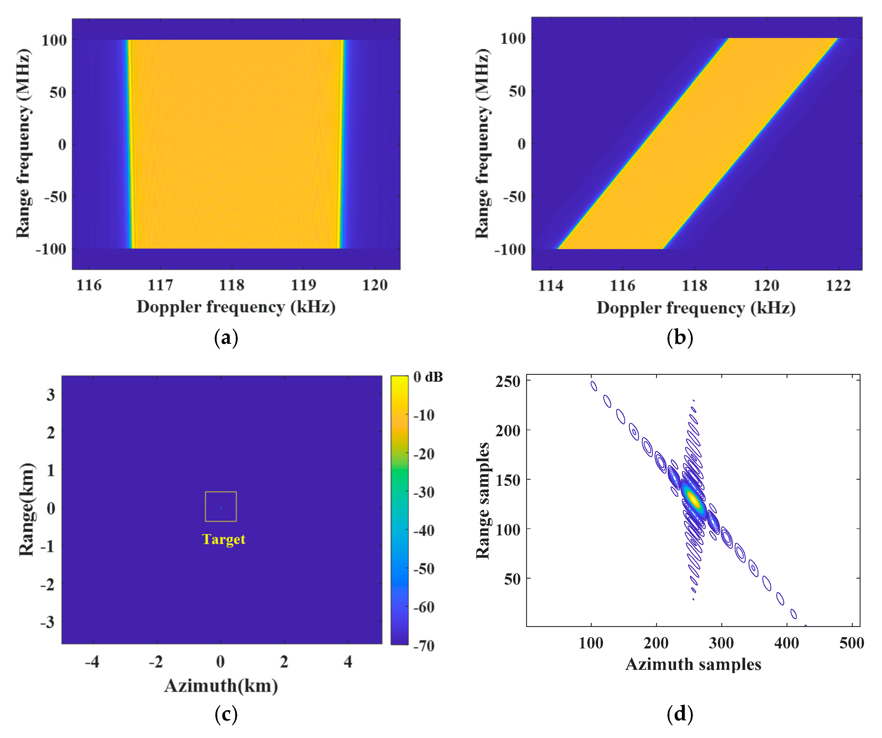
Figure 12 shows simulation results of the point target in the swath center handled by the multichannel reconstruction approach based on CHRE, while Figure 13 shows results of the point target in the swath center handled by the improved processor based on AHRE. As shown in Figure 12b, the raw data in each azimuth channel is aliased in the Doppler domain. The 2D spectrum is well reconstructed after de-skewing and modified azimuth multichannel reconstruction based on AHRE, as shown in Figure 13c. After azimuth up-sampling and re-skewing, the original 2D spectrum is well recovered and sufficiently sampled, as shown in Figure 13d, and the improved sampling frequency was 9.7495 kHz. The focusing result and contour plots of the target with the conventional imaging processor based on CHRE are shown in Figure 12e,f, respectively. As can be seen, the results showed negative focusing behavior and with a pair of false targets.
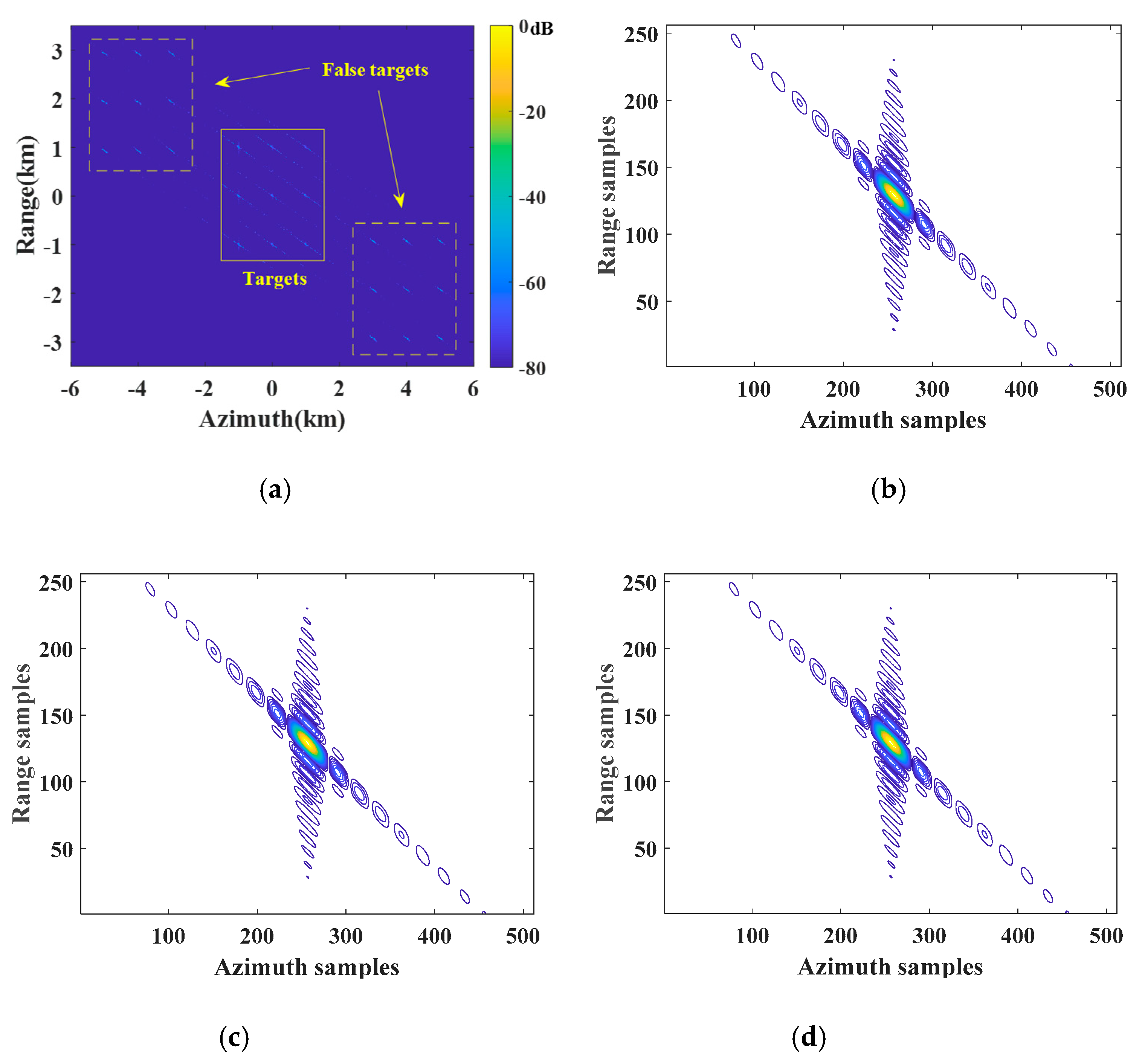
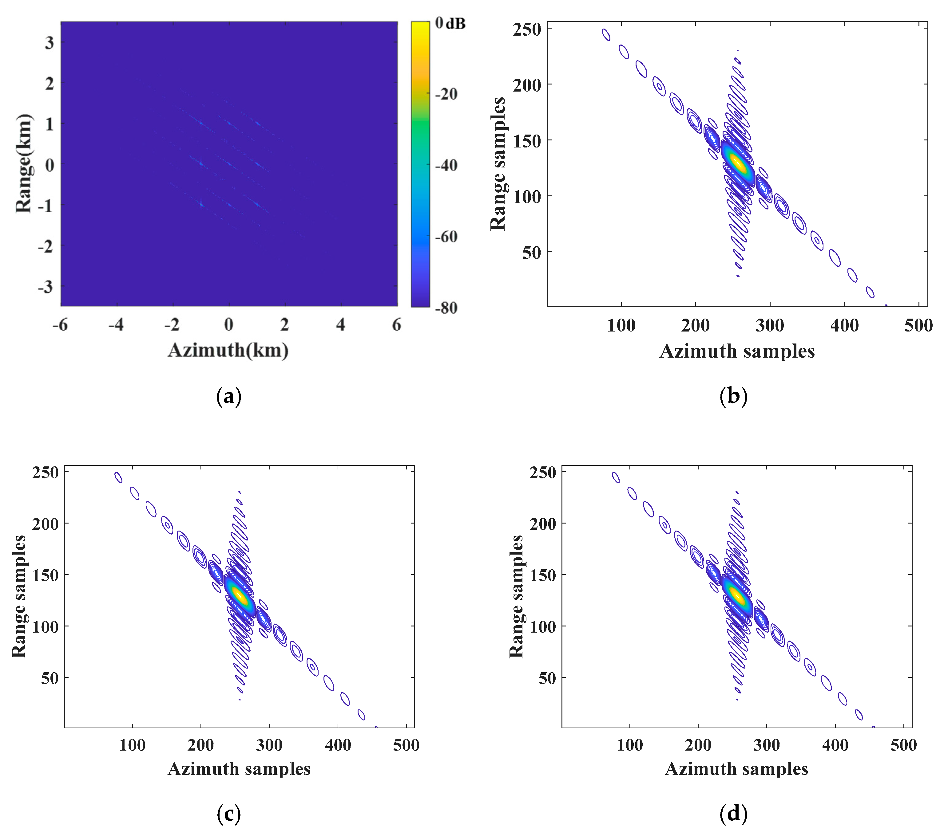
Furthermore, a simulation experiment is carried out on the designed scene with nine point targets. The arrangement of the designed nine point targets is shown in Figure 14. Figure 15 shows the simulation results of the conventional azimuth multichannel reconstruction method, while Figure 16 shows the results of the proposed azimuth multichannel reconstruction method in Figure 11. Comparing the results of the two methods, false targets are well suppressed in the proposed method. The measured imaging parameters, including resolution (Res.); peak sidelobe ratio (PSLR), which is the ratio between the height of the largest sidelobe and the height of the main lobe; integrated sidelobe ratio (ISLR), which is the ratio between the total power of the sidelobes and the main lobe power; and maximum false target amplitude (MFTA), are summarized in Table 2. The results in Figure 15, Figure 16, and Table 2 show the superiority of the proposed azimuth multichannel reconstruction method based on AHRE.
4.2. Simulation Experiments of Distributed Scene targets
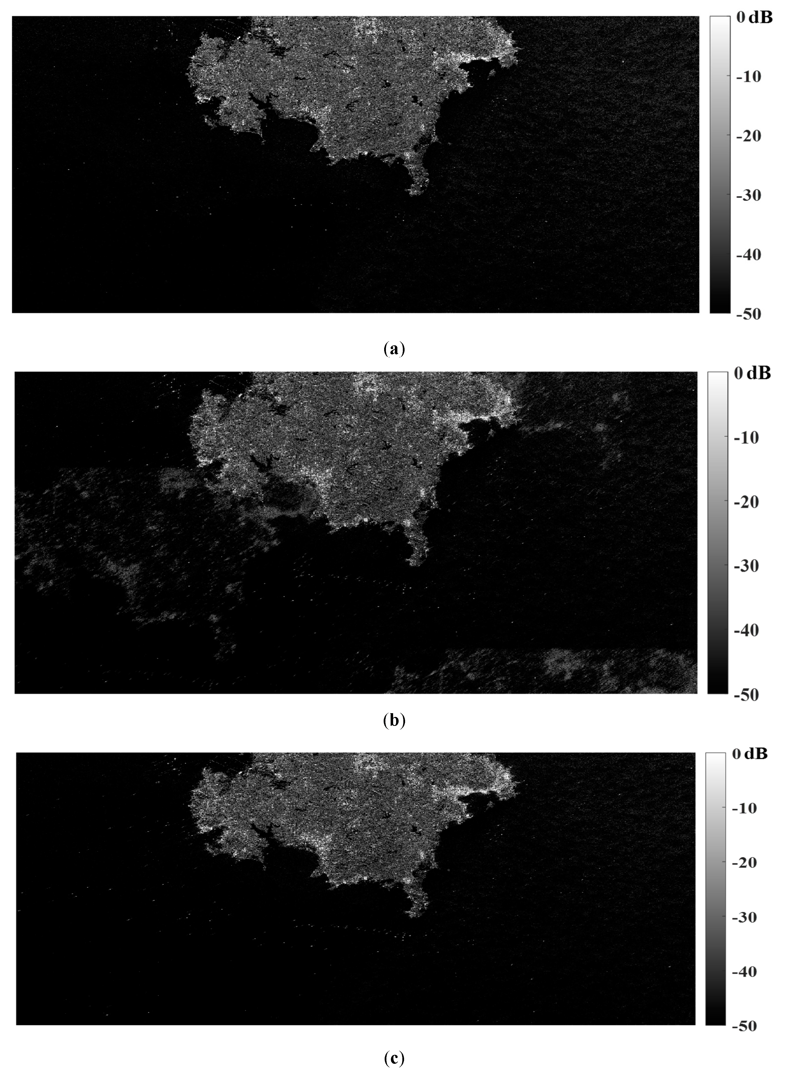
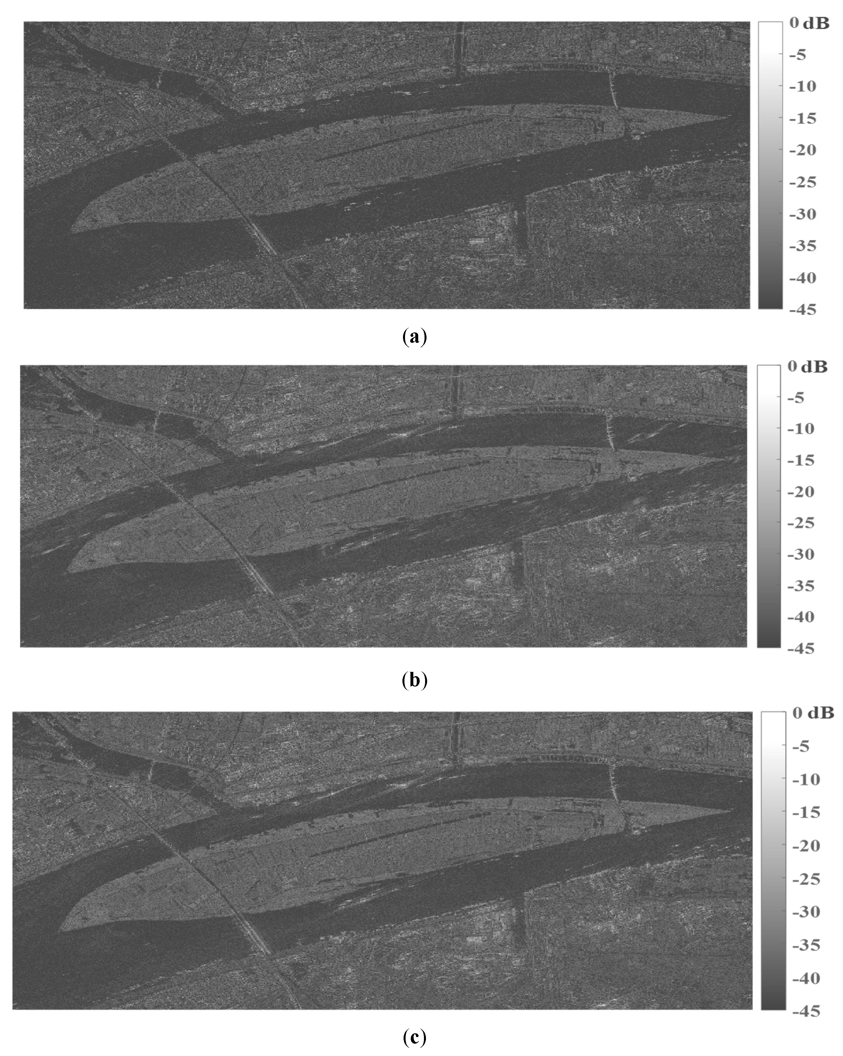
In order to further verify the superiority of the proposed 2D multichannel reconstruction method based on AHRE, a focused Sentinel-1 single look complex (SLC) SAR image of Shandong Peninsula and a Gaofen-3 (GF-3) SLC SAR image of Wuhan city in Hubei province are selected for azimuth multichannel echo simulation, reconstruction, and imaging, as shown in Figure 17a and Figure 18a. Figure 17b and Figure 18b show the imaging results processed by the conventional azimuth multichannel reconstruction method based on CHRE, in which false targets occurred in the focused SAR images. With the proposed azimuth multichannel reconstruction method based on AHRE, false targets are well suppressed and could not even be observed, as shown in Figure 17c and Figure 18c. Comparing the simulation results in Figure 17 and Figure 18, the false target suppression effect can be more easily observed in Figure 17 as the false targets of the island can be obviously noticed in the sea area, as show in Figure 17b. Simulation results on distributed scene further validated the false targets suppression effect of the proposed azimuth multichannel reconstruction method.
5. Conclusions
The AHRE model can provide more accurate range history from the radar to the imaged target, which is more suitable for high-resolution imaging mode and squint observation cases. In this study, a multichannel signal model based on AHRE was established for the DPCMAB SAR system. Compared to the signal model based on CHRE, the major difference is the additional azimuth time-varying phase error between azimuth channels. The maximum value of the azimuth time-varying phase error will reach more than 10° in a distributed DPCMAB SAR system with a certain squint angle, which will result in a pair of false targets in the final azimuth focusing result because false targets are sensitive to channel phase imbalance in the DPCMAB SAR system. Furthermore, the additional Doppler bandwidth related to the equivalent squint angle and the additional linear coefficient in AHRE extends the total Doppler bandwidth and results in Doppler spectrum aliasing. To resolve the Doppler aliasing problem, de-skewing was introduced, and the azimuth multichannel was operated in 2D frequency domain. Furthermore, the excessive reconstruction residual error resulting from the large maximum receiving interval in the distributed DPCMAB SAR system was compensated in the range Doppler domain. Simulation results on both point and distributed targets validated the proposed azimuth multichannel reconstruction approach based on AHRE.
Author Contributions
Conceptualization, W.X.; methodology, W.X.; software, W.X. and R.L.; validation, P.H. and W.X.; formal analysis, R.L.; investigation, W.X. and R.L.; resources, W.X., C.F. and W.T.; data curation, R.L.; writing—original draft preparation, W.X. and R.L.; writing—review and editing, W.X. and P.H.; visualization, W.T.; supervision, W.T and Y.Q.; project administration, P.H. and W.T.; funding acquisition, W.X. and C.F. All authors have read and agreed to the published version of the manuscript.
Funding
This research was funded by the National Natural Science Foundation of China, grant numbers 62071258, 61971246, and 61631011; in part by the Natural Science Foundation of Inner Mongolia, grant numbers 2020ZD18 and 2019MS04004; and in part by the National Defense Key Laboratory Fund Project under grant 6142216190209.
Institutional Review Board Statement
Not applicable.
Informed Consent Statement
Not applicable.
Data Availability Statement
Not applicable.
Conflicts of Interest
The authors declare no conflict of interest.
References
- Ma, X.; Sun, Z.; Dong, Z.; Huang, H. Azimuth ambiguity of multichannel SAR. In Proceedings of the 2012 IEEE International Geoscience and Remote Sensing Symposium, Munich, Germany, 22–27 July 2012; pp. 3807–3810. [Google Scholar]
- Suess, M.; Grafmueller, B.; Zahn, R. A novel high resolution, wide swath SAR system. In IGARSS 2001 Scanning the Present and Resolving the Future, Proceedings of the IEEE 2001 International Geoscience and Remote Sensing Symposium, Sydney, Australia, 9–13 July 2002; IEEE: Manhattan, NY, USA, 2001; Volume 3, pp. 1013–1015. [Google Scholar]
- Yang, J.; Qiu, X.; Zhong, L.; Shang, M.; Ding, C. A simultaneous imaging scheme of stationary clutter and moving targets for maritime scenarios with the first Chinese dual-channel spaceborne SAR sensor. Remote. Sens. 2019, 11, 2275. [Google Scholar] [CrossRef] [Green Version]
- Wang, W.-Q.; Peng, Q.; Cai, J. Digital beamforming for near-space wide-swath SAR imaging. In Proceedings of the 8th International Symposium on Antennas, Propagation and EM Theory, Kunming, China, 2–5 November 2008; pp. 1270–1273. [Google Scholar]
- Wang, W.-Q.; Cai, J.; Peng, Q. Conceptual design of near-space synthetic aperture radar for high-resolution and wide-swath imaging. Aerosp. Sci. Technol. 2009, 13, 340–347. [Google Scholar] [CrossRef]
- Wang, W.-Q. Near-space wide-swath radar imaging with multi-aperture antenna. IEEE Antennas Wirel. Propag. Lett. 2009, 8, 461–464. [Google Scholar] [CrossRef]
- Xu, W.; Deng, Y. Multichannel SAR with reflector antenna for high-resolution wide-swath imaging. IEEE Antennas Wirel. Propag. Lett. 2010, 9, 1123–1126. [Google Scholar] [CrossRef]
- Lin, D.; Peiguo, L. Noise-modulated oppressive jamming for DPC MAB SAR. In Proceedings of the 2008 International Conference on Microwave and Millimeter Wave Technology, Nanjing, China, 21–24 April 2008; pp. 2040–2042. [Google Scholar]
- Zou, Q.; Xin, Q.; Cheng, P. Non-uniformly sampled signal reconstruction of DPC-MAB FMCW SAR based on fractional fourier transform. In Proceedings of the IEEE International Geoscience and Remote Sensing Symposium, Milan, Italy, 26–31 July 2015; pp. 4578–4581. [Google Scholar]
- Gebert, N.; Krieger, G.; Moreira, A. SAR signal reconstruction from non-uniform displaced phase centre sampling in the presence of perturbations. In Proceedings of the IEEE International Geoscience and Remote Sensing Symposium, Seoul, Korea, 29 July 2005; Volume 2, pp. 1034–1037. [Google Scholar]
- Pitz, W.; Miller, D. The TerraSAR-X satellite. IEEE Trans. Geosci. Remote. Sens. 2010, 48, 615–622. [Google Scholar] [CrossRef]
- Cerutti-Maori, D.; Sikaneta, I.; Gierull, C.H. Optimum SAR/GMTI processing and its application to the radar satellite RADARSAT-2 for traffic monitoring. IEEE Trans. Geosci. Remote. Sens. 2012, 50, 3868–3881. [Google Scholar] [CrossRef]
- Jiang, S.; Qiu, X.; Han, B.; Sun, J.; Ding, C. Error source analysis and correction of GF-3 polarimetric data. Remote. Sens. 2018, 10, 1685. [Google Scholar] [CrossRef] [Green Version]
- Zhong, L.; Qiu, X.; Han, B.; Hu, Y. An improved descalloping method combined with imaging parameters for GaoFen-3 ScanSAR. Remote. Sens. 2020, 12, 822. [Google Scholar] [CrossRef] [Green Version]
- Brown, J. Multichannel sampling of low-pass signals. IEEE Trans. Circuits Syst. 1981, 28, 101–106. [Google Scholar] [CrossRef]
- Krieger, G.; Gebert, N.; Moreira, A. Unambiguous SAR signal reconstruction from nonuniform displaced phase center sampling. IEEE Geosci. Remote. Sens. Lett. 2004, 1, 260–264. [Google Scholar] [CrossRef] [Green Version]
- Goodman, N.A.; Sih Chung, L.; Rajakrishna, D.; Stiles, J.M. Processing of multiple-receiver spaceborne arrays for wide-area SAR. IEEE Transactions on Geoscience and Remote Sensing 2002, 40, 841–852. [Google Scholar] [CrossRef]
- Sakar, N.; Rodriguez-Cassola, M.; Prats-Iraola, P.; Reigber, A.; Moreira, A. Analysis of geometrical approximations in signal reconstruction methods for multistatic SAR constellations with large along-track baseline. IEEE Geosci. Remote. Sens. Lett. 2018, 15, 892–896. [Google Scholar] [CrossRef]
- Xu, W.; Wei, Z.; Huang, P.; Tan, W.; Liu, B.; Gao, Z.; Dong, Y. Azimuth multichannel reconstruction for moving targets in Geosynchronous Spaceborne–Airborne bistatic SAR. Remote. Sens. 2020, 12, 1703. [Google Scholar] [CrossRef]
- Gao, H.; Chen, J.; Quegan, S.; Yang, W.; Li, C. Parameter estimation and error calibration for multichannel beam-steering SAR systems. Remote. Sens. 2019, 11, 1415. [Google Scholar] [CrossRef] [Green Version]
- Moreira, A.; Huang, Y. Airborne SAR processing of highly squinted data using a chirp scaling approach with integrated motion compensation. IEEE Trans. Geosci. Remote. Sens. 1994, 32, 1029–1040. [Google Scholar] [CrossRef]
- Moreira, A.; Mittermayer, J.; Scheiber, R. Extended chirp scaling algorithm for air- and spaceborne SAR data processing in stripmap and ScanSAR imaging modes. IEEE Trans. Geosci. Remote. Sens. 1996, 34, 1123–1136. [Google Scholar] [CrossRef]
- Huang, L.; Qiu, X.; Hu, D.; Ding, C. Focusing of medium-earth-orbit SAR with advanced nonlinear chirp scaling algorithm. IEEE Trans. Geosci. Remote. Sens. 2010, 49, 500–508. [Google Scholar] [CrossRef]
- Eldhuset, K. A new fourth order SAR processing algorithm for very high resolution. In IGARSS ’98 Sensing and Managing the Environment, Proceedings of the IEEE International Geoscience and Remote Sensing, Seattle, WA, USA, 6–10 July 1998; IEEE: Manhattan, NY, USA, 1998; Volume 5, p. 2633. [Google Scholar]
- Eldhuset, K. A new fourth-order processing algorithm for spaceborne SAR. IEEE Trans. Aerosp. Electron. Syst. 1998, 34, 824–835. [Google Scholar] [CrossRef] [Green Version]
- Wu, X.; Zhang, S.; Xiao, B. An advanced range equation for geosynchronous SAR image formation. In Proceedings of the IET International Conference on Radar Systems, Glasgow, UK, 22–25 October 2012; pp. 1–4. [Google Scholar]
- Wu, X.; Zhang, S.; Li, J.; Cao, W. Geosynchronous SAR image formation based on advanced hyperbolic range equation. In Proceedings of the IEEE International Geoscience and Remote Sensing Symposium, Munich, Germany, 22–27 July 2012; pp. 4042–4045. [Google Scholar]
- Lijia, H.; Xiaolan, Q.; Donghui, H.; Chibiao, D. An advanced 2-D spectrum for high-resolution and MEO spaceborne SAR. In Proceedings of the 2nd Asian-Pacific Conference on Synthetic Aperture Radar, Shanxi, China, 26–30 October 2009; pp. 447–450. [Google Scholar]
- Yang, L.; Bi, G. SAR imaging method for high speed and maneuverability based on modified hyperbolic range equation. In Proceedings of the IET International Radar Conference 2013, Xi’an, China, 14–16 April 2013; pp. 1–6. [Google Scholar]
- Fan, W.; Zhang, M.; Li, J.; Wei, P. Modified range-doppler algorithm for high squint SAR echo processing. IEEE Geosci. Remote. Sens. Lett. 2018, 16, 422–426. [Google Scholar] [CrossRef]
- Huang, P.; Xu, W.; Li, S. Spaceborne squinted multichannel synthetic aperture radar data focusing. IET Radar Sonar Navig. 2014, 8, 1073–1080. [Google Scholar] [CrossRef]
- Sun, G.; Jiang, X.; Xing, M.; Qiao, Z.-J.; Wu, Y.; Bao, Z. Focus improvement of highly squinted data based on Azimuth nonlinear scaling. IEEE Trans. Geosci. Remote. Sens. 2011, 49, 2308–2322. [Google Scholar] [CrossRef]
- Sakar, N.; Rodriguez-Cassola, M.; Prats-Iraola, P.; Moreira, A. Azimuth reconstruction algorithm for multistatic SAR formations with large along-track baselines. IEEE Trans. Geosci. Remote. Sens. 2019, 58, 1931–1940. [Google Scholar] [CrossRef]
Figure 1.
Spaceborne DPCMAB SAR. (a) The monostatic SAR system; (b) the distributed SAR system.

Figure 2.
The observation geometry in spaceborne azimuth multichannel squinted SAR.

Figure 3.
Analysis of the time-varying term. (a) The time-varying slant range error produced by in different ; (b) the time-varying phase error Δφi produced by Δxi in different θsq.
Figure 3.
Analysis of the time-varying term. (a) The time-varying slant range error produced by in different ; (b) the time-varying phase error Δφi produced by Δxi in different θsq.

Figure 4.
Time-varying phase errors between azimuth channels in different DPCMAB systems. (a) In a monostatic system with azimuth aperture intervals of −10 and 10 m; (b) in a distributed satellite system with azimuth aperture intervals of −1 and 1 km; (c) in a monostatic system with azimuth aperture intervals of −3.33 and 3.33 m; (d) in a distributed satellite system with azimuth aperture intervals of 885 and 970 m.

Figure 5.
Azimuth multichannel reconstruction results in the monostatic DPCMAB SAR system. (a) Azimuth spectrum without azimuth multichannel reconstruction; (b) azimuth compression result without azimuth multichannel reconstruction; (c) azimuth spectrum after conventional azimuth multichannel reconstruction; (d) azimuth compression result after conventional azimuth multichannel reconstruction.

Figure 6.
Azimuth multichannel reconstruction results in a distributed DPCMAB SAR system. (a) Azimuth spectrum without azimuth multichannel reconstruction; (b) azimuth compression result without azimuth multichannel reconstruction; (c) azimuth spectrum after conventional azimuth multichannel reconstruction; (d) azimuth compression result after conventional azimuth multichannel reconstruction.


Figure 7.
Flowchart of the improved 1D azimuth multichannel reconstruction method.

Figure 8.
Azimuth multichannel reconstruction based on AHRE in a distributed DPCMAB SAR system. (a) Azimuth spectrum after conventional multichannel reconstruction; (b) azimuth compression result of (a); (c) azimuth spectrum after improved multichannel reconstruction; (d) azimuth compression result of (c).

Figure 9.
The extended Doppler bandwidth.

Figure 10.
2D frequency spectrum in the squint case. (a) 2D frequency spectrum before de-skewing; (b) 2D frequency spectrum after de-skewing.
Figure 10.
2D frequency spectrum in the squint case. (a) 2D frequency spectrum before de-skewing; (b) 2D frequency spectrum after de-skewing.

Figure 11.
Flowchart of the proposed multichannel reconstruction method based on AHRE.

Figure 12.
Simulation results of the point target in the swath center based on CHRE. (a) Real part of raw data; (b) aliased 2D spectrum; (c) reconstructed 2D spectrum before re-skewing; (d) the recovered 2D spectrum; (e) the focusing result; (f) contour plots of the point target.
Figure 12.
Simulation results of the point target in the swath center based on CHRE. (a) Real part of raw data; (b) aliased 2D spectrum; (c) reconstructed 2D spectrum before re-skewing; (d) the recovered 2D spectrum; (e) the focusing result; (f) contour plots of the point target.


Figure 13.
Simulation results of the point target in the swath center based on AHRE. (a) Reconstructed 2D spectrum before re-skewing; (b) the recovered 2D spectrum; (c) the focusing result; (d) contour plots of the point target.
Figure 13.
Simulation results of the point target in the swath center based on AHRE. (a) Reconstructed 2D spectrum before re-skewing; (b) the recovered 2D spectrum; (c) the focusing result; (d) contour plots of the point target.

Figure 14.
The designed scene with nine point-targets.

Figure 15.
Imaging results of the designed scene with nine point targets handled by the conventional approach based on CHRE. (a) The designed scene imaging result; (b) contour plots of P1; (c) contour plots of P2; (d) contour plots of P3.
Figure 15.
Imaging results of the designed scene with nine point targets handled by the conventional approach based on CHRE. (a) The designed scene imaging result; (b) contour plots of P1; (c) contour plots of P2; (d) contour plots of P3.

Figure 16.
Imaging results on the designed scene with nine point targets handled by the proposed multichannel reconstruction approach based on AHRE. (a) The designed scene imaging result; (b) contour plots of P1; (c) contour plots of P2; (d) contour plots of P3.
Figure 16.
Imaging results on the designed scene with nine point targets handled by the proposed multichannel reconstruction approach based on AHRE. (a) The designed scene imaging result; (b) contour plots of P1; (c) contour plots of P2; (d) contour plots of P3.

Figure 17.
Distributed target simulation experiments of the focused Sentinel-1 SLC SAR image. (a) Focused SLC SAR image for simulation; (b) imaging result handled by the conventional reconstruction approach based on CHRE; (c) imaging result handled by the proposed approach based on AHRE.
Figure 17.
Distributed target simulation experiments of the focused Sentinel-1 SLC SAR image. (a) Focused SLC SAR image for simulation; (b) imaging result handled by the conventional reconstruction approach based on CHRE; (c) imaging result handled by the proposed approach based on AHRE.

Figure 18.
Distributed target simulation experiments of the focused GF-3 SLC SAR image. (a) Focused SAR image for simulation; (b) imaging result handled by the conventional reconstruction approach based on CHRE; (c) imaging result handled by the proposed approach based on AHRE.
Figure 18.
Distributed target simulation experiments of the focused GF-3 SLC SAR image. (a) Focused SAR image for simulation; (b) imaging result handled by the conventional reconstruction approach based on CHRE; (c) imaging result handled by the proposed approach based on AHRE.


Table 1.
Simulation parameters.
| Parameter | Value |
|---|---|
| Sensor velocity | 7482.7 m/s |
| Slant range of scene center | 600 km |
| Carrier frequency | 5.6 GHz |
| Equivalent transmit antenna length | 4 m |
| Receive antenna length | 3.33 m |
| Number of azimuth channels | 3 |
| The additional linear coefficient | −445 m/s |
| Pulse repetition frequency | 1530 Hz |
| Pulse bandwidth | 200 MHz |
| Range sampling frequency | 240 MHz |
| Method | Target | Azimuth | Range | MFTA (dB) | ||||
|---|---|---|---|---|---|---|---|---|
| Res.(m) | PSLR(dB) | ISLR(dB) | Res.(m) | PSLR(dB) | ISLR(dB) | |||
| Conventional | P1 | 1.75 | −13.28 | −10.06 | 0.67 | −13.18 | −10.01 | −34.43 |
| P2 | 1.75 | −13.26 | −10.01 | 0.67 | −13.36 | −10.03 | −31.95 | |
| P3 | 1.75 | −13.26 | −10.03 | 0.67 | −13.25 | −10.09 | −35.04 | |
| Proposed | P1 | 1.74 | −13.27 | −10.01 | 0.67 | −13.22 | −10.08 | −78.89 |
| P2 | 1.74 | −13.27 | −10.03 | 0.67 | −13.34 | −10.14 | −76.68 | |
| P3 | 1.74 | −13.26 | −10.09 | 0.67 | −13.38 | −10.15 | −82.56 | |
| Theoretical value | P1 | 1.73 | −13.23 | −9.80 | 0.66 | −13.23 | −9.80 | −− |
| P2 | 1.73 | −13.23 | −9.80 | 0.66 | −13.23 | −9.80 | −− | |
| P3 | 1.73 | −13.23 | −9.80 | 0.66 | −13.23 | −9.80 | −− | |
Publisher’s Note: MDPI stays neutral with regard to jurisdictional claims in published maps and institutional affiliations. |
© 2021 by the authors. Licensee MDPI, Basel, Switzerland. This article is an open access article distributed under the terms and conditions of the Creative Commons Attribution (CC BY) license (https://creativecommons.org/licenses/by/4.0/).
Share and Cite
MDPI and ACS Style
Xu, W.; Li, R.; Fang, C.; Huang, P.; Tan, W.; Qi, Y. Azimuth Multichannel Reconstruction Based on Advanced Hyperbolic Range Equation. Remote Sens. 2021, 13, 4705. https://0-doi-org.brum.beds.ac.uk/10.3390/rs13224705
AMA Style
Xu W, Li R, Fang C, Huang P, Tan W, Qi Y. Azimuth Multichannel Reconstruction Based on Advanced Hyperbolic Range Equation. Remote Sensing. 2021; 13(22):4705. https://0-doi-org.brum.beds.ac.uk/10.3390/rs13224705
Chicago/Turabian StyleXu, Wei, Ruibo Li, Chonghua Fang, Pingping Huang, Weixian Tan, and Yaolong Qi. 2021. "Azimuth Multichannel Reconstruction Based on Advanced Hyperbolic Range Equation" Remote Sensing 13, no. 22: 4705. https://0-doi-org.brum.beds.ac.uk/10.3390/rs13224705
Note that from the first issue of 2016, this journal uses article numbers instead of page numbers. See further details here.