
An Inter-Subband Processing Algorithm for Complex Clutter Suppression in Passive Bistatic Radar


National Laboratory of Radar Signal Processing, Xidian University, Xi’an 710071, China
*
Author to whom correspondence should be addressed.
Remote Sens. 2021, 13(23), 4954; https://0-doi-org.brum.beds.ac.uk/10.3390/rs13234954
Submission received: 18 October 2021
/
Revised: 25 November 2021
/
Accepted: 2 December 2021
/
Published: 6 December 2021
(This article belongs to the Special Issue Recent Advances in Signal Processing and Radar for Remote Sensing)
Abstract
:Clutter suppression is a challenging problem for passive bistatic radar systems, given the complexity of actual clutter scenarios (stationary, time-varying and fractional-order clutter). Such complex clutter induces intense sidelobes in the entire range-Doppler plane and thus degrades target-detection performance, especially for low-observable targets. In this paper, a novel method, denominated as the batch version of the extensive cancellation algorithm (ECA) in the frequency domain (ECA-FB), is presented for the first time, to suppress stationary clutter and its sidelobes. Specifically, in this method, the received signal is first divided into short batches in the frequency domain to coarsen the range resolution, and then the clutter is removed over each batch via ECA. Further, to suppress the time-varying clutter, a Doppler-shifted version of ECA-FB (ECA-FBD) is proposed. Compared with the popular ECA and ECA-B methods, the proposed ECA-FB and ECA-FBD obtained superior complex clutter suppression and slow-moving target detection performance with lower computational complexity. A series of simulation and experimental results are provided to demonstrate the validity of the proposed methods.
1. Introduction
The development of effective and low-cost surveillance sensors to detect and identify the moving objects approaching important infrastructure finds its place among the major challenges of the last decades. With tremendous advances in hardware and signal-processing technology, radar has the potential to obtain target-detecting information that can provide far-distant sensing abilities in all-weather and light conditions [1,2]. Particularly, passive bistatic radar (PBR) has drawn substantial interest as airspace and ground surveillance sensors in civilian and military fields, owing to their several advantages [3,4,5]. Absent dedicated transmitter equipment, PBR is significantly less expensive, invisible, and non-electromagnetic [6,7]. Additionally, readily available transmitters, such as frequency modulation (FM) [8,9], digital audio broadcast (DAB) [10,11], digital television terrestrial multimedia broadcasting (DTMB) [12,13] and long-term evolution (LTE) [14,15], are tilted towards the ground to illuminate their signals, which confers to PBR systems low-altitude and ultra-low-altitude detection capabilities [16,17].
In PBR systems, the target detection is performed by calculating the cross-correlation function between the Doppler-shifted version of the time-delayed reference signal and surveillance signal, i.e., a cross-ambiguity function (CAF) [5,18]. The reference signal, accessed by using a separate and specialized antenna aimed towards the illuminator, is a noisy replica of the direct path signal. Generally, due to a particularity of PBR systems, the reference signal is not subject to the PBR designer. Its specific structure type and inherent autocorrelation feature may lead to unwanted peaks and sidelobes in the ambiguity function (AF) [19,20]. These sidelobes often have a level not much lower than the main peak, which may raise the range-Doppler (RD) pedestal, and thus degrade the detection probability.
In general, the surveillance signal is collected via an antenna pointed at specific objects in the airspace of interest. Nevertheless, a small fraction of the direct path signal from the illumination and a series of complex clutter will also be inevitably received by the surveillance antenna [21,22]. Particularly, the complex clutter is characterized by the following properties: (1) Stationary clutter; the clutter is formed by the reflection of stationary objects, such as buildings, hills, and ground, consisting of the time-delayed copies of the reference signal without Doppler shift [4,23,24]. (2) Time-varying clutter; in fact, when the PBR operates in a slow-movement environment (e.g., shrubs, lakes, or sea), clutter may present some spread in the Doppler spectrum and is no longer regarded as stationary [25,26]. (3) Fractional-order clutter; which is an extension of the above two types of clutter. In practice, the delay of stationary and time-varying clutter may not be an integer multiple of the sampling period, and the clutter can be occupied at delays in between sample points, distributed across delay bins [27]. The energy of these undesired clutter components is much greater than the target echo. Therefore, after the calculation of CAF, the target will be completely masked by the mainlobes and sidelobes, resulting from direct path signal and complex clutter. In addition, the effect of sidelobes is extended the entire RD plane due to the transmitted signal being a continuous wave, which is different from conventional pulse radar. Hence, clutter suppression is particularly crucial for PBR systems to mitigate the masking effect. Note that the direct-path signal can be regarded as strong stationary clutter because they have a similar influence in the RD plane.
At present, a variety of methods have been developed for clutter removal with different perspectives, which can be divided into three primary kinds. First, spatial filtering is one of the most commonly applied techniques because it allows for generating nulls in the directions of all clutter [28,29,30]. However, due to the diffuse reflection effect, clutter will expand in the azimuth and occur in the same beam with the target, introducing performance loss. The second kind is temporal filtering techniques, in which the extensive cancellation algorithm (ECA) [20,31] and its batched version (ECA-B) [16,26,31] are widely employed for different PBR prototypes. The main idea of ECA is that the surveillance signal is projected into an orthogonal subspace formed by a great deal of time-delayed reference signals, and then the filters’ coefficients can be estimated over by averaging over the whole coherent processing interval (CPI). However, the method requires a large calculation and storage cost. Further, considering the time-varying clutter suppression, increasing the subspace dimensions with the Doppler shift is much more costly. Subsequently, to acquire better cancellation performance, the ECA-B is proposed via updating the filter weights in each batch duration. While ECA-B can reduce the cost to some extent and against the time-varying environment, it will yield periodical peaks deriving from the slowly moving targets and clutter and remove far-distance targets with small Doppler shift. In addition, the sliding version (ECA-S) [26] is proposed to counteract the limitation of ECA-B by setting two overlapped batches’ durations. All three methods are based on the construction of a large-dimensional subspace in the time domain, which means these methods demand high computational and memory loads for specific clutter rejection, as they involve cumbersome matrix operation. Thus, fractional delays are not considered in the experimental scenario of these methods.
Meanwhile, a generalized subband cancellation (GSC) [32] method is proposed to remove fractional-order clutter by replacing the temporal shift operation with the linear phase modulation in the frequency domain. The essence of this method is still to construct a complete clutter subspace. In addition to being aimed at reducing computational and memory burdens, the ECA by carrier (ECA-C) [33] and its extension ECA by the carrier and Doppler shift (ECA-CD) [25,34] are developed. The undesired components are rejected in each subcarrier with small cost. However, this type of method is only suitable when the transmitted signal adopts an orthogonal frequency division multiplex (OFDM) modulation with cyclic prefix (CP-OFDM), and thus has great limitations.
To tackle the aforementioned problems, we first present an advanced version of the ECA for stationary clutter (including fractional and integer order) suppression. This method divides the received signal into short portions in the frequency domain and then estimate the clutter coefficients over each portion via ECA. The method can be regarded as the batch version of ECA in the frequency domain, so we named it ECA-FB. Its core is that the PBR range resolution is dependent on the signal bandwidth; the division in the frequency domain means that the range resolution becomes coarser. Therefore, the ECA-FB allows a wider cancellation notch in the range dimension, since the received signal is processed in short batches in the frequency domain. Secondly, we further present a Doppler-shifted version of the ECA-FB (ECA-FBD) for the rejection of time-varying clutter. The ECA-FBD is equivalent to adding Doppler shift to the clutter subspace formed by ECA-FB. Therefore, it allows suppressing the time-varying clutter with specific Doppler distribution characteristics. Besides, since the division of the signal frequency spectrum will make the range resolution coarser, the fractional-order clutter can also be effectively suppressed in this paper. The effectiveness of the presented methods is evaluated by numerical and measured data collected from FM- and DTMB-based PBR systems. Generally speaking, the proposed methods can achieve superior suppression performance compared with ECA and ECA-B, with a lower computational complexity and memory burden, which is a remarkable advantage for PBR real-time signal processing.
The remainder of the paper is organized as follows. The signal model is introduced, and the problems faced are analyzed in Section 2. Section 3 analyzes the limitation of popular methods, ECA and ECA-B, respectively. The proposed methods are elaborated in Section 4. The computational costs of the proposed methods are investigated in Section 5. In Section 6 and Section 7, the effectiveness of the proposed methods is verified by simulated and measured data, respectively. A relevant summary and conclusions are given in Section 8.
2. Signal Model and Problem Analysis
In this section, the signal model with different clutter types is established, and its effect on range-Doppler processing is analyzed.
2.1. Signal Model
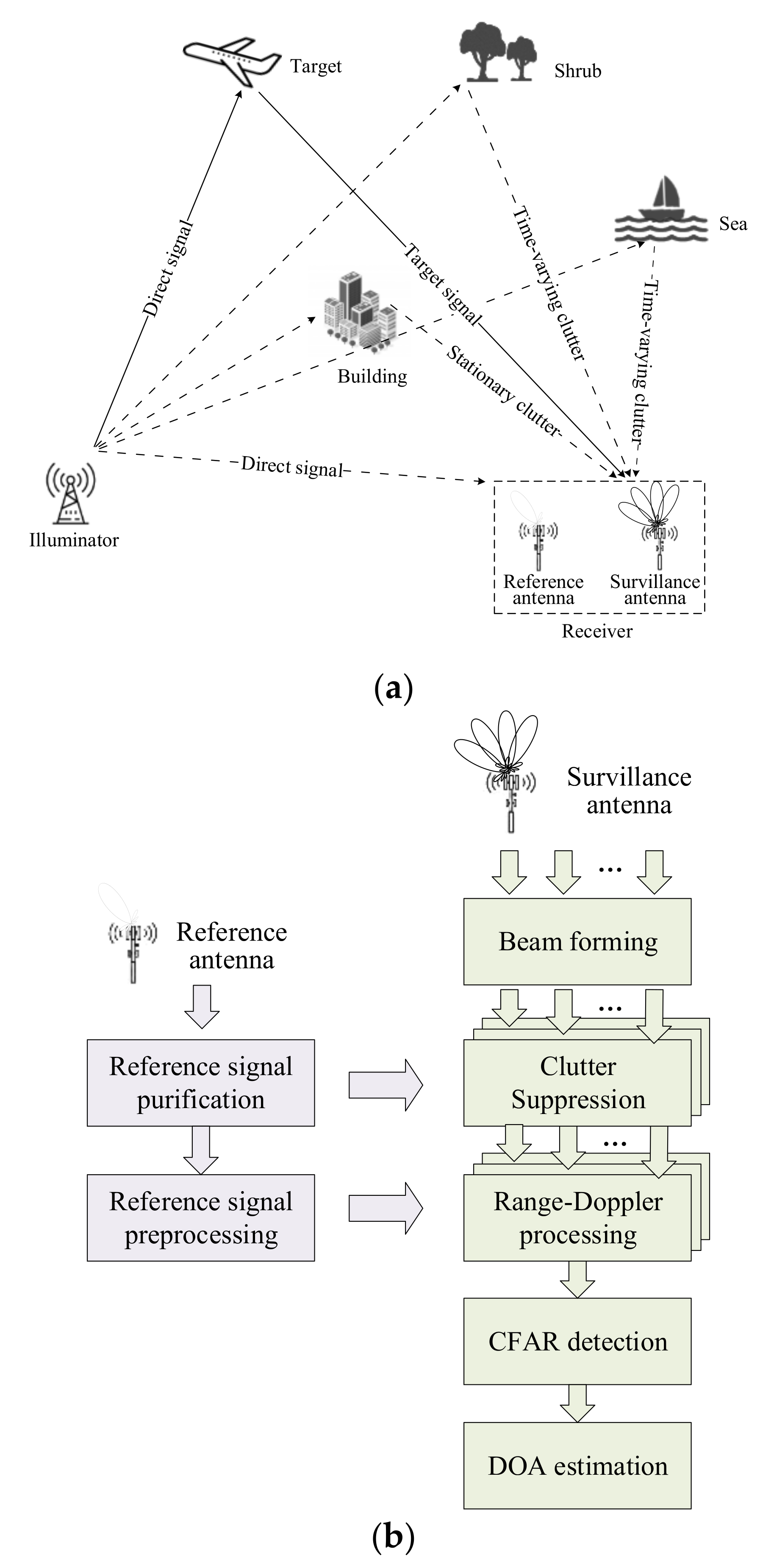
A typical PBR system scenario under the complex clutter environment is constructed in Figure 1a. Additionally, as a new system radar, the typical PBR system signal processing scheme is also given in Figure 1b. We suppose that the transmitter is an omnidirectional antenna in the azimuth angle and the PBR receiver consists of two types of antennas: the dedicated reference antenna steers towards the illuminator and the surveillance antenna pointed in the airspace to be detected.
Assuming that the illuminator transmits a narrow signal w(t) with bandwidth B, after the down-conversion, the complex envelope of reference signal is given as
where ar is the complex altitude and nr(t) is the white Gaussian noise.
For the representation of surveillance signal, different contributions are considered in this paper. Since the commonly used illuminators operate at U/V band, the complex clutter can be regarded as a collection of multiple discrete scatterers, which mainly causes powerful reflections [31]. Hence, the continuously and densely distributed clutter backscattering environment can be emulated by the reflections of a great deal of such scatterers. The surveillance signal contaminated by stationary clutter is first analyzed following the above assumption, and its complex envelope is shown as
where a0 is the complex altitude of the direct path signal by the side/back lobe of the surveillance signal. ai and τci are the complex amplitude and the propagation delay (in respect to direct path signal) of ith stationary scatterer component, respectively. Particularly, the delays τci involve fractional and integer multiple of the sampling period. Nc is the number of scatterer components. bm, τm and ftm are the complex amplitude, delay and Doppler frequency shift of the mth target, respectively. Nt is the target number. ns(t) is the white Gaussian noise term in the surveillance signal.
Considering the time-varying environment, the surveillance signal is also influenced by the slow-moving clutter. Compared with stationary clutter, the time-varying clutter is characterized by the nonzero Doppler spectrum, i.e., clutter scatterers distribute in a specific velocity scope with zero center [16,35]. Thus, the time-varying clutter can be represented by a set of continuous frequency components around the zero-Doppler, as follows
where fcp is the spread Doppler frequency; cpq and τpq are the complex amplitude and delay of the qth time-varying clutter with doppler shift fcp, respectively. Similarly, τpq involves a fractional and integer multiple of the sampling period. Np∙Nq is the number of scatterers.
2.2. PBR Target Detection
In PBR systems, the target detection method, i.e., CAF, is based on the optimal matched filter concept. The Doppler-shifted version of the time-delayed reference signal is used to generate a bank of parallel filters [6,36]. Each filter matched to a target at delay τ and Doppler frequency fd. Therefore, the CAF is also called as range-Doppler processing, and it can be given as
where T is integration time.
Performing a Fourier transform on (4), another form of CAF can be obtained,
where S(f) and R(f) are the corresponding frequency-domain form of s(t) and r(t).
A matched filter receiver can enhance the target detection performance. The target range and velocity information can be evaluated by finding the maximum of the detection function (4) and (5). However, when the complex clutter is present in surveillance signal, the target is completely undetectable owning to the extensive range-Doppler spreading of clutter sidelobes.
3. ECA and ECA-B Analysis
3.1. ECA Analysis
In PBR, the ECA [20,31] is a widely used method for clutter suppression, since the filter coefficients are estimated without an iteration convergence process. The ECA operates by projecting the surveillance to the orthogonal subspace formed by different Doppler-shift versions of the time-delayed reference signal. Each vector in this specific clutter subspace corresponds to a clutter component to be removed. Its principle is described as follows.
In general, the PBR operates with signals sampled with a sampling rate fs. The nth sample is taken at time n/fs, and we can write the samples s(t) as
where N = T⋅fs is the number of samples within the CPI, [⋅]T is the transpose operator.
The samples of reference signal r(t) can be given as
where D-1 is the number of additional samples to ensure the desired integration over an extent of D time-delayed bins.
Subsequently, the projecting subspace is generated as
where Γ is the incidence matrix ensuring that only the last N rows of the following matrix are considered, which is shown as
ΛF is a diagonal matrix which is applied to add the Doppler shift information.
And rref is zero-Doppler projecting subspace written as
where Γ is a permutation matrix to generate a one-sample-delayed reference signal matched to a clutter scatterer, defined as
Therefore, a (2F + 1)K-dimensional clutter subspace is defined based on the columns of X. By resorting to least square (LS) criterion, the filter weight to be estimated is calculated as
where [∙]H is Hermitian transpose operator. Therefore, the surveillance signal without clutter is achieved as
Generally, the ECA is able of accurately estimating the clutter coefficients under the condition of enough CPI. Nevertheless, the construction of a subspace requires correspondence with every possible scatterer. Thus, the subspace dimension is usually extremely large, due to the complexity of the practical propagation environment, i.e., the multipath clutter is distributed over a mass of range cells. The vast computational complexity and memory cost pose a serious challenge to engineering implementations of ECA. Therefore, the ECA is only performed in the case of stationary clutter.
3.2. ECA-B Analysis
In order to improve the PBR’s adaptability to time-varying clutter environment, the ECA-B [26,31] is proposed. Assuming that the signal is divided into LB batches, each batch contains NB = N/LB samples. The suppression result of the lth batch can be given as
where represents the subspace in each batch, which is only consisted of time-delayed rl; is the filter coefficient in each batch. As the filter coefficients are updated in a short duration, the cancellation notch is extended in the frequency domain, which produces two improvements. The first is that the system becomes capable of rejecting time-varying clutter. Then, and secondly, the computational cost is relatively reduced, due to the subspace’s dimensional reduction.
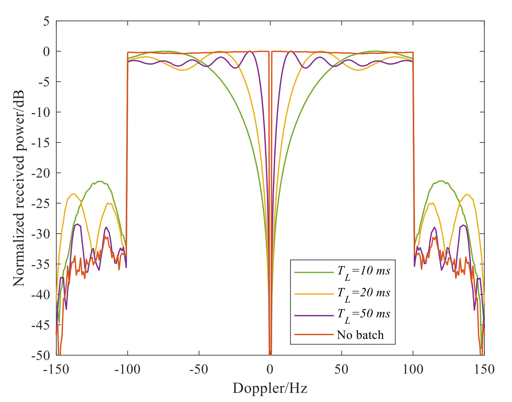
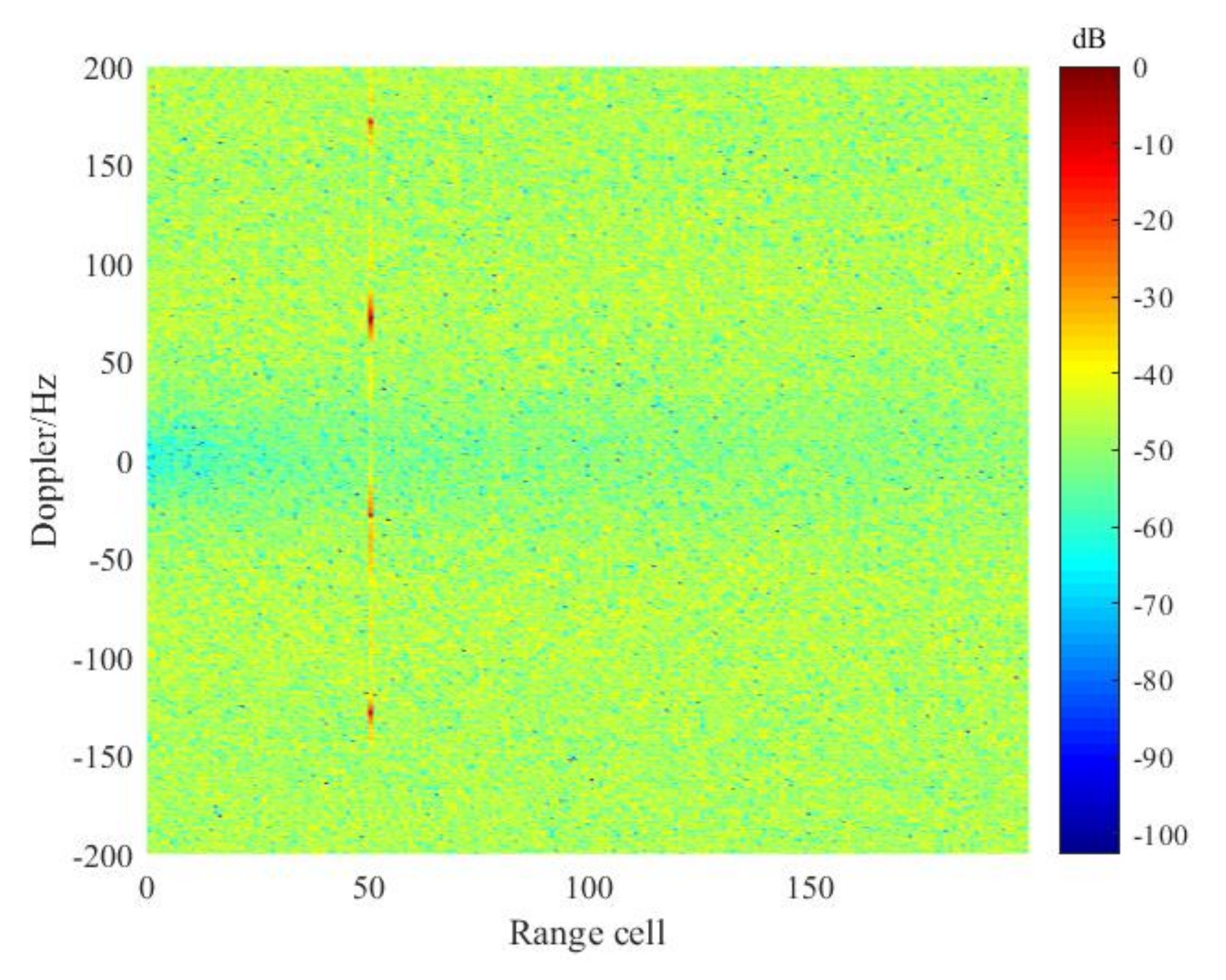
However, the ECA-B method still has the following limitations. Firstly, due to the non-satisfactory cancellation notch feature in the frequency domain, i.e., the transition band falls slowly, the effective width (stop band) of the cancellation notch in the frequency domain is less than 1/TB, where TB is the batch duration. Figure 2 shows the frequency selectivity (the cancellation notch feature in frequency domain) of the ECA-B with different batch durations. In Figure 2, an FM signal is simulated as the direct path signal, at the sampling rate and CPI are fs = 200 kHz and T = 1 s, respectively. It can be shown that, to remove the clutter with a Doppler spectrum bandwidth of 1/TB, the received signal should be divided into smaller batches. However, a smaller batch duration will cause a series of periodic peaks and reduce the target SNR simultaneously; in the case of the slow-moving target, this is close to the transition zone. Figure 3 shows the RD result of a target located in the transition-band in which periodic peaks occur, seriously degrading the detection probability. In Figure 3, the batch duration TB is 10 ms, and the target is located at −28 Hz and in the 50th range bin.
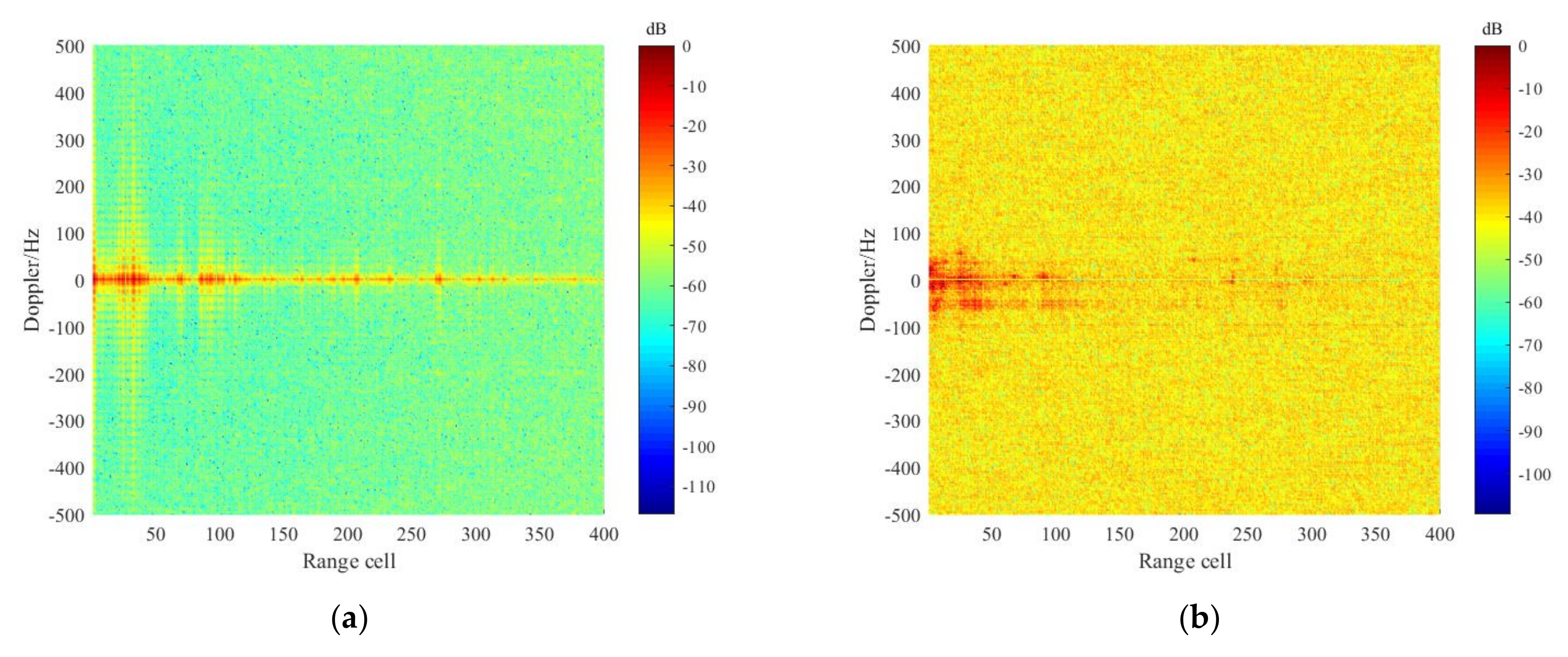
In an actual clutter environment, an interesting feature of the time-varying clutter is that it is spread in the velocity direction for short ranges. For longer ranges, the clutter energy is distributed in the zero-velocity resolution cell [4]. Therefore, when a distant target has the same Doppler characteristics as short-range clutter, the target will be removed. Figure 4 shows the distribution characteristics of the complex clutter, where the data is received via DTMB-based PBR system. Note that the time-varying clutter spectrum is presented after the stationary clutter is suppressed, since the sidelobes of the strong stationary clutter will mask the time-varying clutter.
Additionally, both the ECA and ECA-B methods are temporal filters, as the constructed large-dimensional subspace in the time-domain cannot fully represent all the actual clutter characteristics, such as fractional-order clutter. Hence, the clutter suppression performance is further limited.
4. Complex Clutter Suppression via ECA-FB and ECA-FBD
In order to achieve better clutter cancellation performance with limited computational cost, a novel ECA-FB method and its enhanced version, ECA-FBD are proposed. The detailed process is introduced as follows.
4.1. ECA-FB
From the implementation of ECA-B, we can conclude that the cancellation notch is extended in the frequency domain by dividing the receiving signal into small batches. Therefore, the time-varying clutter can be removed without increasing the subspace dimension. Inspired by ECA-B, we developed a batch version of the ECA in the frequency domain (ECA-FB) to cope with stationary clutter. Specifically, in this method, the received signal is divided into a set of consecutive short fragments (subbands) in the frequency domain, then the ECA is performed to subtract the stationary clutter component from the surveillance signal without the construction of clutter subspace.
Performing a discrete Fourier transform (DFT) on the surveillance and reference signals, the surveillance signal in Doppler frequency domain is represented as
where W[g] is the Doppler spectrum of direct path signal, g = 1, ⋯, N is the normalized Doppler unit corresponding to the Doppler frequency; is the normalized delay unit of ith clutter with delay τci, ; and are the normalized Doppler and delay unit of the mth target with Doppler fdm and delay τm,.
The reference signal in Doppler frequency domain is given as
Assuming that the signal bandwidth is B, the signal S[g] and R[g] are subsequently divided into a set of consecutive short fragments (subbands) with bandwidth BL. Each subband contains NL samples. The lth subband signal is expressed as
where l = 1, 2,⋯, L; g = 1,2,⋯, NL, L is the number of subbands. Note that the direct path signal and stationary clutter are merged in (18), denotes the delay of the direct-path signal.
In PBR field, the range resolution ∆R [37] is related to the signal bandwidth, as follows
where c is the light speed; β is the bistatic angle.
It can be seen from (20) that the division of signal subbands will coarsen the range resolution ∆R. The range resolution in each subband will be further written as
When the number of signal subbands is large enough, so that the coverage of the range resolution ∆RL exceeds the maximum clutter distance, all the stationary clutter will occupy only one degree of freedom (DOF) in each subband. As a consequence, the influence of stationary clutter (including fractional-order clutter) can be regarded as exactly the same for all the frequency component at the same subband, and thus the lth subband surveillance signal can be written as
From (22), it is clear that the spectrum Wl of each subband is independent of its delay to the direct path signal. Accordingly, the contributions of series of clutter for each frequency component g at the same lth subband can be combined to a complex amplitude correlated with Wl. In particular, we pay more attention to the subband surveillance signal; since the Doppler shift is derived from the target movement, the target signal spectrum can be regarded as uncorrelated with Wl. Therefore, applying the ECA to reject stationary clutter in each subband, the corresponding outputs are shown as
where is the subspace to projecting the subband surveillance signal Sl. Since the DOF of clutter is limited to 1, the subspace can be regarded as the subband reference signal Rl, formed by just one vector with the dimension NL × 1, as follows
which means the clutter coefficient to be estimated is a complex constant. Thus, the ECA-FB can achieve an improved rejection of stationary clutter with significantly reduced computational and memory burden, especially for dense stationary clutter distributed over large distances. Finally, all the subband surveillance signals, after stationary clutter suppression, are recombined Ssur = [Ssur-0, Ssur-1, ⋯, Ssur-L-1], and therefore coherent integration is performed to achieve target information via (5).
Supposing that the stationary clutter order is 100 in the surveillance signal, we perform ECA-FB with the different number of subbands to illustrate the performance of the algorithm. The corresponding RD results at the zero Doppler cut are given in Figure 5, from which we can find that the more subbands, the wider the cancellation notch formed by ECA-FB.
4.2. ECA-FBD
Assuming that the PBR operates in a specific environment (shrub, lake, or sea), the clutter may present a narrow but nevertheless nonzero spectral width, which cannot be completely stationary. Therefore, to suppress such time-varying clutter, we further propose a modified ECA-FB method with Doppler extension (ECA-FBD).
Firstly, after stationary clutter suppression, the surveillance signal contaminated by time-varying clutter in the frequency domain can be written as
where and are the normalized Doppler and delay unit of the Doppler fcp and delay τpq; Nt is the combination of noise and residual clutter.
In (25), it is obvious that the time-varying clutter can be regarded as a collection of multiple time-delayed scatterers at a specific Doppler frequency shift, fcp. Meanwhile, from the previous section, we know that the division of subbands can limit the DOF of clutter in the range dimension. Therefore, the time-varying projecting subspace can be formed by adding a continuous Doppler shift to the stationary clutter subspace . Specifically, in ECA-FBD method, the surveillance signal in (25) and reference signal R in (17) are redivided into LD subbands to limit the DOF of the time-varying clutter in the range dimension. The projecting subspace in the lth (l = 1,2,⋯, LD) subband is given as follows
where and are the left and right permutation matrix to generate different Doppler shift features in frequency domain, respectively, defined as
where is the length of subband signal.
Therefore, a 2F-dimensional time-varying clutter subspace is defined based on the columns of . By resorting to LS criterion, the filter coefficients can be estimated and thus mitigate the time-varying clutter.
Noted that in ECA-FBD, the number of Doppler extension F and the number of subbands LD can be set flexibly to adapt different time-varying environments. Usually, LD < L, due to the Doppler-shifted clutter being distributed over short ranges, as shown in Figure 4; otherwise far-distant targets with the same Doppler shift will also be suppressed. Therefore, the ECA-FBD is considered a cascade method of ECA-FB in the presence of a time-varying clutter environment. Additionally, the summarized framework of the proposed method is given in Algorithm 1 while the flowchart is shown in Figure 6.
| Algorithm 1. The main processes of the proposed methods | |
| 1 | Input: Original surveillance signal s(t) and reference signal r(t), subbands number L, LD and Doppler extension number F. |
| 2 | Discrete Fourier transform: Apply DFT on s(t) and r(t) to obtain S(g) and R(g), respectively. |
| 3 | Subband division: Divide the signal S[g] and R[g] into L fragments with bandwidth BL. |
| 4 | Stationary clutter suppression: Go through each l in [1, L] to conduct ECA operation. |
| 5 | For l = 1, ⋯ , L do |
| 6 | Construct the one-dimensional clutter subspace via (24). |
| 7 | Estimate the clutter coefficient . |
| 8 | Subtract the stationary clutter component to obtain the clutter suppressed signal Ssur-l. |
| 9 | end |
| 10 | Subband synthesis: Recombine the subband signal to achieve Ssur. |
| 11 | Subband redivision: Redivide the signal Ssur and R into LD fragments. |
| 12 | Time-varying clutter suppression: Go through each l in [1, LD] to conduct ECA operation. |
| 14 | For l = 1, ⋯ , LD do |
| 15 | Construct the clutter subspace via (26)–(28). |
| 16 | Subtract the time-varying clutter component. |
| 17 | end |
| 18 | Output: Recombine the subband signal after removing time-varying clutter and then output it for coherent integration. |
5. Performance Analysis and Some Remarks
5.1. Computational Complexity
In what follows, the computational complexity of major steps in the proposed methods are analyzed in terms of complex multiplications (Mcs). Specifically, due to the ECA-FB and ECA-FBD being presented for stationary and time-varying clutter suppression, respectively, we analyze the computational cost of these methods in two scenarios. Without a loss of generality, fractional-order clutter is not considered in this section.
(1) Stationary clutter scenario: Assuming that the clutter order is K, the computational complexity of ECA-FB and ECA are analyzed as follows. Specifically, in ECA-FB, the received signal is first converted from the temporal domain to the frequency domain by performing FFT, which requires Nlog2(N) Mcs. Then, the signal in the frequency domain is divided into L subbands with the length of NL. In each subband, ECA is performed, i.e., is repeated in each subband. For simplicity, we assume that and . Note that both the calculation of xl and yl include NL Mcs, since the matrix is a NL × 1 vector, and therefore 1 Mc is needed for achieving the filter coefficient, αl = xl∙yl. After that, the estimation of stationary clutter requires NL Mcs. Last, the clutter is removed via subtracting from Sl. The overall computational cost of ECA-FB is Nlog2(N) + (3NL + 1)L Mcs. As for ECA method, which has been appropriately optimized in [26], and 3N(1 + log2(N)) + K2(1 + log2(K)) Mcs are required. Due to the subspace dimension of ECA-FB being unrelated to the clutter order, its computational load is significantly reduced compared with ECA, especially for large clutter orders and long CPIs. Additionally, it is worth noting that the ECA-FB is more suitable in parallel processing since the matrix multiplications in each subband are much smaller and independent of each other.
(2) Time-varying clutter scenario: Assuming that the time-varying clutter is extended with a narrow Doppler spectrum, the number of Doppler extension bins is set as 2F, the computational complexity of ECA-FBD and ECA-B are analyzed as follows. In ECA-FBD, the received signal in frequency domain is redivided into LD subbands with the length of ND, and the time-varying projection matrix is generated with dimension ND × 2F. Therefore, the computational complexities of ECA-FBD are LD[3ND(1 + log2(ND))+ F2((1 + log2(F)))] Mcs. Besides, the ECA-B needs LB[3 NB(1 + log2(NB)) + K2((1 + log2(K)))] Mcs, in which the received signal is divided into LB batches, where the length of each batch is NB. In ECA-B, the projecting subspace dimension is related to the stationary clutter order K, which is usually much larger than 2F. Therefore, the computational complexity of ECA-FBD is lower than that of ECA-B.
The detailed computational complexities of above-mentioned methods are concluded in Table 1. Assuming that the signal sampling rate is fs = 200 kHz and the other relevant parameters of the clutter suppression are given as: K = 300, F = 20, L = 1000, LD = 100, LB = 40. The relationship between computational complexity and CPI for different suppression methods are shown in Figure 7. Note that the ECA-FBD is a cascade method of ECA-FB in the presence of time-varying clutter. On the contrary, the ECA-B can reject the stationary and time-varying clutter simultaneously. Therefore, in the time-varying clutter scenario, the sum of the computational complexity of the ECA-FB and ECA-FBD is used to compare with ECA-B method. It can be seen that the proposed methods have a relatively lower computational cost than that of the ECA and ECA-B, respectively.
5.2. Some Remarks
Remark 1.
Compared with ECA, the proposed ECA-FB method can obtain comparable suppression performance with significantly reduced computational burden and memory cost since there is no need to construct the multi-dimensional clutter subspace. Especially, the ECA-FB is effective for the wideband PBR systems (DTMB, LTE). In the same stationary clutter environment, the clutter order of wideband PBR is larger than for narrow PBR (FM), due to the finer range resolution.
Remark 2.
Compared with ECA-B, the ECA-FBD is considered as a cascading method of ECA-FB in the presence of time-varying clutter. It can not only effectively suppress the time-varying clutter but also obtain superior detection performance in the presence of slow-moving targets. Specifically, ECA-FBD would not weaken the slow-moving target SNR and induce periodical peaks. Additionally, when a distant target has the same Doppler characteristics as the short-range clutter, the target will not be removed, which is described in Section 7.2 in detail.
Remark 3.
In practice, the delay of stationary and time-varying clutter may not be an integer multiple of the sampling period, which is located at delays in between sample points, distributed across delay bins. The popular ECA and ECA-B are temporal filters, which have a significant limitation in the presence of fractional-order clutter. The proposed methods can limit all clutter types DOF to one via the dividing of subbands, and thus enhance the adaptability of PBR in fractional-order clutter environments. Therefore, the proposed methods are more effective and robust to complex clutter environments.
6. Simulation Results
To evaluate the efficiency of the proposed clutter suppression methods, two simulated scenarios, the stationary and time-varying clutter scenarios, are presented in this section. Additionally, in order to compare the experiments for complex clutter suppression, ECA and ECA-B are performed as well. Supposing that the DTMB signal is used as the waveform of opportunity, and the parameters of DTMB-based PBR system are listed in Table 2. The simulated parameters of targets and clutter are listed in Table 3. Note that two target types are considered, one slowly moving target and another relatively fast-moving target. Based on this, the SNR gain of the PBR system is about 10lg(BT) = 62 dB, and thus the targets signal SNR after integration are 27 dB, 32 dB, respectively, which is used to evaluate suppression performance in different clutter scenarios.
6.1. Stationary Clutter Scenario
In this scenario, the stationary clutter with integer and fractional order in Table 3 are considered to evaluate the clutter-suppression capabilities. Firstly, the integer order clutter is synthesized in the surveillance signal, which is emulated by 51 continuous and dense scatterers. The detailed parameters are listed in Table 3. In addition, the fast-moving target A at (90, 100 Hz) with SNR of −35 dB is added in the surveillance signal.
To remove the masking effect of clutter in the target detection, the ECA-FB and ECA are performed, respectively. Note that the number of the subbands, L, is set as 1000 to sufficiently widen the cancellation notch, so the DOF of clutter is limited to one. The ECA suppression order is set as 51. The corresponding integration results are given in Figure 8. As is apparent, both the proposed ECA-FB and ECA can effectively remove the integer-order clutter components, and target A obtained the desired SNR gain, even though the ECA-FB required little computational cost.
Then, fractional-order clutter is added to the surveillance signal, the RD results after clutter rejection via ECA-FB and ECA are given in Figure 9a,b, respectively. It can be seen from Figure 9a that the proposed method can also acquire well suppression performance in the presence of such clutter scenario, and the targets can be clearly observed. Whereas, in Figure 9b, target A is substantially masked by the sidelobes of residual fractional-order clutter, indicating that the ECA is poor in the case of clutter with fractional delays.
6.2. Time-Varying Clutter Scenario
In the following scenario, we access the suppression performance of time-varying clutter via the proposed ECA-FBD. Specifically, a set of slowly moving scatterers with narrow Doppler spectrum is used to emulate the time-varying clutter in the surveillance signal. The maximum range bin is set as 10, since such clutter is distributed over area near the practical clutter environment and the scope of the time-varying Doppler varies from −5 to 5 Hz, with a step size of 1 Hz (detailed parameters are listed in Table 3). The target B is added to the surveillance signal to investigate the suppression performance of proposed ECA-FBD method in the presence of slowly moving target. Additionally, complex white Gaussian noise at 10 dB is further added to the surveillance channel to verify the clutter suppression and target detection performance.
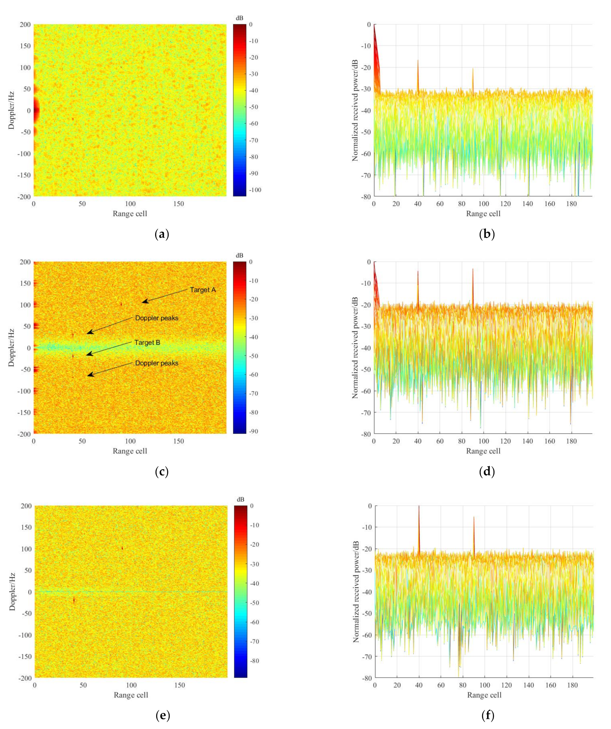
In this simulation, ECA-B was performed for comparison. Without loss of generality, we suppose that the stationary clutter with fractional delays in Section 6.1 have been removed. The RD results, without time-varying clutter cancellation, are given in Figure 10a,b, in which the target energy is significantly submerged in the noise floor. Figure 10c,d gives the RD results after clutter suppression via ECA-B, where the batch duration was 20 ms. As is apparent, the time-varying clutter can be suppressed and the targets A and B are observed clearly in Figure 10c,d. Whereas a series of periodic Doppler peaks occur around the slow-moving target B and the target, SNR is obviously reduced. Note that the period of these peaks is 50 Hz, which corresponds to the batch duration. Additionally, the batch operation in ECA-B also periodically modulated the time-varying clutter, causing that clutter to be distributed with a step of 50 Hz, as given in Figure 10c.
Subsequently, the proposed ECA-FBD was implemented for time-varying clutter removal, and the corresponding RD results are depicted in Figure 10e,f. The number of the subbands LD was set as 50. As is apparent, the time-varying clutter was rejected completely, and target A formed a unique peak without ambiguous Doppler peaks. Additionally, it can be seen from Figure 10f that the SNR of targets A and B are consistent with the desired system energy gain. In conclusion, considering the time-varying clutter environment, the proposed ECA-FBD can obtain not only better suppression performance, but also superior detection performance in the presence of slow-moving targets, as compared with ECA-B.
7. Experimental Results
In this section, the improvement of the proposed methods, ECA-FB and ECA-FBD are evaluated using multiple sets of measured data acquired from the experimental PBR system. The evaluation allows us to further observe the adaptability of the proposed methods in actual clutter environment.
7.1. Experimental Results for the DTMB-Based PBR
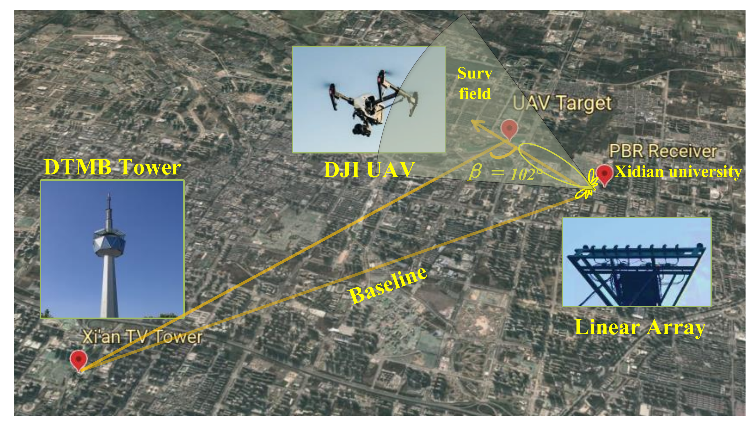
The practical feasibility of the presented method is validated in this section using field experimental data gathered from a DTMB-based PBR system developed by Xidian University in China [13]. Figure 11 shows the geometry of the UAV detection experiment trial. The bistatic angle was β = 102°. The experiment was performed on 20 December 2019, near an open space at Xidian University. Xi’an television tower was exploited as the illuminator. The surveillance antenna was a uniform linear array with eight elements. The CPI was 0.2 s, and the remaining system parameters are consistent with Table 2. Finally, the detecting target was a cooperative UAV (DJI INSPIRE 1) flown with a velocity 10 m/s and at an altitude of approximately 100 m. The purpose of this experiment was to verify the clutter suppression performance of the proposed ECA-FB in the presence of fractional-order stationary clutter. In this specific environment, the fractional-order clutter was also continuously and densely distributed, which was predicted to seriously affect the system’s detection ability.
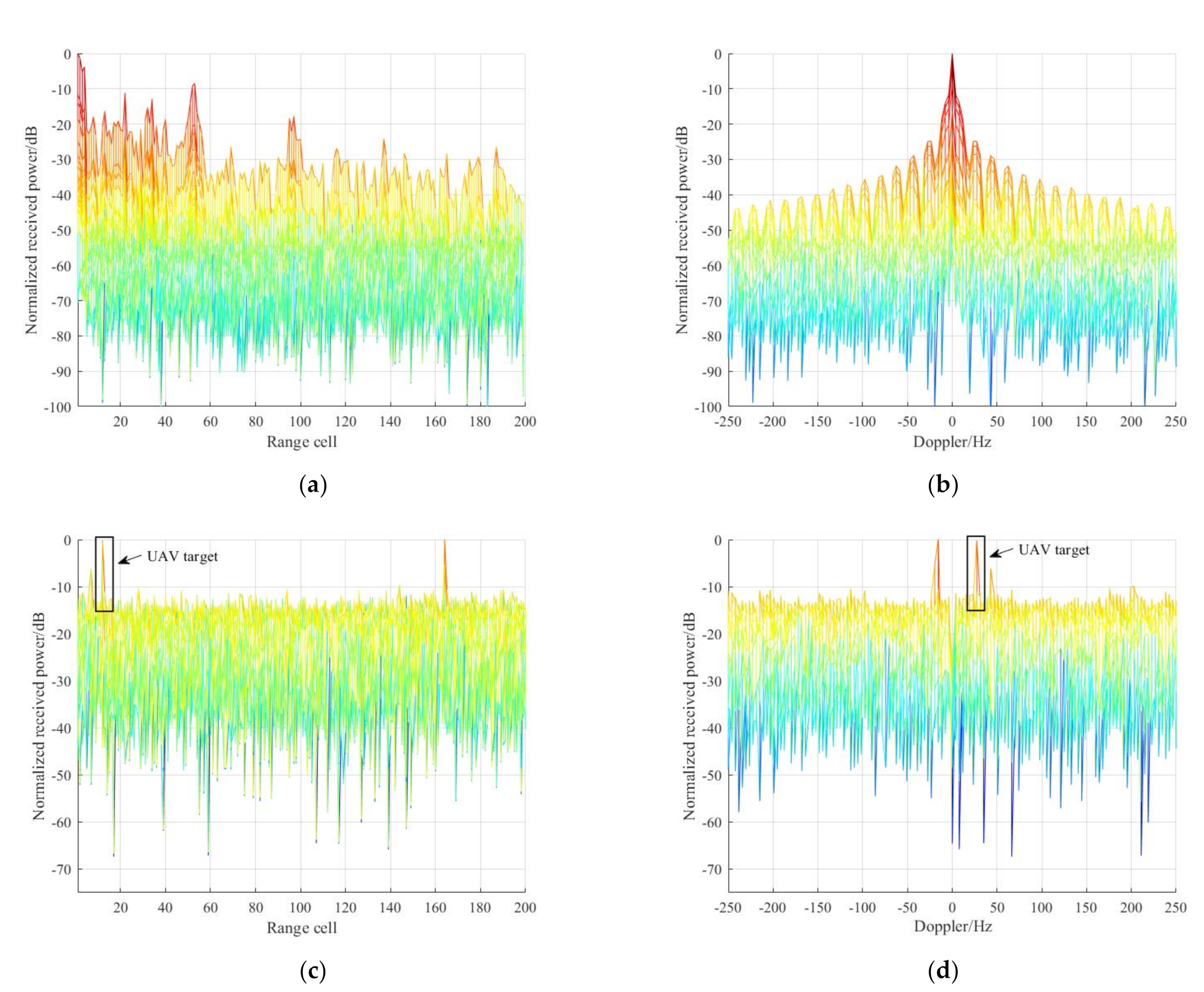
Firstly, the RD results between the reference signal and raw surveillance signal are given in Figure 12a,b. It can be seen that the target is completely masked due to the mainsides and sidelobes of the strong direct path signal and clutter. Subsequently, the conventional ECA was performed to suppress the undesired clutter components. Note that the maximum suppressed range bin (clutter order) was set to be 1000, since the range resolution of DTMB signal is fine, about 40 m. The RD results, after ECA cancellation, are given in Figure 12c,d, from which we find that several targets have been successfully detected; the UAV target is marked by a black box, which is located at range bin 12, at Doppler 27.3 Hz.
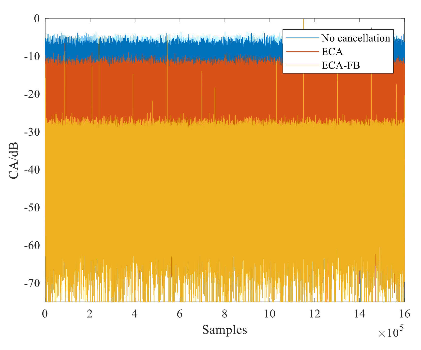
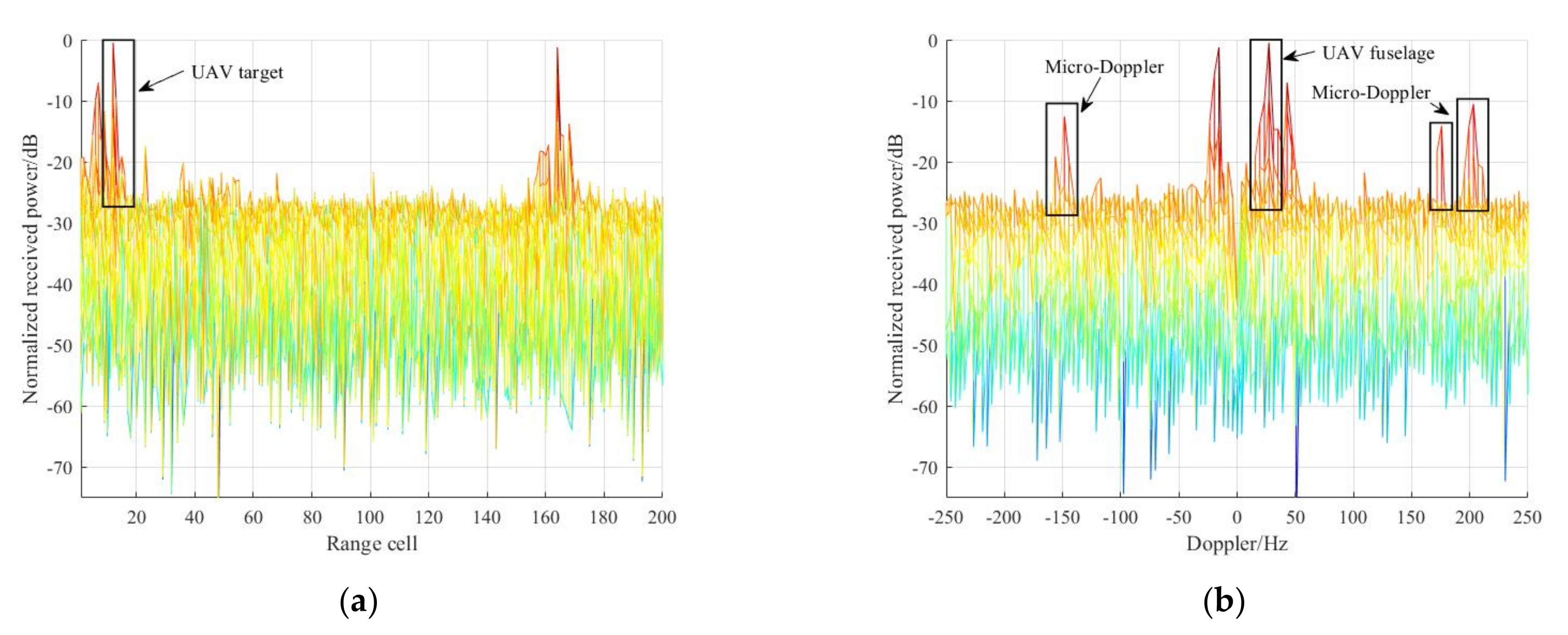
After that, the proposed ECA-FB method was applied for clutter removal. Note that the number of the subbands in the ECA-FB was set at 10,000 for achieving a wider cancellation notch, as analyzed in Section 4.1. Firstly, the clutter attenuation (CA), defined as the ratio between the power levels of the surveillance signal before and after clutter suppression, of the ECA and ECA-FB are shown in Figure 13. It is noted that, compared with ECA, the CA of ECA-FB was significantly enhanced, about 15 dB, which means the clutter components were further reduced. Then, the RD processing was performed and the integration results are shown in Figure 14. It is worth noting that the UAV target is not only effectively detected, but its SNR is also greatly improved compared with Figure 12c,d, by almost 13 dB. Significantly, since the UAV target SNR was improved, the micro-Doppler effect of the rotor wing in the UAV can be observed clearly in Figure 14b, symmetrically distributed around the UAV fuselage [38]. This is an advantage for the classification and recognition of UAVs of slow velocity and small sizes in low-altitude areas.
7.2. Experimental Results for the FM-Based PBR
Further, the effectiveness of the proposed methods was verified using the experimental data collected from an FM-based PBR. The experiment was performed near an open space at Xi’an Xianyang international Airport. The aim of this experiment was to investigate the adaptability of the proposed method against complex detection scenarios, i.e., time-varying clutter, substantial multipath clutter and slow-moving targets. The system operated at the sampling rate of 200 kHz, and its CPI was 1 s.
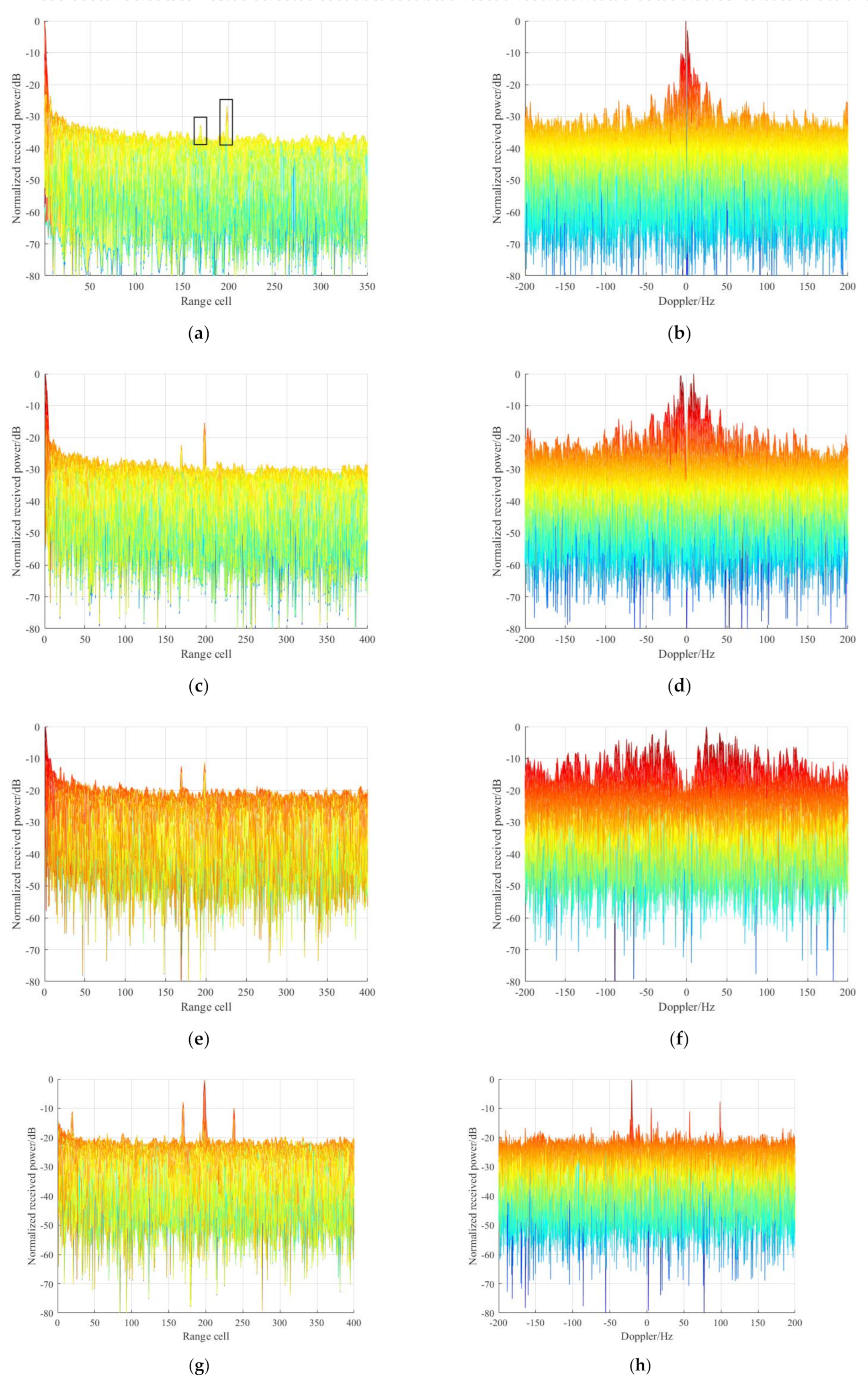
In order to carry out comparison experiments for complex clutter suppression, ECA and ECA-B with different batches were explored as well. The corresponding RD results after clutter suppression via different methods are given in Figure 15. Firstly, the RD results after clutter cancellation by ECA are shown in Figure 15a,b, in which we note that two targets are detected at (169, 98.6 Hz), (198, −20.5 Hz). Additionally, residual clutter occurs following the ECA clutter suppression because of the time-varying clutter environment, which presents a spread Doppler spectrum and thus degrades detection ability.
Then, the RD results via ECA-B with different batches are given in Figure 15c–f. Specifically, Figure 15c,d depicts the RD results of the ECA-B method with a batch duration of 100 ms. As is apparent, the time-varying clutter is suppressed via the spread of the cancellation notch in the frequency domain, and the targets’ SNR is improved. After that, the ECA-B method with batch duration 20 ms was performed for time-varying cancellation. The RD results are given in Figure 15e,f. It can be observed that the slow-moving target at (198, −20.5 Hz) suffers from undesirable SNR loss in spite of the better time-varying clutter suppression performance compared with Figure 15c,d. The reason for this is that the wider cancellation notch may have weakened the detectability of the slow-moving target, which is a limitation of ECA-B.
Finally, the ECA-FB and ECA-FBD were cascaded, to cope with such a cluttered environment. The number of subbands, LD, in ECA-FBD was set as 20 for covering short-range time-varying clutter. The corresponding results are given in Figure 15g,h, from which we see that the time-varying clutter is effectively reduced, and the SNR of targets at (169, 98.6 Hz) and (198, −20.5 Hz) are greatly improved. Moreover, two additional targets are clearly observed at (20, 57.6 Hz) and (238, 5.8 Hz), which means that the proposed methods were more effective, compared with ECA-B, in terms of detecting slow-moving targets.
In conclusion, the measured results further verify the effectiveness of the proposed methods, which are consistent with the simulation model constructed in Section 6, completely, such as Figure 9 corresponds to Figure 11 and Figure 13. Therefore, the proposed ECA-FB and ECA-FBD have better adaptability to complex environments, and their survivability will be greatly improved.
8. Conclusions
In this paper, we have introduced and analyzed the characteristics of complex clutter in PBR system. In the presence of complex clutter, the detection performance of a PBR system will be greatly reduced since the effect of clutter sidelobes spread throughout the entire RD plane. A novel method, named ECA-FB, was firstly proposed in the frequency domain for stationary clutter suppression. Specifically, the basis of this method is that the division of subbands can limit the DOF of stationary clutter (involving fractional-order clutter) and thus the Doppler spectrum of each subband is independent of its delay to the direct path signal. Further, considering time-varying clutter environments, we have also presented a modified method, i.e., the ECA-FBD, conducted by extending the Doppler shifts to the ECA-FB. Note that the ECA-FBD method was not performed separately, but in a cascade with ECA-FB in this paper. Compared with ECA-B, the ECA-FBD avoided the loss of target SNR and the appearance of periodic peaks in the case of slow-moving target detection. Additionally, the proposed ECA-FB and ECA-FBD methods could not only obtain better suppression performance in the presence of fractional-order clutter, but also required lower computation loads compared with temporal methods. Both simulation and experimental data confirmed the effectiveness of the proposed methods, providing a valuable basis for their practical application in PBR systems. Although we have focused on the use of practical FM and DTMB signals in this paper, it should be noted that the proposed methods can also be applied to the PBRs of other signal types.
Author Contributions
The work described in this article is the collaborative development of all authors. L.Z. and J.W. contributed to the idea of result processing and designed the algorithm. L.Z. and J.S. made contributions to data measurement and analysis. L.Z. participated in the writing of the paper. N.L. revised the writing of the paper. All authors have read and agreed to the published version of the manuscript.
Funding
This research was funded by “China Electronics Technology Corporation”, grant number 201812130066 and the APC was funded by “China Electronics Technology Corporation”.
Data Availability Statement
Due to the nature of this research, participants of this study did not agree for their data to be shared publicly, so supporting data is not available.
Acknowledgments
The authors would like to thank the support of the laboratory and university.
Conflicts of Interest
The authors declare no conflict of interest.
References
- Patel, J.S.; Fioranelli, F.; Anderson, D. Review of radar classification and RCS characterisation techniques for small UAVs ordrones. IET Radar Sonar Navig. 2018, 12, 911–919. [Google Scholar] [CrossRef]
- Miao, Y.; Li, J.; Bao, Y.; Liu, F.; Hu, C. Efficient Multipath Clutter Cancellation for UAV Monitoring Using DAB Satellite-Based PBR. Remote Sens. 2021, 13, 3429. [Google Scholar] [CrossRef]
- Griffithsm, H.; Baker, C.J. An Introduction to Passive Radar; Artech House: Norwood, MA, USA, 2017. [Google Scholar]
- Malanowski, M. Signal Processing for Passive Bistatic Radar; Artech House: Norwood, MA, USA, 2019. [Google Scholar]
- Colone, F. DVB-T-Based Passive Forward Scatter Radar: Inherent Limitations and Enabling Solutions. IEEE Trans. Aerosp. Electron. Syst. 2021, 57, 1084–1104. [Google Scholar] [CrossRef]
- Palmer, J.E.; Harms, H.A.; Searle, S.J.; Davis, L. DVB-T Passive Radar Signal Processing. IEEE Trans. Signal Process. 2013, 61, 2116–2126. [Google Scholar] [CrossRef]
- Blasone, G.P.; Colone, F.; Lombardo, P.; Wojaczek, P. Passive Radar DPCA Schemes with Adaptive Channel Calibration. IEEE Trans. Aerosp. Electron. Syst. 2020, 56, 4014–4034. [Google Scholar] [CrossRef]
- Fu, Y.; Wan, X.; Zhang, X. Side Peak Interference Mitigation in FM-Based Passive Radar Via Detection Identification. IEEE Trans. Aerosp. Electron. Syst. 2017, 53, 778–788. [Google Scholar] [CrossRef]
- Malanowski, M.; Kulpa, K.; Kulpa, J. Analysis of detection range of FM-based passive radar. IET Radar Sonar Navig. 2014, 8, 153–159. [Google Scholar] [CrossRef]
- Daun, M.; Nickel, U.; Koch, W. Tracking in multistatic passive radar systems using DAB/DVB-T illumination. Signal Process. 2012, 92, 1365–1386. [Google Scholar] [CrossRef]
- Choi, S.; Crouse, D.; Willett, P.; Zhou, S. Multistatic target tracking for passive radar in a DAB/DVB network: Initiation. IEEE Trans. Aerosp. Electron. Syst. 2015, 51, 2460–2469. [Google Scholar] [CrossRef]
- Lü, M.; Yi, J.; Wan, X.; Zhan, W. Cochannel Interference in DTMB-Based Passive Radar. IEEE Trans. Aerosp. Electron. Syst. 2019, 55, 2138–2149. [Google Scholar] [CrossRef]
- Zuo, L.; Wang, J.; Zhao, T.; Cheng, Z. A Joint Low-Rank and Sparse Method for Reference Signal Purification in DTMB-Based Passive Bistatic Radar. Sensors 2021, 21, 3607. [Google Scholar] [CrossRef] [PubMed]
- Geng, Z.; Xu, R.; Deng, H. LTE-based multistatic passive radar system for UAV detection. IET Radar Sonar Navig. 2020, 14, 1088–1097. [Google Scholar] [CrossRef]
- Abdullah, R.S.A.R.; Salah, A.A.; Aziz, N.A.; Rasid, N.A. Vehicle recognition analysis in LTE based forward scattering radar. In Proceedings of the 2016 IEEE Radar Conference (RadarConf), Philadelphia, PA, USA, 2–6 May 2016; pp. 1–5. [Google Scholar]
- Liu, Y.; Yi, J.; Wan, X.; Zhang, X.; Ke, H. Time-Varying Clutter Suppression in CP-OFDM Based Passive Radar for Slowly Moving Targets Detection. IEEE Sens. J. 2020, 20, 9079–9090. [Google Scholar] [CrossRef]
- Schüpbach, C.; Patry, C.; Maasdorp, F.; Böniger, U. Micro-UAV detection using DAB-based passive radar. In Proceedings of the 2017 IEEE Radar Conference (RadarConf), Seattle, WA, USA, 8–12 May 2017; pp. 1037–1040. [Google Scholar]
- Berger, C.R.; Demissie, B.; Heckenbach, J.; Willett, P. Signal Processing for Passive Radar Using OFDM Waveforms. IEEE J. Sel. Top. Signal Process. 2010, 4, 226–238. [Google Scholar] [CrossRef]
- Fang, L.; Wan, X.; Fang, G.; Cheng, F. Passive detection using orthogonal frequency division multiplex signals of opportunity without multipath clutter cancellation. IET Radar Sonar Navig. 2016, 10, 516–524. [Google Scholar] [CrossRef]
- Colone, F.; Cardinali, R.; Lombardo, P. Cancellation of clutter and multipath in passive radar using a sequential approach. In Proceedings of the 2006 IEEE Conference on Radar (RadarConf), Verona, NY, USA, 24–27 April 2006; pp. 1–7. [Google Scholar]
- Malanowski, M. Comparison of Adaptive Methods for Clutter Removal in PCL Radar. In Proceedings of the 2006 International Radar Symposium (RadarConf), Krakow, Poland, 24–26 May 2006; pp. 1–4. [Google Scholar]
- Dawidowicz, B.; Samczynski, P.; Malanowski, M.; Misiurewicz, J. Detection of moving targets with multichannel airborne passive radar. IEEE Aerosp. Electron. Syst. Mag. 2012, 27, 42–49. [Google Scholar] [CrossRef]
- Demissie, B. Clutter cancellation in passive radar using GSM broadcast channels. IET Radar Sonar Navig. 2014, 8, 787–796. [Google Scholar] [CrossRef]
- Blasone, G.P.; Colone, F.; Lombardo, P.; Wojaczek, P. A two-stage approach for direct signal and clutter cancellation in passive radar on moving platforms. In Proceedings of the 2019 IEEE Radar Conference (RadarConf), Boston, MA, USA, 22–26 April 2019; pp. 1–6. [Google Scholar]
- Searle, S.; Gustainis, D.; Hennessy, B.; Young, R. Cancelling strong Doppler shifted returns in OFDM based passive radar. In Proceedings of the 2018 IEEE Radar Conference (RadarConf), Oklahoma City, OK, USA, 23–27 April 2018; p. 0359-0354. [Google Scholar]
- Colone, F.; Palmarini, C.; Martelli, T.; Tilli, E. Sliding extensive cancellation algorithm for disturbance removal in passive radar. IEEE Trans. Aerosp. Electron. Syst. 2016, 52, 1309–1326. [Google Scholar] [CrossRef]
- Searle, S.; Gustainis, D.; Hennessy, B.; Young, R. Aspects of Delay-Doppler Filtering in OFDM Passive Radar. In Proceedings of the 2018 International Conference on Radar (RADAR), Brisbane, QLD, Australia, 27–31 August 2018; pp. 1–6. [Google Scholar]
- Chen, G.; Wang, J.; Zuo, L.; Zhao, D. Two-stage clutter and interference cancellation method in passive bistatic radar. IET Signal Process. 2020, 14, 342–351. [Google Scholar]
- Chabriel, G.; Barrère, J. Adaptive Target Detection Techniques for OFDM-Based Passive Radar Exploiting Spatial Diversity. IEEE Trans. Signal Process. 2017, 65, 5873–5884. [Google Scholar] [CrossRef] [Green Version]
- Tartakovsky, A.G.; Brown, J. Adaptive spatial-temporal filtering methods for clutter removal and target tracking. IEEE Trans. Aerosp. Electron. Syst. 2008, 44, 1522–1537. [Google Scholar] [CrossRef]
- Colone, F.; O’Hagan, D.W.; Lombardo, P.; Baker, C.J. A Multistage Processing Algorithm for Disturbance Removal and Target Detection in Passive Bistatic Radar. IEEE Trans. Aerosp. Electron. Syst. 2009, 45, 698–722. [Google Scholar] [CrossRef]
- Yi, J.; Wan, X.; Li, D.; Leung, H. Robust Clutter Rejection in Passive Radar via Generalized Subband Cancellation. IEEE Trans. Aerosp. Electron. Syst. 2018, 54, 1931–1946. [Google Scholar] [CrossRef]
- Zhao, Z.; Wan, X.; Shao, Q.; Gong, Z.; Cheng, F. Multipath clutter rejection for digital radio mondiale-based HF passive bistatic radar with OFDM waveform. IET Radar Sonar Navig. 2012, 6, 867–872. [Google Scholar] [CrossRef]
- Schwark, C.; Cristallini, D. Advanced multipath clutter cancellation in OFDM-based passive radar systems. In Proceedings of the 2016 IEEE Radar Conference, Seattle, WA, USA, 2–6 May 2016; pp. 1–4. [Google Scholar]
- Liu, S.; Cao, Y.; Yeo, T.S.; Wu, W. Adaptive Clutter Suppression in Randomized Stepped-Frequency Radar. IEEE Trans. Aerosp. Electron. Syst. 2021, 57, 1317–1333. [Google Scholar] [CrossRef]
- Garry, J.L.; Baker, C.J.; Smith, G.E. Evaluation of Direct Signal Suppression for Passive Radar. IEEE Trans. Geosci. Remote. Sensing 2017, 55, 3786–3799. [Google Scholar] [CrossRef]
- Filip-Dhaubhadel, A.; Shutin, D. Long Coherent Integration in Passive Radar Systems Using Super-Resolution Sparse Bayesian Learning. IEEE Trans. Aerosp. Electron. Syst. 2021, 57, 554–572. [Google Scholar] [CrossRef]
- Garry, J.L.; Smith, G.E. Experimental Observations of Micro-Doppler Signatures With Passive Radar. IEEE Trans. Aerosp. Electron. Syst. 2019, 55, 1045–1052. [Google Scholar] [CrossRef]
Figure 1.
PBR system model: (a) observation scenario; (b) signal processing scheme.

Figure 2.
The frequency selectivity of ECA-B with different batch duration.

Figure 3.
RD result after ECA-B clutter suppression with a batch duration TL = 10 ms.

Figure 4.
Complex clutter (stationary time-varying clutter) spectrum of measured DTMB data: (a) stationary clutter; (b) time-varying clutter.
Figure 4.
Complex clutter (stationary time-varying clutter) spectrum of measured DTMB data: (a) stationary clutter; (b) time-varying clutter.

Figure 5.
Zero Doppler cut of RD result after clutter cancellation via ECA-FB with different subband numbers.
Figure 5.
Zero Doppler cut of RD result after clutter cancellation via ECA-FB with different subband numbers.

Figure 6.
Flow chart of the proposed methods.

Figure 7.
The relationship between the computational complexity and CPI of different methods in stationary and time-varying clutter scenarios: (a) stationary clutter scenario; (b) time-varying clutter scenario.
Figure 7.
The relationship between the computational complexity and CPI of different methods in stationary and time-varying clutter scenarios: (a) stationary clutter scenario; (b) time-varying clutter scenario.

Figure 8.
RD results after integer-order clutter cancellation via ECA-FB and ECA: (a) ECA-FB; (b) ECA.
Figure 8.
RD results after integer-order clutter cancellation via ECA-FB and ECA: (a) ECA-FB; (b) ECA.

Figure 9.
RD results after fractional-order clutter cancellation via ECA-FB and ECA: (a) ECA-FB; (b) ECA.
Figure 9.
RD results after fractional-order clutter cancellation via ECA-FB and ECA: (a) ECA-FB; (b) ECA.

Figure 10.
RD results before and after clutter cancellation via ECA-B and ECA-FBD: result before clutter cancellation in top view: (a) and Doppler dimension (b); result of ECA-B in top view (c) and Doppler dimension (d); result of ECA-FBD in top view (e) and Doppler dimension (f).
Figure 10.
RD results before and after clutter cancellation via ECA-B and ECA-FBD: result before clutter cancellation in top view: (a) and Doppler dimension (b); result of ECA-B in top view (c) and Doppler dimension (d); result of ECA-FBD in top view (e) and Doppler dimension (f).

Figure 11.
Scenario of UAV detection experiment trial.

Figure 12.
RD results before and after ECA cancellation: result before clutter cancellation in range dimension (a) and Doppler dimension (b); result of ECA cancellation in range dimension (c) and Doppler dimension (d).
Figure 12.
RD results before and after ECA cancellation: result before clutter cancellation in range dimension (a) and Doppler dimension (b); result of ECA cancellation in range dimension (c) and Doppler dimension (d).

Figure 13.
CA comparison between the ECA and ECA-FB.

Figure 14.
RD results after clutter cancellation via ECA-FB: (a) range dimension; (b) Doppler dimension.
Figure 14.
RD results after clutter cancellation via ECA-FB: (a) range dimension; (b) Doppler dimension.

Figure 15.
RD results after clutter suppression by different methods: result of ECA in the range dimension (a) and the Doppler dimension (b); result of ECA-B with batches duration 100 ms in the range dimension (c) and the Doppler dimension (d); result of ECA-B with batches duration 20 ms in the range dimension (e) and the Doppler dimension (f); results of ECA-FB&ECA_FBD in the range dimension (g) and the Doppler dimension (h).


Table 1.
Computational complexities of different suppression methods.
| Methods | Number of Mcs |
|---|---|
| ECA-FB | Nlog2(N) + (3NL + 1)L |
| ECA-FBD | LD[3ND(1 + log2(ND)) + F2((1 + log2(F)))] |
| ECA | 3N(1 + log2(N)) + K2(1 + log2(K)) |
| ECA-B | LB[3NB(1 + log2(NB)) + K2((1 + log2(K)))] |
Table 2.
Parameters of DTMB-based PBR system.
| Description | Parameter | Value |
|---|---|---|
| total subcarriers | - | 3780 |
| carrier frequency | fc | 666 MHz |
| sample frequency | fs | 8 MHz |
| carrier spacing | ∆f | 2 kHz |
| bandwidth | B | 7.56 MHz |
| frame header mode | - | 1 |
| CPI | T | 0.5 s |
Table 3.
Simulation parameters of clutter and targets.
| Motion Parameters | Target A | Target B | Stationary Clutter | Time-Varying Clutter | |
|---|---|---|---|---|---|
| Integer Order | Fractional Order | ||||
| range bins | 90 | 40 | 0:1:50 | 0.5:1:10.5 | 0:1:10 |
| Doppler (Hz) | 100 | −20 | 0 | 0 | −10:2:10 |
| CNR/SNR (dB) | −39 | −34 | 40:−1:−10 | 25:−2:5 | 10:−1:0 |
Publisher’s Note: MDPI stays neutral with regard to jurisdictional claims in published maps and institutional affiliations. |
© 2021 by the authors. Licensee MDPI, Basel, Switzerland. This article is an open access article distributed under the terms and conditions of the Creative Commons Attribution (CC BY) license (https://creativecommons.org/licenses/by/4.0/).
Share and Cite
MDPI and ACS Style
Zuo, L.; Wang, J.; Sui, J.; Li, N. An Inter-Subband Processing Algorithm for Complex Clutter Suppression in Passive Bistatic Radar. Remote Sens. 2021, 13, 4954. https://0-doi-org.brum.beds.ac.uk/10.3390/rs13234954
AMA Style
Zuo L, Wang J, Sui J, Li N. An Inter-Subband Processing Algorithm for Complex Clutter Suppression in Passive Bistatic Radar. Remote Sensing. 2021; 13(23):4954. https://0-doi-org.brum.beds.ac.uk/10.3390/rs13234954
Chicago/Turabian StyleZuo, Luo, Jun Wang, Jinxin Sui, and Nan Li. 2021. "An Inter-Subband Processing Algorithm for Complex Clutter Suppression in Passive Bistatic Radar" Remote Sensing 13, no. 23: 4954. https://0-doi-org.brum.beds.ac.uk/10.3390/rs13234954
Note that from the first issue of 2016, this journal uses article numbers instead of page numbers. See further details here.