
Applying Close Range Non-Destructive Techniques for the Detection of Conservation Problems in Rock-Carved Cultural Heritage Sites

 ,
, 
Abstract
:
1. Introduction
2. Case Studies Geological-Historical Background and Conservation Problems
2.1. Vanis Kvabebi
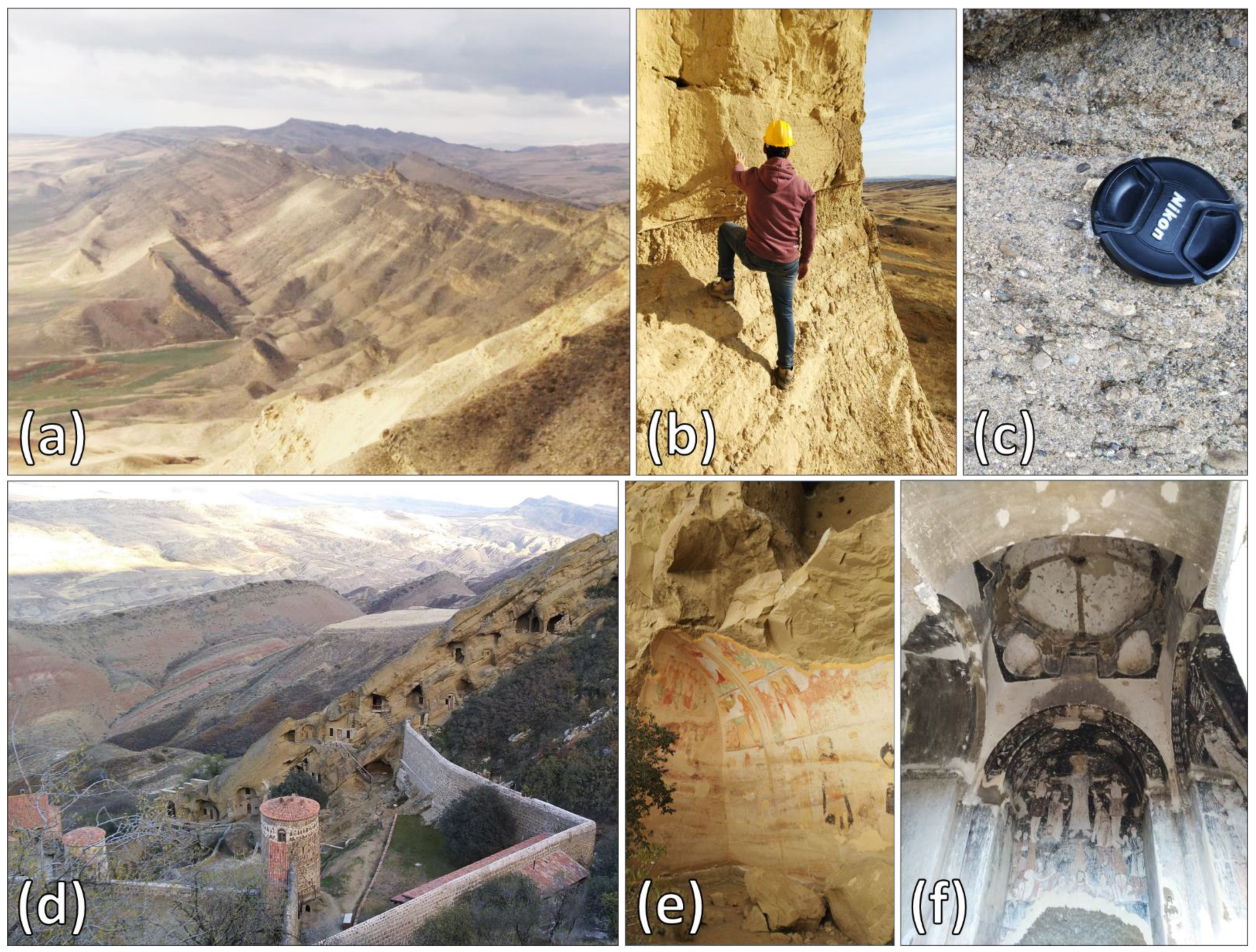
2.2. David Gareja
2.3. Uplistsikhe
2.4. The Monastery of Petra
3. Materials and Methods
3.1. Field Surveys and Geotechnical Analysis
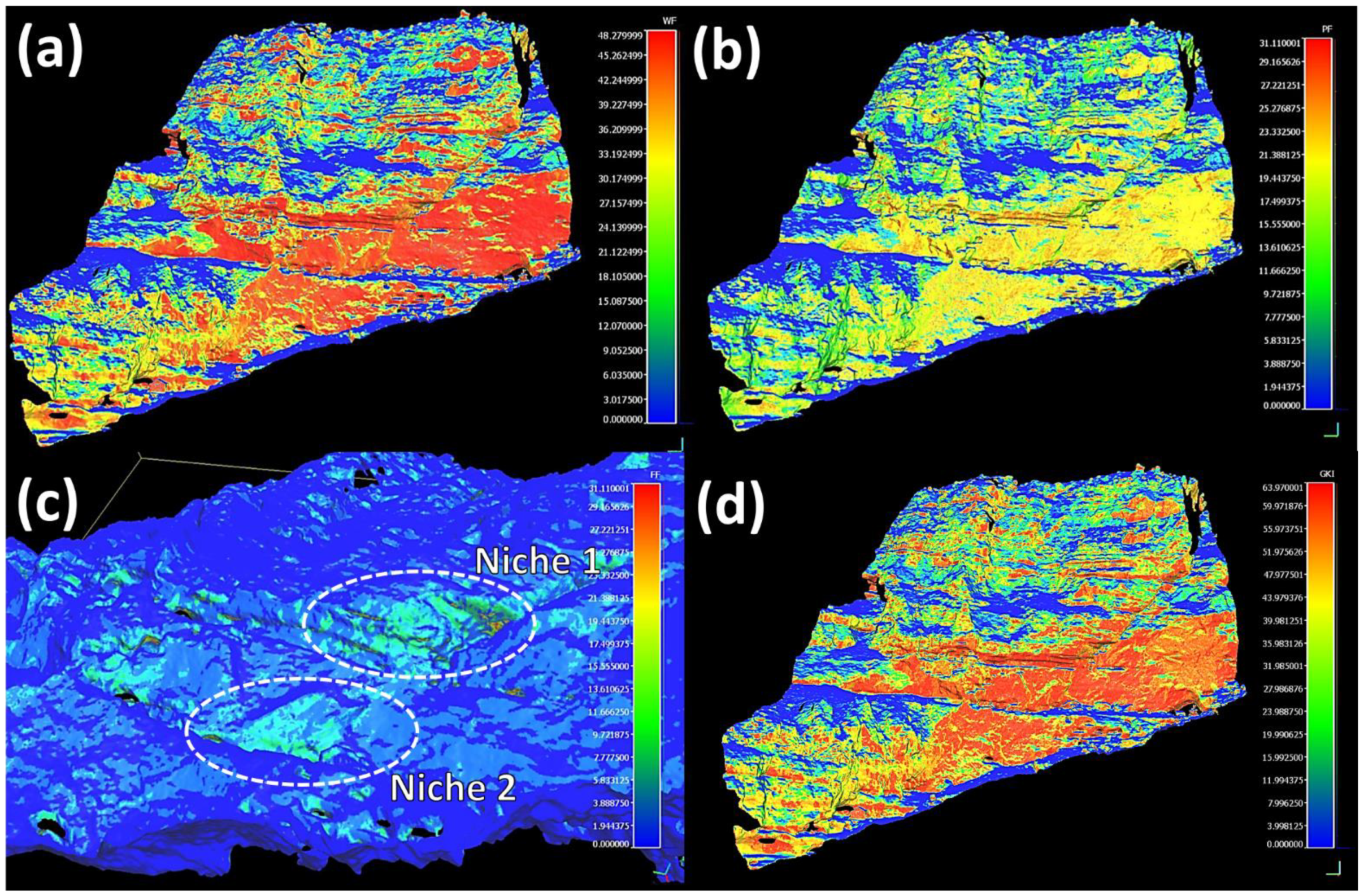
3.2. IRT Surveys
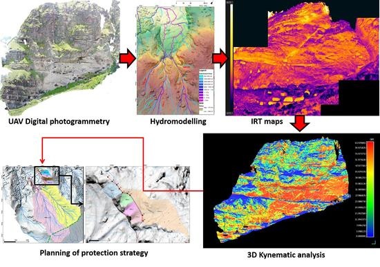
3.3. DSM Creation and Surface Runoff Modelling
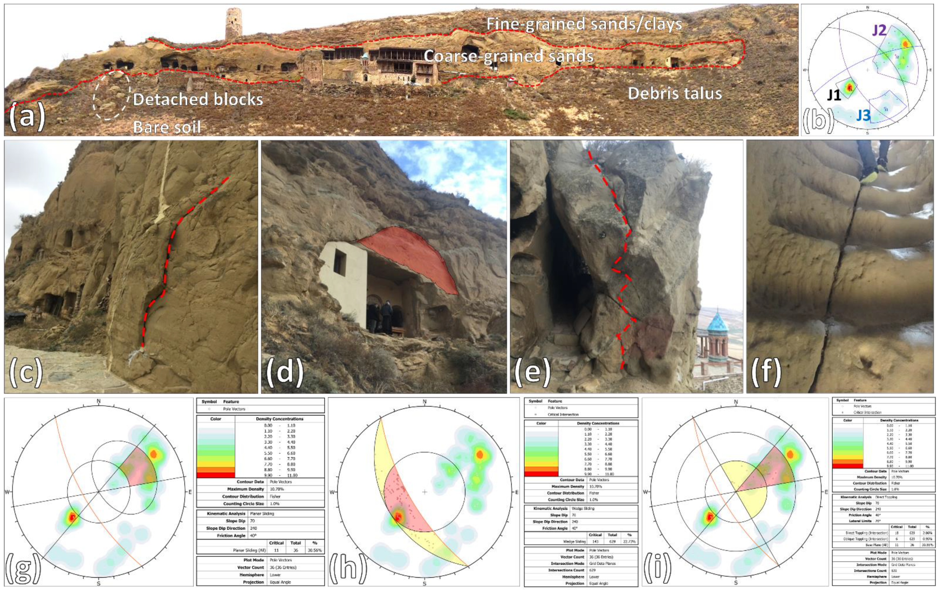
3.4. Kinematic Analysis
- (v)
- Npf = number of poles satisfying plane failure conditions.
- (vi)
- Iwf = number of intersections satisfying wedge failure conditions.
- (vii)
- Nbt = number of poles satisfying block toppling conditions.
- (viii)
- Ibt = number of intersections satisfying block toppling conditions.
- (ix)
- Nft = number of poles satisfying flexural toppling conditions.
- (i)
- Cpf = 100 × (Npf/N) for plane failure.
- (ii)
- Cwf = 100 × (Iwf/I) for wedge failure.
- (iii)
- Cbt = 100 × (Nbt/N) × (Ibt/I) for block toppling.
- (iv)
- Cft = 100 × (Nft/N) for flexural toppling.
4. Results
4.1. Geotechnical Data
4.2. Field-Remote Surveys and Kinematic Analysis
4.2.1. Vanis Kvabebi
4.2.2. David Gareja
4.2.3. Uplistsikhe
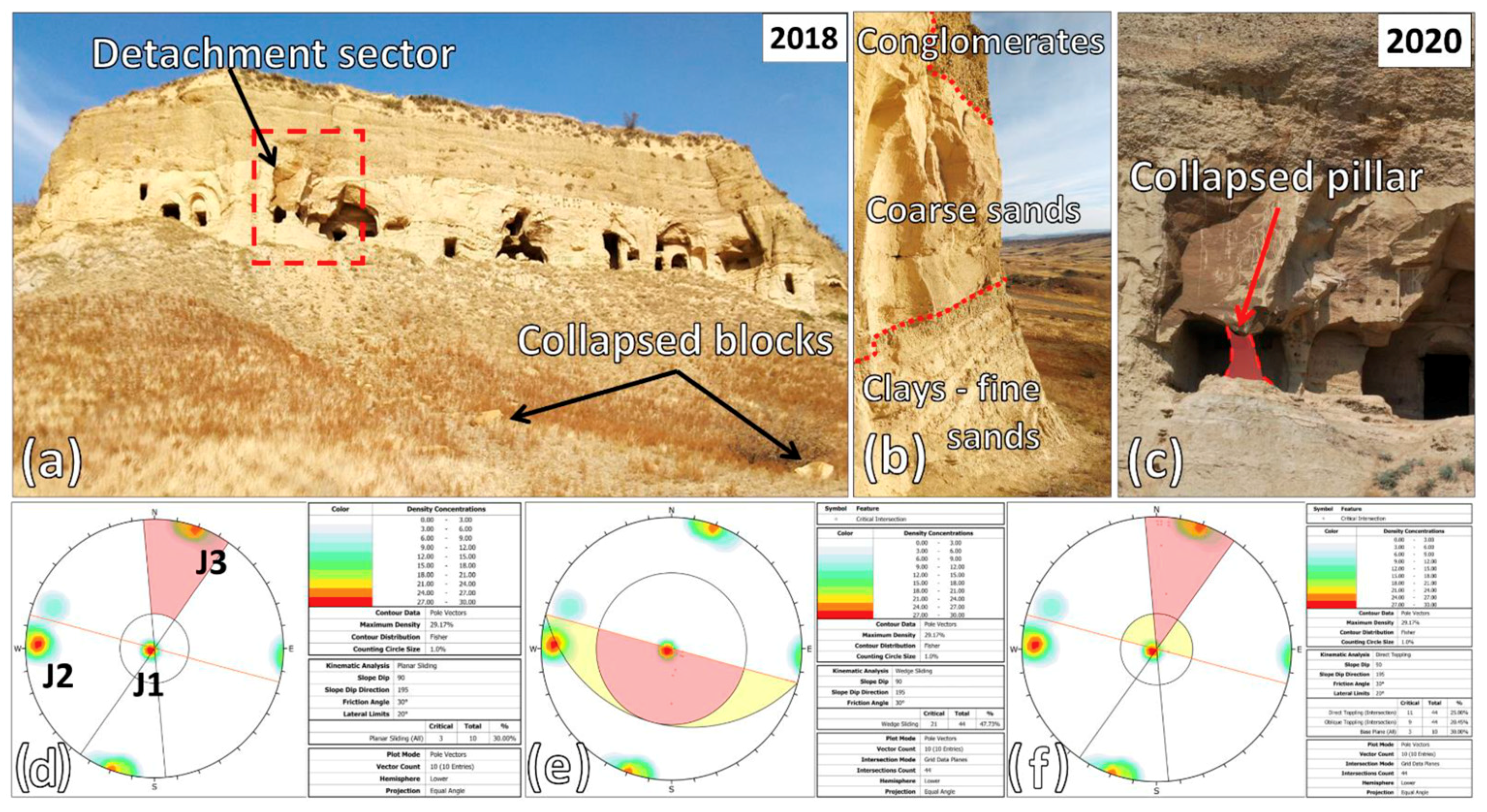
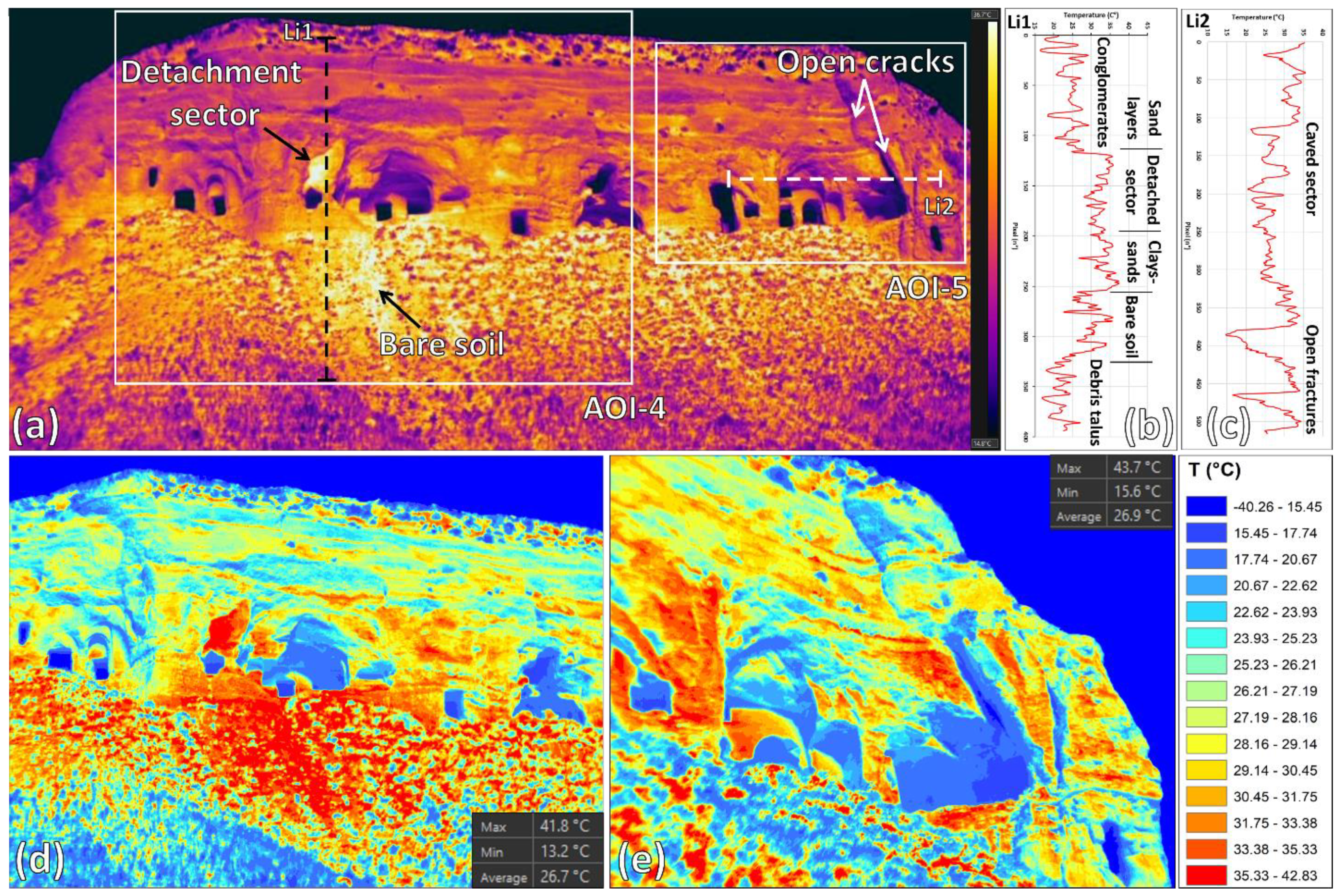
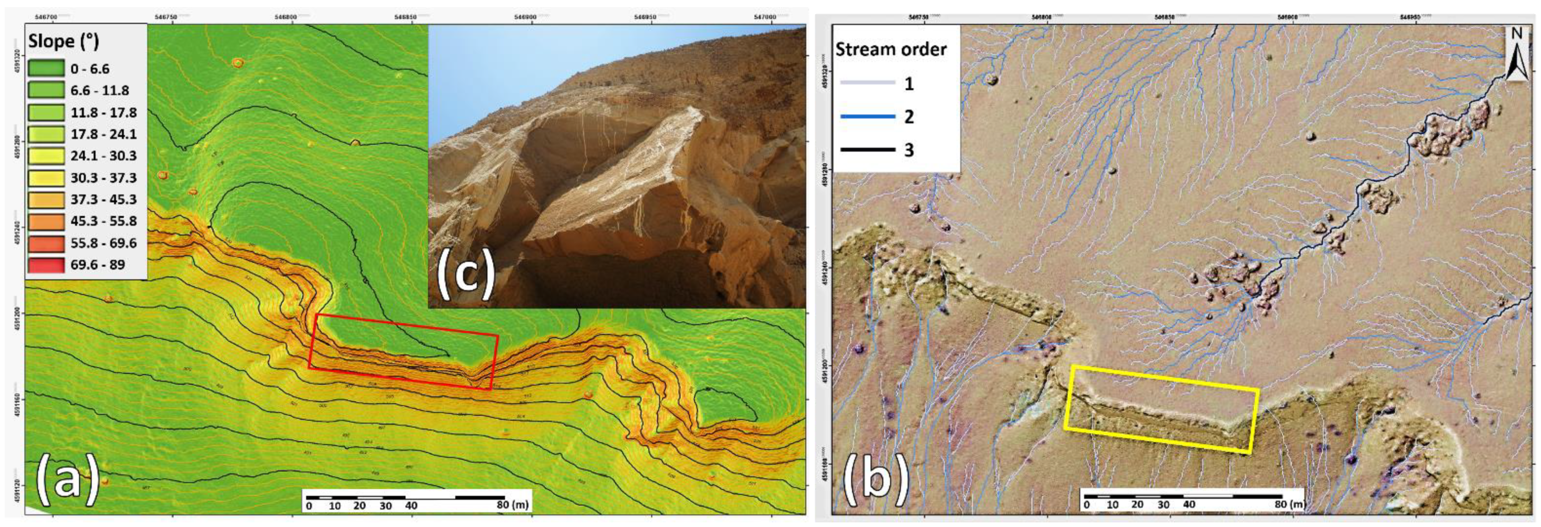
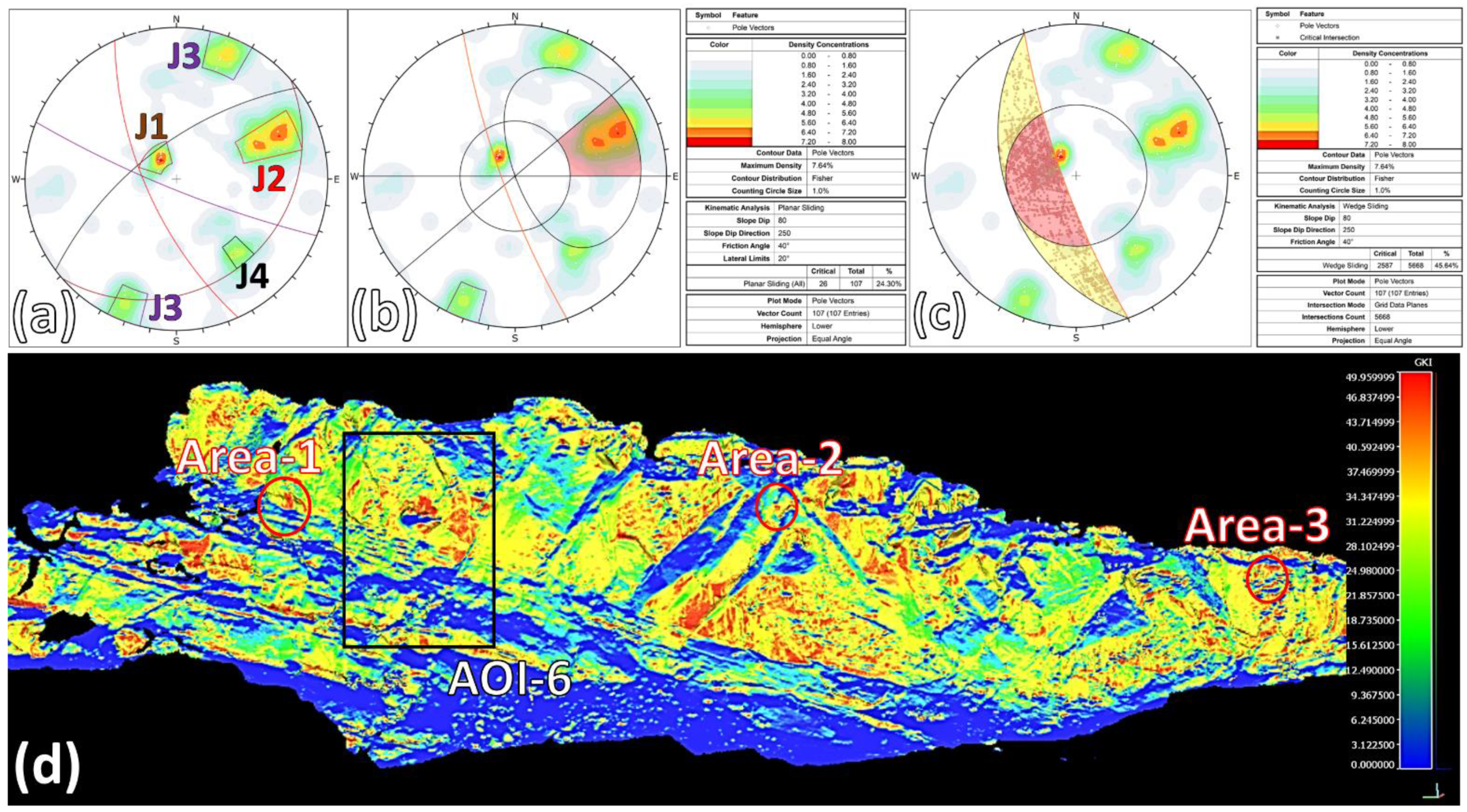
4.2.4. The Monastery in Petra
5. Discussion
5.1. Conservation Problems Affecting the Analysed Rupestrian Sites
5.2. Conservation Criticalities and Proposed Mitigation Measures
5.2.1. Vanis Kvabebi
5.2.2. David Gareja (Natlismcemeni and Sabereebi)
5.2.3. Uplistsikhe
5.2.4. The Monastery of Petra
5.3. IRT and UAV-DP for Protection/Conservation Strategies of Rupestrian Cultural Heritage
6. Conclusions
Author Contributions
Funding
Institutional Review Board Statement
Informed Consent Statement
Data Availability Statement
Acknowledgments
Conflicts of Interest
References
- Sdao, F.; Lioi, D.S.; Pascale, S.; Caniani, D.; Mancini, I.M. Landslide susceptibility assessment by using a neuro-fuzzy model: A case study in the Rupestrian heritage rich area of Matera. Nat. Hazards Earth Syst. Sci. 2013, 13, 395–407. [Google Scholar] [CrossRef] [Green Version]
- Taboroff, J. Cultural heritage and natural disasters: Incentives for risk management and mitigation. In Managing Disaster Risk in Emerging Economies; Kreimer, A., Arnold, M., Eds.; World Bank Publications, Disaster Management Risk: New York, NY, USA, 2000; Volume 2, pp. 71–79. [Google Scholar]
- Wang, J.J. Flood risk maps to cultural heritage: Measures and process. J. Cult. Herit. 2015, 16, 210–220. [Google Scholar] [CrossRef]
- Sileo, M.; Gizzi, F.T.; Donvito, A.; Lasaponara, R.; Fiore, F.; Masini, N. Multi-Scale Monitoring of Rupestrian Heritage: Methodological Approach and Application to a Case Study. Int. J. Archit. Herit. 2020, 1–16. [Google Scholar] [CrossRef]
- Timothy, P.W.; Stratulat, A.; Duffus, P.; Pre’vost, J.H.; George, W.; Scherer, W.G. Flaw propagation and buckling in clay-bearing sandstones. Environ. Geol. 2011, 63, 1565–1572. [Google Scholar]
- Banerjee, N.R.; Muehlenbachs, K. Tuff life: Bioalteration in volcaniclastic rocks from the Ontong Java Plateau. Geochem. Geophys. Geosystems 2003, 4. [Google Scholar] [CrossRef]
- Wedekind, W.; López-Doncel, R.; Dohrmann, R.; Kocher, M.; Siegesmund, S. Weathering of volcanic tuff rocks caused by moisture expansion. Environ. Earth Sci. 2013, 69, 1203–1224. [Google Scholar] [CrossRef] [Green Version]
- Ruedrich, J.; Bartelsen, T.; Dohrmann, R.; Siegesmund, S. Moisture expansion as a deterioration factor for sandstone used in buildings. Environ. Earth Sci. 2011, 63, 1545–1564. [Google Scholar] [CrossRef] [Green Version]
- Weiss, T.; Siegesmund, S.; Kirchner, D.; Sippel, J. Insulation weathering and hygric dilatation as a control on building stone degradation. Environ. Geol. 2004, 46, 402–413. [Google Scholar] [CrossRef]
- Topal, T.; Doyuran, V. Engineering geological properties and durability assessment of the Cappadocian tuff. Eng. Geol. 1997, 47, 175–187. [Google Scholar] [CrossRef]
- Boldini, D.; Guido, G.L.; Margottini, C.; Spizzichino, D. Stability analysis of a large-volume block in the historical rock-cut city of Vardzia (Georgia). Rock Mech. Rock Eng. 2018, 51, 341–349. [Google Scholar] [CrossRef]
- ISRM. Suggested methods for the quantitative description of discontinuities in rock masses. Int. J. Rock Mech. Min. Sci. Geomech. Abstr. 1978, 15, 319–368. [Google Scholar]
- Frodella, W.; Elashvili, M.; Spizzichino, D.; Gigli, G.; Adikashvili, L.; Vacheishvili, N.; Kirkitadze, G.; Nadaraia, A.; Margottini, C.; Casagli, N. Combining InfraRed Thermography and UAV Digital Photogrammetry for the Protection and Conservation of Rupestrian Cultural Heritage Sites in Georgia: A Methodological Application. Remote Sens. 2020, 12, 892. [Google Scholar] [CrossRef] [Green Version]
- Marszałek, M.; Alexandrowicz, Z.; Rzepa, G. Composition of weathering crusts on sandstones from natural outcrops and architectonic elements in an urban environment. Environ. Sci. Pollut. Res. 2014, 21, 14023–14036. [Google Scholar] [CrossRef] [Green Version]
- Pecchioni, E.; Vettori, S.; Cantisani, E.; Fratini, F.; Ricci, M.; Garzonio, C.A. Chemical and mineralogical studies of the red chromatic alteration of Florentine Pietra Serena sandstone. Eur. J. Mineral. 2016, 28, 449–458. [Google Scholar] [CrossRef]
- Margottini, C.; Gigli, G.; Ruther, H.; Spizzichino, D. Advances in Geotechnical Investigations and Monitoring in Rupestrian Settlements Inscribed in the UNESCO’s World Heritage List. Procedia Earth Planet. Sci. 2016, 16, 35–51. [Google Scholar] [CrossRef] [Green Version]
- Tunusluoglu, M.C.; Zorlu, K. Rockfall hazard assessment in a cultural and natural heritage (Ortahisar Castle, Cappadocia, Turkey). Environ. Geol. 2009, 56, 963–972. [Google Scholar] [CrossRef]
- UNESCO World Heritage List. Available online: https://whc.unesco.org/en/list (accessed on 21 January 2021).
- UNESCO Tentative List. Available online: https://whc.unesco.org/en/tentativelists (accessed on 21 January 2021).
- Margottini, C.; Antidze, N.; Corominas, J.; Crosta, G.B.; Frattini, P.; Gigli, G.; Giordan, D.; Iwasaky, I.; Lollino, G.; Manconi, A.; et al. Landslide hazard, monitoring and conservation strategy for the safeguard of Vardzia Byzantine monastery complex, Georgia. Landslides 2015, 12, 193–204. [Google Scholar] [CrossRef] [Green Version]
- Nikolakopoulos, K.; Kavoura, K.; Depountis, N.; Kyriou, A.; Argyropoulos, N.; Koukouvelas, I.; Sabatakakis, N. Preliminary results from active landslide monitoring using multidisciplinary surveys. Eur. J. Remote Sens. 2017, 50, 280–299. [Google Scholar] [CrossRef] [Green Version]
- Frodella, W.; Ciampalini, A.; Gigli, G.; Lombardi, L.; Raspini, F.; Nocentini, M.; Scardigli, C.; Casagli, N. Synergic use of satellite and ground based remote sensing methods for monitoring the San Leo rock cliff (Northern Italy). Geomorphology 2016, 264, 80–94. [Google Scholar] [CrossRef]
- Spizzichino, D.; Boldini, D.; Frodella, W.; Elashvili, M.; Margottini, C. Landslide risk analysis and mitigation for the ancient rock-cut city of Vardzia (Georgia). In Proceedings of 2017 IPL Symposium; UNESCO: Paris, France, 2017; pp. 1–8. [Google Scholar]
- Frodella, W.; Spizzichino, D.; Gigli, G.; Elashvili, M.; Margottini, C.; Villa, A.; Frattini, P.; Crosta, G.; Casagli, N. Integrating Kinematic Analysis and Infrared Thermography for Instability Processes Assessment in the Rupestrian Monastery Complex of David Gareja (Georgia). In Understanding and Reducing Landslide Disaster Risk; Springer: Cham, Germany, 2020; pp. 457–463. [Google Scholar]
- David Gareji Monasteries and Hermitages, Georgia Technical Report, The 7 Most Endangered, Europa Nostra. Campbell. 2018. Available online: https://www.europanostra.org/wp-content/uploads/2019/10/7ME-2019-Georgia-DavidGarejiMonasteries-Report.pdf (accessed on 29 January 2021).
- UNESCO World Heritage List, Petra. Available online: https://whc.unesco.org/en/list/326 (accessed on 21 January 2021).
- Lebedev, V.A.; Chernyshev, I.V.; Vashakidze, G.T.; Gudina, M.V.; Yakushev, A.I. Geochronology of Miocene volcanism in the northern part of the Lesser Caucasus (Erusheti Highland, Georgia). In Doklady Earth Sciences; Springer Science & Business Media: Berlin, Germany, 2012; Volume 444, p. 585. Available online: https://www.researchgate.net/profile/V-Lebedev-3/publication/257850126_Geochronology_of_miocene_volcanism_in_the_northern_part_of_the_Lesser_Caucasus_Erusheti_Highland_Georgia/links/00463528ef324cb0a1000000/Geochronology-of-miocene-volcanism-in-the-northern-part-of-the-Lesser-Caucasus-Erusheti-Highland-Georgia.pdf (accessed on 29 January 2021).
- Okrostsvaridze, A.; Popkhadze, N.; Bluashvili, D.; Chang, Y.H.; Skhirtladze, I. Pliocene Quaternary Samtskhe-Javakheti Volcanic Highland, Lesser Caucasus—as a result of mantle plumes activity. In Proceedings of the Fourth Plenary Conference of IGCP 610 From the Caspian to Mediterranean: Environmental Change and Human Response during the Quaternary, Tbilisi, Georgia, 2–9 October 2016; Gilbert, A.S., Yanko-Hombach, V., Eds.; Georgian National Academy of Sciences: Tbilisi, Georgia, 2016; pp. 127–131. [Google Scholar]
- Okrostsvaridze, A.; Chung, S.L.; Lin, Y.C.; Skhirtladze, I. Geology and zircon U-Pb geochronology of the Mtkvari pyroclastic flow and evaluation of destructive processes affecting Vardzia rock-cut city, Georgia. Quat. Int. 2020, 540, 137–145. [Google Scholar] [CrossRef]
- Okrostsvaridze, A.; Elashvili, M.; Nino Popkhadze, N.; Kirkitadze, G. New Data on the Geological Structure of the Vardzia Cave City, Georgia. Bull. Georgian Natl. Acad. Sci. 2016, 10, 98–106. [Google Scholar]
- Okrostsvaridze, A.; Gagnidze, N.; Bobrova, I.; Skhirtladze, I. Late Miocene volcanic ash layers of the intermountain depression of the eastern Caucasus: The product of a megacaldera explosion? In Proceedings of the Joint meeting of IGCP 610 and INQUA POCAS Focus Group, Palermo, Italy, 1–9 October 2017.
- Okrostsvaridze, A.; Popkhadze, N. Megavolcano in the Late Cenozoic Samtckhe Javakheti Volcanic Province? Lesser Caucasus, Georgia-Turkish Border. In Proceedings of the VI International Workshop on Collapse Calderas, Hokkaido, Japan, 4–10 September 2016; International Association of Volcanology and Chemistry of the Earth’s Interior: Rome, Italy, 2016; p. 42. Available online: http://eprints.iliauni.edu.ge/6373/ (accessed on 29 January 2021).
- Gamkrelidze, I.; Okrostsvaridze, A.; Gagnidze, N. Field trip guide of the fourth plenary conference. In Proceedings of the IGCP 610 “From the Caspian to Mediterranean: Environmental Change and Human Response during the Quaternary” (2013–2017), Fourth Plenary Conference and Field Trip, Tbilisi, Georgia, 2–9 October 2016. [Google Scholar]
- Margottini, C.; Spizzichino, D.; Gigli, G.; Frodella, W.; Elashvili, M.; Alberti, S.; Valagussa, A.; Crosta, G. Instability processes affecting the rupestrian monastery complex area of Davit Gareja (Georgia). In Proceedings of the International Conference: Davit Gareji, Multidisciplinary Study and Development Strategy, Tbilisi, Georgia, 18–20 April 2020; pp. 187–193. Available online: https://www.researchgate.net/profile/William-Frodella/publication/332013627_Instability_processes_affecting_the_rupestrian_monastery_complex_area_of_David_Gareja_Georgia/links/5f0f0415299bf1e548b71490/Instability-processes-affecting-the-rupestrian-monastery-complex-area-of-David-Gareja-Georgia.pdf (accessed on 29 January 2021).
- UNESCO Tentative List, David Gareja. Available online: https://whc.unesco.org/en/tentativelists/5224 (accessed on 21 January 2021).
- Stinghen, A. Tectonic and Geomorphological Evolution of the Kartalini Basin, Georgia. Master’s thesis, University of Padua, Padova PD, Italy, 2011; 109p. [Google Scholar]
- Khimshiashvili, K. The architecture of Uphlistsikhe, Georgia. Trans. Anc. Monum. Soc. 1999, 77–100. [Google Scholar]
- ICOMOS. World Report on Monuments and Sites in Danger Georgia. 2001. Available online: https://www.icomos.org/risk/2001/geor2001.htm (accessed on 4 January 2021).
- UNESCO World Heritage List, Uplistsikhe. Available online: https://whc.unesco.org/en/tentativelists/5234 (accessed on 21 January 2021).
- Alshawabkeh, Y.; Bal’awi, F.; Haala, N. 3D Digital Documentation, Assessment, and Damage Quantification of the Al-Deir Monument in the Ancient City of Petra, Jordan. Conserv. Manag. Archaeol. Sites 2010, 12, 124–145. [Google Scholar] [CrossRef]
- Margottini, C.; Spizzichino, D. Historical accesses to UNESCO cultural heritages: Engineering geology for the sustainable conservation of Petra Siq. Innov. Infrastruct. Solut. 2017, 2, 25. [Google Scholar] [CrossRef] [Green Version]
- Barjous, M.O.; Jaser, D. Geotechnical Studies and Geological Mapping of Ancient Petra City. Amman: The Hashemite Kingdom of Jordan, Ministry of Energy and Mineral Resources, Natural Resources Authority, Geology Directorate, Geological Mapping Division. 1992. Available online: https://pascal-francis.inist.fr/vibad/index.php?action=getRecordDetail&idt=6402229 (accessed on 29 January 2021).
- Bumbaru, D.; Burke, S.; Petzet, M.; Truscott, M.; Ziesemer, J. Jordan Heritage @ Risk! In Heritage at Risk, ICOMOS World Report 2000 on Monuments and Sites in Danger; ICOMOS: Munich, Germany, 2000; pp. 123–124. [Google Scholar]
- Chambel, A.; Colvin, C. A geological and hydrogeological assessment of “El Dir” monastery, Petra (Jordan). UNESCO Unpublished Report. 23 September 2010. [Google Scholar]
- Rocscience, Dips. v8 Graphical and Statistical Analysis of Orientation Data; Rocscience Inc.: Toronto, ON, Canada, 2020. [Google Scholar]
- ISRM Suggested methods for determining point load strength. Int. J. Rock Mech. Min. Sci. Geomech. 1985, 22, 51–62. [CrossRef]
- Teza, G.; Marcato, G.; Castelli, E.; Galgaro, A. IRTROCK: A matlab toolbox for contactless recognition of surface and shallow weakness traces of a rock mass by infrared thermography. Comput. Geosci. 2012, 45, 109–118. [Google Scholar] [CrossRef]
- Maldague, X. Theory and Practice of Infrared Technology for Non-Destructive Testing; John-Wiley & Sons: Hoboken, NJ, USA, 2001; 684p. [Google Scholar]
- Spampinato, L.; Calvari, S.; Oppenheimer, C.; Boschi, E. Volcano surveillance using infrared cameras. Earth-Sci. Rev. 2011, 106, 63–91. [Google Scholar] [CrossRef]
- Avdelidis, N.P.; Moropoulou, A.; Theoulakis, P. Detection of water deposits and movement in porous materials by infrared imaging. Infrared Phys. Technol. 2003, 44, 183–190. [Google Scholar] [CrossRef]
- Tavukçuoğlu, A.; Dügünes, E.N.; Caner-Saltık, Ş.; Demirci, A. Use of IR thermography for the assessment of surface-water drainage problems in a historical building, Ağzıkara-han (Aksaray), Turkey. NDT E Int. 2005, 38, 402–410. [Google Scholar] [CrossRef]
- Aggelis, D.G.; Kordatos, E.Z.; Soulioti, D.V.; Matikas, T.E. Combined use of thermography and ultrasound for the characterization of subsurface cracks in concrete. Constr. Build. Mater. 2010, 24, 1888–1897. [Google Scholar] [CrossRef]
- De Freitas, S.S.; De Freitas, V.P.; Barreira, E. Detection of façade plaster detach-ments using infrared thermography, a nondestructive technique. Constr. Build. Mater. 2014, 70, 80–87. [Google Scholar] [CrossRef]
- Cabrelles, M.; Galcerá, S.; Navarro, S.; Lerma, J.L.; Akasheh, T.; Haddad, N. Integration of 3D laser scanning, photogrammetry and thermography to record architectural monuments. In Proceedings of the 22nd CIPA Symposium, Kyoto, Japan, 11–15 October 2009. [Google Scholar]
- Frodella, W.; Gigli, G.; Morelli, S.; Lombardi, L.; Casagli, N. Landslide Mapping and Characterization through Infrared Thermography (IRT): Suggestions for a Methodological Approach from Some Case Studies. Remote Sens. 2017, 9, 1281. [Google Scholar] [CrossRef] [Green Version]
- Gigli, G.; Frodella, W.; Garfagnoli, F.; Morelli, S.; Mugnai, F.; Menna, F.; Casagli, N. 3-D geomechanical rock mass characterization for the evaluation of rockslide susceptibility scenarios. Landslides 2014, 11, 131–140. [Google Scholar] [CrossRef]
- Pappalardo, G.; Mineo, S.; Imposa, S.; Grassi, S.; Leotta, A.; La Rosa, F.; Salerno, D. A quick combined approach for the characterization of a cliff during a post-rockfall emergency. Landslides 2020, 17, 1063–1081. [Google Scholar] [CrossRef]
- Frodella, W.; Morelli, S.; Pazzi, V. Infrared Thermographic surveys for landslide mapping and characterization: The Rotolon DSGSD (Norther Italy) case study. Ital. J. Eng. Geol. Environ. 2017, 2017, 77–84. [Google Scholar]
- Di Traglia, F.; Nolesini, T.; Solari, L.; Ciampalini, A.; Frodella, W.; Steri, D.; Allotta, B.; Rindi, A.; Marini, L.; Monni, N.; et al. Lava delta deformation as a proxy for submarine slope instability. Earth Planet. Sci. Lett. 2018, 488, 46–58. [Google Scholar] [CrossRef]
- FLIR Systems Inc. FLIR ThermaCAM SC620 technical specifications. 2009. Available online: www.flir.com/cs/emea/en/view/?id=41965 (accessed on 31 July 2019).
- FLIR Systems Inc. FLIR ThermaCAM B425. 2009. Available online: http://www.thermalimagingcamera.co.uk/media/downloads/14/flir-b425-ir-camera-datasheet.pdf (accessed on 31 December 2020).
- FLIR Systems Inc. FLIR Tools+ Datasheet. 2015. Available online: https://www.infraredcamerawarehouse.com/content/FLIR%20Datasheets/FLIR%20ToolsPlus%20Datasheet.pdf (accessed on 30 September 2019).
- ESRI Inc. ArcMap 10.6 Datasheet. 2019. Available online: https://www.esri.com/content/dam/esrisites/en-us/media/pdf/product/desktop/ArcGIS-10.6-Desktop-ArcMap-Functionality-Matrix.pdf (accessed on 31 October 2019).
- Chandler, J. Effective application of automated digital photogrammetry for geomorphological research. Earth Surf. Process Landf. 1999, 24, 51–63. [Google Scholar] [CrossRef]
- Zhang, Z.; Zheng, S.; Zhan, Z. Digital terrestrial photogrammetry with photo total station. Int. Arch. Photogramm. Remote Sens. 2004, 232–236. Available online: https://citeseerx.ist.psu.edu/viewdoc/download?doi=10.1.1.58.7457&rep=rep1&type=pdf (accessed on 29 January 2021).
- Grün, A.; Remondino, F.; Zhang, L. Reconstruction of the Great Buddha of Bamiyan, Afghanistan. Int. Arch. Photogramm. Remote Sens. 2002, 34, 363–368. [Google Scholar]
- Rinaudo, F.; Chiabrando, F.; Lingua, A.; Spanò, A. Archaeological site monitoring: UAV photogrammetry can be an answer. International Archives of the Photogrammetry. Remote Sens. Spat. Inf. Sci. 2012, 39, 583–588. [Google Scholar]
- Remondino, F.; Barazzetti, L.; Nex, F.; Scaioni, M.; Sarazzi, D. UAV photogrammetry for mapping and 3d modeling–current status and future perspectives. International archives of the photogrammetry. Remote Sens. Spat. Inf. Sci. 2011, 38, C22. [Google Scholar]
- Bolognesi, M.; Furini, A.; Russo, V.; Pellegrinelli, A.; Russo, P. Accuracy of cultural heritage 3D models by RPAS and terrestrial photogrammetry. The International Archives of Photogrammetry. Remote Sens. Spat. Inf. Sci. 2014, 40, 113. [Google Scholar]
- Agisoft Photoscan, Datasheet. 2017. Available online: https://www.agisoft.com/pdf/photoscan-pro_1_4_en.pdf (accessed on 31 December 2020).
- Riegl VZ-400 Datasheet. 2017. Available online: www.riegl.com/uploads/tx_pxpriegldownloads/10_DataSheet_VZ-400_2017-06-14.pdf (accessed on 31 December 2020).
- Hoek, E.; Bray, J.W. Rock Slope Engineering, 3rd ed.; Institute of Mining and Metallurgy: London, UK, 1981. [Google Scholar]
- Goodman, R.E.; Bray, J.W. Toppling of rock slopes. In Proceedings of the ASCE Specialty Conference on Rock Engineering for Foundations and Slopes, Boulder, CO, USA, 15–18 August 1976; Volume 2, pp. 201–234. Available online: https://ci.nii.ac.jp/naid/10004542689/ (accessed on 29 January 2021).
- Hudson, J.A.; Harrison, J.P. Engineering Rock Mechanics; Pergamon Press: Oxford, UK, 1997; p. 444. [Google Scholar]
- Casagli, N.; Pini, G. Analisi cinematica della stabilità di versanti naturali e fronti di scavo in roccia. Geol. Appl. E Idrogeol. 1993, 28, 223–232. (In Italian) [Google Scholar]
- Lombardi, L. Nuove Tecnologie di Rilevamento e di Analisi di Dati Goemeccanici per la Valutazione della Sicurezza. Unpublished Ph.D. Thesis, University of Florence, Piazza di San Marco, Firenze, Italy, 2007. (In Italian). [Google Scholar]
- Gigli, G.; Frodella, W.; Mugnai, F.; Tapete, D.; Cigna, F.; Fanti, R.; Intrieri, E.; Lombardi, L. Instability mechanisms affecting cultural heritage sites in the Maltese Archipelago. Nat. Hazards Earth Syst. Sci. 2012, 12, 1–21. [Google Scholar] [CrossRef] [Green Version]
- Gigli, G.; Casagli, N. Semi-automatic extraction of rock mass structural data from high resolution LIDAR point clouds. Int. J. Rock Mech. Min. Sci. 2011, 48, 187–198. [Google Scholar] [CrossRef]
- DGM, AB, RM (2015) CloudCompare-User’s Manual for version 2.6.1. Available online: https://www.danielgm.net/cc/doc/qCC/CloudCompare%20v2.6.1%20-%20User%20manual.pdf (accessed on 21 December 2020).
- Boldini, D.; Wang, F.; Sassa, K.; Tommasi, P. Mechanism of landslide causing the December 2002 tsunami at Stromboli volcano (Italy). In Landslides; Springer: Berlin/Heidelberg, Germany, 2005; pp. 173–180. [Google Scholar]
- Rotonda, T.; Tommasi, P.; Boldini, D. Geomechanical characterization of the volcaniclastic material involved in the 2002 landslides at Stromboli. J. Geotech. Geoenvironmental Eng. 2009, 136, 389–401. [Google Scholar] [CrossRef]
- Spizzichino, D.; Margottini, C. Evidences on the Groundwater seepage nearby the monument “El Deir” or “Monastery”, at the ancient city of Petra; Internal Report; Superior Institute for Protection and Environmental Research (ISPRA): Rome, Italy, 2014. [Google Scholar]
- Dixon, J.B.; Weed, S.B. Minerals in Soil Environments, 2nd ed.; Soil Science Society of America: Madison, WI, USA, 1989; p. 1244. [Google Scholar]
- Heinrichs, K. Diagnosis of Weathering Damage on Rock-Cut Monuments in Petra, Jordan. Environ. Geol. 2008, 56, 643–675. [Google Scholar] [CrossRef]
- Nichols, G. Sedimentology and Stratigraphy, 2nd ed.; Wiley-Blackwell: Oxford, UK, 2009. [Google Scholar]
- Verezen, V.A.M. The Crumbling Wonder: A damage-and risk-assessment of sandstone monuments and natural features in the Petra Archaeological Park (Jordan). Int. J. Stud. Res. Archaeol. 2017, 3, 20–34. [Google Scholar]
- Eklund, S. Stone Weathering in the Monastic Building Complex on Mountain of St Aaron in Petra, Jordan. Unpublished Master’s Thesis, University of Helsinki, Department of Archaeology, Helsinki, Finland, 2008. Available online: https://oa.doria.fi/bitstream/handle/10024/43682/stonewea.pdf?sequence=1 (accessed on 8 December 2020).
- Ortloff, C.R. The Water Supply and Distribution System of the Nabataean City of Petra (Jordan), 300 BC–AD 300. Camb. Archaeol. J. 2005, 15, 93–109. [Google Scholar] [CrossRef]
- US-ICOMOS Jordan. US-ICOMOS Management Analysis and Recommendations for the Petra World Heritage Site; Report; US-ICOMOS: Amman, Jordan, 1996. [Google Scholar]
- Climate Engine. Available online: https://clim-engine-development.appspot.com (accessed on 20 January 2021).


| Case Study | Thermal Camera | Camera Resolution (pix) | Field of View (°) | Survey Period | Slope Aspect | Sensor-Target Distance (m) | Image Resolution (cm) | Air Temperature (C°)—Relative Humidity (%) |
|---|---|---|---|---|---|---|---|---|
| Vanis Kvabebi | FLIR SC620 | 640 × 480 | 24 × 18 | November 2018 | W/E | 100 | 6.6 | 14.4–63.4 |
| Natlismcemeli | FLIR SC620 | 640 × 480 | 24 × 18 | November 2018 | S | 110/20 | 7.1/1.2 | 13.4–65.9 |
| Sabereebi | FLIR SC620 | 640 × 480 | 24 × 18 | November 2018 | SW | 100/20 | 6.5 | 22.6–39.8 |
| Uplistsikhe | FLIR SC620 | 640 × 480 | 24 × 18 | November 2018 | SW | 100 | 6.6 | 21.3–33.6 |
| Petra | FLIR B425 | 320 × 240 | 25 × 19 | June 2014 | SW | 20 | 2.6 | 26–21 |
| Digital Cameras | Sensor Accuracy (‘’) | Pixels (M) | Field of View (°) | Lens (mm) | Measurement Range (m) |
|---|---|---|---|---|---|
| DJI Phantom 4Pro | 1 | 20 | 84 | 35 | 1 m–∞ |
| DJI Mavic Pro 2 | 1 | 20 | 77 | 28 | 1 m–∞ |
| Laser Scanner | Accuracy (mm) | Divergence (mrad) | Resolution (arcsec) | Angular step (°) | Measurement range (m) |
| Z-400 | 5 mm | 0.3 | 1.8 arcsec | 0.0024°–0.288° | 1.5–280 |
| Study site DSM-Orthophoto resolution (cm) | Vanis Kvabebi (10-5) | Natlismcemeli (8-4) | Sabereebi (9-4.5) | Uplistsikhe (7-3.5) |
| Case Study | Friction Angle (°) | Uniaxial Compressive Strength (MPa) | Unit Weight (KN/m3) |
|---|---|---|---|
| Vanis Kvabebi | 28° | 2.70 | 16.76 |
| Natlismcemeli | 27° | 0.49 | 16.56 |
| Sabereebi | 23° | 0.52 | 15.09 |
| Uplistsikhe | 40 | 3.55 | 19.5 |
Publisher’s Note: MDPI stays neutral with regard to jurisdictional claims in published maps and institutional affiliations. |
© 2021 by the authors. Licensee MDPI, Basel, Switzerland. This article is an open access article distributed under the terms and conditions of the Creative Commons Attribution (CC BY) license (http://creativecommons.org/licenses/by/4.0/).
Share and Cite
Frodella, W.; Elashvili, M.; Spizzichino, D.; Gigli, G.; Nadaraia, A.; Kirkitadze, G.; Adikashvili, L.; Margottini, C.; Antidze, N.; Casagli, N. Applying Close Range Non-Destructive Techniques for the Detection of Conservation Problems in Rock-Carved Cultural Heritage Sites. Remote Sens. 2021, 13, 1040. https://0-doi-org.brum.beds.ac.uk/10.3390/rs13051040
Frodella W, Elashvili M, Spizzichino D, Gigli G, Nadaraia A, Kirkitadze G, Adikashvili L, Margottini C, Antidze N, Casagli N. Applying Close Range Non-Destructive Techniques for the Detection of Conservation Problems in Rock-Carved Cultural Heritage Sites. Remote Sensing. 2021; 13(5):1040. https://0-doi-org.brum.beds.ac.uk/10.3390/rs13051040
Chicago/Turabian StyleFrodella, William, Mikheil Elashvili, Daniele Spizzichino, Giovanni Gigli, Akaki Nadaraia, Giorgi Kirkitadze, Luka Adikashvili, Claudio Margottini, Nikoloz Antidze, and Nicola Casagli. 2021. "Applying Close Range Non-Destructive Techniques for the Detection of Conservation Problems in Rock-Carved Cultural Heritage Sites" Remote Sensing 13, no. 5: 1040. https://0-doi-org.brum.beds.ac.uk/10.3390/rs13051040