
Multitemporal InSAR Coherence Analysis and Methods for Sand Mitigation


Dipartimento di Elettronica, Informazione e Bioingegneria (DEIB), Politecnico di Milano, Via Giuseppe Ponzio 34/5, 20133 Milan, Italy
*
Author to whom correspondence should be addressed.
Remote Sens. 2021, 13(7), 1362; https://0-doi-org.brum.beds.ac.uk/10.3390/rs13071362
Submission received: 23 February 2021
/
Revised: 29 March 2021
/
Accepted: 31 March 2021
/
Published: 2 April 2021
Abstract
:Dunes and sand sheets motion natural hazard affect many desertic areas worldwide and require careful assessment to develop effective mitigation plans to protect populated sites, infrastructure, and human activities. The study explores the suitability of Synthetic Aperture Radar (SAR) coherent methods to detect desert area instabilities and estimate sand accumulations displacements. The SAR methods have been applied to long time series of images provided by Sentinel-1. Moreover, the research introduces a novel robust index, named Temporal Stability Index, able to characterize the percentage of stability of a target with time. The work reports the experiments performed on the United Arab Emirates (UAE) and Egypt desertic areas and proves the usefulness of SAR coherent methods to support sand mitigation measures.

1. Introduction
In several desert areas, instabilities due to dunes and sand sheets movements represent a significant threat to transportation, urban areas, and human activities [1,2,3]. Proper planning and implementation of risk mitigation measures require an in-depth knowledge of dunes structure and information about migration rates. Among the existing methods for detecting and tracking dunes movements, wide-coverage satellite images have increasingly become valuable resources that extend investigations, previously based on local-scale surveys, to larger areas [4]. In particular, the opening of satellite image archives and, in recent years, the free availability of regular time series of data provided by the Sentinel constellation of the European Space Agency (ESA) gave a significant boost to research.
Most of the works in the literature which investigate dunes dynamic evolution are performed on optical satellite data. Beneficial information is derived from multi-temporal optical images through classic visual interpretation and analysis [5,6] or more sophisticated techniques based on imagery cross-correlation [7,8,9].
Although it is less used in sand mitigation context, SAR (Synthetic Aperture Radar) can undoubtedly give a valuable and complementary contribution as the nature of its observation is different from that of optical systems; while the optical methods provide good sensitivity to discriminate sand by its ‘color’, the radar senses the sand by its penetration depth. In fact, the electromagnetic wave can penetrate the sub-surface over a dry medium for depth from centimeters to many meters (in C band), depending on the medium compactness [10,11].
This means that the two approaches are consistent in detecting dunes, intended as the accumulation of sand subject to instability due to wind effect. However, the optical measures also detect very thin layers of sand sheets, negligible for sand mitigation purposes, which are instead totally transparent to radar.
Moreover, compared to optical observations, SAR data do not suffer from issues related to different illumination or weather conditions: the radar itself brings the illumination, and, since it works at radio frequency, it is immune to cloud coverage. Like any coherent acquisition system, SAR is characterized by sub-centimetric sensitivity to changes in the scene geometrical structure [12].
As previously mentioned, the literature related to the use of SAR imagery for dune and sand sheets motion investigation is not so broad. Most of the references use interferometric SAR coherence [13], a standard measure of SAR that corresponds to the linear correlation coefficient between two coregistered, complex SAR images. The absolute value of coherence, normalized in [0,1], is susceptible to the scene’s stability.
Coherence changes have been adopted for sensing even slight changes in the desert areas of Niger and Algeria [10,14]. In [15], a coherent change detection approach is used in the desert of Egypt to identify migrating sand dunes not recognizable on Sentinel-2 optical data. In [16], the mapping of mobile dunes in Kuwait is performed using speckle filtering and a multi-resolution coherence image.
The mentioned studies, although proving how coherence provides valuable insights on desert instabilities, suffer from the limitation to consider very few image pairs. This is partly due to the lack of data, as the SAR-based missions have long been characterized by very high revisiting time (e.g., ERS1/2, Envisat, Radarsat, JERS). It is worth noting that only since 2014–2016, the Sentinel-1 satellites are in orbit and guarantee the free availability of ubiquitous time series of SAR data, with a nominal revisiting frequency of up to 1–3 days [17].
The present work aims to exploit coherent methods on the now available long time series of SAR images. This implies the generation of stacks of coherence images which can cause issues for their interpretation. To overcome this problem, two very intuitive and easy-to-compute coherence-based indexes, i.e., Mean Short-Term Coherence (MSTC) and Temporal Stability Index (TSI), are proposed for instabilities characterization. Of particular interest is the TSI, which has been conceived to provide information about the percentage of stability over time, essential information to support sand mitigation planning in intermittent stability environments such as deserts.
Together with SAR coherence-based indexes, the long time series of images have also been exploited for estimation of sand accumulations displacements. To this purpose, the offset tracking technique, which, in a similar way of optical, optimizes the cross-correlation between patches extracted from different images [18,19,20,21,22], has been applied to the SAR image stack.
The remainder of the article is organized as follows. The following section describes the main characteristics of the selected use cases, i.e., the desert areas of Egypt and United Arab Emirates (UAE), the Sentinel-1 datasets adopted for the study, and the applied SAR methods. Section 3 presents the outcomes, while in Section 4, SAR methods’ advantages and drawbacks are discussed. Finally, the last section outlines the main conclusions.
2. Materials and Methods
2.1. Use Cases Characterization and Datasets
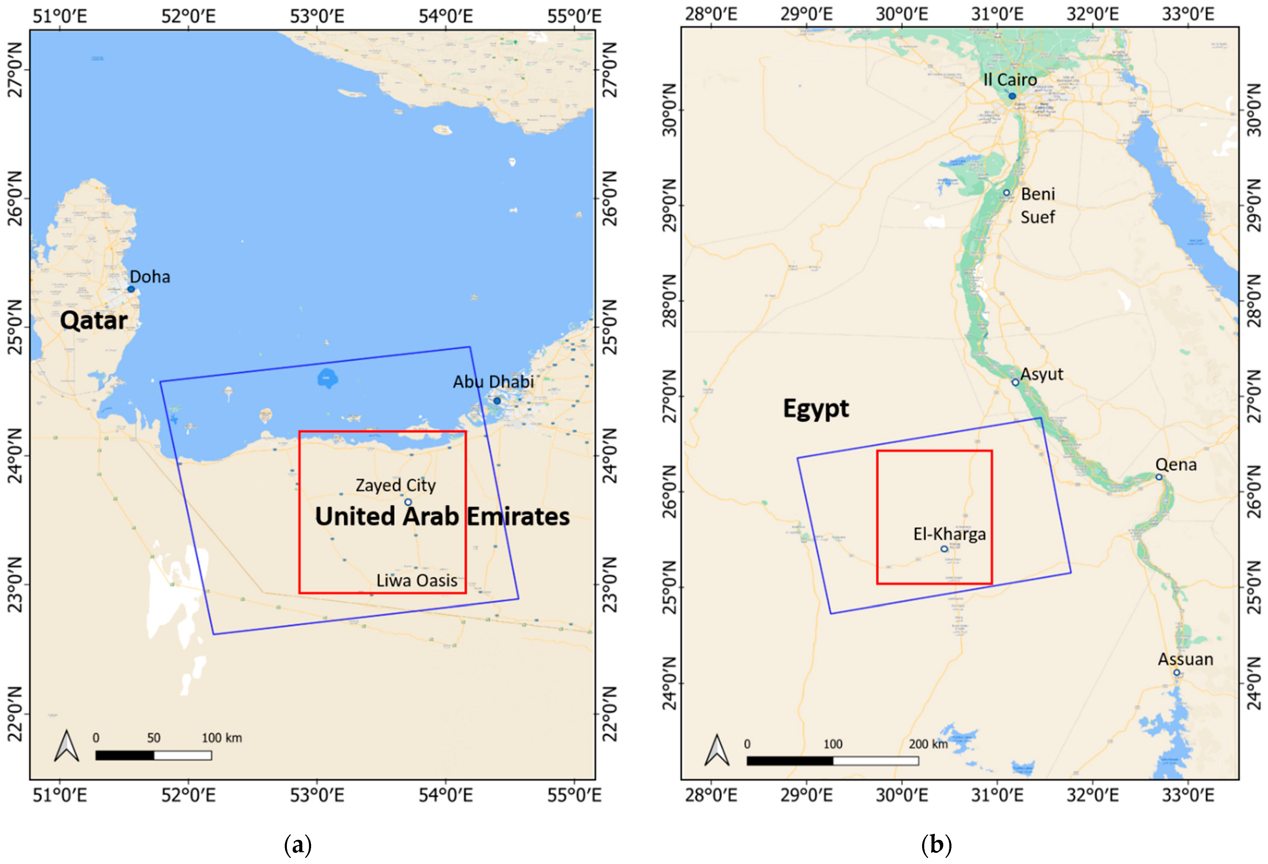
The two selected use cases are located in the desert areas of the UAE and Egypt, respectively; the regions of interest (ROIs) are outlined with red boxes in Figure 1.
The UAE ROI extends from the Arabian Gulf coast to the northern part of Liwa Oasis. Most of the surface is sand desert characterized by heterogeneous type and size of dunes [23]: the small dunes of the coastal region, the small-to-medium dunes in the Zayed City surroundings, and the large mega-barchan dunes of the Liwa Oasis, which reach heights up to 160 m [24]. From the climate side, the UAE is dominated by a dry hot climate with sporadic precipitations, about 40 mm/year in Liwa [25], occurring mainly in winter. The predominant wind direction is from N–NW to S–SE. Still, the presence of seasonal and occasional wind variations can significantly affect the pattern and shape of the smaller dunes [24,26]. Frequent occurrence of sand encroachment phenomena threatening transportation networks, urban areas, and cultivated fields in UAE region is reported by literature [27].
The ROI selected for Egypt is located in the central area of the country, and it is part of the Western Desert, which is characterized by sandy dunes and sheets, rocky plateaus, depressions, and plains [28]. According to [29], the 27% of the Western Desert area is covered by sand deposits.
Annual rainfall is very sporadic within the area of interest (just a few millimeters), and prevailing winds blow from N–NW directions, although seasonal wind variations can be observed [2,30]. Of particular interest is the El-Kharga depression, where linear and barchan (crescentic) dunes motion threatens monumental sites, roads, and agricultural fields. These instabilities are documented in the literature. In [2], optical satellite images analysis highlighted a dunes advance ranging from 55 to 128 m between 1987 and 2000. Recent research on some crescentic dunes in the Oasis surroundings estimated a motion rate that varies from 0.5 to 14 m per year [30].
Regarding the SAR images dataset used in the study, Figure 1 shows the footprints of the Sentinel-1 frames (blue boxes) which ensure the use cases areas coverage; the frames belonging to ascending relative orbits 28 and 131 were selected for UAE and Egypt, respectively. It is worth noting that, for each frame, only the sub-swath IW2, which can cover most of the ROI, has been processed.
The present work considers all the images acquired by Sentinel-1A and Sentinel-1B satellites in the time frame 2015–2018. While for the years 2015 and 2016, the data does not have a regular revisiting time, for the years 2017 and 2018, the images are always characterized by a temporal baseline of 12 days. The data collection phase, performed through the Alaska Satellite Facility Data Search platform (https://search.asf.alaska.edu; accessed on 31 March 2021), led to 65 images for UAE and 74 for Egypt. Since both the stacks consist of a massive number of images, Level-0 RAW images were preferred to the Level-1 SLC (Single Look Complex) as their smaller size makes the downloading faster. This implies an additional step in the pre-processing aimed at raw to SLC conversion. For more detailed information about the collected images, refer to Table 1.
2.2. Methods
Dune/sand instabilities have been investigated through different measures obtained from applying SAR techniques to the image stacks; in detail, the coherence-based MSTC and TSI indexes and offsets estimations have been considered. Moreover, a proper pre-processing phase preceded the computation of these measures.
In the following, a comprehensive description of each stage of the work, outlined in Figure 2, is proposed. It is worth noting that most of the steps, highlighted with blue boxes in the diagram, have been performed by taking advantage of existing tools in the free and open-source software SNAP (Sentinel Application Platform) provided by ESA (https://step.esa.int/main/toolboxes/snap/; accessed on 31 March 2021).
2.2.1. Pre-Processing
The pre-processing procedure, proposed in Figure 2, aims to obtain a coregistered stack of SLC SAR images, an essential requirement for applying all the selected techniques.
Firstly, Level-0 (raw) products are converted into Level-1 SLC by a procedure called focusing. Once the SLC dataset is available, the coregistration is obtained by aligning all the images to a selected reference one with sub-pixel accuracy [31]. Moreover, as burst-mode acquisitions characterize Sentinel-1, proper debursting is needed to join all bursts into a single image [32]. Finally, interferometric pre-processing is needed to calibrate the phases properly [33].
The contribution of phase is critical for estimating sub-centimetric terrain changes. Since the phase senses the radar-to-target distance, a phase variation indicates the movement of the target. The InSAR technique [13] computes this variation by a phase difference between coregistered complex radar observations acquired in the same area at different times. Figure 3 depicts a SAR interferometric system typical geometry, where the target P is imaged by radar passes at different times t, t+1, …, t+n from a slightly different look angle.
Considering two acquisitions at times t and t+1, the interferometric process allows obtaining the difference between radar/target distance rt and radar/target distance rt+1. It is worth noting that this difference results from the contribution of different factors: a possible displacement of the target; a local topography-related effect due to differences in sensor positions during the acquisitions; and changes in atmospheric conditions of ionospheric and tropospheric layers, which can cause a delay in the propagating radar wave.
The activities here presented aim to detect the target displacements; thus, the last step of pre-processing consists of removing all the other contributions. The topographic phase is compensated using an existing Digital Elevation Model (DEM), like the Shuttle Radar Topography Mission (SRTM) (http://srtm.csi.cgiar.org/ accessed on 31 March 2021) proposed by SNAP software, and precise orbit information. Regarding the removal of effects due to atmospheric conditions changes, the literature proposes well-established methods [34,35]. However, these effects are significant if global scale phenomena are considered; as this work focuses on a local-scale analysis, the atmospheric phase compensation is not applied.
2.2.2. TSI and MSTC Indexes
The MSTC and the novel TSI are derived from the coherence. Coherence is defined as the linear correlation coefficient between two complex SLC images. Given the two observations, xm and xn, of the same target located in P, the coherence is estimated using spatial averaging as proposed in (1):
where * indicates the complex conjugate, and i,j represents the row and column indices of the spatial estimation windows. The absolute value of the coherence, , ranges in the interval [0,1] and indicates the scene stability. = 1 means that the scene is stable, therefore the two observations are linearly dependent; if = 0, the two observations of the target are independent; 0 < < 1 indicates that some dependence between the observations exists.
If stacks of multi-temporal coregistered SAR images are available, a mean value of coherence over the whole considered period, i.e., the MSTC index (), can be estimated. The procedure for computation is proposed in Figure 2. Firstly, the absolute value of the coherence for each pair of SAR images at the shortest temporal baseline is calculated. Then, the geocoding is applied. Lastly, the temporal average of the geocoded images is performed according to (2):
where P is the target, N the total number of images, and the geocoded absolute value of coherence computed between two temporally consecutive images.
Being a simple temporal average of coherence values, the MSTC cannot provide information about the frequency of changes in stability occurring over time in a specific area. For example, suppose that MSTC provides a moderate value of coherence for a particular site. In that case, there is no possibility to understand if the area was moderately stable for all the considered time or if the area was stable for a limited period and then unstable for the remaining time. It is worth noting that such intermittent stability conditions are very common in desert areas, where the seasonal changes of wind direction can significantly affect dune shape and migration.
The TSI index has been conceived to fill this information gap by providing the percentage of a target’s stability over time. As shown in Figure 2, its computation includes all the MSTC steps; in addition, a further step, which precedes the temporal averaging, is introduced to discriminate non-correlated targets based on a threshold value identifying the noise. Once is estimated [12], each image is classified by assigning value 1 (stability) to pixels with values greater than , and value 0 (instability) to the remaining pixels.
The TSI index can be expressed as the average of the thresholded, short-term coherence images :
being [ ] the ceiling operator. This index is characterized by values ranging in the interval [0,1] and can be interpreted as follow: a TSI equal to 1 means that the target has always remained reasonably stable (say, above threshold) during the timespan considered; a TSI less than 1 indicates that instability occurred in some epochs. The more the TSI approaches 0, the more the target’s stability has been limited to a short period. A TSI equal to 0 means that the changes of the spatial (geometrical) structure of the dune have been continuous over time.
2.2.3. Offset Tracking
The rationale of SAR offset tracking matches the concept of coregistration through coherence maximization. Given two SAR images xm and xn, a patch surrounding (and including) a dune is extracted from each of them. The patch extracted from xn is then shifted by a fraction of the pixel size. Hence, the coherence between the two patches is computed. This process, named local cross-correlation analysis, is repeated with different shifts, in both directions, up to a prefixed displacement threshold. After that, the shift that shows the highest coherence is selected and stored.
When two images are coregistered at the sub-pixel level, in fact, their coherence is at the maximum: the measure of interest is, therefore, the displacement that guarantees the maximization of the coherence.
The process is repeated for every couple of images in the interferometric stack. In a dataset of N images, just N−1 movements may happen, but if we consider all the N(N−1)/2 couples in the stack, we compute about N2/2 shifts. An overdetermined system is then solved to robustly and accurately estimate the set of N−1 shifts that fits the best the data.
3. Results
3.1. TSI and MSTC Indexes
This section presents the MSTC and TSI indexes obtained from the stacks of pre-processed images (Section 2.2.1). Besides this, the interferometric phase is also discussed for validation purposes.
3.1.1. UAE
The 64 coherence images for the UAE were generated by applying a spatial estimation window of 120 m in range and 170 m in azimuth and then geocoded into a 20 m × 20 m geographical grid.
MSTC and TSI indexes have been derived from coherence images according to the procedure described in Section 2.2.2. Both the indexes confirm the sand encroachment issues reported by the literature (Section 2.1).
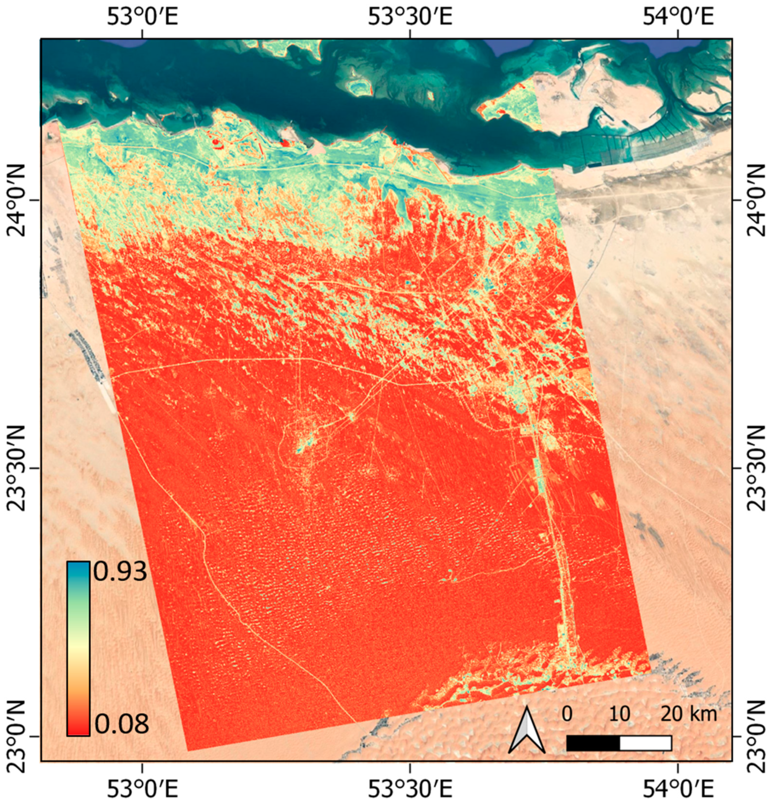
The MSTC index (Figure 4), computed as proposed in (2), shows low coherence values (red color) in most of the region of interest, thus suggesting that instability or shallow stability characterized the desert over the considered years (2015–2018). The few high coherence values (green/blue color) indicate the presence of some stable zones, which correspond to transport infrastructures (main road and highways) and populated areas. Among them, the coastal region (in the north), Zayed city (in the north-east), and Liwa Oasis (in the south-east) can be cited. It is worth noting that while the high coherence areas are described with detailed color graduation, the MSTC index gives insufficient information in the low coherence areas, which are characterized by a uniform red color.
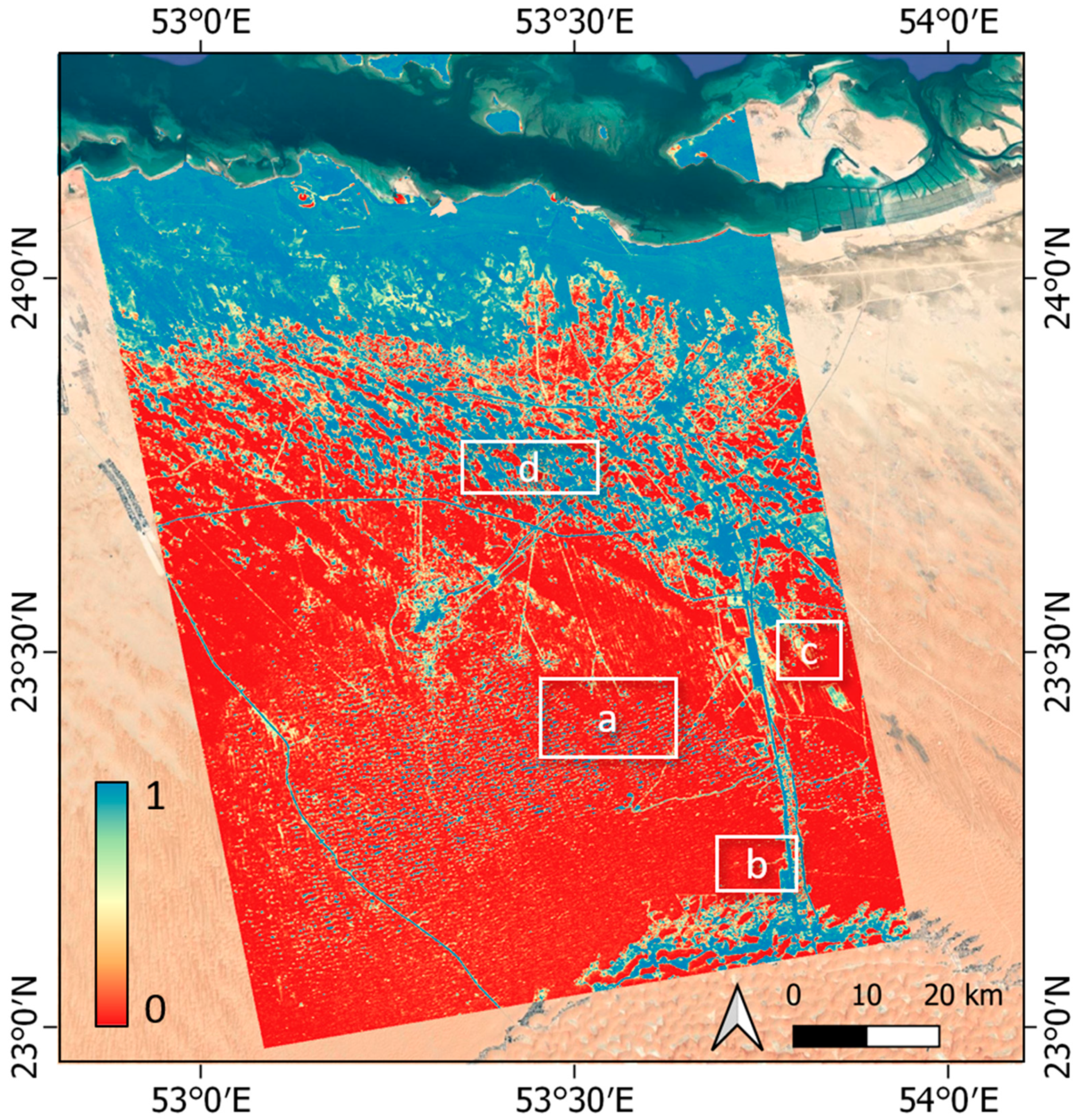
The TSI index (Figure 5) is computed as proposed in (4) by setting the threshold value (corresponding to the noise) to 0.2. According to the index definition, high values of TSI (blue color) identify areas that remained stable for all the considered time (2015–2018), while very low values of TSI (red color) indicate areas partially or totally unstable. Compared to the MSTC, the TSI shows an opposite behavior by providing more detail in low coherence areas rather than high coherence ones. In this way, the difference between totally unstable and partially unstable regions is enhanced.
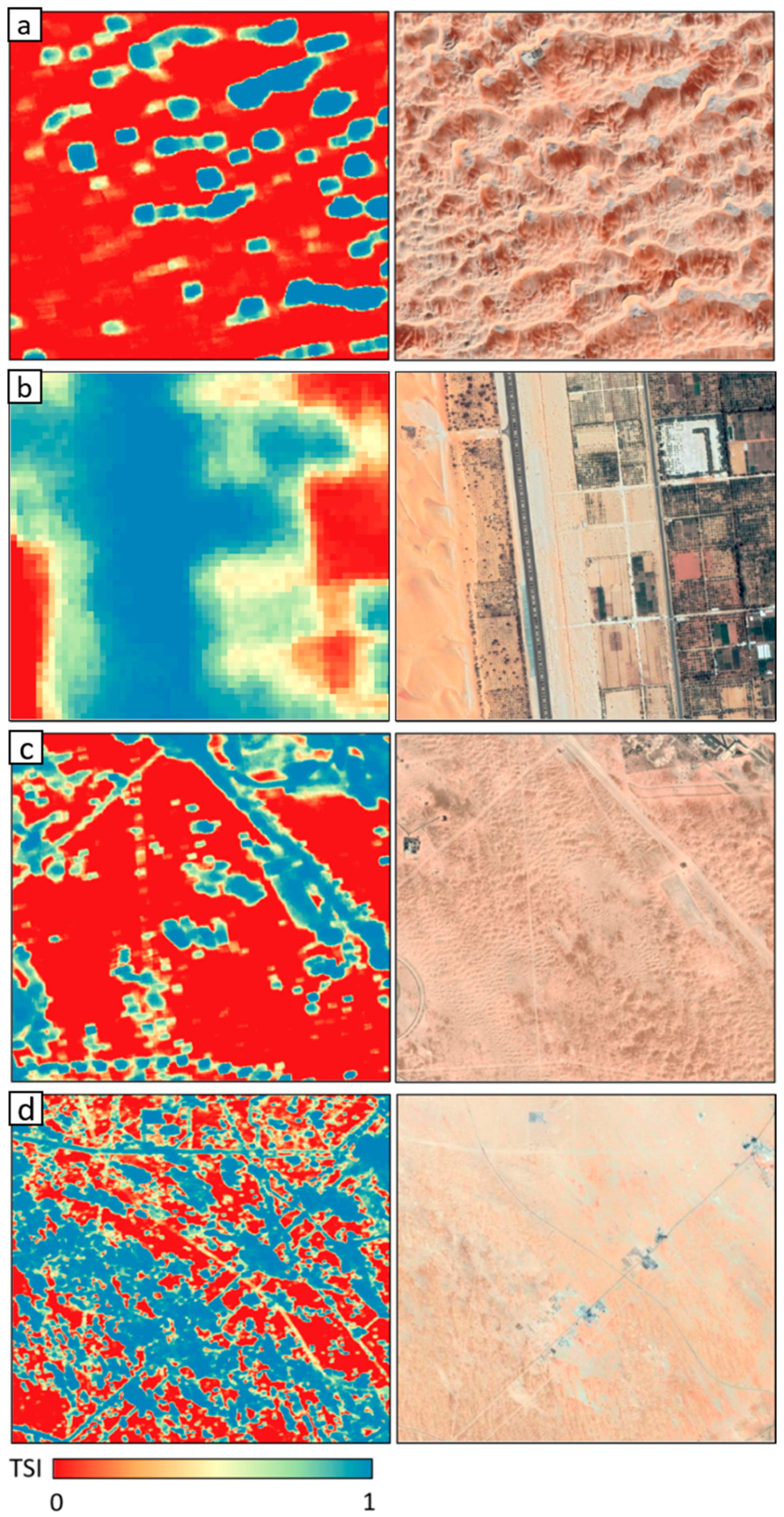
Since heterogeneous zones characterize the use case area, a further investigation at a local-scale has been performed on TSI behavior to identify the stability in space and time of different sub-areas of interest. The selected sub-areas are outlined in Figure 5 and reported in detail, together with the corresponding high-resolution satellite optical image, in Figure 6.
The sub-area a shows very stable zones (blue color, TSI equal to 1); although these areas present a similarity in shape with dunes, the analysis of the Google satellite image referred to the year 2019 suggests that they are rocky structure. The red color characterizing the surrounding terrain indicates high or total instability due to the sand sheets’ continuous movements.
A very high instability characterizes the sub-area b, which is affected by significantly sand sheet movements over the considered years. This is confirmed by the Google satellite image (a zoom is proposed in Figure 6b), which shows sand covering the forest areas close to the road.
While the sub-area c shows a few stable structures surrounded by totally unstable areas, high TSI values can be identified in the sub-area d, where stable structures, like roads, are easily recognizable.
In addition to the capability to characterize the stability over time and space of sites, the TSI was investigated to verify its suitability in identifying possible stability behavior trends in the four selected sub-areas. Specifically, the variation over the years of the total number of pixels equal to 1 (i.e., stable), available in each thresholded, short term coherence, , defined in (3), was computed and plotted on a logarithmic scale (Figure 7). Results show, especially for sub-area a (cyan line) and sub-area c (black line), a peak of stability during the winter seasons. This suggests some seasonal trends, maybe due to strong winds or rain events, which need to be further explored.
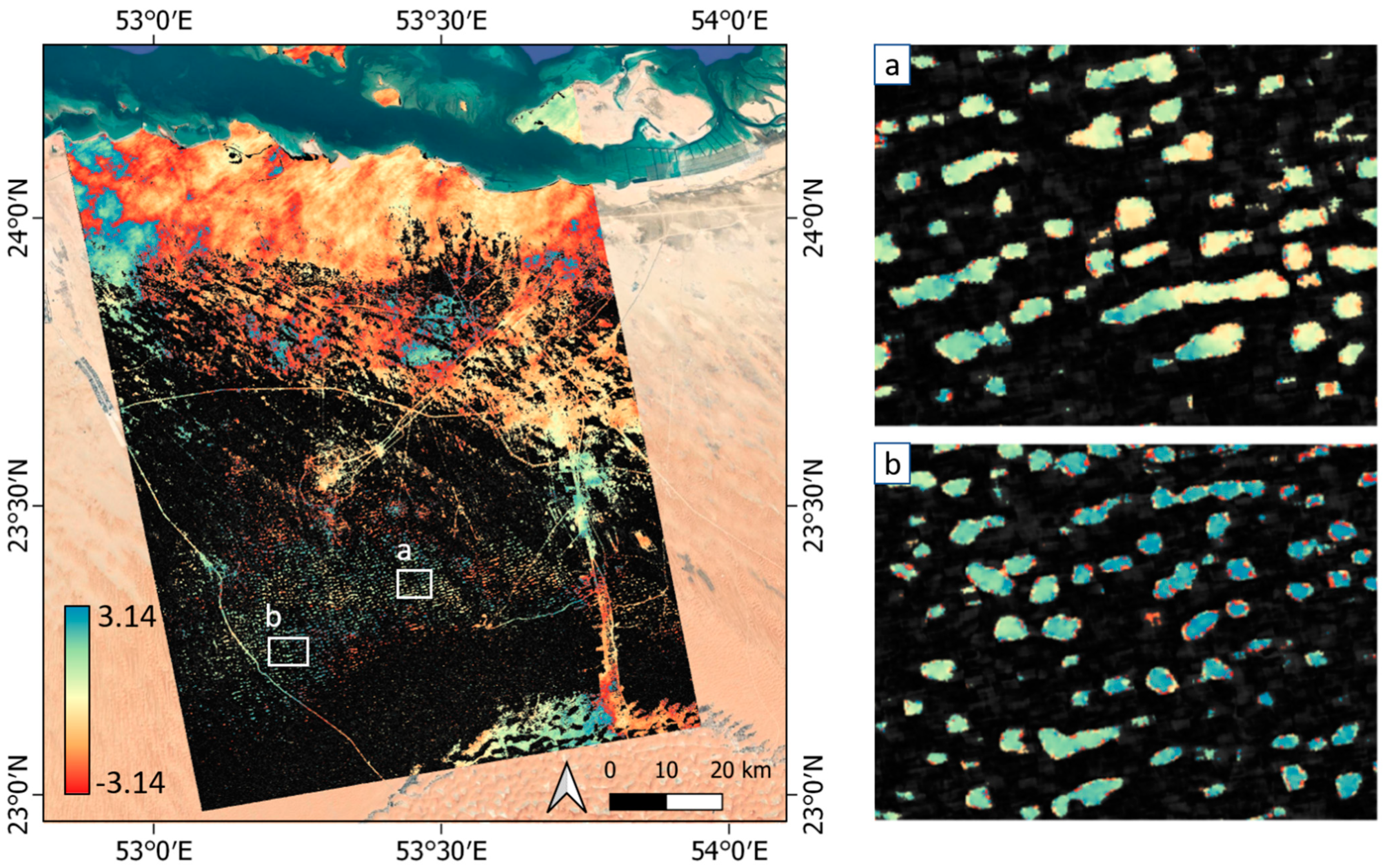
For verification purposes, interferometric phase maps were generated by applying the interferometric technique to each pair of coregistered images characterized by the shortest temporal baseline. To display only the reliable interferometric phase values, pixels having an absolute value of coherence lower than the noise threshold, i.e., 0.2, have been masked. Within this section, the interferometric phase map computed between 3 November 2018 and 15 November 2018 is proposed (Figure 8) and discussed; the same outcomes were obtained from the analysis of the other maps.
At the global scale, the scene shows smooth variations of the phase, typically accounting for some cm of overall displacement over hundreds of km. These effects are primarily due to atmospheric variations between the two acquisitions, particularly to the random fluctuations of water vapor.
Considering the local-scale, which is the scale more suitable for this research activity, a focus was performed on the two sub-areas a and b outlined in the global scale map. The interferometric phase shows in both cases uniform color or a color jump (from red to blue color) due to phase values close to π, meaning that no displacements of thick sand/dune can be identified.
3.1.2. Egypt
The 73 coherence images for the Egypt use case were generated by applying a spatial estimation window of 45 m in range and 65 m in azimuth. After processing, the images were geocoded into a 20 m × 20 m geographical grid.
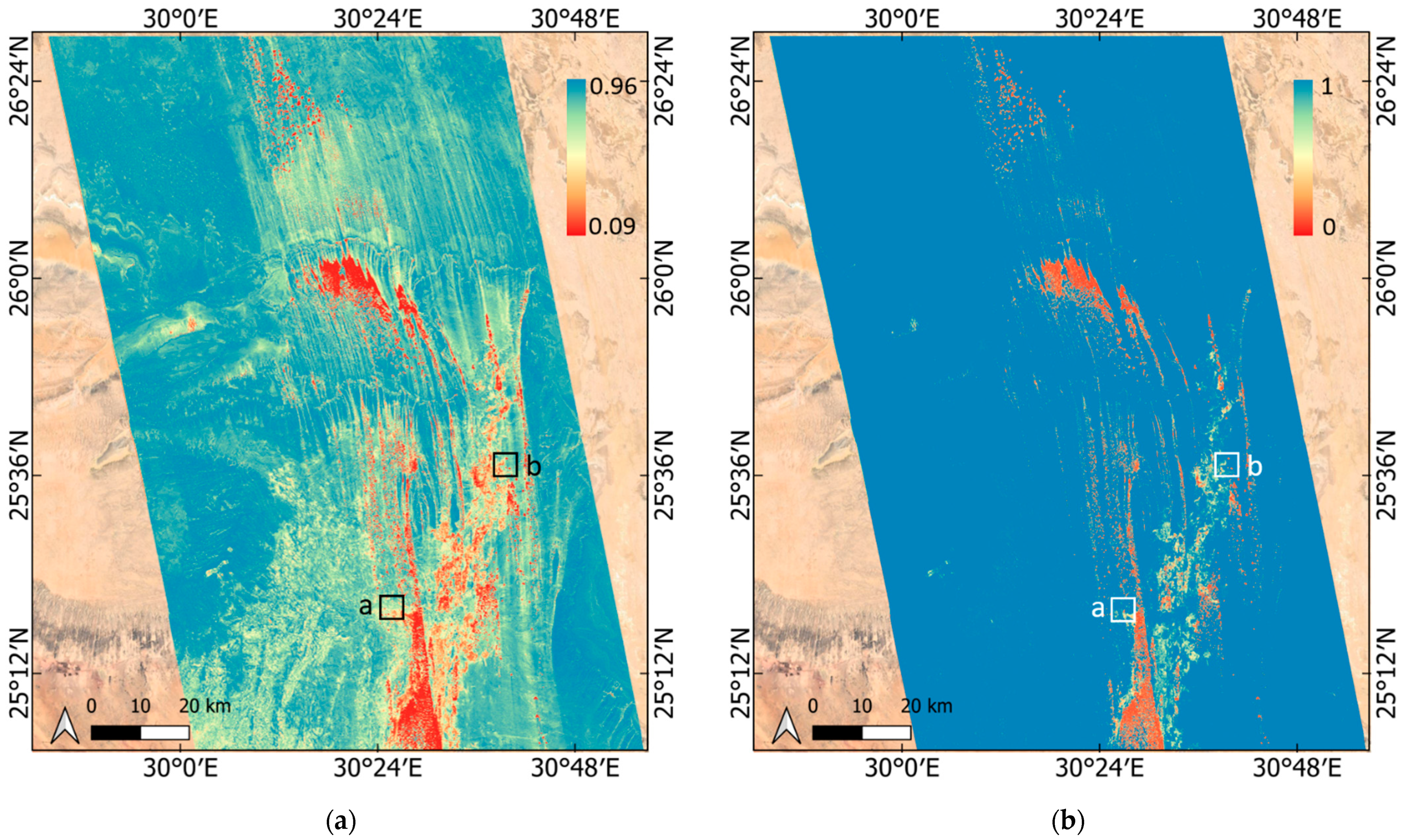
The MSTC index, resulting from the average of the absolute values of coherence images as defined in (2), is proposed in Figure 9a. The image clearly shows that the region is mainly characterized by high coherence values (green/blue color), i.e., high stability, over the considered years (2015–2018). Some exception is represented by few limited areas where structures at low coherence (red color) are visible.
Compared to MSTC, the TSI index (Figure 9b), computed as proposed in (4), is more precise in identifying the decorrelating targets giving maps that neatly define the few unstable structures. As expected based on available literature (Section 2.1), instabilities are mostly located in the surroundings of the El-Kharga Oasis.
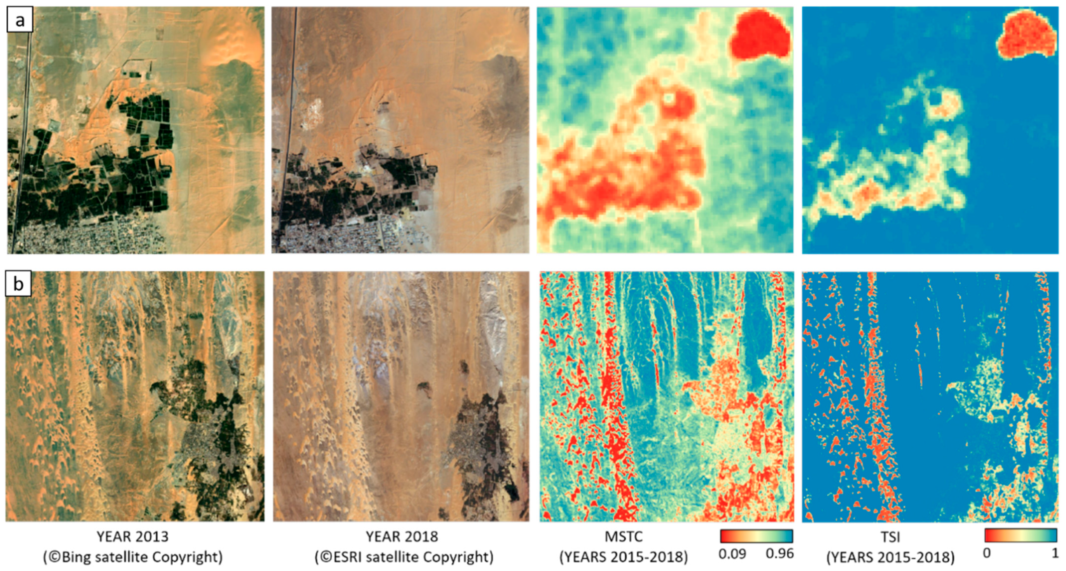
A deeper understanding of low coherence areas has been obtained through a local-scale analysis on the two sub-areas a and b, outlined in Figure 9, located to the west and north-east, respectively, of El-Kharga oasis. Figure 10 shows the corresponding MSTC and TSI index maps. Two high-resolution optical images referred to years 2013 and 2018 are also reported to provide general information about the area changes.
Images clearly show that low coherence areas in TSI and MSTC maps correspond to cultivated fields completely disappeared between 2013 and 2018 because of sandy dunes advancement. Besides, unstable barchan and linear dunes can be easily recognizable in the maps, meaning that low coherences also represent a proxy for sandy dunes.
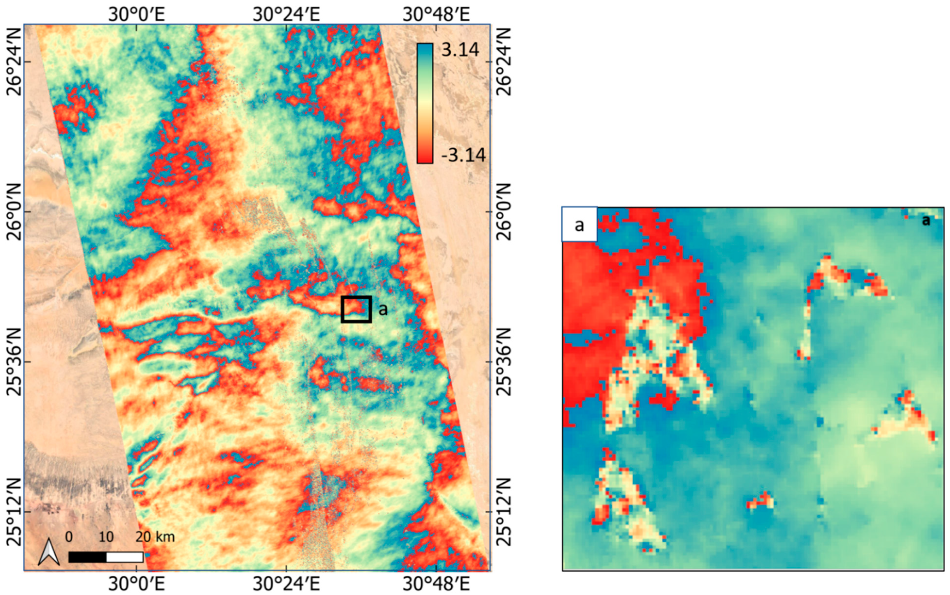
The observed dune displacements were finally verified by studying the interferometric phase. For this purpose, the interferometric technique was applied to each pair of coregistered images characterized by the shortest temporal baseline.
Figure 11 presents the phase map computed between 25 June 2018 and 7 July 2018. On the left, the global-scale map shows the effects of atmospheric/ionospheric contribution; on the right, a focus on the barchan dunes located in the north-east area of El-Kharga confirms the presence of displacements, as already detected by MSTC and TSI techniques. In particular, few cycles (one or two) in 12 days, i.e., less than 6 cm in the line of sight (LOS) direction, can be observed.
3.2. Offset Tracking
The offset tracking was tested on the unstable sandy dunes of Egypt. The offset tracking outcomes are presented in this section and compared with results obtained by feature tracking based on very high-resolution optical images.
3.2.1. SAR Offset Tracking
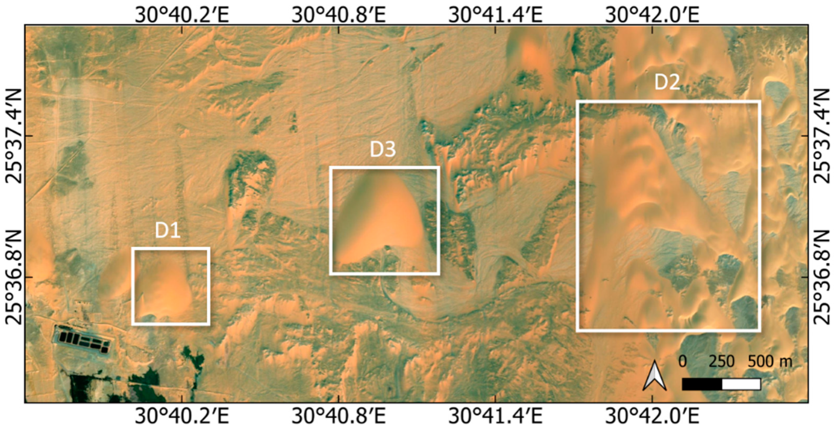
The SAR offset tracking was tested on several dunes: results are here reported in the case of the three barchan dunes named D1, D2, and D3 located just at north-east of the El-Kharga Oasis and highlighted in Figure 12. A stable rocky target D4 was also selected a few kilometers from the Oasis to verify the procedure’s goodness. The analysis was carried out on the whole stack of images defined in Table 1. Thus, for each dune, the relative displacements of all the 74 × 73/2 = 2701 image pairs were estimated and regressed for the 73 displacements, one for epoch, relative to the first image.
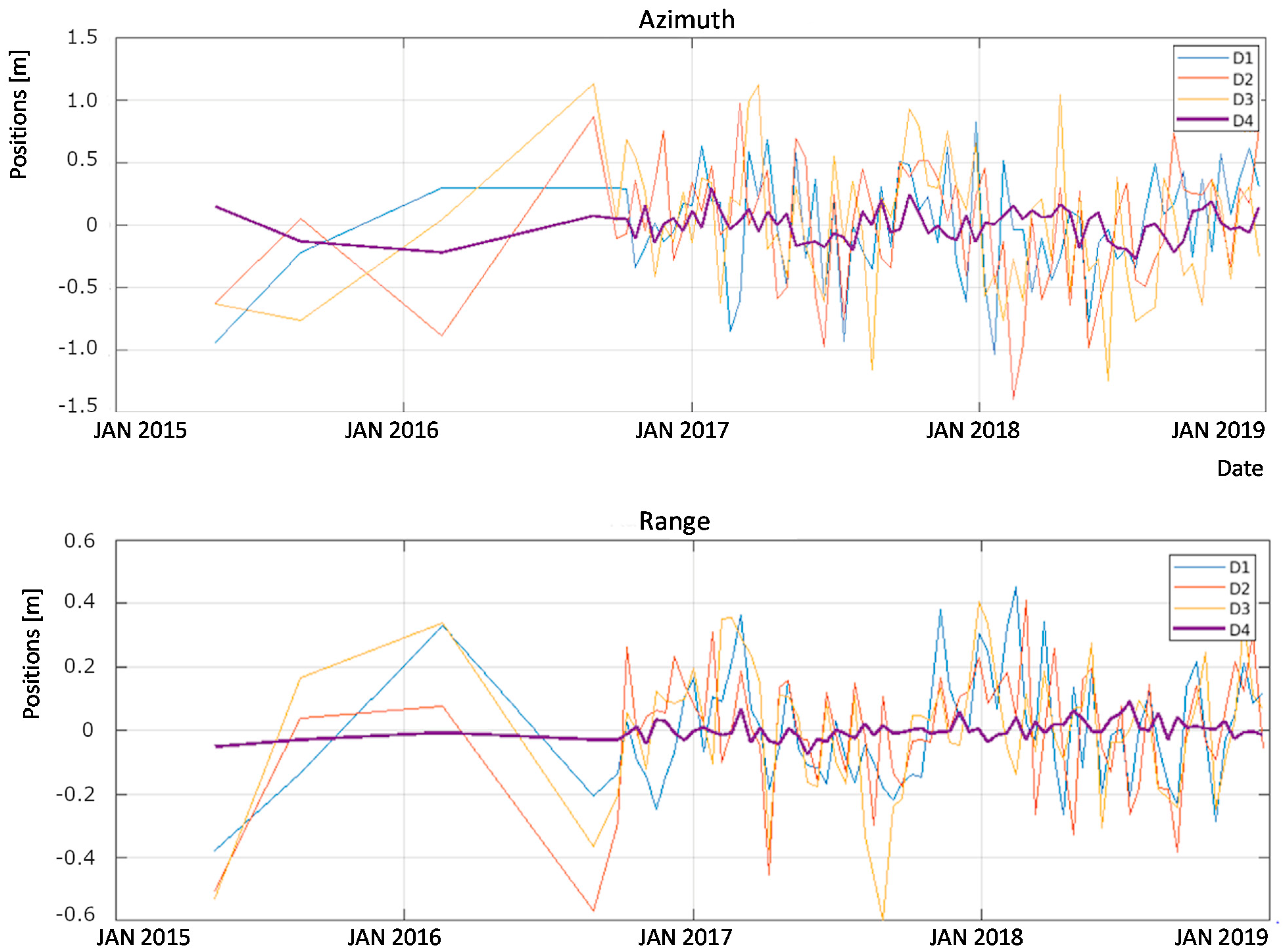
The displacements estimated along range and azimuth are proposed in Figure 13, while Figure 14a proposes the average 2D ground track of the dunes across the whole 2015–2018 period.
The evidence is a random walk of the same order of magnitude for all three dunes. The control target, D4, is stable within tens of centimeters, which matches the accuracy estimated and plotted in Figure 14b. The walk is primarily developed along azimuth, which is close to the north-south direction, with a slightly longer extension southward. This behavior confirms the one expected by observing the dune shape and is consistent with the wind regime discussed in Section 2.1. The tracks of the three dunes show a southward migration of 0.5 m on average, with peaks up to 1.5 m, a result quantitative consistent with the one reported in the literature (Section 2.1).
3.2.2. Comparison with Feature Tracking from Very High-Resolution Images
A feature tracking was implemented basing on two very high-resolution optical satellite images taken in July 2013 (provided by Bing) and in December 2018 (provided by ESRI).
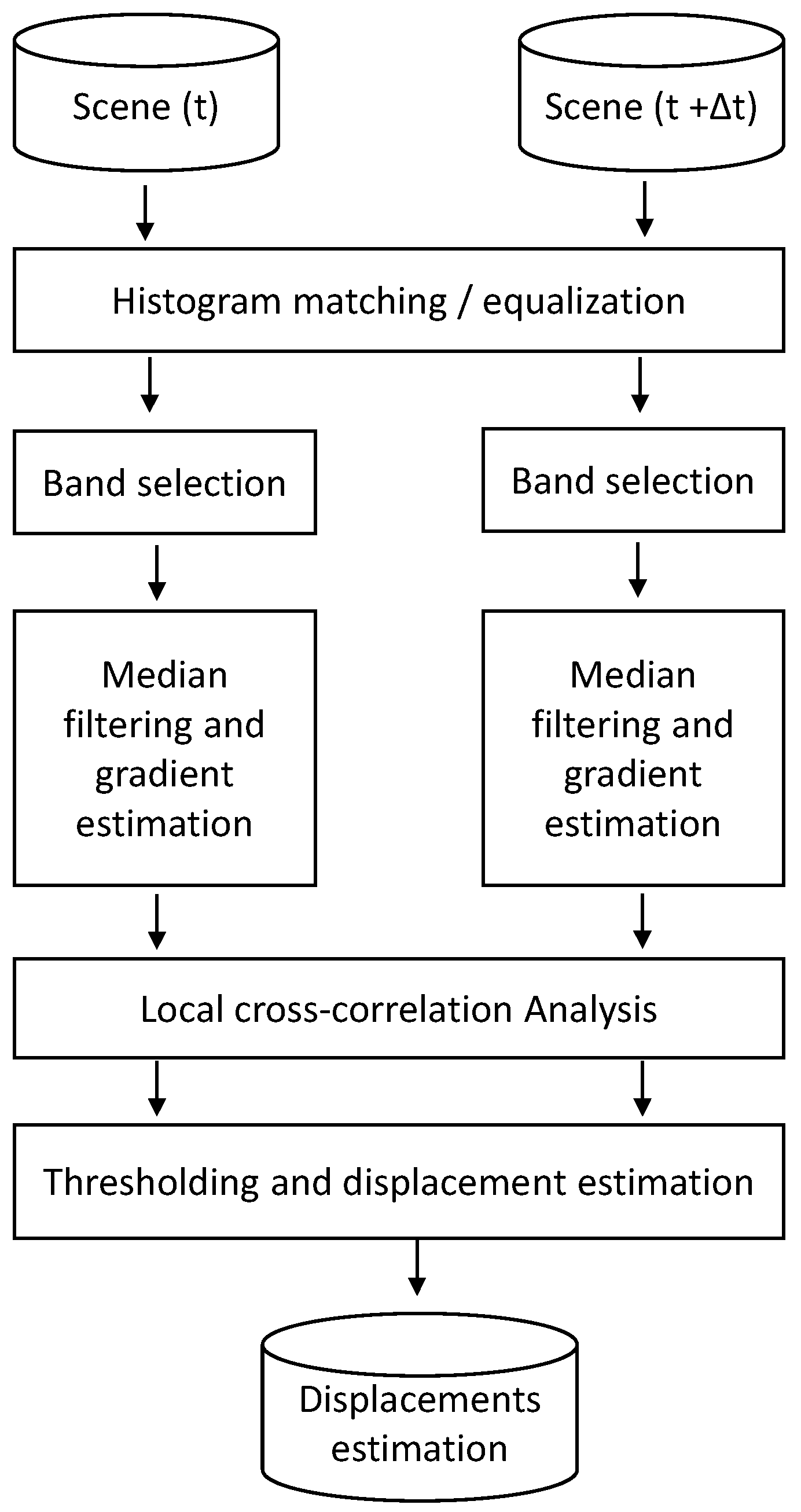
The analysis is carried out according to the diagram in Figure 15. Pre-processing has been implemented to improve the matching of the dunes between the two images. This was done by (i) adaptive histogram equalization to enhance sand contrast; (ii) matching the histogram of one image to the other; (iii) selection of the bands more sensible to dune; (iv) median filtering for noise removal while preserving edges; and (v) gradient evaluation to enhance morphology changes (edges of the dunes) while removing smooth luminance variations due to shading.
At this point, a local cross-correlation analysis was performed over windows of a size comparable to the dune (120 × 120 pixels). The last step involved the estimation of displacements, only for correlation values higher than 0.3.
The procedure was applied on dune D3 (Figure 12) and, as done for SAR offset tracking method, on a stable target. Figure 16a,b show displacements in azimuth direction registered for the dune D3 and the stable target, respectively. The shifts were computed for each band composing the RGB image.
Considering the stable target, no significant movement in correspondence of the highest correlation values is observed; this confirms the procedure goodness. Regarding the dune D3, the highest correlation values indicate a displacement of about 2.5 pixels (about 5 m) in the South direction over five years. Although a precise comparison is not possible due to the different time span considered, the optical offset tracking outcome seems qualitatively and quantitatively consistent with the corresponding SAR offset tracking estimation, which identifies displacements of few meters in the north-south direction.
4. Discussion
The main characteristics of the SAR-derived measures exploited for dune/sand instabilities investigation are reported in Table 2.
4.1. MSTC and TSI Indexes
Both the TSI and MSTC indexes allowed the detection of areas prone to instability consistent with the literature’s information. In the Egypt use case, TSI has also proven an excellent capability to identify the unstable dunes.
Since most of the tools needed for their calculation are available in SNAP software, the two indexes are not characterized by high computation complexity; moreover, unlike more complex SAR measurements such as the interferometric phase, their interpretation is relatively easy and does not require the intervention of SAR experts.
The minimal resolution of TSI and MSC indexes has been set to leave enough looks for a reliable coherence estimation. In that case, a total of L = 30 looks ensures a standard deviation of the coherence [36]:
that is about 0.12 by considering a coherence value γ equal to the threshold γT = 0.2 assumed to detect unstable targets.
Notice that, in principle, the uncertainty of the scene elevation, i.e., the DEM errors, could provide an undesired decorrelation, hindering the detection of stability. Sentinel-1 baselines are very small as by mission design. In the two datasets of Egypt and UAE, a standard deviation of the normal baselines of 37 m and 64 m, respectively, has been computed. In turn, by assuming mean incidence angle θ = 40°, mean range R0 = 880 km, wavelength the elevation of ambiguity [13] is:
we get = 428 m for Egypt and = 247 m for the UAE. A reasonable value for the SRTM vertical absolute accuracy is = 16 m [37], which would introduce a coherence [13]:
that would be = 0.97 for Egypt and = 0.79 for UAE. In both cases, the coherence would be well above the threshold of 0.2 that we fixed for totally decorrelated targets in the TSI.
Variations of soil moisture between two acquisitions could lead to coherence losses. This effect is mostly negligible for Sentinel-1, as discussed in [38]. Here, analysis has been carried out over several fields and extreme moisture variations due to heavy rain. In that extreme scenario, the coherence loss was about 0.08.
4.2. Offset Tracking
The offset tracking is capable of sensing the average displacements of huge sand accumulations, like dunes, with centimetric accuracy. As such, it can be used to detect and monitor instabilities. However, the offsets’ computation is cumbersome and time-consuming; furthermore, there are no modules in the SNAP package for that. The method’s robustness comes from the availability of many observables, N × (N − 1)/2, 2701 in our case, compared to the limited number of unknowns, N = 73 in our case. The final sensitivity has been shown comparable with the one achievable by very high-resolution optical imagery, which is hardly available over wide areas, and usually expensive.
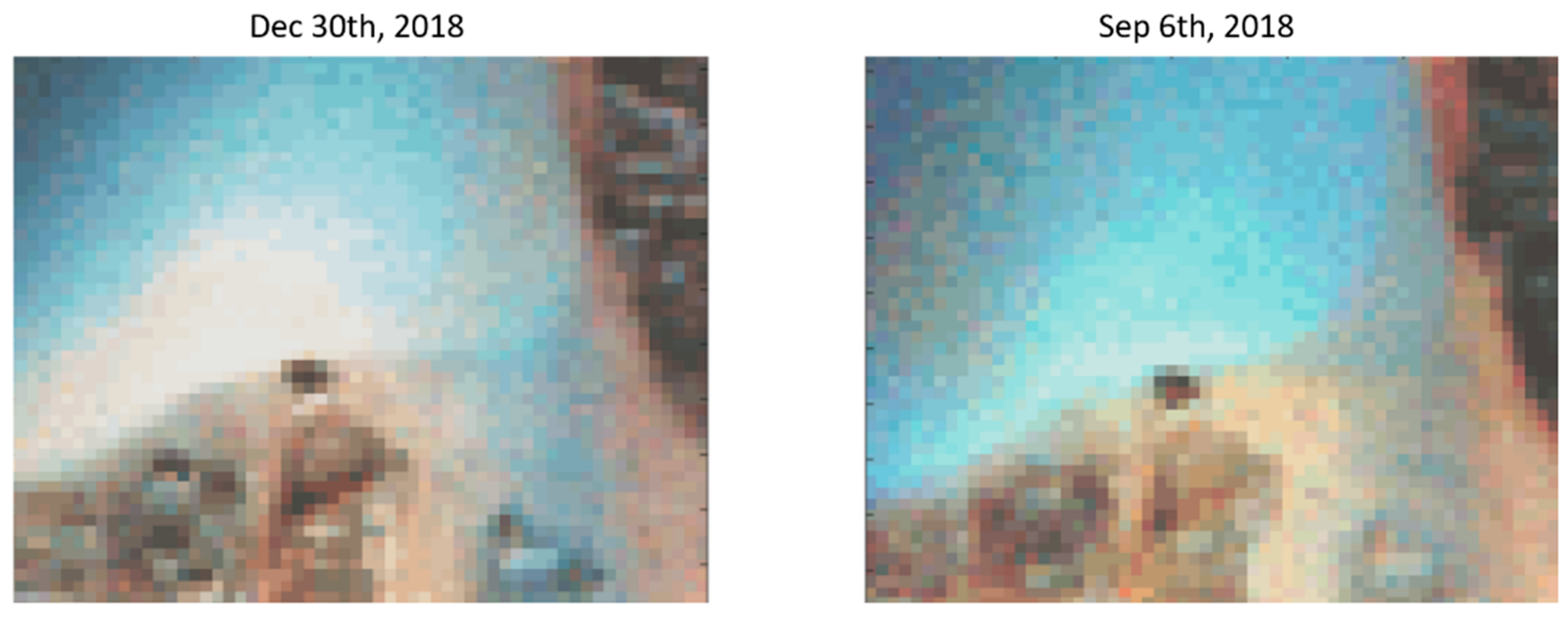
On the other hand, one could implement the same optical feature tracking shown in Figure 15 on Sentinel-2 images that are freely available with weekly revisit. An analysis carried out on a few of those images showed that the accuracy compares with the geometrical resolution, that is 10 m. This has been clarified in Figure 17, which represents a detail of the dune D3 in Figure 12 as observed by two Sentinel-2 images taken at different times. The changes in morphology and luminance prevent the sub-pixel accuracy, which microwaves can achieve.
5. Conclusions
The literature proves the suitability of SAR coherence to detect and evaluate sand accumulations motion in desert areas. Comprehensive information on the behavior over time of instabilities is critical information for planners who have to face the issues related to sand encroachment, especially in desert areas, which are characterized by high-frequency changes due to seasonal variations of wind regimes.
Here, SAR coherent methods have been successfully applied to a very long time series (2015–2018) of Sentinel-1 SAR images. The focus on Sentinel-1 imagery is very favorable, due to the systematic availability, since 2015, of free and open data in our area of interest, the repetition of the acquisition geometry, the wide swath imaged, and its sensitivity to backscatter from sand and dunes.
The work led to the generation of easy-to-interpret measures able to characterize instability over time. The most interesting is undoubtedly the Temporal Stability Index which has been conceived to fill a gap of the coherence temporal mean index (MSTC) by assessing the percentage of time a target remains stable. TSI is a more robust index than MSTC, as it is not affected by small changes like those due to topography. Moreover, the computation of TSI over huge areas, as wide as the Sentinel-1 scene (170 km × 250 km) is reasonably fast.
While TSI is suitable for detecting sand accumulation, quantitative tracking of dune walk can be provided by the SAR offset tracking. The technique has been shown robust and consistent with results from feature tracking based on very high-resolution optical imagery. However, its complexity limits the applicability to analysis over a small area of interest.
As a final remark, we note that the TSI is a novel index that deserves further studies and refinements to be applied for other landforms.
Author Contributions
Investigation, M.E.M. and A.M.-G.; Methodology, M.M.; Software, M.M., M.E.M. and A.M.-G.; Supervision, A.M.-G.; Validation, M.E.M. and M.M.; Writing—original draft, M.E.M.; Writing—review & editing, M.M. and A.M.-G. All authors have read and agreed to the published version of the manuscript.
Funding
This research received no external funding.
Institutional Review Board Statement
Not applicable.
Informed Consent Statement
Not applicable.
Data Availability Statement
The data presented in this study are available on request from the corresponding author.
Acknowledgments
The authors would like to thank Diego Frizzi and Stefano Martinati of Saipem S.p.A. for their active contribution to the research in the framework of the project “Satellite analysis of desert sand dunes migration”.
Conflicts of Interest
The authors declare no conflict of interest.
References
- Middleton, N.J.; Sternberg, T. Climate hazards in drylands: A review. Earth-Sci. Rev. 2013, 126, 48–57. [Google Scholar] [CrossRef]
- Hereher, M.E. Sand movement patterns in the Western Desert of Egypt: An environmental concern. Environ. Earth Sci. 2010, 59, 1119–1127. [Google Scholar] [CrossRef]
- Amin, A.; Abu Seif, E.-S. Environmental Hazards of Sand Dunes, South Jeddah, Saudi Arabia: An Assessment and Mitigation Geotechnical Study. Earth Syst. Environ. 2019, 3, 173–188. [Google Scholar] [CrossRef]
- Hugenholtz, C.H.; Levin, N.; Barchyn, T.E.; Baddock, M.C. Remote sensing and spatial analysis of aeolian sand dunes: A review and outlook. Earth-Sci. Rev. 2012, 111, 319–334. [Google Scholar] [CrossRef]
- Yao, Z.Y.; Wang, T.; Han, Z.W.; Zhang, W.M.; Zhao, A.G. Migration of sand dunes on the northern Alxa Plateau, Inner Mongolia, China. J. Arid Environ. 2007, 70, 80–93. [Google Scholar] [CrossRef]
- El-Magd, I.; Hassan, O.; Arafat, S. Quantification of Sand Dune Movements in the South Western Part of Egypt, Using Remotely Sensed Data and GIS. J. Geogr. Inf. Syst. 2013, 5, 498–508. [Google Scholar] [CrossRef]
- Baird, T.; Bristow, C.S.; Vermeesch, P. Measuring Sand Dune Migration Rates with COSI-Corr and Landsat: Opportunities and Challenges. Remote Sens. 2019, 11, 2423. [Google Scholar] [CrossRef] [Green Version]
- Hermas, E.; Leprince, S.; El-Magd, I.A. Retrieving sand dune movements using sub-pixel correlation of multi-temporal optical remote sensing imagery, northwest Sinai Peninsula, Egypt. Remote Sens. Environ. 2012, 121, 51–60. [Google Scholar] [CrossRef]
- Ding, C.; Zhang, L.; Liao, M.; Feng, G.; Dong, J.; Ao, M.; Yu, Y. Quantifying the spatio-temporal patterns of dune migration near Minqin Oasis in northwestern China with time series of Landsat-8 and Sentinel-2 observations. Remote Sens. Environ. 2020, 236, 111498. [Google Scholar] [CrossRef]
- Jian Guo, L.; Capes, R.; Haynes, M.; McMoore, J. ERS SAR Multi-Temporal Coherence Image as a Tool for Sand Desert Study (Dune Movement Sand Encroachment and Erosion). In Proceedings of the Twelfth International Conference and Workshop on Applied Geologic Remote Sensing, Denver, CO, USA, 17–19 November 1997. [Google Scholar]
- Rozenstein, O.; Siegal, Z.; Blumberg, D.G.; Adamowski, J. Investigating the backscatter contrast anomaly in synthetic aperture radar (SAR) imagery of the dunes along the Israel–Egypt border. Int. J. Appl. Earth Obs. Geoinf. 2016, 46, 13–21. [Google Scholar] [CrossRef]
- Moreira, A.; Prats-Iraola, P.; Younis, M.; Krieger, G.; Hajnsek, I.; Papathanassiou, K.P. A tutorial on synthetic aperture radar. IEEE Geosci. Remote Sens. Mag. 2013, 1, 6–43. [Google Scholar] [CrossRef] [Green Version]
- Ferretti, A.; Monti-Guarnieri, A.; Prati, C.; Rocca, F.; Massonnet, D. InSAR Principles: Guidelines for SAR Interferometry Processing and Interpretation; TM-19; ESA Publications: Noordwijk, The Netherlands, 2007. [Google Scholar]
- Bodart, C.; Ozer, A. The Use of Sar Interferometric Coherence Images to Study Sandy Desertification in Southeast Niger: Preliminary Results; European Space Agency, (Special Publication) ESA SP: Noordwijk, The Netherlands, 2007. [Google Scholar]
- Gaber, A.; Abdelkareem, M.; Abdelsadek, S.I.; Koch, M.; El-Baz, F. Using InSAR Coherence for Investigating the Interplay of Fluvial and Aeolian Features in Arid Lands: Implications for groundwater Potential in Egypt. Remote Sens. 2018, 10, 832. [Google Scholar] [CrossRef] [Green Version]
- Kwarteng, A.; Touzi, R.; Aljassar, H.K. Utilization of satellite SAR imagery for mapping sand dunes in Kuwait. In Proceedings of the IEEE Geoscience and Remote Sensing Symposium (IGARSS), Honolulu, HI, USA, 24–28 July 2000. [Google Scholar]
- Sentinel-1 SAR. Revisit and Coverage. Available online: https://sentinel.esa.int/web/sentinel/user-guides/sentinel-1-sar/revisit-and-coverage (accessed on 12 March 2021).
- Bechor, N.B.D.; Zebker, H.A. Measuring two-dimensional movements using a single InSAR pair. Geophys. Res. Lett. 2006, 33, L16311. [Google Scholar] [CrossRef] [Green Version]
- Strozzi, T.; Luckman, A.; Murray, T.; Wegmiiller, U.; Werner, C. Glacier motion estimation using SAR offset-tracking procedures. IEEE Trans. Geosci. Remote Sens. 2002, 40, 2384–2391. [Google Scholar] [CrossRef] [Green Version]
- Liu, F.H.; Zhao, Z.; Jezek, K.C. Synergistic Fusion of Interferometric and Speckle-Tracking Methods for Deriving Surface Velocity from Interferometric SAR Data. IEEE Geosci. Remote Sens. Lett. 2007, 4, 102–106. [Google Scholar] [CrossRef]
- Monti Guarnieri, A.; Tebaldini, S. Hybrid Cramér—Rao bounds for crustal displacement field estimators in SAR interferometry. IEEE Signal Process. Lett. 2007, 14, 1012–1015. [Google Scholar] [CrossRef]
- Prats-Iraola, P.; Lopez-Dekker, P.; De Zan, F.; Yagüe-Martínez, N.; Zonno, M.; Rodriguez-Cassola, M. Performance of 3-D Surface Deformation Estimation for Simultaneous Squinted SAR Acquisitions. IEEE Trans. Geosci. Remote Sens. 2018, 56, 2147–2158. [Google Scholar] [CrossRef] [Green Version]
- Alshehhi, A.; Abdelhamid, G. UAE Space Reconnaissance Center as a Valuable Imagery Resource for Monitoring the Environment; An Investigation on Sand Movement. In Proceedings of the 3rd Map ME Conference, Dubai, United Arab Emirates, 9–11 April 2007. [Google Scholar]
- El-Sayed, M. The nature and possible origin of mega-dunes in Liwa, Ar Rub’ Al Khali, UAE. Sediment. Geol. 2000, 134, 305–330. [Google Scholar] [CrossRef]
- Woods, W.W.; Imes, J.F. How wet is wet? Precipitation constraints on late quaternary climate in the southern Arabian Peninsula. J. Hydrol. 1995, 164, 263–268. [Google Scholar] [CrossRef]
- Lee, J.K.; Kim, J.C.; Kun, J.L.; Belorid, M.; Beeley, P.A.; Yun, J. Assessment of wind characteristics and atmospheric dispersion modeling of 137Cs on the Barakah NPP area in the UAE. Nucl. Eng. Technol. 2014, 46, 557–568. [Google Scholar] [CrossRef] [Green Version]
- Alhosani, N. Modeling and Mapping Sand Encroachment Risk as an Aid for Urban Planning in the United Arab Emirates (UAE). J. Geogr. Inf. Syst. 2018, 10, 699–717. [Google Scholar] [CrossRef] [Green Version]
- Bubenzer, O.; Embabi, N.S.; Ashour, M.M. Sand Seas and Dune Fields of Egypt. Geosciences 2020, 10, 101. [Google Scholar] [CrossRef] [Green Version]
- Gifford, A.W.; Warner, D.M.; El-Baz, F. Orbital observations of sand distribution in the Western Desert of Egypt. In Apollo-Soyuz Test Project Summary Science Report. Earth Observations and Photography, NASA SP-412; El-Baz, F., Warner, D.M., Eds.; NASA Scientific and Technical Information Branch: Washington, DC, USA, 1979; Volume 2, pp. 219–236. [Google Scholar]
- Hassoup, A. Sand dunes hazard assessment in El-Kharga Oasis, Egypt. In Proceedings of the 21st EGU General Assembly, Vienna, Austria, 7–12 April 2019. Geophysical Research Abstracts, 21, EGU2019-1714. [Google Scholar]
- Sansosti, E.; Berardino, P.; Manunta, M.; Serafino, F.; Fornaro, G. Geometrical SAR image registration. IEEE Trans. Geosci. Remote Sens. 2006, 44, 2861–2870. [Google Scholar] [CrossRef]
- De Zan, F.; Monti Guarnieri, A. TOPSAR: Terrain Observation by Progressive Scans. IEEE Trans. Geosci. Remote Sens. 2006, 44, 2352–2360. [Google Scholar] [CrossRef]
- Freeman, A. SAR calibration: An overview. IEEE Trans. Geosci. Remote Sens. 1992, 30, 1107–1121. [Google Scholar] [CrossRef]
- Gomba, G.; González, F.R.; De Zan, F. Ionospheric phase screen compensation for the Sentinel-1 TOPS and ALOS-2 ScanSAR modes. IEEE Trans. Geosci. Remote Sens. 2017, 55, 223–235. [Google Scholar] [CrossRef]
- Manzoni, M.; Monti-Guarnieri, A.V.; Realini, E.; Venuti, G. Joint Exploitation of SAR and GNSS for Atmospheric Phase Screens Retrieval Aimed at Numerical Weather Prediction Model Ingestion. Remote Sens. 2020, 12, 654. [Google Scholar] [CrossRef] [Green Version]
- Bamler, R.; Hartl, P. Synthetic aperture radar interferometry. Inverse Probl. 1998, 14, R1–R54. [Google Scholar] [CrossRef]
- Farr, T.G.; Rosen, P.A.; Caro, E.; Crippen, R.; Duren, R.; Hensley, S.; Kobrick, M.; Paller, M.; Rodriguez, E.; Roth, L.; et al. The shuttle radar topography mission. Rev. Geophys. 2007, 45, RG2004. [Google Scholar] [CrossRef] [Green Version]
- Palmisano, D.; Satalino, G.; Balenzano, A.; Bovenga, F.; Mattia, F.; Rinaldi, M.; Ruggieri, S.; Skriver, H.; Davidson, M.W.J.; Cartus, O.; et al. Sensitivity of Sentinel-1 Interferometric Coherence to Crop Structure and Soil Moisture. In Proceedings of the IEEE International Geoscience and Remote Sensing Symposium, Yokohama, Japan, 28 July–2 August 2019. [Google Scholar]
Figure 1.
Regions of interest (red boxes) and Sentinel-1 frames (blue boxes) selected for the United Arab Emirates (UAE) (a) and Egypt (b) use cases. Basemap © Google Copyright.
Figure 1.
Regions of interest (red boxes) and Sentinel-1 frames (blue boxes) selected for the United Arab Emirates (UAE) (a) and Egypt (b) use cases. Basemap © Google Copyright.

Figure 2.
Diagram representing the steps performed for computation of coherence-based indexes (Mean Short-Term Coherence abbreviated as MSTC and Temporal Stability Index, abbreviated as TSI) and offsets estimations from SAR images stacks. Blue boxes specify the tools available in the SNAP (Sentinel Application Platform) software.

Figure 3.
The geometric configuration of a multipass interferometric SAR system. The target P is imaged by radar passes at different acquisitions times from a slightly different look angle.
Figure 3.
The geometric configuration of a multipass interferometric SAR system. The target P is imaged by radar passes at different acquisitions times from a slightly different look angle.

Figure 4.
Mean Short-Term Coherence (MSTC) map. Low coherence values (red color) are shown in most of the region of interest. Basemap: © Google 2019 Copyright.
Figure 4.
Mean Short-Term Coherence (MSTC) map. Low coherence values (red color) are shown in most of the region of interest. Basemap: © Google 2019 Copyright.

Figure 5.
Temporal Stability Index (TSI) map. Very low values of TSI (red color) indicate areas partially or totally unstable. Basemap: © Google 2019 Copyright.
Figure 5.
Temporal Stability Index (TSI) map. Very low values of TSI (red color) indicate areas partially or totally unstable. Basemap: © Google 2019 Copyright.

Figure 6.
Temporal Stability Index (TSI) and high-resolution satellite optical image for the sub-areas highlighted in Figure 5. Basemap: © Google 2019 Copyright.
Figure 6.
Temporal Stability Index (TSI) and high-resolution satellite optical image for the sub-areas highlighted in Figure 5. Basemap: © Google 2019 Copyright.

Figure 7.
Variation over time of the total number of pixels characterized by a short-term coherence above threshold in the four identified sub-areas of Figure 5. Peaks of stability are detected in winter seasons in sub-areas a and c.
Figure 7.
Variation over time of the total number of pixels characterized by a short-term coherence above threshold in the four identified sub-areas of Figure 5. Peaks of stability are detected in winter seasons in sub-areas a and c.
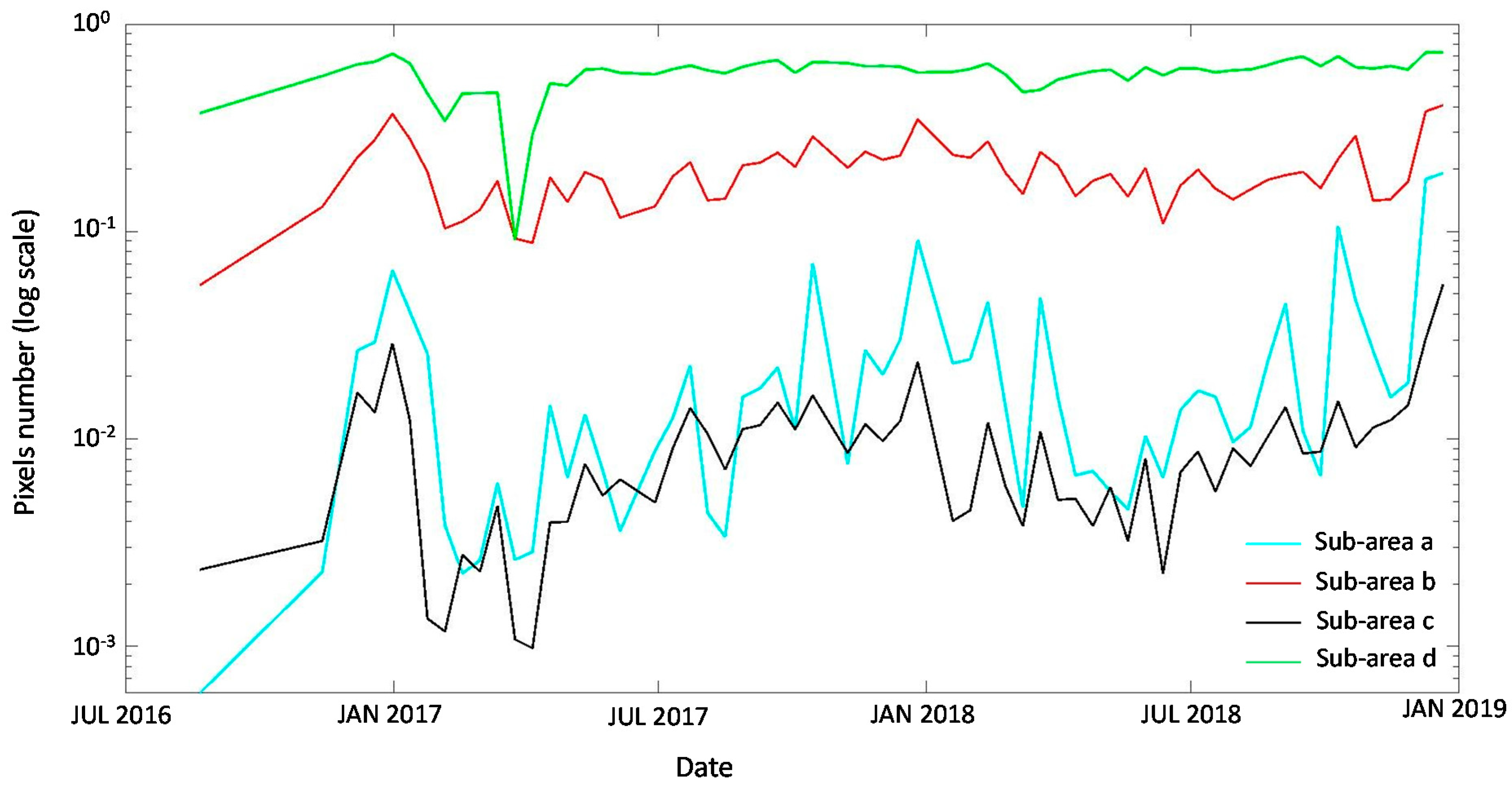
Figure 8.
Interferometric phase map computed between 3 November 2018 and 15 November 2018 and detail of the two sub-areas a and b. The pixels having an absolute value of coherence lower than the noise threshold are masked (black pixels). Basemap: © Google 2019 Copyright.
Figure 8.
Interferometric phase map computed between 3 November 2018 and 15 November 2018 and detail of the two sub-areas a and b. The pixels having an absolute value of coherence lower than the noise threshold are masked (black pixels). Basemap: © Google 2019 Copyright.

Figure 9.
Mean Short-Term Coherence (MSTC) (a) and Temporal Stability Index (TSI) (b) maps computed for the Egypt use case. Both the images highlight the high stability of the scene and very few low coherence areas. Basemap: © Google 2019 Copyright.
Figure 9.
Mean Short-Term Coherence (MSTC) (a) and Temporal Stability Index (TSI) (b) maps computed for the Egypt use case. Both the images highlight the high stability of the scene and very few low coherence areas. Basemap: © Google 2019 Copyright.

Figure 10.
Detail of sub-areas a and b outlined in Figure 9: optical high-resolution satellite images referred to the years 2013 and 2018, Mean Short-Term Coherence (MSTC) and Temporal Stability Index (TSI) maps. Images identify cultivated fields and sandy dune structures as very unstable areas.
Figure 10.
Detail of sub-areas a and b outlined in Figure 9: optical high-resolution satellite images referred to the years 2013 and 2018, Mean Short-Term Coherence (MSTC) and Temporal Stability Index (TSI) maps. Images identify cultivated fields and sandy dune structures as very unstable areas.

Figure 11.
Interferometric phase computed between 25 June 2018 and 7 July 2018. On the left, the whole area of interest is presented; on the right, a detail of dunes near El-Kharga shows displacements less than 6 cm in 12 days. Basemap: © Google 2019 Copyright.
Figure 11.
Interferometric phase computed between 25 June 2018 and 7 July 2018. On the left, the whole area of interest is presented; on the right, a detail of dunes near El-Kharga shows displacements less than 6 cm in 12 days. Basemap: © Google 2019 Copyright.

Figure 12.
Barchan dunes selected for SAR offset tracking application. Basemap: © Bing Satellite Copyright.
Figure 12.
Barchan dunes selected for SAR offset tracking application. Basemap: © Bing Satellite Copyright.

Figure 13.
Displacements registered for each considered dune (D1, D2, and D3) and the control point D4: shifts along the azimuth (nearly north-south) direction (top); shifts along the range direction (nearly east-west) (bottom).
Figure 13.
Displacements registered for each considered dune (D1, D2, and D3) and the control point D4: shifts along the azimuth (nearly north-south) direction (top); shifts along the range direction (nearly east-west) (bottom).

Figure 14.
Average 2D ground track of the dunes across the whole considered period estimated by SAR offset tracking (a); accuracy of measured displacements in range and azimuth for each dune (b).
Figure 14.
Average 2D ground track of the dunes across the whole considered period estimated by SAR offset tracking (a); accuracy of measured displacements in range and azimuth for each dune (b).
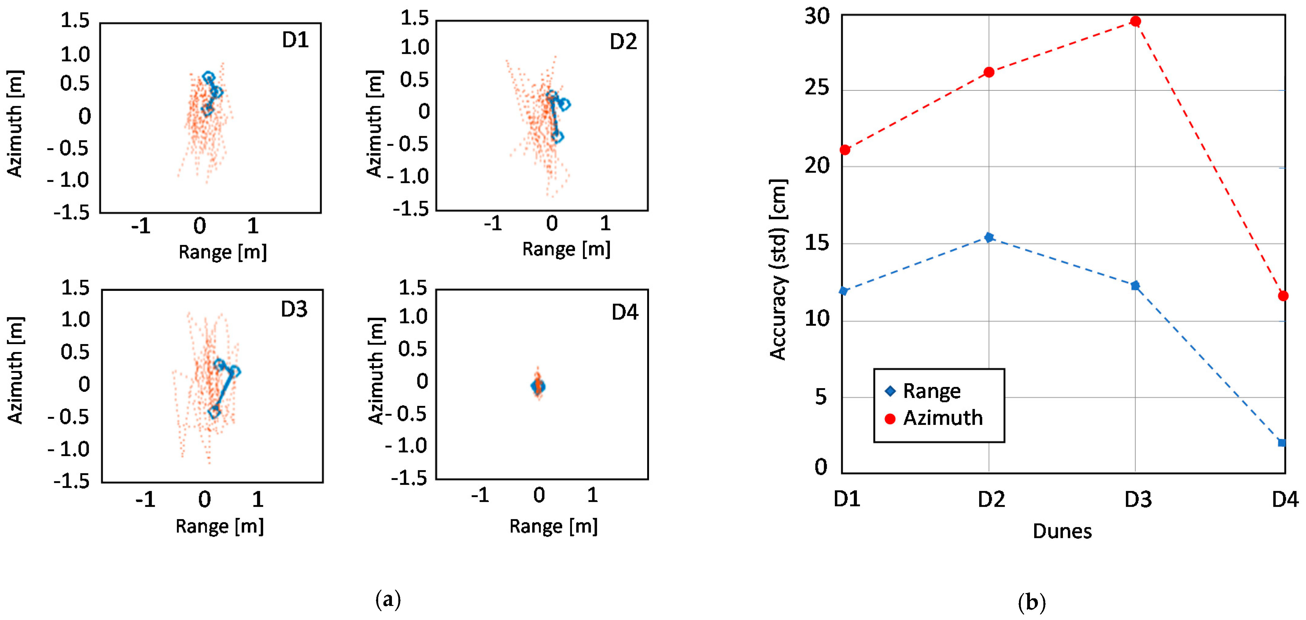
Figure 15.
Procedure of feature tracking from very high-resolution optical images.

Figure 16.
Feature tracking method: displacement in azimuth direction computed for dune D3 (a) and a stable target (b). The shifts corresponding to the highest correlation values are considered.
Figure 16.
Feature tracking method: displacement in azimuth direction computed for dune D3 (a) and a stable target (b). The shifts corresponding to the highest correlation values are considered.
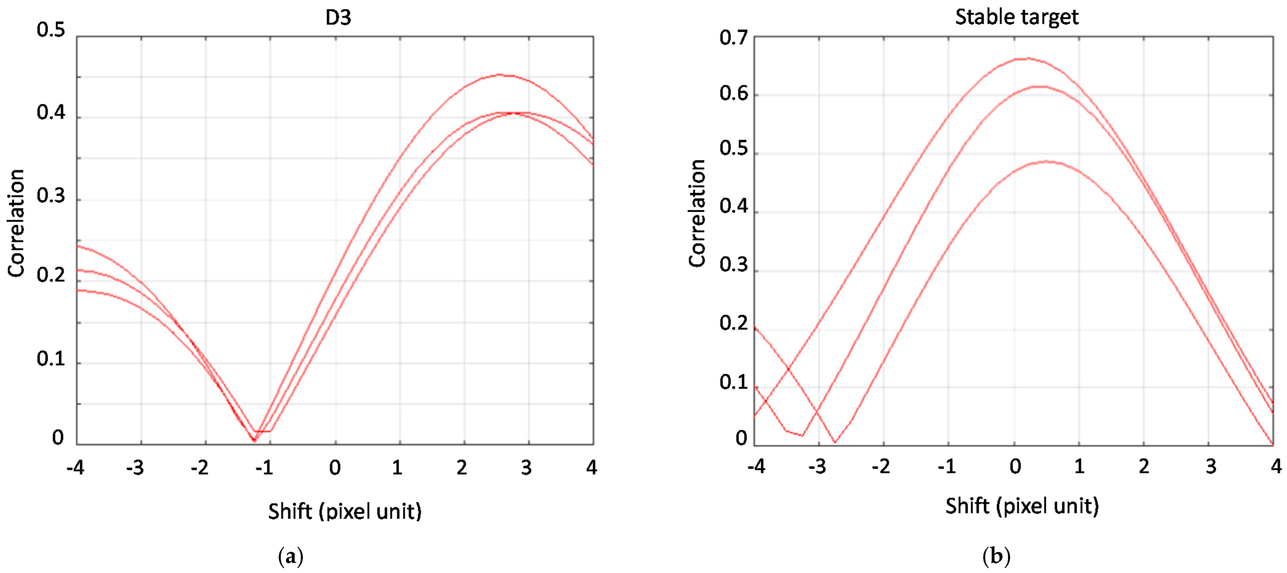
Figure 17.
Sentinel-2 optical images of dune D3 acquired at different times. Changes in dune luminance between the two scenes are evident.
Figure 17.
Sentinel-2 optical images of dune D3 acquired at different times. Changes in dune luminance between the two scenes are evident.


Table 1.
Information related to Synthetic Aperture Radar (SAR) imagery collected for the United Arab Emirates (UAE) and Egypt use cases.
Table 1.
Information related to Synthetic Aperture Radar (SAR) imagery collected for the United Arab Emirates (UAE) and Egypt use cases.
| UAE | Egypt | |
|---|---|---|
| Sensor | Sentinel-1A | Sentinel 1A/1B |
| Relative Orbit | 28 | 131 |
| Frame | 72 | 79 |
| Sub-swath | IW2 | IW2 |
| Pass | ascending | ascending |
| Number of images | 65 | 74 |
| First image acquisition date | 29 April 2015 | 6 May 2015 |
| Last image acquisition date | 21 December 2018 | 22 December 2018 |
| Revisiting time (years 2017–2018) | 12 days | 12 days |
| Scene center (lat, long) | 23.7069, 53.3529 | 25.284, 30.242 |
| Nominal Resolution (azimuth, range) | 20 m × 5 m | 20 m × 5 m |
Table 2.
Main characteristics of the SAR-derived measures.
| Measures | Sensitivity to Changes | Resolution | SNAP Native | Complexity |
|---|---|---|---|---|
| Temporal Stability Index (TSI) | Position (sub cm) | >45 m × 65 m | Partly | No |
| Mean Short-Term Coherence Index (MSTC) | Position (sub cm), topography | >45 m × 65 m | Partly | No |
| Dune offset estimation | Displacements > 10 cm | - | No | Yes |
Publisher’s Note: MDPI stays neutral with regard to jurisdictional claims in published maps and institutional affiliations. |
© 2021 by the authors. Licensee MDPI, Basel, Switzerland. This article is an open access article distributed under the terms and conditions of the Creative Commons Attribution (CC BY) license (https://creativecommons.org/licenses/by/4.0/).
Share and Cite
MDPI and ACS Style
Manzoni, M.; Molinari, M.E.; Monti-Guarnieri, A. Multitemporal InSAR Coherence Analysis and Methods for Sand Mitigation. Remote Sens. 2021, 13, 1362. https://0-doi-org.brum.beds.ac.uk/10.3390/rs13071362
AMA Style
Manzoni M, Molinari ME, Monti-Guarnieri A. Multitemporal InSAR Coherence Analysis and Methods for Sand Mitigation. Remote Sensing. 2021; 13(7):1362. https://0-doi-org.brum.beds.ac.uk/10.3390/rs13071362
Chicago/Turabian StyleManzoni, Marco, Monia Elisa Molinari, and Andrea Monti-Guarnieri. 2021. "Multitemporal InSAR Coherence Analysis and Methods for Sand Mitigation" Remote Sensing 13, no. 7: 1362. https://0-doi-org.brum.beds.ac.uk/10.3390/rs13071362
Note that from the first issue of 2016, this journal uses article numbers instead of page numbers. See further details here.