
Ghost Elimination via Multi-Component Collaboration for Unmanned Aerial Vehicle Remote Sensing Image Stitching


Key Laboratory of Computer Vision and System (Ministry of Education), Engineering Research Center of Learning-Based Intelligent System (Ministry of Education), School of Computer Science and Engineering, Tianjin University of Technology, Tianjing 300384, China
*
Author to whom correspondence should be addressed.
Remote Sens. 2021, 13(7), 1388; https://0-doi-org.brum.beds.ac.uk/10.3390/rs13071388
Submission received: 7 March 2021
/
Revised: 30 March 2021
/
Accepted: 2 April 2021
/
Published: 4 April 2021
(This article belongs to the Special Issue Semantic Segmentation of High-Resolution Images with Deep Learning)
Abstract
:Ghosts are a common phenomenon widely present in unmanned aerial vehicle (UAV) remote sensing image stitching that seriously affect the naturalness of stitching results. In order to effectively remove ghosts and produce visually natural stitching results, we propose a novel image stitching method that can identify and eliminate ghosts through multi-component collaboration without object distortion, segmentation or repetition. Specifically, our main contributions are as follows: first, we propose a ghost identification component to locate a potential ghost in the stitching area; and detect significantly moving objects in the two stitched images. In particular, due to the characteristics of UAV shooting, the objects in UAV remote sensing images are small and the image quality is poor. We propose a mesh-based image difference comparison method to identify ghosts; and use an object tracking algorithm to accurately correspond to each ghost pair. Second, we design an image information source selection strategy to generate the ghost replacement region, which can replace the located ghost and avoid object distortion, segmentation and repetition. Third, we find that the process of ghost elimination can produce natural mosaic images by eliminating the ghost caused by initial blending with selected image information source. We validate the proposed method on VIVID data set and compare our method with Homo, ELA, SPW and APAP using the peak signal to noise ratio (PSNR) evaluation indicator.
1. Introduction
Unmanned aerial vehicles (UAVs) are widely used in image collection because of their convenient operation and low cost. However, a UAV’s low flying altitude limits the field of view of the images. In order to obtain more comprehensive regional information, it is necessary to mosaic some images into a large range of images. UAV remote sensing image stitching is widely used in many real-world applications; for example, environment monitoring, disaster assessment and management [1]. An important feature of UAV remote sensing image acquisition is scanning capture, where there are moving objects in the image scene. In UAV remote sensing images, creating a mosaic is quite challenging; ghosts usually exist in the mosaic results, and are difficult to be remove.
The process of image stitching comprises two stages: image registration and image blending. Image registration is performed to calculate the relative transformation of two stitched images, so that the stitched image can be transformed into a unified coordinate system. Image blending is done to form a panoramic image with a large field of view using overlapped regions. Ghosts usually occur in the process of image blending; a moving object may appear in an adjacent stitched image. In this case, most of the image mosaic methods inevitably produce ghosts; because the blending image region is inconsistent. The ghost phenomenon not only affects the naturalness of stitching results, but also affects the application of stitching results. In this work, our main goal is to mosaic UAV remote sensing images and eliminate ghosts to obtain natural stitching results and achieve a comprehensive image of the scene.
The existing image stitching methods mainly solve the problem of improving registration accuracy by designing a good transformation function. For UAV remote sensing image mosaics, additional information is usually needed, such as camera calibration parameters, or position and rotation data obtained from the GPU/IMU, ground control points or a reference map, to achieve accurate mosaic results. However, these additional parameters do not focus on the ghost phenomenon caused by moving objects, and the ghosts cannot be eliminated by a transform function. The seam-driven image stitching method can alleviate these problems to a certain extent. However, there are still limitations in dealing with ghosts due to the following reasons: first, when there is a moving object in the stitched image, the seam may cut or copy the object; secondly, the seam-driven method selects one of multiple seams as the final seam, and if there are fast moving objects in the stitched images, the process of seam finding method becomes challenging.
In short, the seam-driven method cannot deal with all the challenges of eliminating ghosts, and ghost elimination is an urgent problem. In particular, when shooting images that are generally used for stitching, they may be at the same position or have a small rotation. However, when the UAV’s bird’s-eye view camera captures images, important factors are not only translation and rotation, but also the distance between the camera and the object, and the level of shaking, resulting in small objects in UAV remote sensing images and poor image quality, which in turn increases the difficulty of image stitching and the removal of ghosts.
In this paper, we propose a multi-component collaboration method to stitch UAV remote sensing images while eliminating ghosts without a seam finding process. Intuitively, we first identify the ghost region, then select the image information source, and finally replace the ghost region with the selected image information source.
In summary, our main contributions are as follows:
- We propose a method based on multi-component collaboration to stitch UAV remote sensing images, which can achieve a natural stitching performance;
- We design a ghost identification component that can identify the ghost area of small objects in UAV remote sensing images and accurately identify multiple ghosts;
- We realize a UAV remote sensing image stitching method without requiring additional information and seam optimization that can produce natural stitched images by using selected image sources to eliminate ghosts in the initial blending result.
2. Related Work
This paper focuses on eliminating ghosts in UAV remote sensing image stitching. Therefore, in this section, we introduce the current mainstream work from two aspects: UAV remote sensing image stitching and ghost elimination.
2.1. UAV Remote Sensing Image Stitching
The existing image mosaic methods focus on two aspects: registration accuracy and distortion reduction. Registration accuracy is an important research problem in image stitching. After more than 10 years of research, some progress has been made in this area. The key to improving registration accuracy is to design a good transform function. The initial image stitching calculates a global transform function to register two stitched images. This method is called homography, and is used as the baseline of the stitching method. In 2007, AutoStitch [2] was proposed to stitch multiple images, in the image registration stage, a global transform is also used to register images. These methods are good for images with only translation or small rotation; but are insufficient for images with large rotation; that is, they cannot solve the parallax problem. To address parallax, multiple transformations are used to register images rather than a single global homography. In 2011, Gao et al. [3] divided a stitched image into two planes, and then calculated two homography matrices to register the images. Because some images may not be clearly divided into two planes, this method is not applicable to all images. Lin et al. [4] used multiple affine transformation matrices to improve the accuracy of image registration. In 2014, APAP [5] was proposed, which is a classic image stitching method. It divides an image into several grids of fixed size and computes multiple homography matrices to register the image. This method achieves good results for images with large parallax. Liu et al. [6] proposed a shape-optimizing and illumination-smoothing image stitching method and an automatic grid generation strategy. Lee et al. [7] proposed a new concept of the warping residual, which is based on a warping residual to stitch large parallax images. Zheng et al. [8] used the normal vector’s orientations of local regions and the projection errors of aligned images to segment an image; to improve the image registration accuracy. Li et al. [9] proposed an image stitching method based on robust elastic warping, which can stitch large parallax images and achieve accurate registration. In addition, for low texture image stitching, Xiang et al. [10] used the line-guided local warping method to achieve accurate registration. For large parallax video stitching, Lee and Sim [11] used the epipolar geometry method to stitch.
Through various registration methods, the overlapping areas of two images can be well aligned, and the non-overlapping areas usually have serious distortions. Chang et al. [12] proposed (the SPHP) algorithm, which corrects the shape of the stitched image, and reduces the projection distortion. Lin et al. [13] proposed a homography linearization method, which is also a shape correction problem; the natural appearance of the stitching results is improved with this method by a level compared with SPHP. Chen et al. [14] proposed the global similarity prior (GSP) to obtain natural stitching results, which uses line alignment constraints to set constraint terms. Liao et al. [15] used two single-perspective warps to register images to produce natural stitching results. Li et al. [16] proposed a novel quasi-homography to solve the line blending problem between the homography transformation and the similarity transformation by linearly scaling the horizontal component of the homography, to create a more natural panorama.
UAV image mosaic usually needs additional information, such as camera calibration parameters, and position and rotation data from the GPS/IMU, ground control points or a reference map, to achieve accurate mosaic results [17,18,19,20,21,22,23,24]. When the GPS/IMU data are not sufficiently accurate, the stitching may be affected. Xue et al. [24] proposed a novel image mosaic method without the requirements of camera calibration parameters, camera poses, or any 3D reconstruction procedure. This method can obtain visually satisfactory mosaic results automatically using only the raw 2D imagery captured from a UAV. Liu et al. [25] considered mosaic for low overlap UAV aerial images and found that the commonly used methods and software were not suitable for this type of data. Then, a novel adjustment model for mosaic low-overlap sweeping images was proposed. Cai et al. [26] proposed a robust transform estimator based on residual analysis and its application to UAV aerial images. Estimating the transformation between two images from the same scene is a fundamental step for image registration, image stitching and 3D reconstruction.
2.2. Ghost Elimination
At present, there are few studies on ghost elimination. Kakli et al. [27] noted that the presence of moving objects in a stitched image would cause blurring or ghosts, and proposed the minimization of parallax artifacts in video stitching for moving foregrounds. Davis et al. [28] proposed a stitching method for scenes with moving objects: first, the stitched image is divided into disjointed regions, and the pixels of each region are sampled from a single source image; then, the intensity difference images of the two images are calculated and the Dijkstra algorithm is used to find the seam. The work in [29] used the seam-driven method to eliminate ghosts. The purpose of that study was to remove pedestrians from Google Street View images and obtain pedestrian positions by using the pedestrian detection method.
These methods all use the seam-driven method to eliminate ghosts. The seam-driven method can avoid and eliminate ghosts to a certain extent, but it cannot deal with all the challenges of eliminating ghosts. For example, when a seam passes through a moving object, the moving object is cut. When a seam is placed between two moving objects, the moving objects are copied. Therefore, it is difficult to eliminate the ghosts by using the seam-driven method. Our method can effectively deal with ghosts produced by moving objects in UAV remote sensing mosaic without using the seam-driven method.
3. Methodology
3.1. Overview
An image mosaic is used to stitch two images with overlapping areas to form a panorama with a large field of view. Given two image and , is the reference image. Generally, the image stitching process is split into the following steps: first, we perform image registration and calculate the homography matrix as relative to . Second, we transform through the homography matrix with . Finally, we perform an image blend between and .
In real-world applications, two images are usually taken from a camera twice and rotated in the same scene with different angles or small camera positions, or appropriate key frames are selected from a video. Since the two images are not taken at the same time, the objects move through the scene, resulting in ghosts in the stitching result and leading to a major challenge for the image stitching problem. There are two challenges for UAV remote sensing image stitching:
- (1)
- Due to the large shooting distance between the UAV and the object, the object in the UAV remote sensing image is very small;
- (2)
- The image quality of UAV remote sensing images is poor due to the shaking of UAV shooting equipment.
In order to deal with the above challenges, we focus on the image blending process and propose a multi-component cooperation method for ghost identification and elimination, which is used for UAV remote sensing image mosaic. Intuitively, we first identify potential ghost regions in the blending region, and then explore how to eliminate them using appropriate image information sources, which are selected from two input images in the same ghost environment. Finally, the image information source is used to replace the ghost area to form a natural mosaic result. The above process has the following difficulties:
- (1)
- It is difficult to identify the ghost region because of the variety of motion patterns and the different types of ghost. In order to deal with this problem, we propose the ghost identification component in Section 3.2 for effective ghost identification;
- (2)
- It is also a challenge to choose the image information source for the ghost’s replacement. We should ensure that the objects in the final result are not copied or cut. To deal with this challenge, we propose an image information source selection component to select the appropriate image information source. In Section 3.3, we design three rules to avoid object distortion, cutting and repetition;
- (3)
- Using the identified ghost region and image information source, we naively perform region substitution, which easily causes a serious seam in the ghost region. In order to avoid this problem, we propose a ghost elimination component in Section 3.4 that can effectively eliminate ghosts and enhance the naturalness of stitching results.
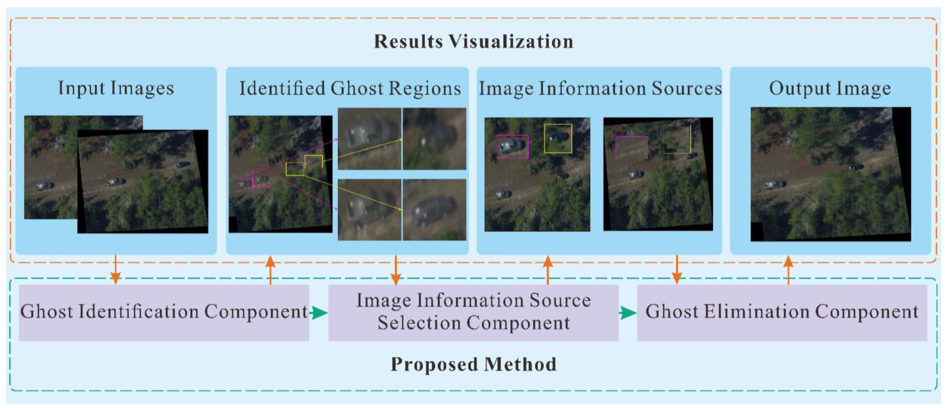
The proposed multi-component cooperative ghost identification and elimination method is divided into three components: ghost identification, image information source selection and ghost elimination. The three components cooperate to complete the ghost identification and elimination in UAV remote sensing image mosaic to produce natural mosaic results. We show the collaboration flow of the three components in Figure 1.
3.2. Ghost Identification Component
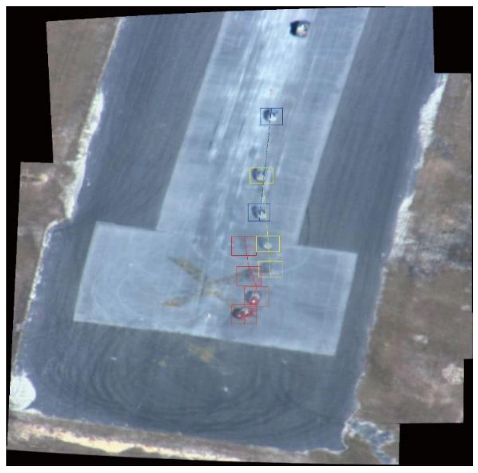
Different ghosts are generated according to different motion trajectories of objects. As shown in Figure 2, the boxes with the same color represent the same object, correspondingly, the boxes with different colors represent different objects, and the dotted line describes the moving track of the object.
The performance of ghosts is diverse in image mosaic. Because the performance and motion modes of objects are different between cases, it is difficult to identify the corresponding ghosts accurately. Intuitively, only objects in the overlapping region may produce ghosts, which lead to the inclusion of different or non-aligned objects in the overlapping area of two images as shown in Figure 3. The region marked by the red box is the overlapping region. We observe the object marked by the green box. In Figure 3a, the object is in the overlapping region; in Figure 3b, the object is in the non-overlapping region. In the final stitching result, the object in the overlapping region is shown as a ghost, due to the corresponding region not being an object in Figure 3b, while the object in the non-overlapping region is still a real object.
Based on the above analysis, because there are non-aligned objects in the overlapping region, ghosts are produced. In order to correctly identify the ghost region, we first find the overlapping region of the stitched images, and then identify the non-aligned object regions (ghost regions) in the overlapping region. Specifically, we identify ghosts with the following steps:
- (1)
- The overlapping region of stitched images is calculated according to the homography transformation matrix, i.e., and corresponding to the overlapping regions of and respectively;
- (2)
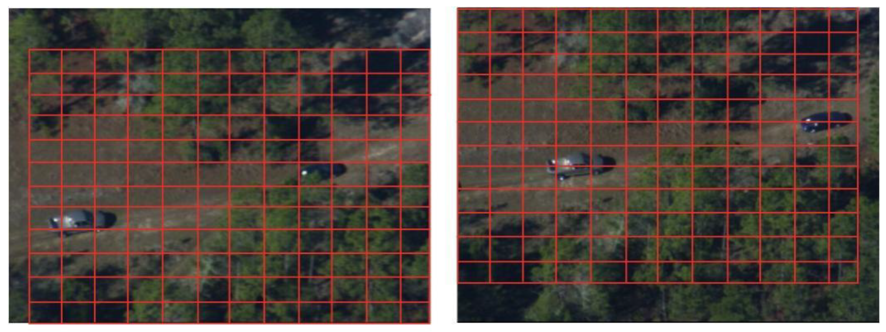
- Because the object in the UAV remote sensing image is too small and the image quality is poor, it is difficult to obtain the object information from the scene by using the object detection method directly. Therefore, we propose a mesh-based ghost identification method. Meshing is performed on the overlapping regions of two images (i.e., and ). The divided grids are denoted as and where and are the meshes in and , respectively, as shown in Figure 4;
- (3)
- Calculating the average pixel difference of the corresponding mesh in and :where is the difference between the mesh in and . Intuitively, if is large (i.e., larger than a specified threshold ), the blended regions are not the same and the blended result tends to be a ghost in the final result.
In a real UAV remote sensing image, there are usually multiple objects, so it is challenging to distinguish each ghost:
- (4)
- Utilizing a state-of-the-art object tracker, i.e., KCF [30], to perform object tracking to accurately correspond to each ghost object.
3.3. Image Information Source Selection Component
In order to obtain a natural stitching result, we choose the appropriate image information source to eliminate ghosts. When we choose the image information source, we should avoid selecting distorted objects as much as possible. Because the objects in the warped image will have different degrees of distortion, we should choose the objects in the reference image as the image information source as far as possible. When there are two non-aligned objects in the overlapping region, we choose one object region and the corresponding region of another object as the image information source. When there is an object on the boundary of the overlapping region, we must select the object as the image information source.
In order to deal with the above problems, we designed three rules for the selection of image information sources:
- Shape-stabilized rule: This rule was created to make the final stitching result more natural and keep the object as natural as possible. When there are objects in both images, we usually take the left image as the reference image while the right image undergoes transformation, and then the two images are blended. Correspondingly, the objects in the right image also have deformation. Therefore, we should choose the objects in the reference image as the image information source;
- Completeness rule: This rule mainly eradicates the ghosts at the edge of the overlapping region. When a complete ghost object and ghost at the edge of the overlapping region exist simultaneously in the final stitching result, we should select the object at the edge of the overlapping region as the image information source to ensure the completeness of the object;
- Uniqueness rule: This rule is used to ensure that the same object appears only once in the final stitching result. It can avoid the repetition of objects; and also ensure that the scene information is complete.
3.4. Ghost Elimination Component
This section focuses on the elimination of ghosts. The basic principle of eliminating ghosts is to try to make the moving objects in the stitched image come from an image. Specifically, we first obtain an initialized blended image by naively blending and , where we average the overlap regions of the two images as the blending region. Then, we combine the initialized blending result with the image information source selected from or ; we aim to generate a blended image by a seamless clone [31]:
where, is the selected image information source.
Seamless clone is a method based on the Poisson equation for seamless image blending. In the process of image blending, it is applied in the gradient domain of the image. Using a color gradient instead of the color intensity can produce a more realistic effect. Our seamless blending is guided by the gradient field in the source image block, and the difference between the target scene and the source image on the blended boundary is smoothly diffused into the blended image block; in this way, the blended image block can be seamlessly blended into the target scene, and its hue color and illumination can be consistent with the target scene. Specially, for the initialized blended image and the image information source , we want to interpolate into ; for this, we only need to use the gradient of as the guide gradient and solve the Poisson equation.
3.5. Implementation Details
In this section, we first show the entire flow of our proposed algorithm, as shown in Figure 5, and then we elaborate on some details for implementing our method. We used the SIFT [32] feature point detection algorithm of VLFeat [33] to get the feature points of the image, and used RANSAC [34] to remove mismatches and calculate the transformation matrix. In the ghost identification component, the meshes were divided into pixels in overlapping regions of the two images.
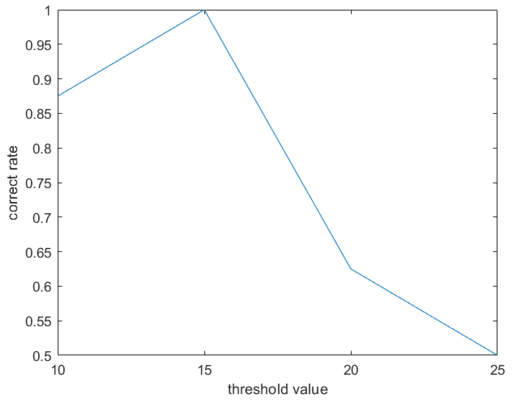
For the average pixel difference of the corresponding mesh, we set the threshold to be 15 to obtain a mesh with a large difference. The threshold was used to determine whether the region was the ghost region. The larger the threshold, the greater the difference between the two regions (the region tends to be a ghost). The threshold was determined by experiments. The experimental results are shown in Figure 6. We tested with the threshold set between 10 and 25, and the step size as 5. When was 10, the correct rate of identifying ghosts was 87.5%; when was 15, the correct rate of identifying ghosts was 100%; when was 20, the correct rate of identifying ghosts was 62.5%; when was 25, the correct rate of identifying ghosts was 50%. Therefore, in this paper, was set as 15.
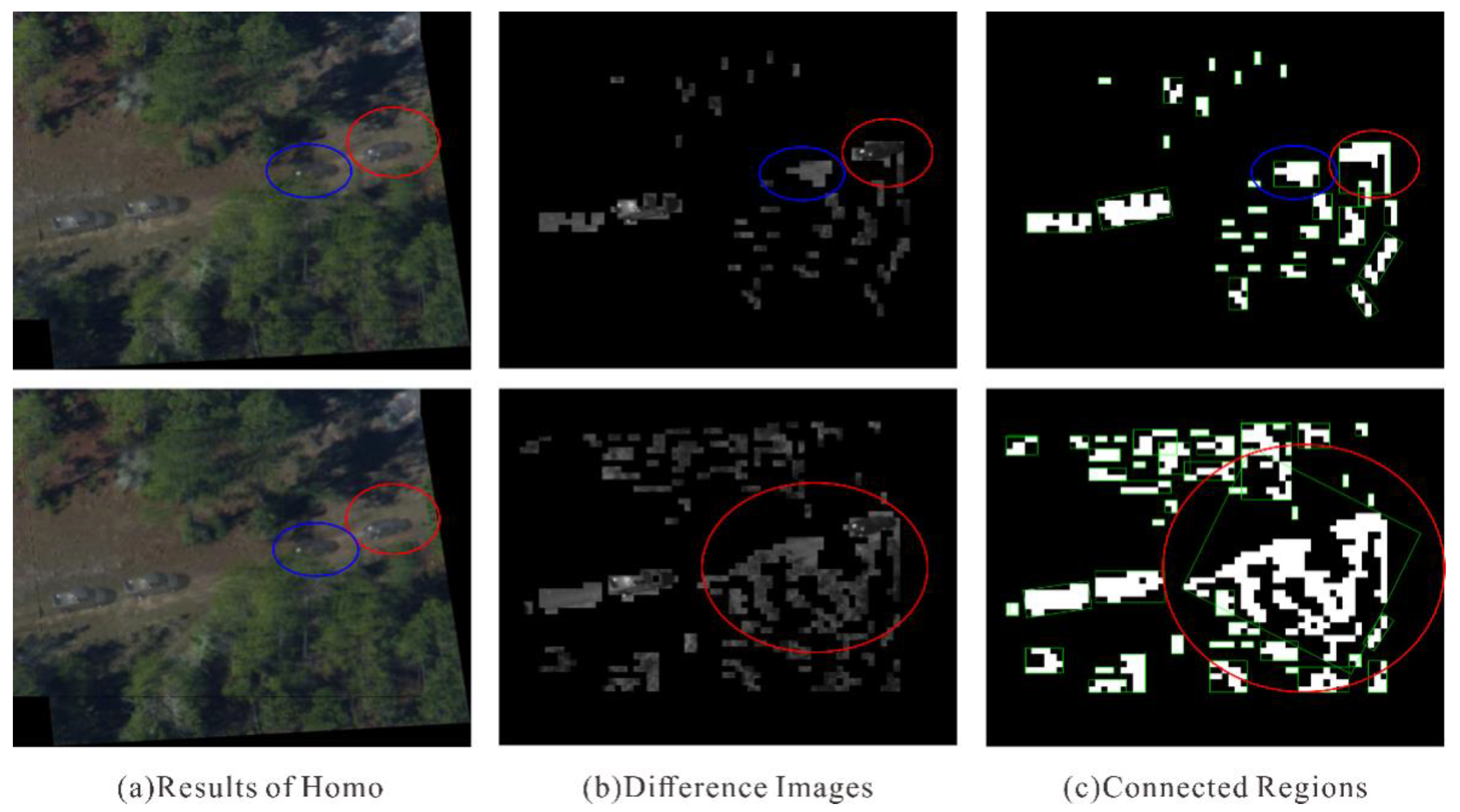
If the value of is too small, the object cannot be distinguished, as shown in Figure 7. In Figure 7a, two ghost regions are marked with red and blue; the first line of Figure 7b,c is the result with a threshold value of 15, which allowed the two regions to be correctly identified, while the second line is the result of a threshold value of 10, which did not allow the two regions to be distinguished. If the value of is too large, the ghost region cannot be identified, as shown in Figure 8. Figure 8b shows the result for a threshold value of 15, with which three ghost regions could be identified. Figure 8c shows the result for a threshold value of 20, where only two regions could be identified.
In the case of an inappropriate threshold, the ghost region cannot be identified, and our technology reverts to the standard stitching.
4. Experimental Evaluation
In this section, we show the results of our proposed method and compare with the following state-of-the-art methods to demonstrate its effectiveness: Homography (Homo), APAP [5], ELA [11] and SPW [15]. Homography is conducted to calculate a global transform function to register two stitched images. APAP divides the image into several grids of fixed size and computes multiple homography matrices to register the image. This method achieves good results for images with large parallax. ELA is an image stitching method based on robust elastic warping, which can stitch large parallax images and achieve accurate registration. SPW uses two single-perspective warps to register images to produce natural stitching results. In particular, the SPW method has two blending parameters: average and linear. We obtained the stitching results using the source codes provided by the authors. We also verified the effectiveness of the proposed mesh-based ghost identification method. All of our experiments were conducted on the VIVID data set. We will evaluate the proposed method in terms of processing time, quantitative comparison, qualitative comparison and user study.
4.1. Effectiveness of Mesh-Based Ghost Identification Method
In the ghost identification process, in order to obtain information about objects in the scene, if we intuitively use an object detection method to obtain object information, there may be some limitations, such as poor image quality and small objects. Therefore, we propose a mesh-based ghost identification method. In order to verify the effectiveness of our proposed mesh-based ghost identification method, we conducted a comparative experiment with the object detection method. Here, we took the SSD [35] object detection method as an example. The comparative results are shown in Table 1.
In Table 1, “Proposed” stands for the proposed method, “T” indicates that the ghost object could be identified successfully, “F” indicates that the object detection failed and “E” indicates that the object detection was incorrect.
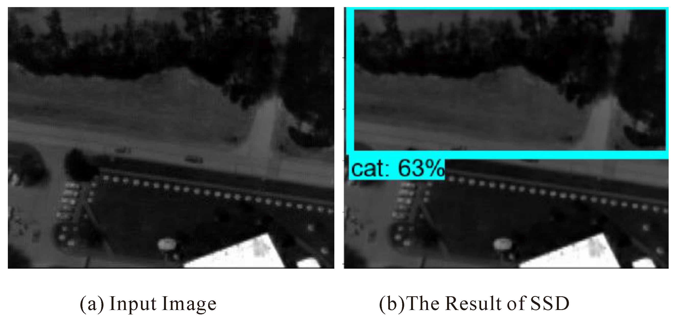
It can be seen from Table 1 that the object detection method does have limitations in our experimental data. However, the mesh-based ghost identification method could correctly identify the ghost objects. Figure 9 shows an error case of object detection. Figure 9a shows the input images, and Figure 9b shows the detected result of SSD. “cat:63%” means that the probability that the detected object was a cat was 63%. The region marked with a blue rectangle is the object detected by SSD. Obviously, this region was not a single object, which proves that the detection result of SSD was incorrect.
The ghost identification method based on object detection is limited by the object; for example, it only works on the objects in the training set, the content in the background of the mosaic image cannot be detected, and a registration ghost may be produced due to the inaccurate registration caused by large parallax. However, the proposed method can successfully eliminate the registration ghosts in the background, as shown in Figure 10.
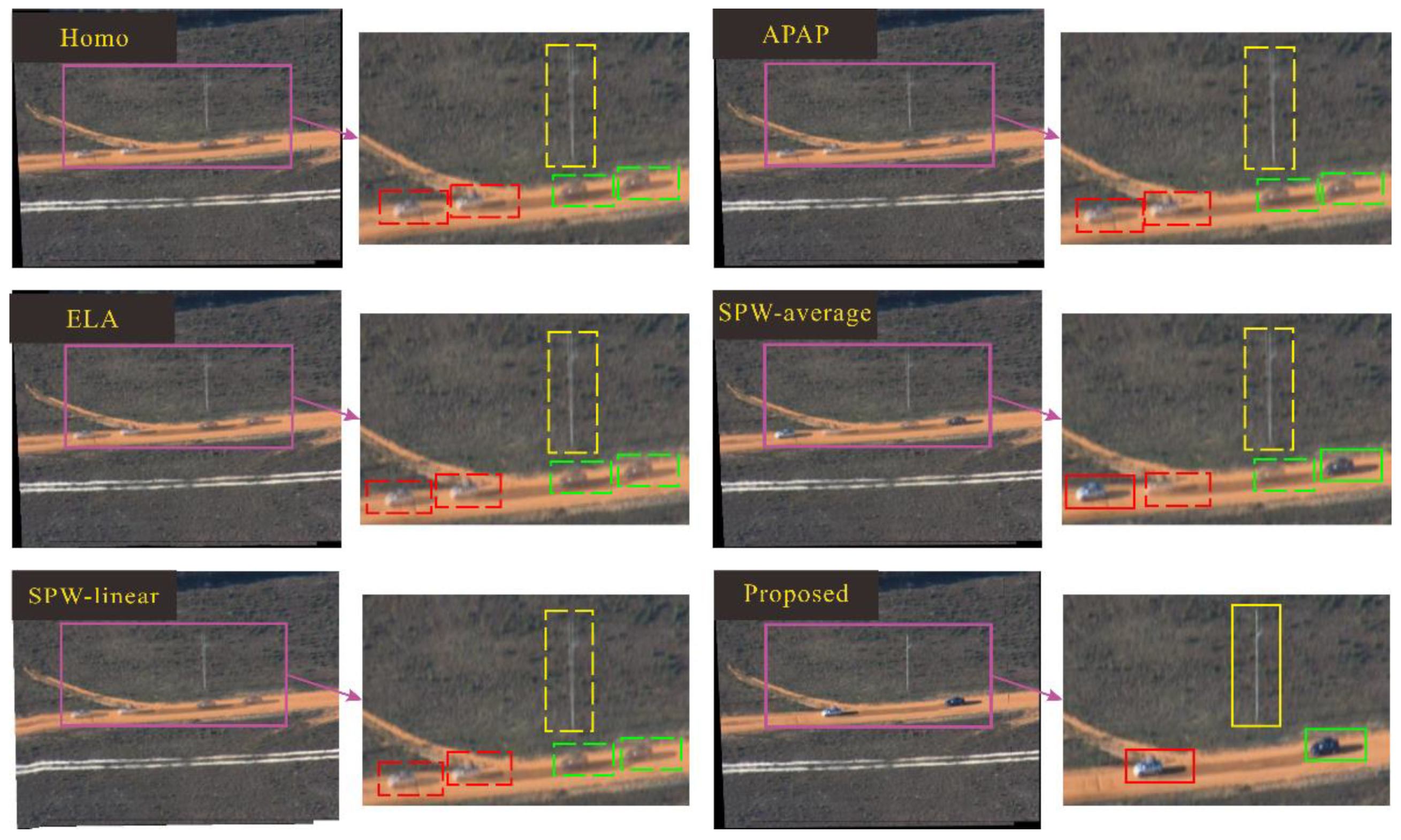
In Figure 10, we compare the Homo, APAP, ELA and SPW methods. The red box and the green box represent two different cars. It can be seen that only our results guarantee the uniqueness of each car. In the final result, each car only appears once, and it is a real object rather than ghost. The yellow box is the ghost produced by the content in the background, which could not be achieved by the ghost identification method based on object detection. Moreover, the ghost identification method based on a mesh could identify the ghost, and the proposed method could correct the ghost very well.
4.2. Processing Time Comparison
We compared the processing times of Homo, APAP, ELA, SPW and the proposed method, and the results are shown in Table 2. In the comparison of the five methods, on the whole, APAP had the longest processing time. There were two groups of data stitching failures in the SPW method, and the processing time of SPW was also relatively long. Although the processing time of the Homo method and ELA were lower than that of the proposed method, Homo and ELA did not pay attention to moving objects, and there were ghosts in the stitching results. The processing time of the proposed method was lower than that of APAP and SPW.
4.3. Quantitative Comparison
We compared the proposed method with Homo, APAP, ELA and SPW by the Peak Signal to Noise Ratio (PSNR). Since there were moving objects in the two stitched images, comparison involved calculating the PSNR value of the overlapping region of the stitching result, the overlapping region of and the overlapping region of , and then calculating the average value of the two values as the final result. The calculation method for PSNR is shown in Equation (3). The comparison results are shown in Table 3. The PSNR value of the proposed method outperforms the other methods:
where is the overlapping region of the final stitching result, is the overlapping region of the stitched image (i.e., , ), the size of the overlapping region is and the pixel value is represented by B-bit binary; then, .
4.4. Qualitative Comparison
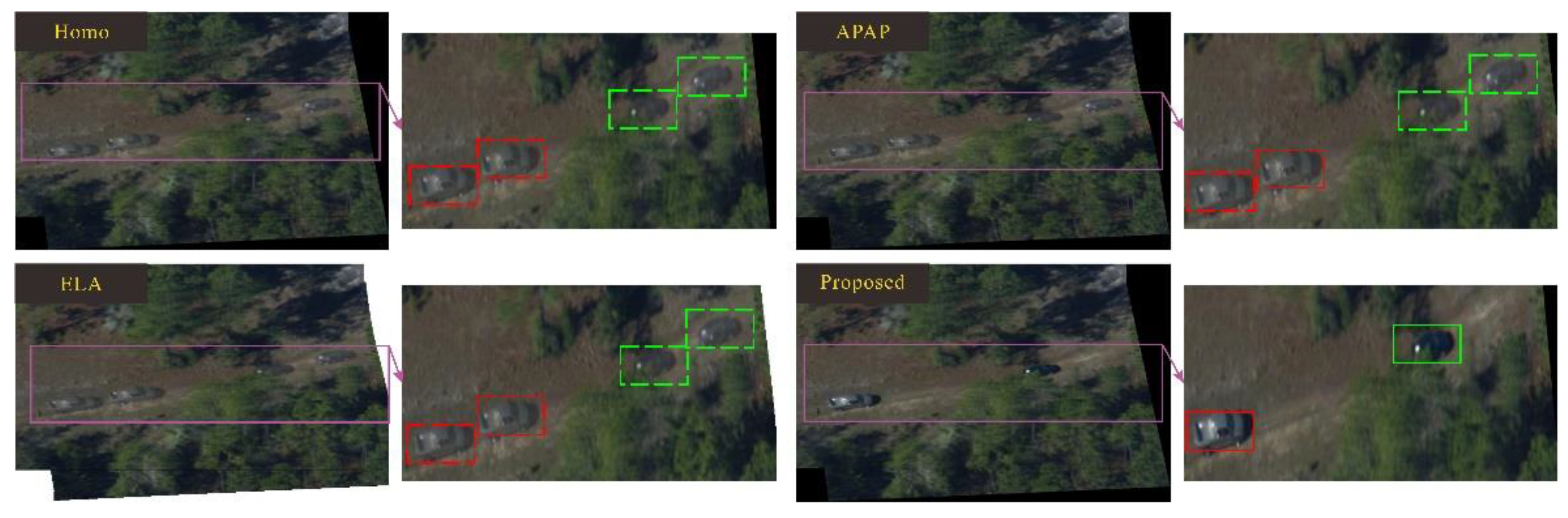
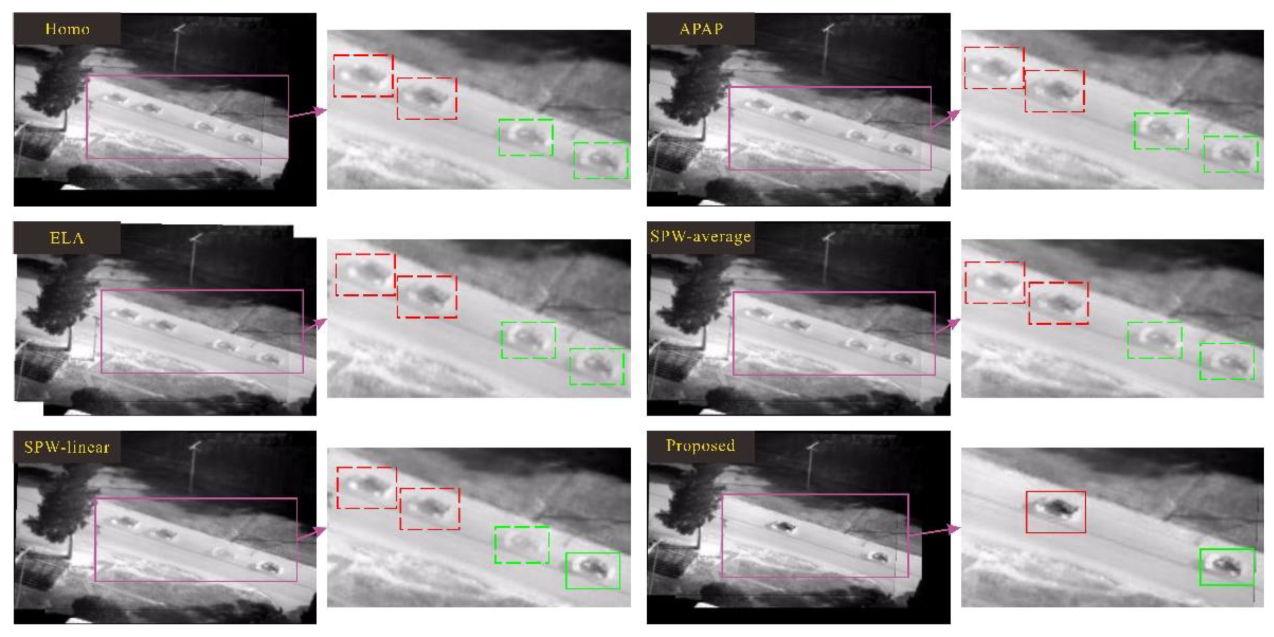
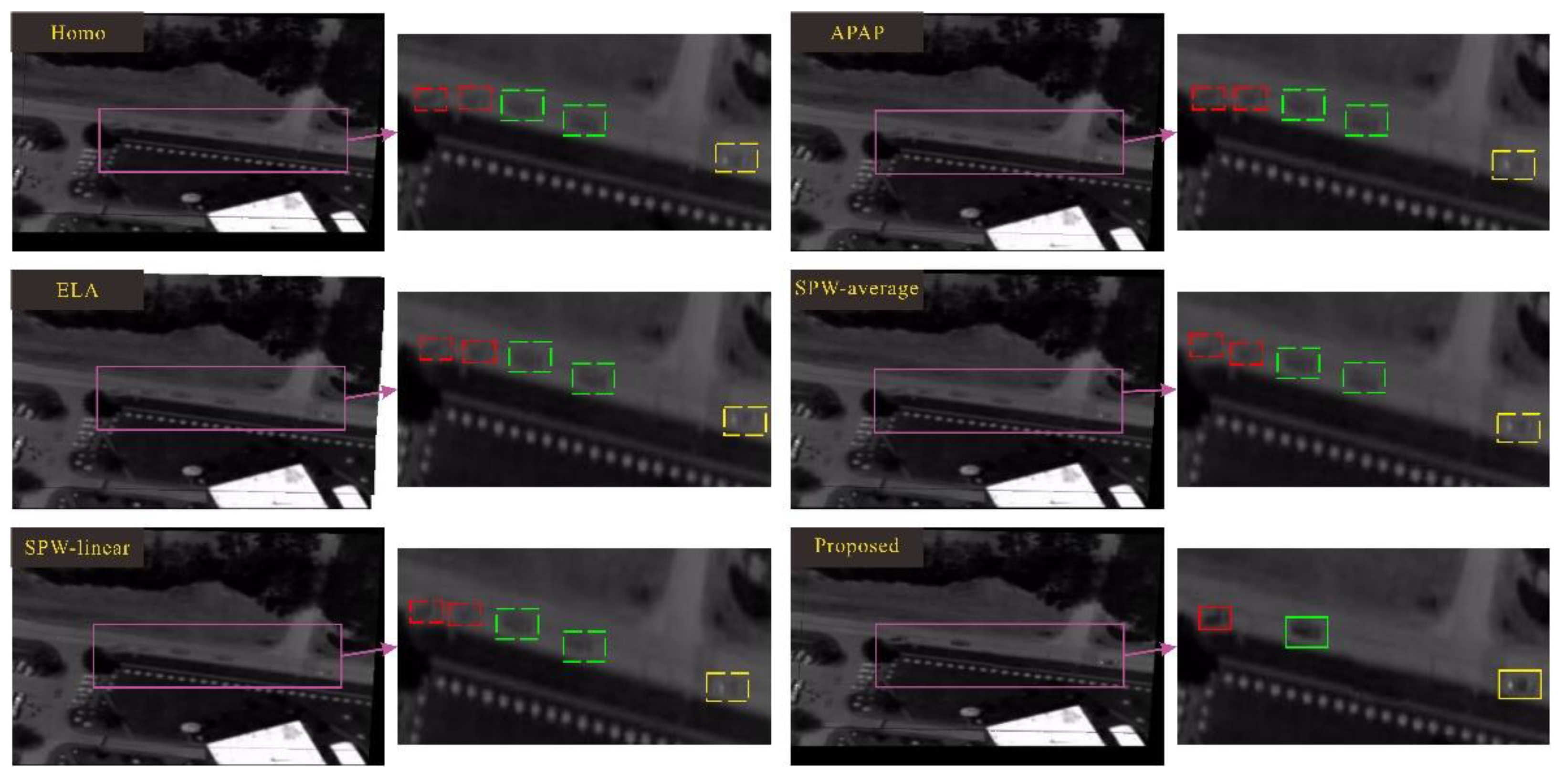
In this section, in order to show the effectiveness of the proposed method, we make a qualitative comparison by comparing four state-of-the-art methods: Homo, APAP, ELA and SPW. The comparison results are shown in Figure 11, Figure 12, Figure 13, Figure 14, Figure 15, Figure 16 and Figure 17.
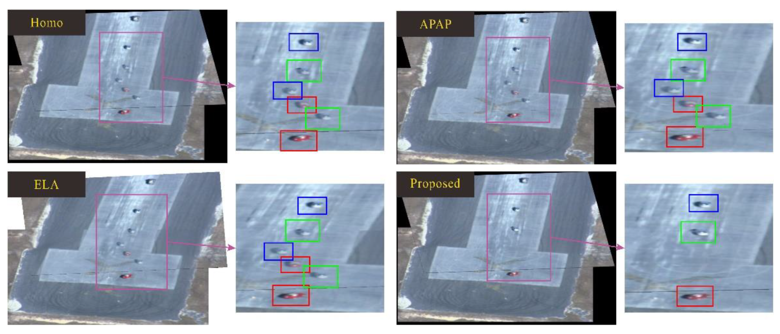
Figure 11 and Figure 12 show the comparison results of eg02 and eg03 data in the VIVID data set. There are multiple ghosts in each pair of stitched images. Different colored boxes represent different objects. Correspondingly, the same color box represents the same object. In the final stitching result, the same color box appears many times; that is, the object is repeatedly displayed, which violates the principle of object uniqueness. The dotted line box indicates that the object is as ghost, and the solid line box indicates a real object. In the result of the proposed method, the ghosts are eliminated to ensure that each object appears only once in the final mosaic result, and the object is not segmented.
Figure 13 and Figure 14 show the stitching results of eg01 and eg05 in VIVID, which are compared with Homo, APAP and ELA methods. It was not possible to stitch these two sets of data with the SPW method. Therefore, the results of only four methods are shown in Figures. As above, different colored boxes represent different objects, dotted boxes represent ghosts, and solid boxes represent real objects. Our results still exhibit advantages. In our final mosaic results, the objects are not repeated; at the same time, the objects only appear once, and they are real objects rather than ghosts.
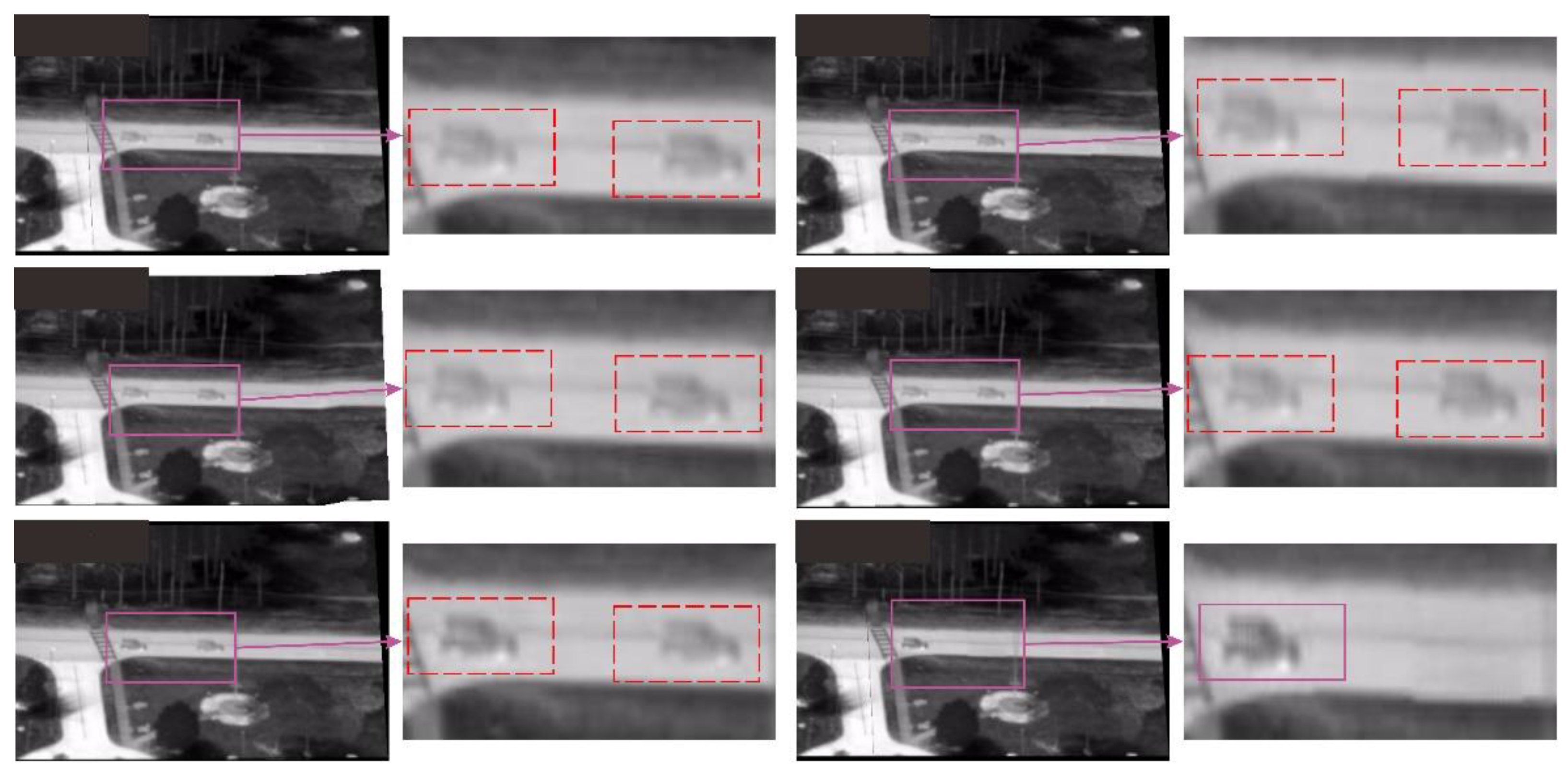
In particular, our method is also effective for dim images, and the results are shown in Figure 15, Figure 16 and Figure 17. The stitching results show another advantage of our method; that is, stitching dim images and removing ghosts.
In Figure 11, Figure 12, Figure 13, Figure 14, Figure 15, Figure 16 and Figure 17, we present experiments on eight data in the VIVID data set and compare four state-of-the-art methods. The results show that the proposed method is superior to other methods. Moreover, our method can not only mosaic UAV remote sensing images and eliminate ghosts but is also effective with multiple small objects in the scene, especially for low resolution and dim images.
4.5. User Study
In order to investigate whether our method would be popular with users, we performed a user study and compared it with four state-of-the-art methods: Homo, APAP, ELA and SPW. We invited 16 participants to vote on the results of eight data. All the eight data were from the VIVID data set, as shown above. The voting results of participants are shown in Table 4.
In Table 4, “S” means state-of-the-art methods (Homo, APAP, ELA, SPW) and “P” means the proposed method. Table 4 shows a summary of user voting. We calculated the score according to the voting results of 16 participants. The calculation method of the score is shown in Equation (5). This user study shows that the mosaic result of our proposed method won the favor of most users:
where, is the weight coefficient of voting, is the number of people who voted, () and is the number of votes.
5. Conclusions
In this paper, we have proposed a novel ghost removal method for UAV remote sensing image mosaics that can jointly identify ghosts and eliminate ghost areas without distortion, cutting and repetition. Our three main contributions to the final performance are as follows: firstly, in the ghost identification component, we proposed a mesh-based image difference method to detect significant moving objects as potential ghosts in two stitched images, which accurately correspond to the ghost pairs based on the object tracking method; secondly, we designed an image information source selection strategy in the image information source selection component to generate appropriate image information sources as potential ghosts for localization; finally, we designed a method based on Poisson fusion to further optimize the image block in the ghost elimination component to produce a natural mosaic image. We validated the proposed method on the VIVID data set and compared the proposed method with Homo, ELA, SPW and APAP using the PSNR evaluation indicator. The comparative results show that the results of the proposed method are superior to other methods. The proposed method has some limitations in threshold selection. In future work, an adaptive threshold adjustment method will be designed to select an appropriate threshold for each group of test images to improve the robustness of the method.
Author Contributions
W.X. managed the project, conceived the experiments, and assisted in writing the manuscript. Z.Z. designed the algorithm, conducted experiments, and led the writing of the manuscript. S.C. took part in designing experiments, and assisted in writing the manuscript. All authors have read and agreed to the published version of the manuscript.
Funding
This research was funded by the National Natural Science Foundation of China (Grant number 61906135, 62020106004, and 92048301) and the Tianjin Science and Technology Plan Project (Grant number 20JCQNJC01350). And the APC was funded by the National Natural Science Foundation of China (Grant number 61906135).
Institutional Review Board Statement
Not applicable.
Informed Consent Statement
Not applicable.
Data Availability Statement
Restrictions apply to the availability of these data. Data was obtained from VIVID Tracking Evaluation Web Site and are available at http://vision.cse.psu.edu/data/vividEval/datasets/datasets.htm (accessed on 1 March 2021) with the permission of the VIVID Tracking Evaluation Web Site.
Conflicts of Interest
The authors declare no conflict of interest.
References
- Herrmann, C.; Wang, C.; Bowen, R.; Keyder, E.; Zabih, R. Object-centered image stitching. In Proceedings of the European Conference on Computer Vision, Munich, Germany, 8–14 September 2018; pp. 846–861. [Google Scholar]
- Brown, M.; Lowe, D.G. Automatic panoramic image stitching using invariant features. Int. J. Comput. Vis. 2007, 74, 59–73. [Google Scholar] [CrossRef] [Green Version]
- Gao, J.; Kim, S.J.; Brown, M.S. Constructing image panoramas using dual-homography warping. In Proceedings of the IEEE International Conference on Computer Vision and Pattern Recognition, Colorado Springs, CO, USA, 20–25 June 2011; pp. 49–56. [Google Scholar]
- Lin, W.Y.; Liu, S.; Matsushita, Y.; Ng, T.T.; Cheong, L.F. Smoothly varying affine stitching. In Proceedings of the European Conference on Computer Vision, Colorado Springs, CO, USA, 20–25 June 2011; pp. 345–352. [Google Scholar]
- Zaragoza, J.; Chin, T.J.; Tran, Q.H.; Brown, M.S.; Suter, D. As-Projective-As-Possible Image Stitching with Moving DLT. IEEE Trans. Pattern Anal. Mach. Intell. 2014, 36, 1285–1298. [Google Scholar] [PubMed] [Green Version]
- Liu, S.; Chai, Q. Shape-Optimizing and Illumination-Smoothing Image Stitching. IEEE Trans. Multimed. 2019, 21, 690–703. [Google Scholar] [CrossRef]
- Lee, K.Y.; Sim, J.Y. Warping Residual Based Image Stitching for Large Parallax. In Proceedings of the IEEE International Conference on Computer Vision and Pattern Recognition, Seattle, WA, USA, 13–19 June 2020; pp. 8195–8203. [Google Scholar]
- Zheng, J.; Wang, Y.; Wang, H.; Li, B.; Hu, H.M. A Novel Projective-Consistent Plane Based Image Stitching Method. IEEE Trans. Multimed. 2019, 21, 2561–2575. [Google Scholar] [CrossRef]
- Li, J.; Wang, Z.; Lai, S.; Zhai, Y.; Zhang, M. Parallax-tolerant image stitching based on robust elastic warping. IEEE Trans. Multimed. 2018, 20, 1672–1687. [Google Scholar] [CrossRef]
- Xiang, T.Z.; Xia, G.S.; Bai, X.; Zhang, L. Image stitching by line-guided local warping with global similarity constraint. Pattern Recognit. 2018, 83, 481–497. [Google Scholar] [CrossRef] [Green Version]
- Lee, K.Y.; Sim, J.Y. Stitching for Multi-View Videos with Large Parallax Based on Adaptive Pixel Warping. IEEE Access 2018, 6, 26904–26917. [Google Scholar] [CrossRef]
- Chang, C.H.; Sato, Y.; Chuang, Y.Y. Shape-Preserving Half-Projective Warps for Image Stitching. In Proceedings of the IEEE International Conference on Computer Vision and Pattern Recognition, Columbus, OH, USA, 23–28 June 2014; pp. 3254–3261. [Google Scholar]
- Lin, C.C.; Pankanti, S.U.; Ramamurthy, K.N.; Aravkin, A.Y. Adaptive as-natural-as-possible image stitching. In Proceedings of the IEEE International Conference on Computer Vision and Pattern Recognition, Boston, MA, USA, 7–12 June 2015; pp. 1155–1163. [Google Scholar]
- Chen, Y.S.; Chuang, Y.Y. Natural Image Stitching with the Global Similarity Prior. In Proceedings of the European Conference on Computer Vision, Amsterdam, The Netherlands, 11–14 October 2016; pp. 186–201. [Google Scholar]
- Liao, T.; Li, N. Single-Perspective Warps in Natural Image Stitching. IEEE Trans. Image Process. 2020, 29, 724–735. [Google Scholar] [CrossRef] [PubMed] [Green Version]
- Li, N.; Xu, Y.; Wang, C. Quasi-Homography Warps in Image Stitching. IEEE Trans. Multimed. 2018, 20, 1365–1375. [Google Scholar] [CrossRef] [Green Version]
- Bryson, M.; Reid, A.; Ramos, F.; Sukkarieh, S. Airborne vision-based mapping and classification of large farmland environments. J. Field Robot. 2010, 27, 632–655. [Google Scholar] [CrossRef]
- Heinze, N.; Esswein, M.; Kruger, W.; Saur, G. Automatic image exploitation system for small UAVs. In Proceedings of the SPIE-The International Society for Optical Engineering, Orlando, FL, USA, 16–20 March 2008. [Google Scholar]
- Zhou, G. Near Real-Time Orthorectification and Mosaic of Small UAV Video Flow for Time-Critical Event Response. IEEE Trans. Geosci. Remote Sens. 2009, 47, 739–747. [Google Scholar] [CrossRef]
- Chen, C.S.; Chen, Y.T.; Huang, F. Stitching and Reconstruction of Linear-Pushbroom Panoramic Images for Planar Scenes. In Proceedings of the European Conference on Computer Vision, Prague, Czech Republic, 11–14 May 2004; pp. 190–201. [Google Scholar]
- Se, S.; Henry, D.; Firoozfam, P.; Goldstein, N.; Wu, L.; Dutkiewicz, M.; Pace, P.; Naud, J. Automated UAV-based mapping for airborne reconnaissance and video exploitation. In Proceedings of the SPIE—The International Society for Optical Engineering, Munich, Germany, 14–18 June 2009; p. 73070M. [Google Scholar]
- Hsu, S. Geocoded terrestrial mosaics using pose sensors and video registration. In Proceedings of the IEEE International Conference on Computer Vision and Pattern Recognition, Kauai, HI, USA, 8–14 December 2001. [Google Scholar]
- Yahyanejad, S.; Wischounig, D.; Quaritsch, M.; Rinner, B. Incremental Mosaicking of Images from Autonomous, Small-Scale UAVs. In Proceedings of the IEEE International Conference on Advanced Video and Signal Based Surveillance, Boston, MA, USA, 29 August–1 September 2010; pp. 329–336. [Google Scholar]
- Xu, Y.; Ou, J.; He, H.; Zhang, X.; Mills, J. Mosaicking of Unmanned Aerial Vehicle Imagery in the Absence of Camera Poses. Remote Sens. 2016, 8, 204. [Google Scholar] [CrossRef]
- Liu, J.; Gong, J.; Guo, B.; Zhang, W. A Novel Adjustment Model for Mosaicking Low-Overlap Sweeping Images. IEEE Trans. Geosci. Remote Sens. 2017, 55, 4089–4097. [Google Scholar] [CrossRef]
- Cai, G.; Su, S.Z.; Leng, C.; Wu, Y. A Robust Transform Estimator Based on Residual Analysis and Its Application on UAV Aerial Images. Remote Sens. 2018, 10, 291. [Google Scholar] [CrossRef] [Green Version]
- Kakli, M.U.; Cho, Y.; Seo, J. Minimization of Parallax Artifacts in Video Stitching for Moving Foregrounds. IEEE Access 2018, 6, 57763–57777. [Google Scholar] [CrossRef]
- Davis, J. Mosaics of scenes with moving objects. In Proceedings of the IEEE International Conference on Computer Vision and Pattern Recognition, Santa Barbara, CA, USA, 25 June 1998; pp. 354–360. [Google Scholar]
- Flores, A.; Belongie, S. Removing pedestrians from Google street view images. In Proceedings of the IEEE International Conference on Computer Vision and Pattern Recognition, San Francisco, CA, USA, 13–18 June 2010; pp. 53–58. [Google Scholar]
- Henriques, J.; Caseiro, R.; Martins, P.; Batista, J. High-Speed Tracking with Kernelized Correlation Filters. IEEE Trans. Pattern Anal. Mach. Intell. 2015, 37, 583–596. [Google Scholar] [CrossRef] [PubMed] [Green Version]
- Pérez, P.; Gangnet, M.; Blake, M. Poisson image editing. ACM Trans. Graph. 2003, 22, 313–318. [Google Scholar] [CrossRef]
- Lowe, D.G. Distinctive Image Features from Scale-Invariant Keypoints. Int. J. Comput. Vis. 2004, 60, 91–110. [Google Scholar] [CrossRef]
- Vedaldi, A.; Fulkerson, B. VLFeat: An open and portable library of computer vision algorithms. In Proceedings of the International Conference on Multimedea, Firenze, Italy, 25–29 October 2010; pp. 1469–1472. [Google Scholar]
- Fischler, M.A.; Bolles, R.C. Random Sample Consensus: A Paradigm for Model Fitting with Applications to Image Analysis and Automated Cartography. Commun. ACM 1981, 24, 381–395. [Google Scholar] [CrossRef]
- Liu, W.; Anguelov, D.; Erhan, D.; Szegedy, C.; Reed, S.; Fu, C.Y.; Berg, A.C. SSD: Single Shot MultiBox Detector. In Proceedings of the European Conference on Computer Vision, Amsterdam, The Netherlands, 11–14 October 2016; pp. 21–37. [Google Scholar]
Figure 1.
The collaboration flow of the three components.

Figure 2.
The trajectory of an object in multiple images.

Figure 3.
Schematic diagram of ghost performance.

Figure 4.
Meshing diagram.

Figure 5.
The overview of proposed method.

Figure 6.
The comparison of threshold .

Figure 7.
Comparison of smaller threshold and appropriate threshold.

Figure 8.
Comparison of larger threshold and appropriate threshold.

Figure 9.
An error case of an object detection method.

Figure 10.
The effectiveness of the mesh-based ghost identification method.

Figure 11.
Comparison between the proposed method and SOTA methods on eg02 data.

Figure 12.
Comparison between the proposed method and SOTA methods on eg03 data.

Figure 13.
Comparison between the proposed method and SOTA method on eg01 data.

Figure 14.
Comparison between the proposed method and SOTA methods on eg05 data.

Figure 15.
Comparison between the proposed method and SOTA methods on pk01 data.

Figure 16.
Comparison between the proposed method and SOTA methods on pk02 data.

Figure 17.
Comparison between the proposed method and SOTA methods on pk03 data.


Table 1.
Comparison between the SSD and the proposed mesh-based ghost identification method.
| Experimental Data (VIVID) | Proposed | SSD |
|---|---|---|
| eg01 | T | F |
| eg02 | T | F |
| eg03 | T | F |
| eg04 | T | F |
| eg05 | T | F |
| pk01 | T | F |
| pk02 | T | F |
| pk03 | T | E |
Table 2.
Comparison of processing time (unit: sec).
| Experimental Data (VIVID) | Homo | APAP | ELA | SPW | Proposed |
|---|---|---|---|---|---|
| eg01 | 12.4513 | 115.9844 | 13.256510 | - | 18.8906 |
| eg02 | 11.2969 | 131.7813 | 17.730541 | 50.3594 | 19.2188 |
| eg03 | 24.6719 | 160.3438 | 17.715818 | 50.5469 | 25.3125 |
| eg04 | 11.9219 | 134.9531 | 15.567404 | 55.2500 | 13.5156 |
| eg05 | 13.0938 | 113.4688 | 13.726297 | - | 20.2344 |
| pk01 | 16.9375 | 128.0938 | 13.371444 | 45.6875 | 19.8906 |
| pk02 | 9.8438 | 105.7719 | 15.592251 | 47.9219 | 18.1406 |
| pk03 | 10.2969 | 83.5781 | 17.370393 | 47.5313 | 14.9688 |
Table 3.
PSNR Value Comparison.
| Experimental Data (VIVID) | Homo | APAP | ELA | SPW | Proposed |
|---|---|---|---|---|---|
| eg01 | 20.2016 | 21.40845 | 22.5796 | - | 22.82165 |
| eg02 | 12.1815 | 23.2395 | 25.1985 | 22.9554 | 25.2624 |
| eg03 | 12.03825 | 19.7038 | 24.5577 | 19.43185 | 24.66515 |
| eg04 | 25.98565 | 26.3615 | 26.9716 | 25.85315 | 27.5436 |
| eg05 | 13.0429 | 27.6184 | 28.13995 | - | 28.1579 |
| pk01 | 11.9454 | 24.35365 | 26.56885 | 23.5627 | 27.1024 |
| pk02 | 19.99475 | 21.72835 | 22.9649 | 23.78245 | 23.80285 |
| pk03 | 12.81695 | 20.4451 | 16.83345 | 26.7951 | 27.75225 |
Table 4.
The results for the user study.
| Data | eg01 | eg02 | eg03 | eg04 | eg05 | pk01 | pk02 | pk03 | |||||||||
|---|---|---|---|---|---|---|---|---|---|---|---|---|---|---|---|---|---|
| User | S | P | S | P | S | P | S | P | S | P | S | P | S | P | S | P | |
| 01 | √ | √ | √ | √ | √ | √ | √ | √ | |||||||||
| 02 | √ | √ | √ | √ | √ | √ | √ | √ | |||||||||
| 03 | √ | √ | √ | √ | √ | √ | √ | √ | |||||||||
| 04 | √ | √ | √ | √ | √ | √ | √ | √ | |||||||||
| 05 | √ | √ | √ | √ | √ | √ | √ | √ | |||||||||
| 06 | √ | √ | √ | √ | √ | √ | √ | √ | |||||||||
| 07 | √ | √ | √ | √ | √ | √ | √ | √ | |||||||||
| 08 | √ | √ | √ | √ | √ | √ | √ | √ | |||||||||
| 09 | √ | √ | √ | √ | √ | √ | √ | √ | |||||||||
| 10 | √ | √ | √ | √ | √ | √ | √ | √ | |||||||||
| 11 | √ | √ | √ | √ | √ | √ | √ | √ | |||||||||
| 12 | √ | √ | √ | √ | √ | √ | √ | √ | |||||||||
| 13 | √ | √ | √ | √ | √ | √ | √ | √ | |||||||||
| 14 | √ | √ | √ | √ | √ | √ | √ | √ | |||||||||
| 15 | √ | √ | √ | √ | √ | √ | √ | √ | |||||||||
| 16 | √ | √ | √ | √ | √ | √ | √ | √ | |||||||||
| Score | 6.25 | 93.75 | 6.25 | 93.75 | 0 | 100 | 12.5 | 87.5 | 0 | 100 | 6.25 | 93.75 | 6.25 | 93.75 | 6.25 | 93.75 | |
Publisher’s Note: MDPI stays neutral with regard to jurisdictional claims in published maps and institutional affiliations. |
© 2021 by the authors. Licensee MDPI, Basel, Switzerland. This article is an open access article distributed under the terms and conditions of the Creative Commons Attribution (CC BY) license (https://creativecommons.org/licenses/by/4.0/).
Share and Cite
MDPI and ACS Style
Xue, W.; Zhang, Z.; Chen, S. Ghost Elimination via Multi-Component Collaboration for Unmanned Aerial Vehicle Remote Sensing Image Stitching. Remote Sens. 2021, 13, 1388. https://0-doi-org.brum.beds.ac.uk/10.3390/rs13071388
AMA Style
Xue W, Zhang Z, Chen S. Ghost Elimination via Multi-Component Collaboration for Unmanned Aerial Vehicle Remote Sensing Image Stitching. Remote Sensing. 2021; 13(7):1388. https://0-doi-org.brum.beds.ac.uk/10.3390/rs13071388
Chicago/Turabian StyleXue, Wanli, Zhe Zhang, and Shengyong Chen. 2021. "Ghost Elimination via Multi-Component Collaboration for Unmanned Aerial Vehicle Remote Sensing Image Stitching" Remote Sensing 13, no. 7: 1388. https://0-doi-org.brum.beds.ac.uk/10.3390/rs13071388
Note that from the first issue of 2016, this journal uses article numbers instead of page numbers. See further details here.