
Autonomous Integrity Monitoring for Relative Navigation of Multiple Unmanned Aerial Vehicles

School of Electronics Engineering, Beijing University of Posts and Telecommunications, Beijing 100876, China
Remote Sens. 2021, 13(8), 1483; https://0-doi-org.brum.beds.ac.uk/10.3390/rs13081483
Submission received: 16 March 2021
/
Revised: 7 April 2021
/
Accepted: 9 April 2021
/
Published: 12 April 2021
(This article belongs to the Special Issue Multi-Sensor Data Fusion of Unmanned Aerial Vehicles (UAVs) Remote Sensing for Environmental Applications)
Abstract
:Accurate and reliable relative navigation is the prerequisite to guarantee the effectiveness and safety of various multiple Unmanned Aerial Vehicles (UAVs) cooperation tasks, when absolute position information is unavailable or inaccurate. Among the UAV navigation techniques, Global Navigation Satellite System (GNSS) is widely used due to its worldwide coverage and simplicity in relative navigation. However, the observations of GNSS are vulnerable to different kinds of faults arising from transmission degradation, ionospheric scintillations, multipath, spoofing, and many other factors. In an effort to improve the reliability of multi-UAV relative navigation, an autonomous integrity monitoring method is proposed with a fusion of double differenced GNSS pseudoranges and Ultra Wide Band (UWB) ranging units. Specifically, the proposed method is designed to detect and exclude the fault observations effectively through a consistency check algorithm in the relative positioning system of the UAVs. Additionally, the protection level for multi-UAV relative navigation is estimated to evaluate whether the performance meets the formation flight and collision avoidance requirements. Simulated experiments derived from the real data are designed to verify the effectiveness of the proposed method in autonomous integrity monitoring for multi-UAV relative navigation.
1. Introduction
Nowadays, multiple Unmanned Aerial Vehicles (UAVs) cooperation is playing an important role in various civilian and military applications, such as remote sensing, packet delivery, flight show, and low altitude surveillance [1,2,3]. During the process of multi-UAV applications, the scheduled missions are usually completed cooperatively and efficiently through information synchronization, formation keeping, path planning, and many other applications. For high-precision multi-UAV systems, one of the most important keys to guarantee the effectiveness and safety is an accurate and reliable “relative navigation”–the relative positions of a UAV with respect to the others. For example, during multi-UAV remote sensing missions, the relative navigation solutions amongst the UAVs must be precisely known to synthesize a single large imaging aperture using all the measurements of the formation flying UAVs [4]. For flight show missions, a stringent navigation performance on a relative position is required for each UAV to display different formations in order to obtain an impressive show effect and avoid collision accidents [5].
The relative positions amongst the UAVs can be obtained using the relative range and bearing data of navigation sensors in the case when the absolute positioning data are unavailable or inaccurate [6]. The commonly used relative navigation techniques for UAVs include Global Navigation Satellite System (GNSS), Ultra Wide Band (UWB), vision system, radar, and many other sensors [7,8]. In particular, GNSS is the main source to measure the position due to its potential for high accuracy implementation, worldwide coverage and simplicity in relative navigation. Nevertheless, since the nominal accuracy of a stand-alone GNSS absolute positioning is about a few meters, the relative position by differencing two absolute positions may be unable to meet the requirements of some high-accuracy applications. To solve this problem, improved solutions, the so-called Real-Time Kinematic (RTK) and Differential GNSS (DGNSS), are commonly applied to obtain a much more accurate relative navigation for the multi-UAV system [9,10]. Studies on RTK have been actively conducted to accurately estimate the relative location of UAVs at centimeter-level, while the solutions might be unstable due to computing complexity in determining the integer carrier-cycle ambiguities [11]. Considering that GNSS pseudorange is more stable and continuous than carrier phase, differenced GNSS pseudoranges are usually used to improve the availability of multi-UAV navigation systems [12].
Although GNSS-based high accuracy relative positioning can be obtained for multi-UAV, the observations of GNSS still suffer from different kinds of faults due to transmission degradation, ionospheric scintillations, multipath, spoofing, and many other factors. These faults will bring catastrophic consequences to the multi-UAV system [13,14,15]. On the one hand, the relative positioning failure of a UAV will be input and mislead the flight control system directly. On the other hand, since each UAV uses the relative position, one positioning failure might be spread and corrupted throughout the UAV network, which poses a serious threat to mission completion and flight safety. Thus, to improve the reliability of multi-UAV relative navigation, the fault observations should be detected and excluded effectively.
Integrity monitoring is one criterion to evaluate GNSS performance, which refers to the capability of the system to detect faults and warn the user when the system should not be used [16,17,18]. Although the related work, such as Receiver Autonomous Integrity Monitoring (RAIM) [19,20], has been a topic of constant research in the community of GNSS absolute positioning, research about integrity in relative positioning for multi-UAV is relatively poor. During the last few years, several methods have been proposed to improve the integrity of UAVs navigation. For example, to meet the high-accuracy requirements for multiple moving platforms applications, Sun et al. proposed a fault detection and exclusion method for relative positioning using carrier phase [21]. However, as mentioned in [22], carrier phase measurements might suffer from cycle slip problems. Instead, double differenced pseudoranges were employed for integrity monitoring of relative navigation systems for multi-UAV in urban dynamic applications, and the relative protection level was proposed for collision avoidance. Nevertheless, one main bottleneck of the two methods might be that they detected the faulty observations by exploiting the redundancy of stand-alone GNSS signals to check the measurement consistency. To further improve the integrity of the navigation system, some other sensors or datasets were adopted as aids to provide additional measurements for integrity monitoring. Groves et al. proposed a processing architecture for high-integrity carrier-phase relative Global Positioning System (GPS)/Inertial Navigation System (INS), while the error of the INS may drift over time and contaminate the integrity result [23]. Calhoun et al. proposed a vision-based precision relative navigation system for determining uncertainty and integrity [24]. An integration of inertial, vision and Differential GPS (DGPS) was proposed to increase the reliability of UAV sensor fault detection and identification in [25]. However, the performance of the vision system suffers greatly from occlusion and lighting conditions, which is unpredictable in high dynamic UAV applications. Terrestrial signals of opportunity (including cellular signals, digital television signals, and low Earth orbit satellite signals) were applied for the UAV integrity monitoring improvement [26], while the signals of opportunity might not always be available in the environments. The concept of integrity for cooperative systems has also been investigated in intelligent transportation systems. In urban vehicular scenarios, GNSS measurements from all the collaborators were used to improve the detection of faulty GNSS measurements [27,28]. With the aid of vehicle-to-vehicle communication, an autonomous integrity monitoring method was researched for real-time relative positioning systems based on a fusing of GNSS pseudoranges and Dedicated Short Range Communication (DSRC) measurements [29]. More recently, also for vehicular cooperative positioning in urban scenarios, a cooperative integrity monitoring method was proposed based on an extended Kalman filter [30].
To improve the performance of autonomous integrity monitoring for multi-UAV relative navigation, a novel method is proposed with the fusion of the double differenced GNSS pseudoranges and the UWB ranging units. Compared with other sensing devices obtaining relative navigation measurements, UWB stands out in accurate and reliable ranging due to its ability to alleviate multipath effects and robustness to light changing [31,32]. Inspired by the existing work of UWB positioning system, this paper proposes a new method using the relative distance measurement of UWB signals as an aid to improve the integrity performance of multi-UAV relative navigation. First, a new framework of autonomous integrity monitoring for multi-UAV relative navigation is proposed. Then, the proposed method is designed to detect and exclude the fault observations through a consistency check in the relative position of multi-UAV using double differenced GNSS pseudoranges and UWB relative range observations. Note that this work only considers the faults on GNSS observations, while the problem of fault detection and exclusion for multiple sensors of a cooperative system in the concept of integrity will be researched in the future, which is usually regarded to be much more difficult [30]. Finally, the protection level for multi-UAV relative navigation is calculated, which is used to advise whether to meet the requirements of the flight mission. To verify the effectiveness of the proposed method in autonomous integrity monitoring for multi-UAV relative navigation, simulated experiments derived from the real data are designed. The experimental results show that the proposed method outperforms the baseline integrity monitoring method in fault detection and exclusion.
The remainder of this paper is organized as follows. Section 2 is the details of the proposed integrity monitoring for multi-UAV relative navigation, including the descriptions of the framework, the fault detection and exclusion method, and the protection level estimation. Section 3 shows and discusses the experimental results. Finally, the conclusions are shown in Section 4.
2. Integrity Monitoring for Multi-UAV Relative Navigation
In this section, the details of the proposed integrity monitoring for multi-UAV relative navigation are illustrated as follows. First, the framework of the proposed method is presented. Then, the fault detection and exclusion method based on double differenced GNSS pseudoranges and UWB ranging units is proposed, followed by the protection level estimation method for multi-UAV relative navigation.
2.1. Framework
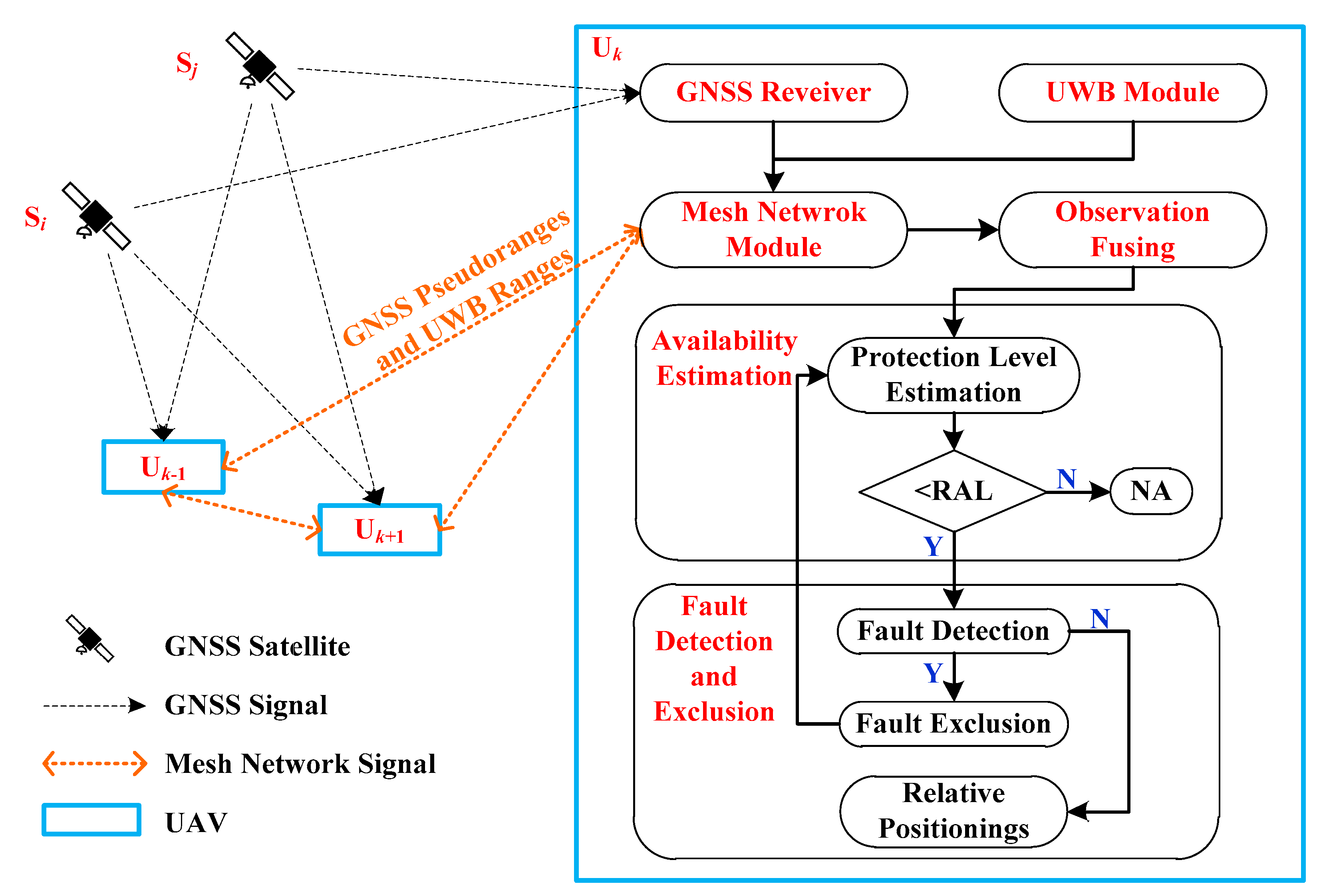
The goal of this paper is to develop a highly reliable relative navigation system for multiple UAVs. To achieve this, an autonomous integrity monitoring method for multi-UAV relative navigation based on GNSS and UWB observations is proposed. The framework of the proposed method is shown in Figure 1.
Given a multi-UAV system consisting of UAVs (i.e., , with ), each UAV obtains the pseudorange observations of visible GNSS satellites (, and other visible satellites) through an onboard GNSS receiver. Simultaneously, an onboard UWB module is applied to synchronously obtain the UWB ranging units for UAV relative distance measurements [33].
Then, during the multi-UAV cooperation, the GNSS pseudorange observation and UWB range information are shared by a mesh network module through which any two UAVs can be connected wirelessly. As shown in Figure 1, for each UAV, such as , its available neighbor UAVs are connected through the mesh network to obtain the UWB ranging units, which are fused with the double differenced GNSS pseudoranges to construct the observation formulas for relative positioning and autonomous integrity monitoring solutions. To improve the integrity monitoring performance of the multi-UAV relative navigation system, the availability is firstly estimated and the fault detection and exclusion method is followed. Specifically, the relative protection level is estimated and then compared with Relative Alert Level (RAL) to guarantee that the relative position error between each pair of UAVs will not be exceeded without being detected. If the relative protection level is not smaller than the RAL, the Not Available (NA) message will be sent to the system. Otherwise, fault detection is processed through a consistency check amongst the relative observations. If there is an alarm of the fault detection, fault exclusion is applied to find and exclude the observation faults. The availability estimation, fault detection, and fault exclusion are loop executed until there is no alarm of the fault detection. Finally, the remaining observations are used to calculate the relative positioning between each pair of UAVs through weighted least squares methods or other methods based on Kalman filters [31].
2.2. Fault Detection and Exclusion for Relative Navigation
2.2.1. Observations for Relative Navigation
Under the framework of the proposed method, a new GNSS autonomous integrity monitoring method is proposed for multi-UAV relative navigation with the aid of UWB systems. The two kinds of relative navigation observations of GNSS and UWB are presented as follows.
(1) Double differenced GNSS pseudoranges
Since the carrier phase measurements of GNSS might suffer from frequent cycle slip problems, in this paper, double differenced GNSS pseudoranges are employed to improve the observation stability for multi-UAV relative navigation.
The raw GNSS pseudorange observations are contaminated by different kinds of errors when the satellite signals are transmitted from the satellite to the UAV receiver. The main sources of error in GNSS pseudoranges combine receiver-independent errors (i.e., satellite ephemeris and clock errors, ionosphere and troposphere errors) and receiver-dependent errors (i.e., clock offsets, receiver errors) [34]. Since the baseline distance between two neighbor UAVs is typically negligible when compared with the 20,000-km altitude of the GNSS satellites, the receiver-independent errors for two GNSS receivers of each UAV end can be regarded as similar. Then the double differenced GNSS pseudoranges method can be applied to eliminate the common errors for an accurate relative location.
Given two different UAVs , (with and ) and a common visible satellite Si, the raw GNSS pseudorange of each UAV can be obtained as
where is the geometric distance between the satellite and UAV ; and are the satellite ephemeris and clock error of the satellite , respectively; is the light speed; , , are the ionosphere error, troposphere error, receiver clock offset, respectively; collects other errors such as receiver errors and residual errors, which is regarded as Gaussian noise. is a fault bias on the pseudorange , which might be caused by multipath interference, receiver fault, spoofing, and many other factors. For the fault free observation, .
Through Equation (1), the single differenced GNSS pseudoranges of and can be obtained
where the common receiver-independent errors, i.e., satellite ephemeris and clock errors, ionosphere and troposphere errors, are eliminated and , .
Then, the single differenced GNSS pseudoranges of satellite and satellite are used to calculate the double differenced GNSS pseudoranges as
where , .
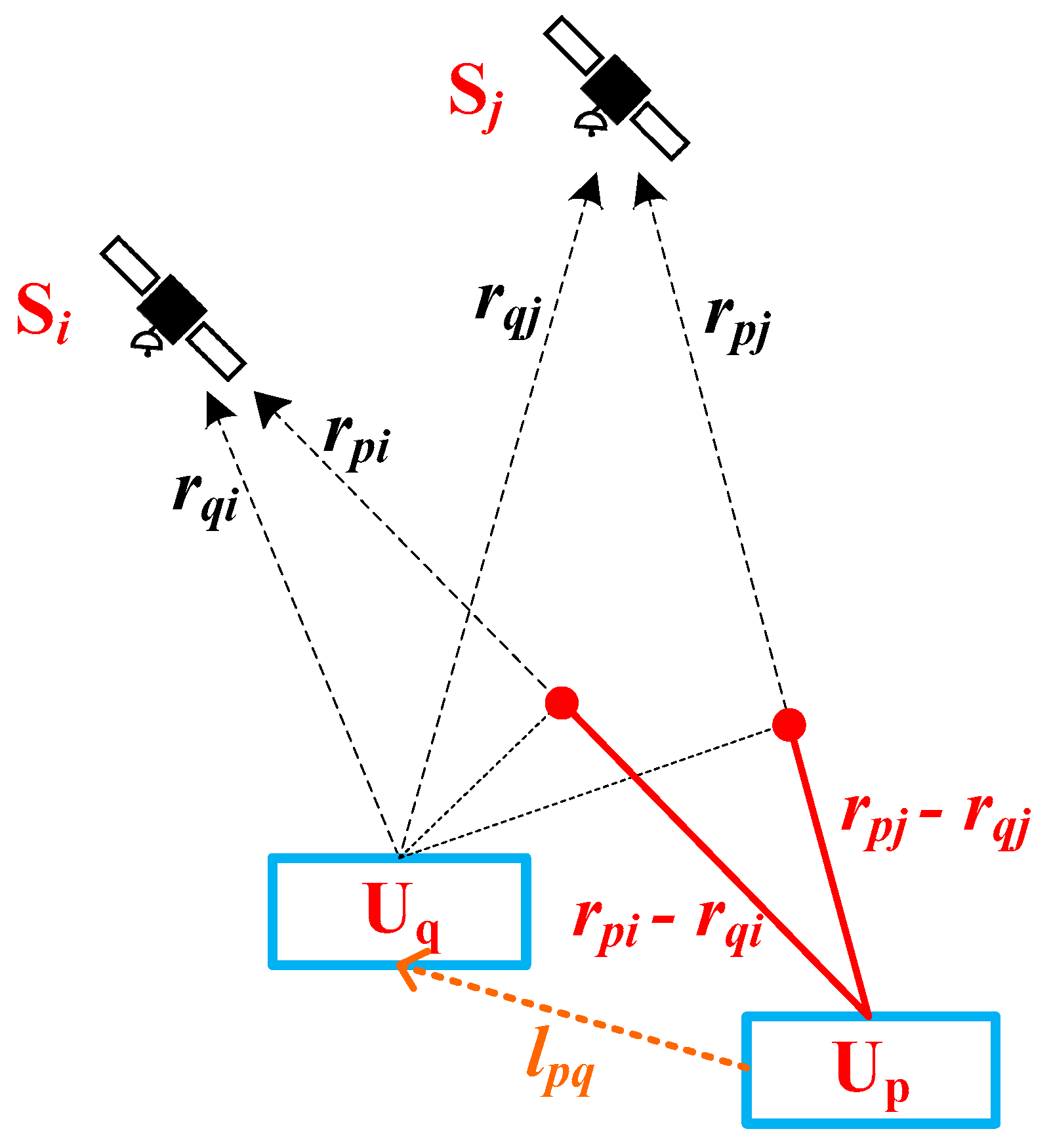
Note the baseline vector from UAV to UAV as with three dimension position in East-North-Up (ENU) coordinate system, and denote the line-of-sight vectors of from each UAV to the satellite as and in ENU coordinate system for . Since the altitude of a GNSS satellite is typically much larger than the baseline vector length, the line-of-sight vectors of each UAV to the satellite can be regarded as parallel. Thus, the normalized line-of-sight vector to the satellites can be obtained as
As shown in Figure 2, the single differenced geometric distance in Equation (3) can be obtained as
where is the scalar product between vectors.
Substituting Equation (5) into Equation (3) yields the double differenced GNSS pseudoranges,
Note the number of common visible satellites for and as . Usually, the satellite with the highest elevation angle is chosen as the reference satellite to obtain double differenced GNSS pseudorange observations [35]. Note the reference satellite as . Then, equations are obtained as Equation 6 by setting and , i.e.,
With Equation (7), the double differenced pseudorange measurement formulation of a constellation (such as GPS constellation) can be rewritten as
where is the measurement error of double differenced GPS pseudoranges, which follows a normal distribution with zero mean and covariance matrix .
Through Equation (8), the relative positioning solution can be obtained using the weighted least squares method, while the relative positioning vector of other constellations can be obtained in the same way.
(2) UWB observations
To obtain the distance between two UAVs, the time of flight of the UWB signal from the emitter UAV to the receiver UAV is estimated and then multiplied by the speed of light . In this paper, a two-way ranging method is applied to obtain the UWB ranging observations [33], which can get centimeter-level error distances within a few hundred meters range.
In this work, UWB measurement is used as direct measurement of the baseline distance. In order to simplify the procedure for data fusing, the linearized UWB observations formula is utilized in a similar way to GNSS observations [34],
where is the measurement error of the UWB system, which is assumed to follow a normal distribution with zero mean and covariance matrix . To be simplified, this work assumes the covariance matrix of UWB for each pair of UAVs to be independent and identically distributed. is the normalized line-of-sight vector from to , which is estimated using the relative positioning solution during the iteration in this paper. is the fault of UWB observation, which is assumed to be zero due to the simplify and robustness of the UWB system. Details about the UWB failure models will be further researched in the future.
(3) Observation fusing
Stacking Equations (8) and (9), the observation fusing of double differenced GPS pseudoranges and UWB ranging units can be obtained as
which can be rewritten as
where the random error follows a normal distribution with zero mean and a diagonal covariance matrix by assuming the independence between GPS and UWB measurements [31] as
With the aid of UWB measurements, the over-determined integrated system can improve the integrity performance for multi-UAV relative navigation. Note that, as the sampling rate of UWB systems can be much higher than GNSS receiver, the UWB observations can be down-sampled to obtain the synchronous GNSS observations and UWB observations. Moreover, there might be a lever-arm between the GNSS antenna and the UWB antenna on a UAV, which is calibrated in real applications.
2.2.2. Fault Detection
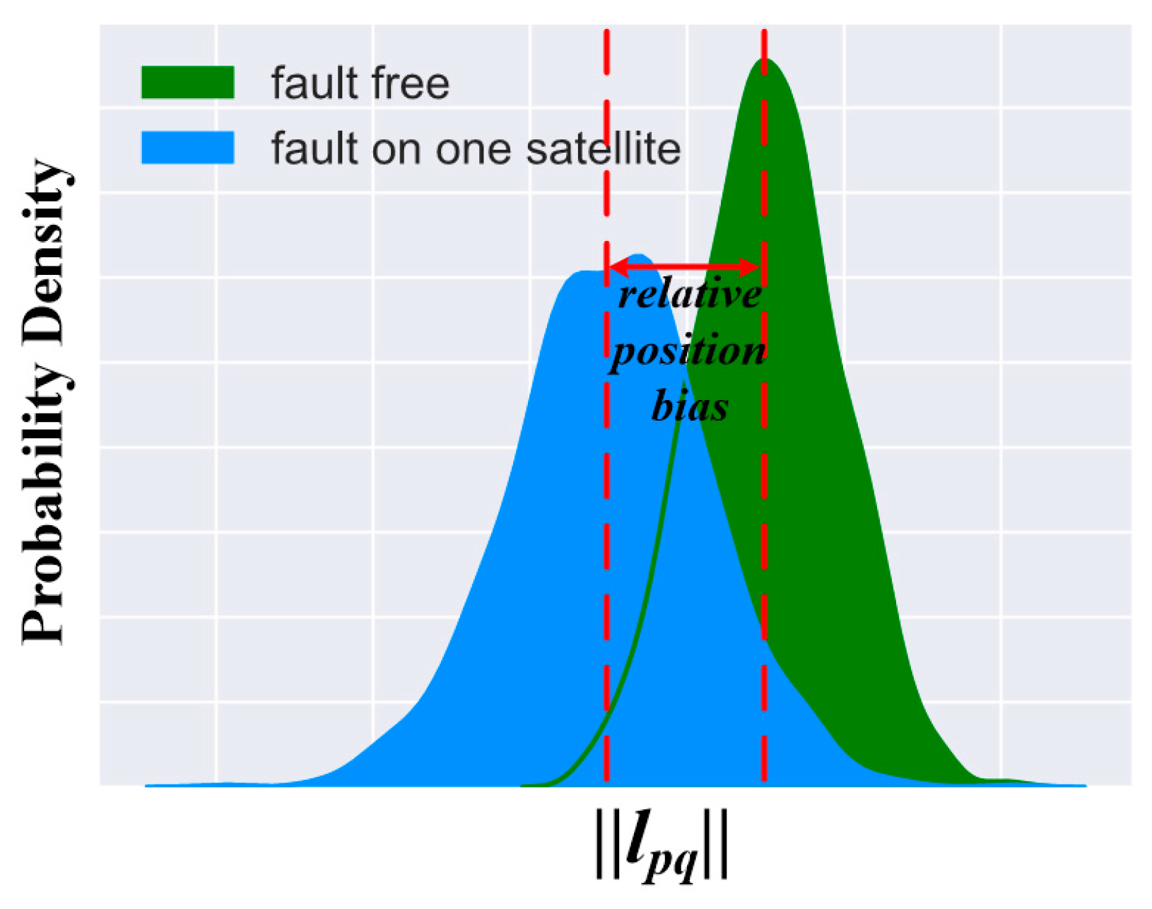
As discussed above, the observations of GNSS are vulnerable to different kinds of faults, which would cause a relative position bias for each pair of UAVs, as shown in Figure 3. Thus, the annoying faults should be detected to avoid catastrophic consequences for multi-UAV systems.
The core idea of fault detection for integrity monitoring is to check the consistency of the over-determined observations [36]. In this section, the residual-based snapshot method for multi-sensor integration system is applied to detect the fault for relative navigation [15]. Given the measurement model in Equation (11), the weighted least-squares solution for the estimation of is given by
where .
Then, the residual vector is defined as
Substituting Equation (13) into Equation (14), yields,
Note , where is a
by identity matrix, the residual vector above can be obtained as
With Equation (16), the test statistic Sum of Squared Errors (SSE) of the integrity monitoring for relative navigation is given by
When there is a fault in the observations, i.e., , the SSE follows a noncentral chi-squared distribution with degrees of freedom, and noncentrality parameter . Similar to the existing RAIM method [37], the fault detection method is to use the centralized distribution to determine the detection threshold .
Given a fault alarm requirement , the detection threshold can be obtained offline by solving the following equation [37]
where is the Gamma function, is the natural constant. The fault alarm is set to as in [38].
Once the test statistic exceeds the threshold , the normalized observation residuals is considered to not obey the centralized distribution, that is, the pseudorange observation is faulty. If the fault does not exist, it is called a false alarm.
2.2.3. Fault Exclusion
The purpose of fault exclusion is to not immediately stop using relative navigation when a fault is detected, thereby improving the continuity of the system. If the fault detection warning is sent to the system, fault identification and exclusion are processed using a leverage-based fault identification method [39], and the index of the most likely fault can be calculated by
where and is the column vector and the diagonal element of matrix , respectively.
The fault detection and fault exclusion is processed alternately until no alert is raised by the fault detector or the system is unavailable for relative navigation.
2.3. Protection Level Estimation for Relative Navigation
Protection level is originally used for evaluating the integrity performance in absolute navigation systems, which is a statistical error bound computed so as to guarantee that the probability of the absolute position error exceeding the said number is lower than the target integrity risk. In this paper, Relative Protection Level (RPL) is used because the integrity of this work is considered for relative navigation. RAL is defined as the relative error tolerance a system has, which cannot be exceeded without issuing a warning. To obtain the level of safety for relative navigation, RPL is estimated and compared with the required RAL in horizontal/vertical coordinate to evaluate the availability of the system. However, there is still no RAL indicator for multi-UAV systems, which will be further researched in the future.
Note that the fault hypothesis for different fault models in , and is a fault free model. Then the allocated integrity risk under hypothesis can be defined as [40]
where integrity risk is a function of the probability of the relative position error exceeding the protection level to be estimated , the prior probability of hypothesis , hypothesis , and the miss detection rate . The integrity risk for each hypothesis including is defined to accommodate all possible bias sizes. The final protection level for relative navigation is the maximum one among all hypotheses. In this paper, the risk for each hypothesis is set as , [40].
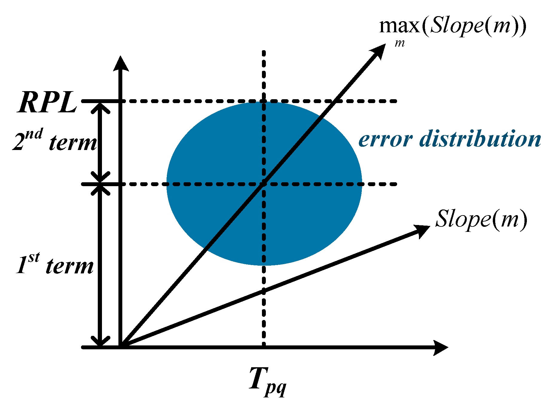
The relative protection level can also be divided into Relative Horizontal Protection Level (RHPL) and Relative Vertical Protection Level (RVPL). However, an accurate relative protection level calculating in Equation (20) can be very complex and time consuming [41]. Thus, to simplify the process, the protection level is approximately estimated as [15]
where is the inverse of the cumulative distribution function of a Gaussian random variable with zero mean and unit variance. , and are the diagonal elements of , and the slope for RHPL and RVPL can be obtained as
where , and are the elements of matrix , respectively.
The RHPL (or RVPL) in Equation (21) (or Equation (22)) consists of two terms. The first term is the maximum slope value multiplied by the detection threshold , and the second term is the inverse of the cumulative error distribution. For a better visualization, the calculation of RPL aggregated from the two terms is shown in Figure 4.
The estimated relative protection level is the position error that the algorithm guarantees will not be exceeded without being detected, which can be used to test the availability of the navigation system for multi-UAV relative navigation requirements. If the relative protection level in Equations (21) and (22) is larger than the required RAL or the number of common visible satellites for two UAVs is less than five, the not available message will be sent to the system.
3. Results
In this section, two separate simulated experiments derived from the real flight data are designed to verify the effectiveness of the proposed method in autonomous integrity monitoring for multi-UAV relative navigation. The first experiment is to evaluate the fault detection and exclusion performance of the proposed method, which is compared with the stand-alone GPS-based baseline method. The second experiment is to test the performance of relative protection level in real applications. Note that this work adopts GPS only for an example. The work can be easily extended to other constellations and multi-constellations.
3.1. Data and Experimental Setup
In order to illustrate the performance of the proposed integrity monitoring method for relative navigation, a real multi-UAV formation-keeping flight is conducted. In the experiments, three in-house quadrotor drones are used to set up the experiments, each of which carries a GPS receiver and a UWB module. The descriptions of the products are shown in Table 1, where RMSE is short for root mean square error.
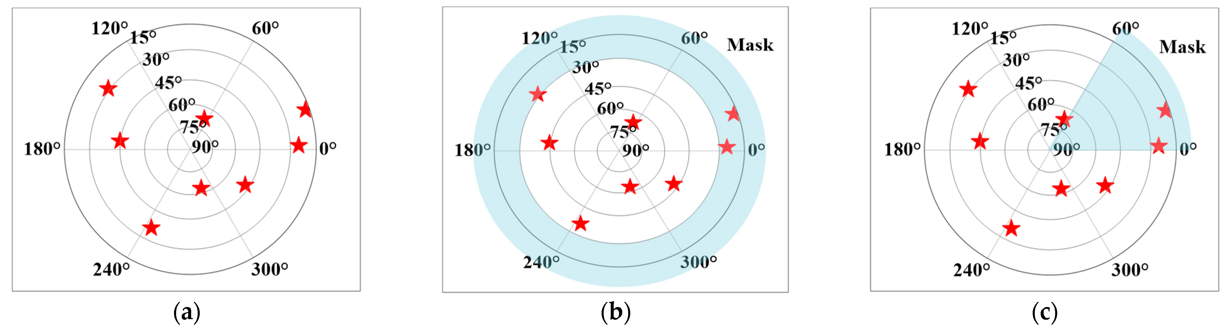
For safety concerns, these three drones in the experiments fly 4 km over an open lake along a rectangle trajectory during each sortie, and the total flight is composed of 10 sorties. During the flying process, the UAV formation is kept as an equilateral triangle with a constant side length. The constant side length changes from 10 to 100 m. The GPS receiver elevation mask angle is set to 15 degrees, as shown in Figure 5a. The dual frequency RTK technology is applied to provide positioning results up to centimeter-level accuracy, which can be regarded as the true position of the UAVs. Considering that the real GPS data with fault events are very difficult to obtain in practice, a manual fault event is added to the observations of the real data. The UWB observations are down-sampled to obtain the synchronous GPS observations and UWB observations, and the total amount of data for the experiments are samples of GPS and UWB observations.
To simulate a complex multi-UAV flight environment, some of the visible satellites are manually removed to verify the performance of the proposed algorithm under different receiving conditions. These experimental setups are used to verify the advantages of the proposed method from the perspective of geometric distribution and redundancy of the observations. Considering the influence of the geometric distribution and the redundancy on the performance results, the following three forms of conditions are designed as shown in Figure 5. Case I: Figure 5a shows the original satellite observations of the receiver, which consists of eight visible satellites. Case II: Figure 5b sets the receiver elevation mask angle to 30 degrees, which simulates a flying environment with more occlusion around. Case III: Figure 5c sets a 60 degree azimuth mask, which is dynamic and overlapping with the other two UAVs. Experimental results show that the UAVs cooperation can be used to significantly improve the integrity monitoring performance of relative navigation to compensate for partial occlusion.
3.2. Results of Fault Detection and Exclusion
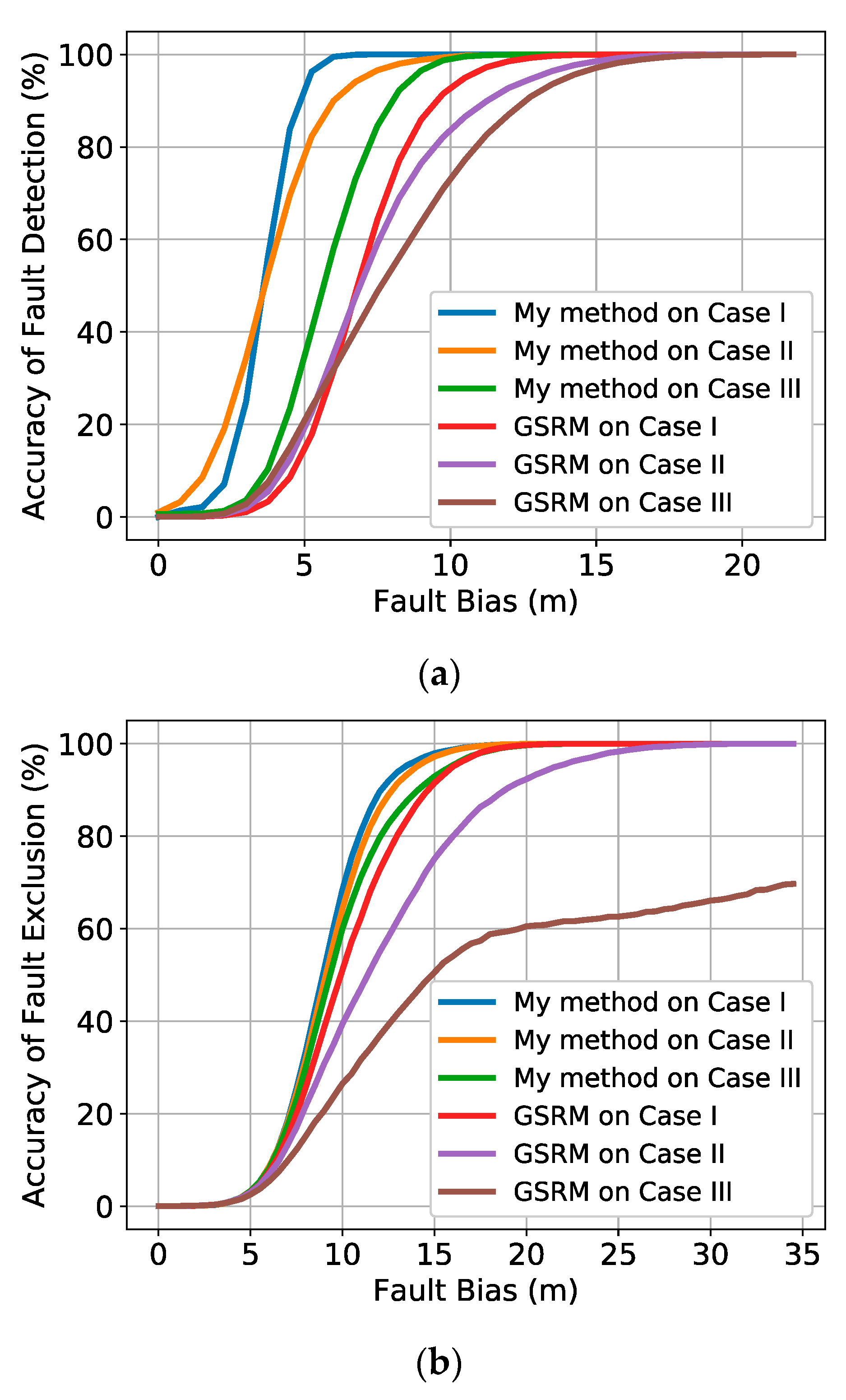
To evaluate the performance of the proposed approach, the GPS stand-alone RAIM method (GSRM) is applied for a comparison in terms of fault detection and exclusion. The simulations randomly selected one visual satellite and added the fault bias on the pseudorange. The fault detection and exclusion results with different methods are shown in Figure 6, which shows that the proposed method performs better than the GSRM with a higher fault detection and exclusion rate under the conditions of the same fault.
In terms of fault detection in Figure 6a, the experimental results show that the relative ranging provided by the UWB can greatly improve the fault detection performance of the relative positioning of multi-UAV systems. The performance of my method in different cases shows that as the number of visible satellites increases or the geometric distribution becomes better, the performance of my method gradually increases. My method significantly outperforms the GSRM in terms of fault detection. The experimental results also show that by introducing UWB observations, even in Case II and Case III with less visible satellites and poor geometric distribution, my method’s performance is still much better than that of the GSRM method when the satellite observation is the best in Case I. For a better quantified comparison between these methods, the performance of detection rate on 10 m fault bias and Minimal Detectable Biases (MDBs) (taking into account that the detection power is 99%) [42] of these methods are shown in Table 2.
In terms of fault exclusion in Figure 6b and Table 2, my method also shows great potential for multi-UAV collaborative navigation applications. As the fault exclusion is proposed to not immediately stop using relative navigation when a fault is detected, my method can improve the continuity of the navigation system, when compared with the GSRM. From the performance improvements of my method compared with the GSRM, the effect of UWB observations is more important in the cases with fewer visible satellites or worse geometric distribution. For example, in Case III, the fault exclusion performance of the GSRM is the worst due to the partial occlusion. However, with the aid of the UWB observations, which provide an accurate relative navigation measurement, the performance of my method is quite improved. Moreover, the fault exclusion results of my method in Case III are a little better than that of the GSRM in Case I. At the same time, the curves of fault exclusion rates of my method are much denser than that of the GSRM, which indicates that my method is less sensitive to the number of visible satellites, when compared with the GSRM.
3.3. Results of Relative Protection Level
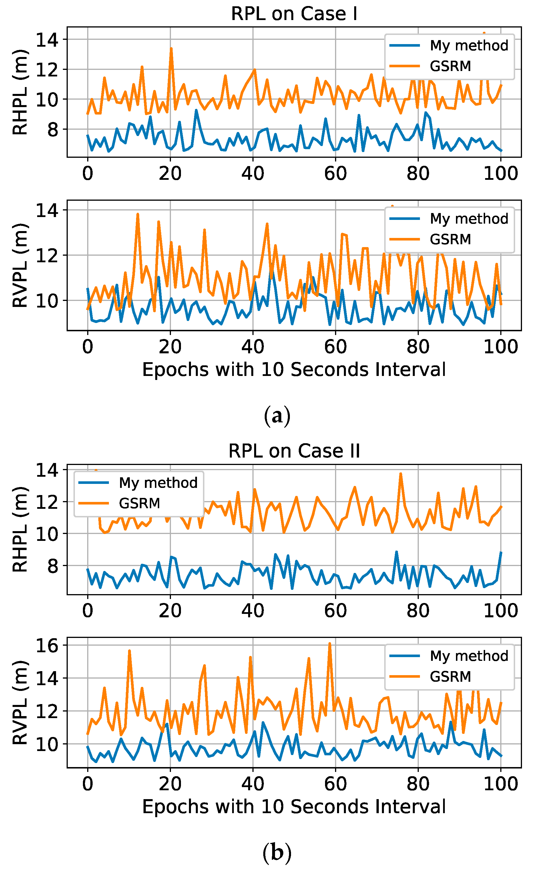
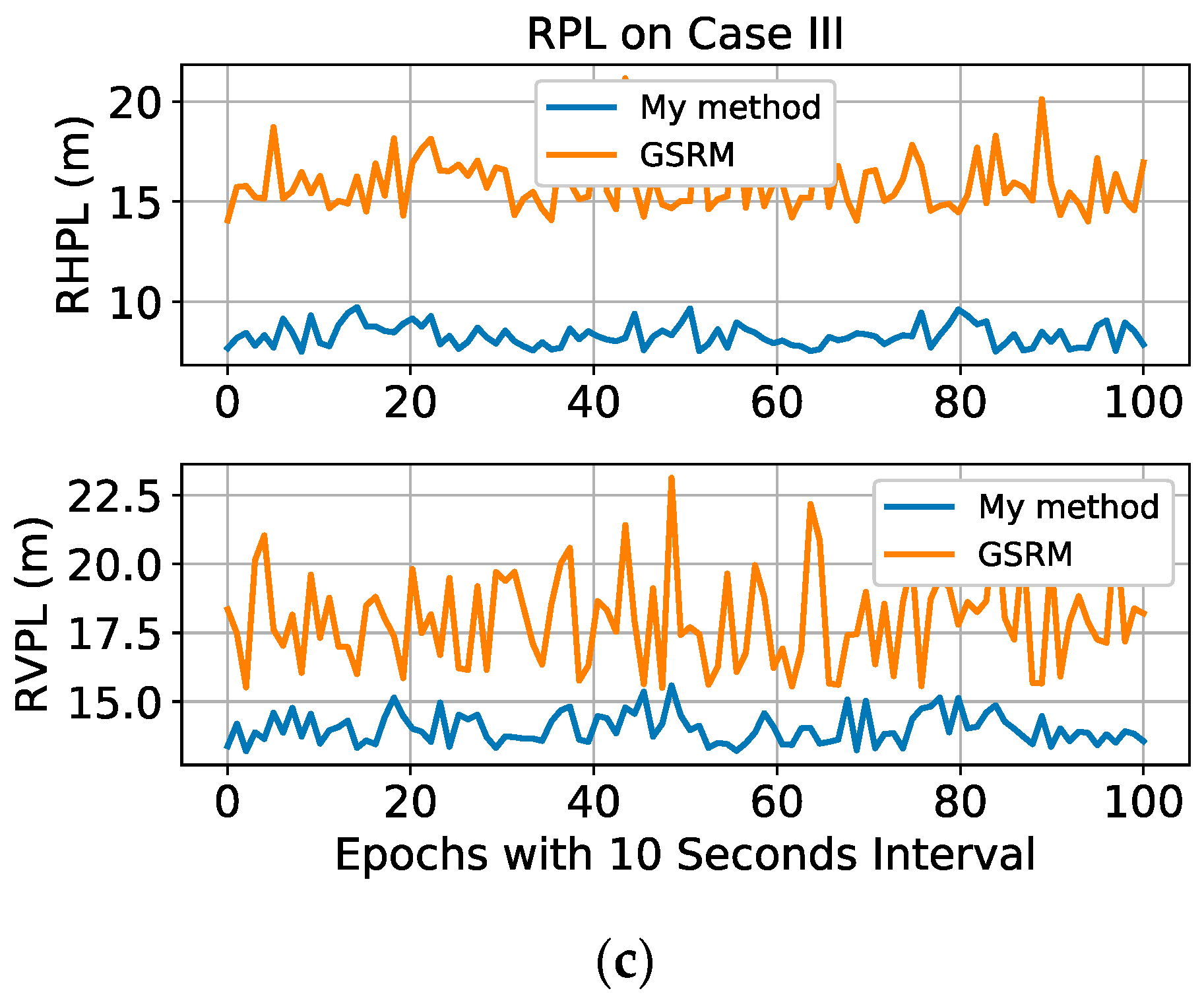
In the experiments, to test the relative navigation performance of multi-UAV systems, the RPL is estimated for relative position context. The experimental results show that a significant decrease in RPL is obtained by my method to improve the availability of the system, when compared with the GSRM. Figure 7 shows a comparison of my method and the GSRM in terms of RPL estimation in different cases. Specifically, the RHPL and the RVPL are estimated and compared separately. The average RPLs are also shown in Table 3. For example, the average RHPLs of my method are 7.30 m, 7.37 m, and 8.33 m in the three experimental cases, respectively, while the average RHPLs of the GSRM are 10.23 m, 11.26 m, and 15.90 m in the same cases, respectively. The results show that my method obtains a more significant RHPL decrease than the GSRM by 28.6%, 34.5%, and 47.6% in the three experimental cases, respectively. Similarly, my method achieves a larger decrease in RVPL than the GSRM by 12.2%, 18.6%, and 22.0% in the three experimental cases, respectively. My experimental results show that as the geometric distribution becomes worse in different cases, UWB provides a greater impact on the improvement of the RPL performance. Moreover, compared with RVPLs, the performance improvements in RHPL are more significant. One possible reason is that high-precision UWB observations have brought significant improvements to the geometric distribution in the horizontal direction. Although better RPL results are obtained by the proposed method, there is still no integrity indicator for multi-UAV systems. Thus, one cannot yet use RAL to evaluate the performance in practical applications. The work will be further researched in the future.
4. Conclusions
To improve the reliability of relative navigation for multi-UAV systems, a novel autonomous integrity monitoring method is proposed, which fuses double differenced GNSS pseudoranges and UWB ranging units to improve the performance on fault detection and exclusion while obtaining a smaller RPL. Results on different experimental cases show great potential for my method in multi-UAV applications. Specifically, compared to the conventional GRSM, my method achieves a fault detection rate increasing by 8–27%, a fault exclusion rate increasing by 6–42%, and a RPL decreasing by 12–47% under the experimental cases.
However, the limitation of the proposed method is that it does not make full use of all of the inter-UAV measurements in a multi-UAV system. Additionally, in contrast to the area of civil aviation, the integrity performance indicators for multiple UAVs have not been determined in practical applications. These works will be further investigated in the future.
Author Contributions
Y.S. implemented the algorithm, analyzed the data, performed the experiments and wrote the paper. All authors have read and agreed to the published version of the manuscript.
Funding
This research was funded by the National Natural Science Foundation of China grant number 61803037. And the APC was funded by the National Natural Science Foundation of China grant number 61803037.
Institutional Review Board Statement
Not applicable.
Informed Consent Statement
Not applicable.
Data Availability Statement
Data sharing is not applicable to this article due to privacy.
Acknowledgments
The presented research work is supported by the National Natural Science Foundation of China (61803037).
Conflicts of Interest
The author declares no conflict of interest.
References
- Pedro, D.; Matos-Carvalho, J.; Azevedo, F.; Sacoto-Martins, R.; Bernardo, L.; Campos, L.; Fonseca, J.; Mora, A. FFAU-framework for fully autonomous UAVs. Remote Sens. 2020, 12, 3533. [Google Scholar] [CrossRef]
- Gupta, L.; Jain, R.; Vaszkun, G. Survey of important issues in UAV communication networks. IEEE Commun. Surv. Tutor. 2015, 18, 1123–1152. [Google Scholar] [CrossRef] [Green Version]
- Medvedev, A.; Telnova, N.; Alekseenko, N.; Koshkarev, A.; Kuznetchenko, P.; Asmaryan, S.; Narykov, A. UAV-derived data application for environmental monitoring of the coastal area of Lake Sevan, Armenia with a changing water level. Remote Sens. 2020, 12, 3821. [Google Scholar] [CrossRef]
- Rosen, P.; Hensley, S.; Wheeler, K.; Sadowy, G.; Miller, T.; Shaffer, S.; Muellerschoen, R.; Jones, C.; Zebker, H.; Madsen, S. Uavsar: A new NASA airborne SAR system for science and technology research. In Proceedings of the 2006 IEEE Conference on Radar, Verona, NY, USA, 24–27 April 2006; pp. 1–8. [Google Scholar]
- Waibel, M.; Keays, B.; Augugliaro, F. Drone Shows: Creative Potential and Best Practices; ETH Zurich: Zurich, Switzerland, 2017. [Google Scholar]
- Rahman, S.; Kim, G.; Cho, Y.; Khan, A. Positioning of UAVs for throughput maximization in software-defined disaster area UAV communication networks. J. Commun. Netw. 2018, 20, 452–463. [Google Scholar] [CrossRef]
- Hoang, G.M.; Denis, B.; Härri, J.; Slock, D. Bayesian fusion of GNSS, ITS-G5 and IR–UWB data for robust cooperative vehicular localization. Compt. Rendus Phys. 2019, 20, 218–227. [Google Scholar] [CrossRef]
- Minetto, A.; Gurrieri, A.; Dovis, F. A cognitive particle filter for collaborative DGNSS positioning. IEEE Access 2020, 8, 194765–194779. [Google Scholar] [CrossRef]
- Ang, K.; Dong, X.; Liu, W.; Qin, G.; Lai, S.; Wang, K.; Wei, D.; Zhang, S.; Phang, S.K.; Chen, X.; et al. High-precision multi-UAV teaming for the first outdoor night show in Singapore. Unmanned Syst. 2018, 6, 39–65. [Google Scholar] [CrossRef]
- Sun, Y.; Fu, L. Real-time game theory based artificial potential field method for multiple unmanned aerial vehicles path planning. In Proceedings of the 2018 International Technical Meeting of The Institute of Navigation, Reston, VA, USA, 29 January–1 February 2018; pp. 521–528. [Google Scholar]
- Um, I.; Park, S.; Kim, H.; Kim, H. Configuring RTK-GPS architecture for system redundancy in multi-drone operations. IEEE Access 2020, 8, 76228–76242. [Google Scholar] [CrossRef]
- Vetrella, A.; Fasano, G.; Accardo, D.; Moccia, A. Differential GNSS and vision-based tracking to improve navigation performance in cooperative multi-UAV systems. Sensors 2016, 16, 2164. [Google Scholar] [CrossRef]
- Sun, R.; Zhang, W.; Zheng, J.; Ochieng, W. GNSS/INS Integration with integrity monitoring for UAV no-fly zone management. Remote Sens. 2020, 12, 524. [Google Scholar] [CrossRef] [Green Version]
- Sun, Y. RAIM-NET: A deep neural network for receiver autonomous integrity monitoring. Remote Sens. 2020, 12, 1503. [Google Scholar] [CrossRef]
- Fu, L.; Zhang, J.; Li, R.; Cao, X.; Wang, J. Vision-aided RAIM: A new method for GPS integrity monitoring in approach and landing phase. Sensors 2015, 15, 22854–22873. [Google Scholar] [CrossRef] [Green Version]
- Zabalegui, P.; De Miguel, G.; Pérez, A.; Mendizabal, J.; Goya, J.; Adin, I. A review of the evolution of the integrity methods applied in GNSS. IEEE Access 2020, 8, 45813–45824. [Google Scholar] [CrossRef]
- Bhattacharyya, S.; Gebre-Egziabher, D. Kalman filter–based RAIM for GNSS receivers. IEEE Trans. Aerosp. Electron. Syst. 2015, 51, 2444–2459. [Google Scholar] [CrossRef]
- Bhatti, U.I.; Ochieng, W.Y.; Feng, S. Integrity of an integrated GPS/INS System in the presence of slowly growing errors. Part I: A critical review. GPS Solut. 2007, 11, 173–181. [Google Scholar] [CrossRef]
- Brown, R.G. A baseline GPS RAIM scheme and a note on the equivalence of three RAIM methods. Navigation 1992, 39, 301–316. [Google Scholar] [CrossRef]
- Isik, O.K.; Hong, J.; Petrunin, I.; Tsourdos, A. Integrity analysis for GPS-based navigation of UAVs in urban environment. Robotics 2020, 9, 66. [Google Scholar] [CrossRef]
- Sun, Y.; Fu, L. Autonomous fault detection and exclusion for relative positioning of multiple moving platforms using carrier phase. In Proceedings of the 31st International Technical Meeting of the Satellite Division of The Institute of Navigation (ION GNSS+ 2018), Miami, FL, USA, 24–28 September 2018; pp. 1639–1646. [Google Scholar]
- Wang, S.; Zhan, X.; Zhai, Y.; Chi, C.; Shen, J. Highly reliable relative navigation for multi-UAV formation flight in urban environments. Chin. J. Aeronaut. 2020, in press. [Google Scholar] [CrossRef]
- Groves, P.D.; Offer, C.R.; Mather, C.J.; Pulford, G.W.; Ashokaraj, I.A.; Macaulay, A.A. Optimizing the algorithm design for high integrity relative navigation using carrier phase relative GPS integrated with INS. In Proceedings of the 21st International Technical Meeting of the Satellite Division of the Institute of Navigation (ION GNSS), 16–19 September 2008; pp. 1323–1334. [Google Scholar]
- Calhoun, S.M.; Raquet, J. Integrity determination for a vision based precision relative navigation system. In Proceedings of the 2016 IEEE/ION Position, Location and Navigation Symposium (PLANS), Savannah, GA, USA, 11–16 April 2016; pp. 294–304. [Google Scholar]
- Heredia, G.; Caballero, F.; Maza, I.; Merino, L.; Viguria, A.; Ollero, A. Multi-unmanned aerial vehicle (UAV) cooperative fault detection employing differential global positioning (DGPS), inertial and vision sensors. Sensors 2009, 9, 7566–7579. [Google Scholar] [CrossRef] [PubMed]
- Maaref, M.; Kassas, Z.M. UAV integrity monitoring measure improvement using terrestrial signals of opportunity. In Proceedings of the 32nd International Technical Meeting of the Satellite Division of The Institute of Navigation (ION GNSS+ 2019), Miami, FL, USA, 16–20 September 2019; pp. 3045–3056. [Google Scholar]
- Rife, J. Collaboration-enhanced receiver integrity monitoring with common residual estimation. In Proceedings of the IEEE/ION Position, Location and Navigation Symposium—PLANS, Myrtle Beach, SC, USA, 23–26 April 2012; pp. 1042–1053. [Google Scholar]
- Margaria, D.; Falletti, E. A novel local integrity concept for GNSS receivers in urban vehicular contexts. In Proceedings of the IEEE/ION Position, Location and Navigation Symposium—PLANS, Monterey, CA, USA, 5–8 May 2014; pp. 413–425. [Google Scholar]
- Ansari, K.; Feng, Y.; Tang, M. A runtime integrity monitoring framework for real-time relative positioning systems based on GPS and DSRC. IEEE Trans. Intell. Trans. Syst. 2014, 16, 980–992. [Google Scholar] [CrossRef] [Green Version]
- Xiong, J.; Cheong, J.; Xiong, Z.; Dempster, A.; Tian, S.; Wang, R. Integrity for multi-sensor cooperative positioning. IEEE Trans. Intell. Trans. Syst. 2021, 22, 792–807. [Google Scholar] [CrossRef]
- Gross, J.N.; Gu, Y.; Rhudy, M.B. Robust UAV relative navigation with DGPS, INS, and radio ranging. IEEE Trans. Autom. Sci. Eng. 2015, 12, 935–944. [Google Scholar] [CrossRef]
- Guo, K.; Qiu, Z.; Meng, W.; Xie, L.; Teo, R. Ultra-wideband based cooperative relative localization algorithm and experiments for multiple unmanned aerial vehicles in GPS denied environments. Int. J. Micro Air Veh. 2017, 9, 169–186. [Google Scholar] [CrossRef]
- Wang, S.; Almansa, C.M.; Queralta, J.P.; Zou, Z.; Westerlund, T. UWB-based localization for multi-UAV systems and collaborative heterogeneous multi-robot systems. Procedia Comput. Sci. 2020, 175, 357–364. [Google Scholar]
- Groves, P. Principles of GNSS, Inertial and Multi-Sensor Integrated Navigation Systems, 2nd ed.; Artech House Publishers: Norwood, MA, USA, 2013. [Google Scholar]
- Gerdan, G.P. A comparison of four methods of weighting double difference pseudorange measurements. Aust. Surv. 1995, 40, 60–66. [Google Scholar] [CrossRef]
- Chan, F.C.; Joerger, M.; Khanafseh, S.; Pervan, B. Bayesian fault-tolerant position estimator and integrity risk bound for GNSS navigation. J. Navig. 2014, 67, 753–775. [Google Scholar] [CrossRef] [Green Version]
- Brown, R. Global Positioning System: Theory and Applications; American Institute of Aeronautics and Astronautics: Washington, DC, USA, 1996; pp. 143–165. [Google Scholar]
- GNSS Evolutionary Architecture Study, GEAS Phase-I Panel Report; FAA: Washington, DC, USA, 2008.
- Sun, Y.; Zhang, J.; Xue, R. Leveraged fault identification method for receiver autonomous integrity monitoring. Chin. J. Aeronaut. 2015, 28, 1217–1225. [Google Scholar] [CrossRef] [Green Version]
- Jiang, Y.; Wang, J. A new approach to calculate the horizontal protection level. J. Navig. 2016, 69, 57–74. [Google Scholar] [CrossRef] [Green Version]
- Blanch, J.; Walter, T.; Enge, P.; Lee, Y.; Pervan, B.; Rippl, M.; Spletter, A. Advanced RAIM user algorithm description: Integrity support message processing, fault detection, exclusion, and protection level calculation. In Proceedings of the 25th International Technical Meeting of the Satellite Division of The Institute of Navigation (ION GNSS 2012), Nashville, TN, USA, 17–21 September 2012; pp. 2828–2849. [Google Scholar]
- Milner, C.; Ochieng, W. Weighted RAIM for APV: The ideal protection level. J. Navig. 2011, 64, 61–73. [Google Scholar] [CrossRef]
Figure 1.
The framework of the proposed integrity monitoring method for multi-unmanned aerial vehicle (UAV) relative navigation.
Figure 1.
The framework of the proposed integrity monitoring method for multi-unmanned aerial vehicle (UAV) relative navigation.

Figure 2.
The double differenced Global Navigation Satellite System (GNSS) pseudorange observations.
Figure 2.
The double differenced Global Navigation Satellite System (GNSS) pseudorange observations.

Figure 3.
Schematic diagram for different probability densities of a relative distance in case of presence (fault on one satellite) and absence (fault free) of faulty measurements.
Figure 3.
Schematic diagram for different probability densities of a relative distance in case of presence (fault on one satellite) and absence (fault free) of faulty measurements.

Figure 4.
Calculation of relative protection level (RPL) aggregated from the maximum slope value multiplied by the detection threshold (1st term) and the inverse of the cumulative error distribution (2nd term).
Figure 4.
Calculation of relative protection level (RPL) aggregated from the maximum slope value multiplied by the detection threshold (1st term) and the inverse of the cumulative error distribution (2nd term).

Figure 5.
The sky maps of visible satellites. In the polar coordinate, the polar diameter and the polar angle refer to the elevation angle and the azimuth angle, respectively. The blue bands represent the masks of satellite observations in different conditions, (a) Original observations; (b) 30° elevation mask; (c) 60° azimuth mask.

Figure 6.
The performance of fault detection and exclusion in three different cases, (a) Results of fault detection rate; (b) Results of fault exclusion rate.
Figure 6.
The performance of fault detection and exclusion in three different cases, (a) Results of fault detection rate; (b) Results of fault exclusion rate.

Figure 7.
The RPL results of my method and GSRM in three different cases. Specifically, the Relative Horizontal Protection Level (RHPL) and the Relative Vertical Protection Level (RVPL) are estimated and compared separately to test the performance of the proposed method, (a) RPL results in Case I; (b) RPL results in Case II; (c) RPL results in Case III.


Table 1.
Descriptions for the products in the experiments.
| Product Name | Description | Value |
|---|---|---|
| UAV | Maximum Flight Time Maximum Speed Control Range | 60 min 15 m/s 10,000 m |
| GPS Module | Single Point Positioning (RMSE) DGPS (RMSE) Dual Frequency RTK (RMSE) Raw Data Sampling Rate | 3 m 0.9 m 1 cm 10 Hz |
| UWB Module | Center Frequency Maximum Ranging Distance Ranging Accuracy (RMSE) Raw Data Sampling Rate | 4.3 GHz 100 m 10 cm 100 Hz |
Table 2.
Performance of my method and GPS stand-alone RAIM method (GSRM) on different fault bias and 99% Minimal Detectable Biases (MDBs), in different cases.
Table 2.
Performance of my method and GPS stand-alone RAIM method (GSRM) on different fault bias and 99% Minimal Detectable Biases (MDBs), in different cases.
| Detection Rate for 10 m Fault Bias | 99% MDBs | Exclusion Rate for 15 m Fault Bias | |||||||
|---|---|---|---|---|---|---|---|---|---|
| Case I | Case II | Case III | Case I | Case II | Case III | Case I | Case II | Case III | |
| My method | 100% | 99.37% | 98.71% | 5.95 m | 8.93 m | 10.42 m | 97.86% | 97.23% | 92.92% |
| GSRM | 91.48% | 82.14% | 70.93% | 12.4 m | 15.38 m | 16.86 m | 91.49% | 75.09% | 50.54% |
Table 3.
The average RPLs in different cases.
| Case I | Case II | Case III | ||||
|---|---|---|---|---|---|---|
| Avg. RHPL (m) | Avg. RVPL (m) | Avg. RHPL (m) | Avg. RVPL (m) | Avg. RHPL (m) | Avg. RVPL (m) | |
| My method | 7.30 | 9.68 | 7.37 | 9.75 | 8.33 | 14.03 |
| GSRM | 10.23 | 11.02 | 11.26 | 11.98 | 15.90 | 17.99 |
Publisher’s Note: MDPI stays neutral with regard to jurisdictional claims in published maps and institutional affiliations. |
© 2021 by the author. Licensee MDPI, Basel, Switzerland. This article is an open access article distributed under the terms and conditions of the Creative Commons Attribution (CC BY) license (https://creativecommons.org/licenses/by/4.0/).
Share and Cite
MDPI and ACS Style
Sun, Y. Autonomous Integrity Monitoring for Relative Navigation of Multiple Unmanned Aerial Vehicles. Remote Sens. 2021, 13, 1483. https://0-doi-org.brum.beds.ac.uk/10.3390/rs13081483
AMA Style
Sun Y. Autonomous Integrity Monitoring for Relative Navigation of Multiple Unmanned Aerial Vehicles. Remote Sensing. 2021; 13(8):1483. https://0-doi-org.brum.beds.ac.uk/10.3390/rs13081483
Chicago/Turabian StyleSun, Yuan. 2021. "Autonomous Integrity Monitoring for Relative Navigation of Multiple Unmanned Aerial Vehicles" Remote Sensing 13, no. 8: 1483. https://0-doi-org.brum.beds.ac.uk/10.3390/rs13081483
Note that from the first issue of 2016, this journal uses article numbers instead of page numbers. See further details here.