
Research on the Impact of BDS-2/3 Receiver ISB on LEO Satellite POD
by
 , , and
Xinglong Zhao
1,2, 
Shanshi Zhou
2,*,
Jianfeng Cao
3,
Junjun Yuan
2,4,
Ziqian Wu
5 and
Xiaogong Hu
2 1
Institute of Telecommunication and Navigation Satellites, China Academy of Space Technology, Beijing 100094, China
2
Shanghai Astronomical Observatory, Chinese Academy of Sciences, Shanghai 200030, China
3
Beijing Aerospace Control and Command Center, Beijing 100094, China
4
University of Chinese Academy of Sciences, Beijing 100049, China
5
The 54th Research Insitute of CETC, Shijiazhuang 050081, China
*
Author to whom correspondence should be addressed.
Remote Sens. 2022, 14(11), 2514; https://0-doi-org.brum.beds.ac.uk/10.3390/rs14112514
Submission received: 20 February 2022
/
Revised: 13 May 2022
/
Accepted: 22 May 2022
/
Published: 24 May 2022
(This article belongs to the Special Issue Space-Geodetic Techniques)
Abstract
:In recent years, the multi-GNSS positioning application is becoming more and more popular, same to the low Earth orbit (LEO) satellite precise orbit determination (POD) based on the onboard multi-GNSS measurements. The third-generation Beidou navigation satellite system (BDS-3) provides a new option to obtain the LEO satellite orbit solutions. However, the receiver intersystem bias (ISB) of different GNSS is unavoidable in multi-GNSS data processing. This paper’s main goal is absorption of the impact of the ISB between BDS-3 and BDS-2 on the LEO satellite POD. Taking GPS-based POD solutions for the reference orbit, this paper evaluates the orbit accuracy of BDS-2-based POD, BDS-3-based POD, BDS-2 and BDS-3 combined PODs with/without ISB. The BDS-3-based POD accuracy is 6.57 cm in the 3D direction, a 56% improvement over BDS-2-based POD. When the ISB between BDS-3 and BDS-2 is estimated, the BDS-2/3 combined POD accuracy of 5.37 cm in the 3D direction is better than that without ISB, which is a 64% improvement over BDS-2-based POD and 18% improvement over BDS-3-based POD. For GPS and BDS-2/3 combined POD, the GPS and BDS-3 joint POD solutions have the smallest RMS differences in overlapping consistency and smallest RMS differences compared to GPS-based POD. This study indicates that estimating the BDS-2/3 receiver ISB in BDS-2/3 joint POD could improve the orbit accuracy, and the GPS and BDS-3 joint POD solution is better than another combined POD. This paper will provide meaningful references for the LEO satellite multi-GNSS-based POD.
1. Introduction
At present, it is mainstream to use the onboard Global Positioning System (GPS) measurements to obtain precise orbit solutions for low Earth orbit (LEO) satellites and other spacecrafts [1,2,3,4,5,6,7,8]. In 2012, the Beidou regional navigation satellite system (BDS-2) was built to provide positioning, navigation and timing (PNT) services to Asia-Pacific users, which accelerated the application and investigation of LEO satellite BDS-based orbit determination. Fengyun-3 employed a Global navigation satellite system occultation sounder (GNOS) to collect BDS-2/GPS measurements and opened the door to LEO orbit determination based on BDS [9,10,11,12,13]. Li Min accomplished an 8.4-cm precision orbit solution using the onboard BDS-2 measurements for the Fengyun-3C satellite [14]. The LING QIAO satellite carried a space-borne BDS receiver, an experimental payload, to complete in-orbit positioning experiment [15]. The Luojia-1A satellite is a navigation signal augmentation experimental satellite obtained centimeter-level orbit overlap consistence [16] with onboard BDS observations. Some researchers studied the GPS/BDS-2 differential code bias estimation based on Fengyun-3C/3D onboard measurements [17,18,19]. Lu Cuixian estimated the phase center variation (PCV) of BDS-2/GPS satellites and used them to improve the orbit precision of the Fengyun-3C satellite [20].
In August 2020, the third-generation Beidou navigation satellite system (BDS-3) was accomplished to work for users worldwide, which promotes the investigation and application of a Global navigation satellite system (GNSS). Yang Yuanxi explained in detail BDS-3, including the architecture, time system, coordinate reference frame, signals and the planned services [21]. Li Liu introduced the BDS-3 and presented the innovative designs and usage of BDS-3 navigation messages broadcast [22]. Some researchers have assessed the SIS (signals in space) accuracy and service performance of BDS-3 [23,24,25]. Zhao Xinglong first assessed the quality of onboard B1I/B3I measurements from the Tianping-1B nanosatellite. The study results showed that a 4.57-cm precision orbit was solved only using the onboard BDS-3 B1I/B3I ionosphere-free combined measurements. It is noteworthy that the BDS-3 precise products of orbit and clock offset used in LEO POD (precise orbit determination) are from the separate dedicated BDS POD result enhanced by BDS-3 intersatellite link measurements [26].
Lu Mingquan elaborated the modulation techniques and the detailed signal structures of BDS-3. In order to achieve compatibility and interoperability with other GNSSs, the BDS-3 broadcast the B1C signal was applied to a new quadrature multiplexed binary offset carrier (QMBOC) (6, 1, 4/33) modulation in B1 band at the 1575.42 MHz carrier frequency [27]. Simultaneously, for the BDS-3 satellite, the B1I signal uploaded at 1561.098 MHz carrier frequency was kept to combine the BDS-3 B1C signal into a multicarrier constant envelope composite navigation signal in the B1 band, sharing one common transmitter chain. The BDS-3 B1I signal strongly coherent with the B1C signal should be specially processed to user receivers [28,29], not the same as the BDS-2 B1I signal.
More researchers have studied the ISBs (intersystem biases) of multi-GNSS [30,31,32,33,34]. Many researchers have indicated that the ISB is a receiver-type dependent [35,36]. Li Xingxing studied the four-system positioning model, pointing out that the code hardware delay is set to zero to eliminate the singularity between the receiver clock and code hardware delay; the other GNSS would estimate the related code hardware delay bias with respect to the GPS [37], and the corresponding phase ambiguity parameters would absorb the phase hardware delay bias for the phase measurement. Wang Ningbo assessed the quality of the GPS, Galileo and BDS-2/3 satellite broadcast group delay and found a systematic B1I-B3I TGD (time group delay) offset between BDS-2 and BDS-3 [38]. Zhang Yize and Jiao Guoqiang found a clock offset and TGD bias between BDS-2 and -3 [39,40,41]. The clock bias was similar to each receiver, while the B1I-B3I TGD bias depended on the receiver type. Jiao Guoqiang held the point of view that the clock offset and TGD bias should be regarded as the ISB (intersystem bias) of BDS-2/3 while solving the combined BDS-2/3 position solution. Some investigators studied the joint BDS-2/3 precise point positioning (PPP), whose precision would be approved by estimating the intersystem bias of BDS-2/3 [42,43,44,45]. And the joint BDS-2/3 precise time transfer also benefits from the intersystem bias [46].
In the background above, it is meaningful and necessary to investigate the effect of the signal difference of BDS-2/3 on LEO POD. This paper first analyses the reason for receiver ISB between BDS-2 and BDS-3 and gives the measurement equation. Then, this paper collects the Tianping-1B onboard GPS and BDS-2/3 measurements for the experiments of BDS-3-based POD and the multi-GNSS-based POD.
2. GNSS ISB
The Tianping-1B receiver could receive the dual-frequency code and phase measurements. This paper adopts the ionosphere-free (IF) measurements combined from dual-frequency measurements to correct the ionosphere delay. Therefore, for the onboard GPS and BDS IF measurements, the observation equation is as follows:
The superscripts G and C denote, respectively, the GPS and BDS; and denote, respectively, the IF code measurements and phase measurements; is the true distance from the receiver to the navigation satellite; denotes the receiver clock errors of GPS and BDS; denotes the navigation satellite clock error; and denotes the dual-frequency IF wavelength and ambiguity value and and denote the IF code and phase noise.
The different GNSS signals have different hardware delay biases of signal transmission in the receiver. In the data processing, the hardware delay bias would be assimilated by the receiver clock error. The receiver clock error estimated is expressed as follows:
The superscript dtr denotes the clock’s true error, and denotes the hardware delay bias of the signal transmission in the receiver. The superscript denotes the GNSS receiver clock error, which contains the clock’s true error and hardware delay bias .Therefore, the GPS and BDS receiver clock errors are expressed as follows:
The difference of and could be considered as the receiver ISB (intersystem bias) of GPS and BDS, recorded as BCG:
Meanwhile, it is worth noting that the magnitude of the hardware delay of the carrier phase measurements is very small, and the carrier phase hardware delay could be absorbed into the ambiguity value [37]. Therefore, the ISBs of multi-GNSS receiver code measurements only are studied in this paper.
In a general way, the method to deal with ISB is to set the hardware delay bias to zero. Equation (4) could be expressed as follows:
The receiver clock error of BDS could be expressed as follows:
Therefore, Equation (1) could be expressed as follow:
We find, both Equations (1) and (7) are equivalent to deal with ISB. Therefore, the method to estimate the GPS receiver clock error as one parameter, and to estimate the BDS receiver clock error is another parameter together, equivalent to the way to estimate the GPS receiver clock error as one parameter and estimate the BDS-related ISB as one parameter together. This paper would adopt the first method to deal with the ISBs.
With respect to the receiver, different components and modulations of the BDS-2/3 signal in the B1 band [27] would lead to different B1I hardware delay biases of BDS-2/3. Likewise, the B1I/B3I IF combination signals of BDS-2 and BDS-3 would have different hardware delay biases, and the receiver clock errors estimated of BDS-2 and BDS-3 are different, such as the next equation:
For the onboard BDS ionosphere-free (IF) measurements from the LEO satellite, the observation equation would be expressed as follows:
3. POD Strategy
In this paper, a Tianping-1B satellite orbit solution is solved to use the GFZ rapid products of GPS/BDS satellite orbit and clock corrections. The precision of GFZ rapid products is very important due to the LEO orbit precision. We analyzed the BDS and GPS satellite orbit precision provided by GFZ. Then, the dynamic model used and our POD experiment designment were introduced.
3.1. BDS/GPS Onboard Data and Products
The multi-GNSS receiver employed by Tianping-1B continually collects L1/L2 of GPS and B1I/B3I of the BDS-2/3 dual-frequency code and phase measurements [26]. The GPS L1 and L2 signals are from G01~G32, and the BDS-2/3 B1I and B3I signals are from C01~C32. Among BDS-2/3, C01~C05 are Geostationary Equatorial Orbit (GEO) satellites of BDS-2; C06~C10, C13 and C16 are Inclined GeoSynchronous Orbit (IGSO) satellites of BDS-2 and C11, C12 and C14 are Medium Earth Orbit (MEO) satellites of BDS-2. The rest of the BDS satellites are MEO satellites of BDS-3.
Generally, the LEO satellite precise orbit is solved by fixing the GPS/BDS precise products, both orbit and clock correction [7,14]. GPS/BDS precise products are obtained by a precise post-process based on the raw dual-frequency measurements from abundant global monitoring stations, such as L1/L2 for GPS [47]. The multi-GNSS rapid products of GFZ (Geo Forschungs Zentrum) adopt the B1I/B3I dual-frequency code and phase measurements from both BDS-3 and BDS-2, and the GFZ multi-GNSS rapid products treat the BDS-2 B1I/B3I signal the same as that of BDS-3 (ftp.gfz-potsdam.de/GNSS/products/mgex/READ-ME.txt, accessed on 18 February 2022). The orbit accuracy of GFZ rapid products is expressed in the SP3 file header (ftp://igs.ign.fr/pub/igs/igscb/data/format/SP3d.pdf, accessed on 18 February 2022). During the span of POD data processing, we calculated the orbit accuracy average values per BDS and GPS satellite used in the period of DOY 340-363 in 2019.
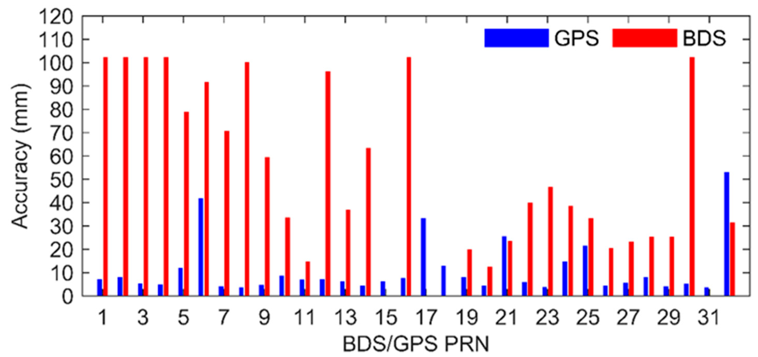
Figure 1 shows the BDS and each GPS satellite orbit accuracy means during DOY 340–363 in 2019. The orbit accuracy is from 35 cm to 100 cm for the BDS-2 satellites and less than 50 cm for all the BDS-3 satellites. The main GPS satellite orbit accuracy is less than 15 cm, except G06, G17, G21, G25 and G32.
3.2. POD Model
Table 1 expresses the measurement models, dynamic models and estimated parameters used in this study.
In this paper, the IF code and phase measurements are processed to solve the Tianping-1B orbit solutions with GFZ multi-GNSS rapid products. The a priori noise errors are 1 m for the IF code measurements and 1 cm for the IF phase measurements. The IF measurements eliminate the first-order ionospheric delay and neglect the higher-order delay. The GNSS antenna PCO (phase center offset) is from the igs14_2086.atx, and the Tianping-1B receiver antenna PCO is set to the nominal value (−0.087, 0.018, −0.23211) m [26]. The antenna PCVs of GNSS and receiver are neglected. The nominal attitude of Tianping-1B is a stable zero-yaw attitude mode (refer to [26]). The smallest elevation angle is set to 8°. The time span of POD arc is set to 30 h, and the interval of measurements is 10 s.
The dynamic models are adopted in the POD experiments, such as earth gravity of the 120 × 120 EIGEN_GL04C, N-body disturbance of DE421, relativistic effect, ocean tide of 10 × 10 FES 2004, solid earth and pole tide, solar radiation pressure of the Cannonball model, atmospheric drag of JB2008 and empirical forces.
The least squares algorithm is adopted to solve the unknown variable, such as the satellite initial state, the clock errors, ambiguity parameters and dynamic parameters. The clock errors are estimated per GNSS per epoch. The ambiguity parameter is set to one estimated value per arc per GNSS satellite without cycle slip. The coefficient of the Cannonball model is estimated by one parameter per POD arc. The coefficients of the JB2008 atmospheric drag model are estimated as one parameter per 1.5, and the sin and cos coefficients of the empirical force are estimated as one parameter per 3h in the along and cross directions.
In particular, the receiver ISB is the difference of the receiver clocks of the GPS and the other GNSS. In this paper, the receiver clock error is estimated as one value for GPS per epoch and another value for BDS-2, BDS-3 or BDS-2/3 per epoch, which is the same to estimate the receiver ISB [54].
3.3. Experiment Design
To study the POD potential of the onboard BDS measurements for the LEO satellite, we first solved the LEO satellite high-precision orbit based on the onboard GPS dual-frequency code and phase measurements. Taking the GPS-based POD results as the reference orbit, we evaluated the BDS-based POD results. The BDS-based POD experiments were divided into four parts. The first part was BDS-2-based POD, the second part was BDS-3 POD and the third part was denoted as BDS-2/3 POD, which treated BDS-2 and BDS-3 as one navigation system to solve the LEO satellite orbit. The final part denoted as BDS-2/3-B treated the BDS-2 and BDS-3 signals with different hardware delay biases in the onboard receivers, and BDS-2 and BDS-3 were treated as two navigation systems.
In addition, in order to analyze the performance of multi-GNSS-based POD, this paper preliminarily tried to obtain the orbit solutions of the different combined strategies from GPS, BDS-2 and BDS-3. GPS, BDS-2 and BDS-3 could be viewed as three separate systems for the onboard GNSS receiver. There are three combined POD solutions, the GPS+BDS-2-based POD solution, the GPS+BDS-3-based POD solution and the GPS+BDS-based POD solution. GPS and BDS-2 are treated as two system to solve the receiver ISB in the GPS+BDS-2-based POD solution, and the same thing was used with the GPS+BDS-3-based POD solution. In the GPS+BDS-based POD solution, GPS, BDS-2 and BDS-3 are treated as three systems to solve two ISBs.
4. Results and Analysis
For GPS-based POD orbit, the orbit overlapping consistency is adopted to evaluate the orbit accuracy. The BDS-based POD orbits accuracy is evaluated by comparison with GPS-based POD orbit, and the GPS/BDS-2/3 combined orbit solution is analyzed by the overlapping consistency and comparison with the GPS-based POD orbit.
4.1. GPS-Based Orbit
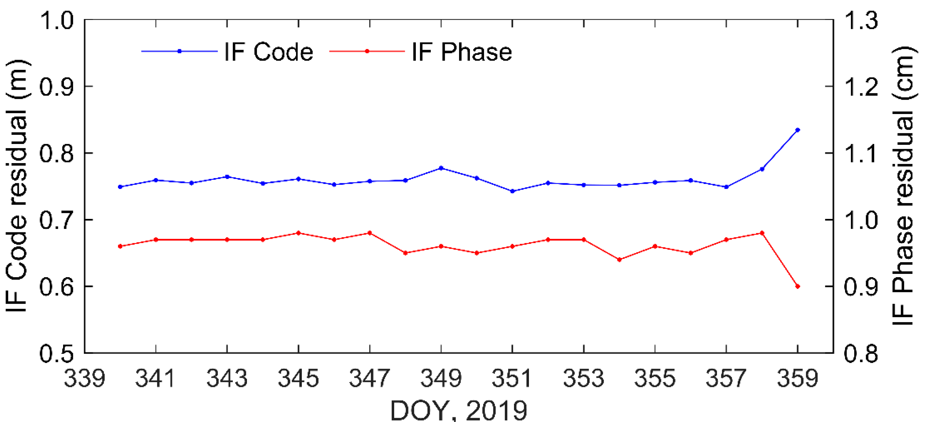
Figure 2 shows the GPS-based POD residuals of code pseudo-orange and the carrier phase measurements. The residual RMS value of the code pseudo-orange measurements is about 0.76 m, and the residual RMS value of the carrier phase measurement is about 0.96 cm.
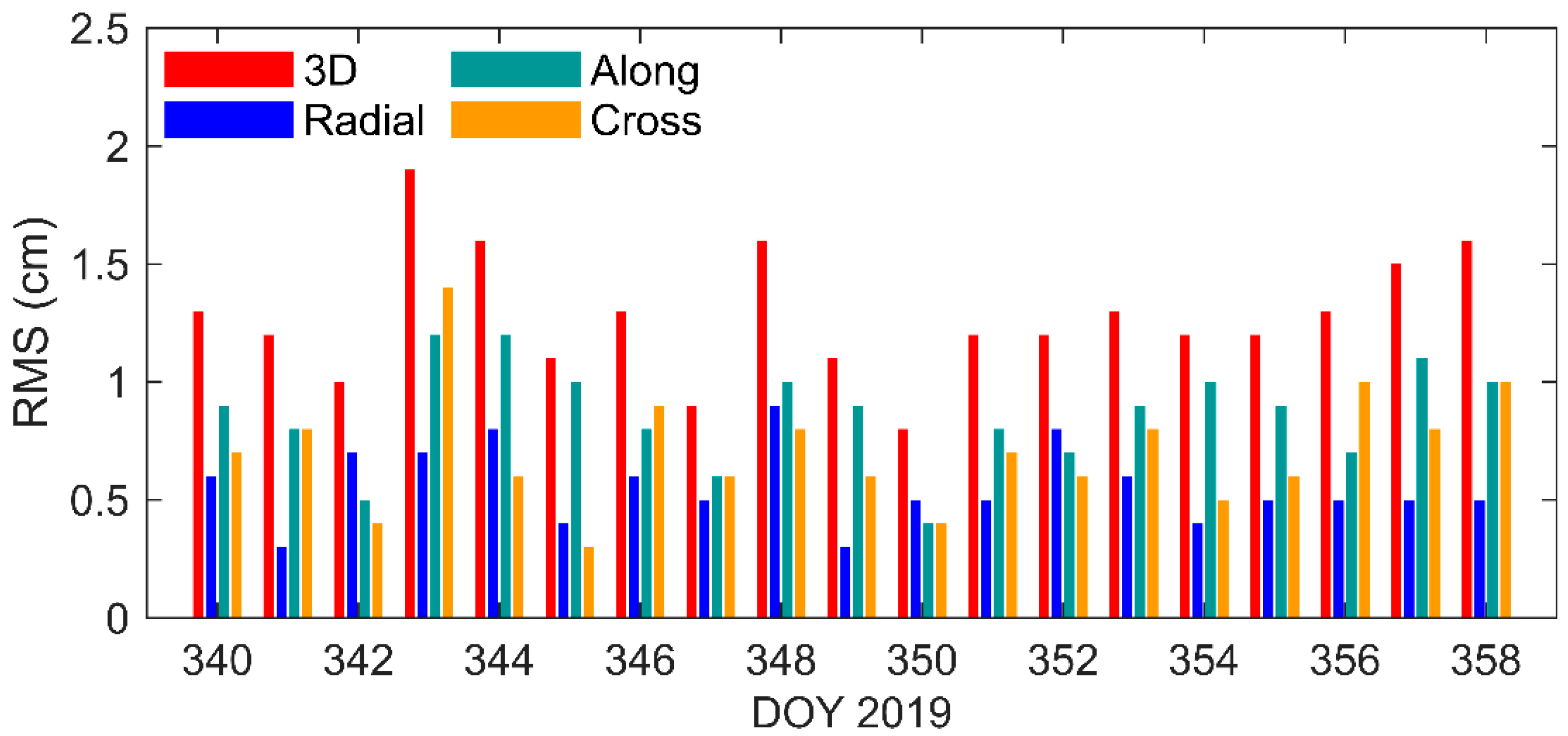
Figure 3 shows the RMS differences in overlapping consistency of the GPS-based orbits, and Table 2 shows the relevant statistical results. The overlap consistency 3D-RMS average is 1.28 cm, and the standard deviation is less than 0.3 cm. The 3D-RMS maximum value of the overlap consistency is 1.9 cm, and the minimum value of that is 0.8 cm. The radial overlap consistency average is 0.56 cm, and the standard deviation is less than 0.2 cm. The maximum and minimum values of that are, respectively, 0.9 cm and 0.3 cm. The average values of the along-track RMS and cross-track RMS are, respectively, 0.86 cm and 0.71 cm.
It can be seen that the 3D orbital overlap consistency of GPS-based POD is less than 2 cm, and the radial overlap consistency is less than 1 cm. Therefore, the GPS-based orbit solutions could be as a precision product to evaluate BDS-based orbit solutions.
4.2. BDS-3-Based POD
Using the spaceborne BDS-2/3 measurements and GFZ multi-GNSS rapid products, the Tianping1-B orbit is solved with different strategies, as described in Section 3.2.
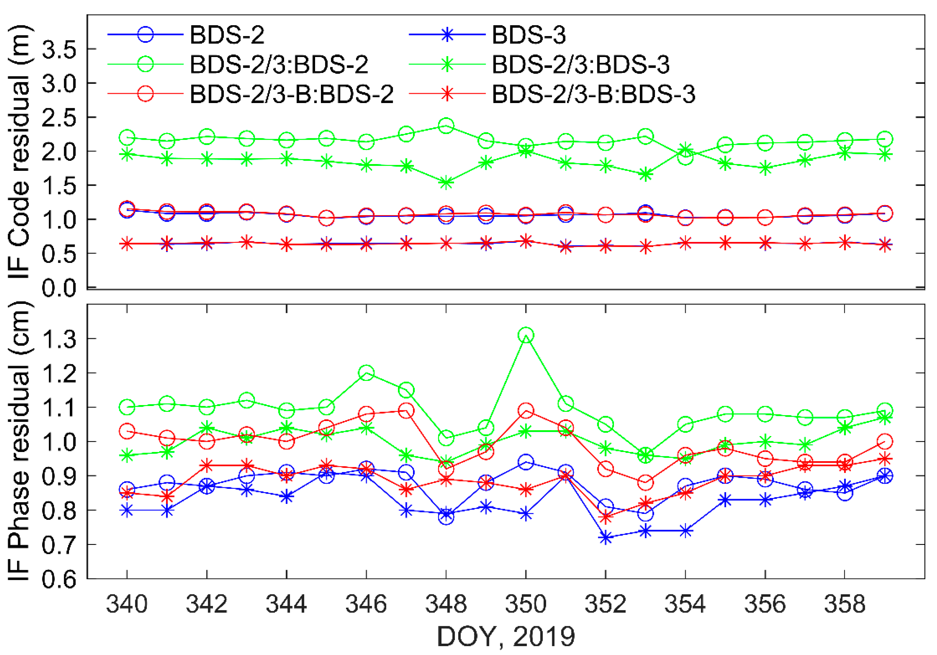
Figure 4 shows the BDS-based POD residuals with different strategies. For BDS-2-based POD, the IF code residual of BDS-2 is about 1.06 m, and the IF phase residual is about 0.88 cm. For BDS-3-based POD, the IF code and phase residuals are 0.64 m and 0.82 cm, respectively. For BDS-2/3-based POD, the IF code and phase residuals of BDS-2 are 2.16 m and 1.1 cm and that of BDS-3 are 1.85 m and 1.0 cm, respectively. Compared with BDS-2-based and BDS-2/3-based POD, the IF code and phase residuals of both BDS-2 and BDS-3 are larger. For BDS-2/3-B-based POD, the IF code and phase residuals of BDS-2 are 1.07 m and 0.99 cm and that of BDS-3 are 0.64 m and 0.89 cm, respectively. The IF code residual is equivalent to that of BDS-2-based and BDS-3-based POD compared with BDS-2/3-based POD.
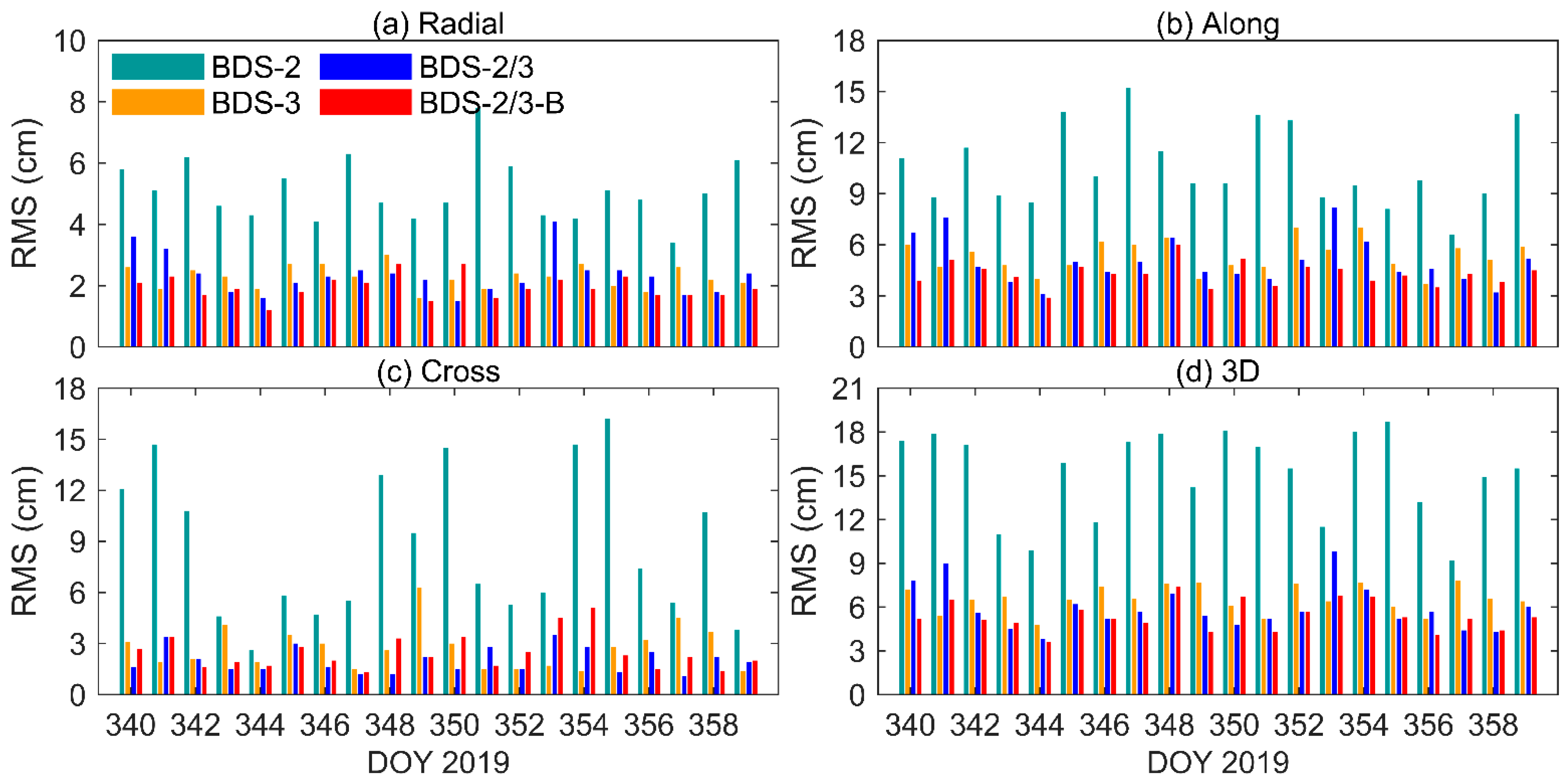
Figure 5 shows the BDS-based orbit RMS difference results compared with the GPS-based orbits, and the RMS difference statistics results are listed in Table 3. As illustrated in Table 3 and Figure 5, the BDS-3-based POD orbit 3D RMS difference is 6.57 cm and is reduced by 56% compared to BDS-2-based POD. This result indicates that the orbit accuracy of LEO POD based on BDS-3 has been greatly improved, compared with BDS-2-based POD.
For BDS-2 and BDS-3 combined POD, the BDS-2/3-B-based orbit 3D RMS difference of 5.37 cm is the lowest. It reduces 64% to be compared to the BDS-2-based orbit and 18% to be compared to the BDS-3-based orbit, which are significant compared to BDS-2/3-based POD. The orbit RMS difference between BDS-2/3-B-based POD and GPS-based POD is 1.96 cm in the radial direction, less than that of BDS-3-based POD and BDS-2/3-based POD. These results show that the receiver ISB estimated in the BDS-2 and BDS-3 combined POD could improve accuracy for the LEO satellite.
4.3. GPS+BDS-2/3 Combined Orbit Solution
Table 4 presents the IF code and phase residual statistics results of the GPS and BDS joint different strategies, as described in Section 3.2. The BDS-2 IF code and phase residuals are, respectively, about 115 cm and 1 cm for GPS+BDS-2-based POD solution and GPS+BDS-based POD solution. The BDS-3 IF code and phase residuals are, respectively, about 69 cm and 0.92 cm for GPS+BDS-3-based POD solution and GPS+BDS-based POD solution. The GPS IF code and phase residuals are, respectively, about 80 cm and 0.97 cm for each POD solution. These residuals results show that each system IF code residual from the three combined strategies is closed to the IF code residuals of the GPS-based, BDS-2-based and BDS-3-based POD.
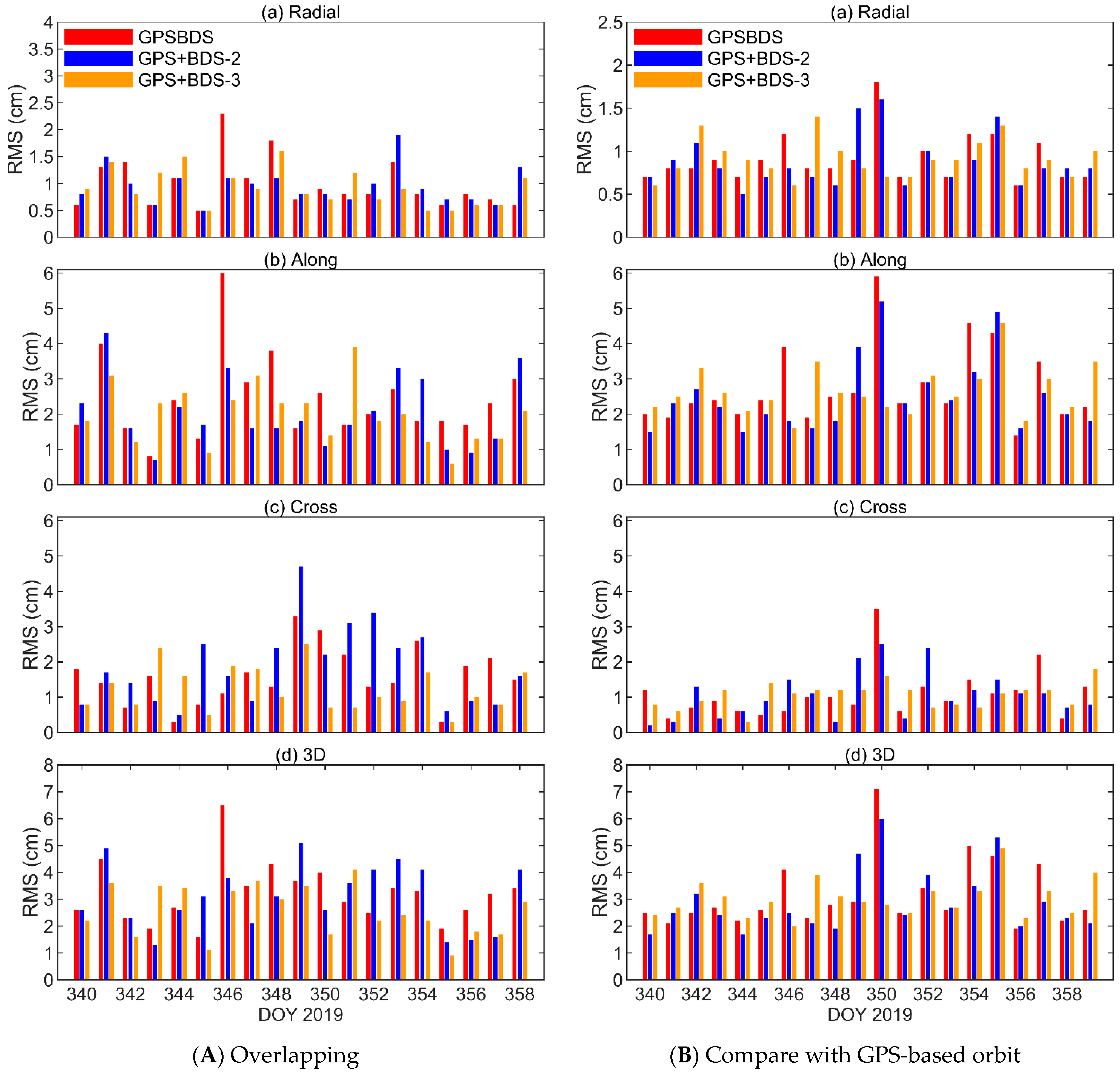
Figure 6 shows the results of both the orbit overlapping consistency and the combined orbit RMS errors compared with GPS-based POD, and Table 5 presents, respectively, the orbit RMS difference statistics. The 3D RMS differences for the orbit overlapping consistency are, respectively, 3.15 cm, 2.91 cm and 3.03 cm from the GPS+BDS-based POD solution, GPS+BDS-2-based POD solution and GPS+BDS-3-based POD solution, and the differences between them are less than 3 mm. The radial RMS differences for the orbit overlapping consistency of the three different strategies are, respectively, 0.91 cm, 0.88 cm and 0.91 cm, and the differences between them are less than 1 mm. The along and cross RMS differences for the orbit overlapping consistency of the three different strategies are, respectively, about 2.6 cm and 1.07 cm. It is important to note that the STD values of the GPS+BDS-3-based orbit overlapping consistency from all the POD arcs are smallest in the 3D, radial, along and cross directions.
The orbit RMS differences between the GPS+BDS-based POD solutions and GPS-based POD solutions are, respectively, 3.20 cm, 0.99 cm, 2.41 cm and 1.59 cm in the 3D, radial, along and cross directions. The GPS+BDS-2-based POD orbit RMS differences compared with the GPS-based orbit are, respectively, 3.07 cm, 0.95 cm, 2.06 cm and 1.85 cm in the 3D, radial, along and cross directions. The orbit RMS differences of the GPS and BDS-3 combined POD solutions and GPS-based POD are smaller than that of GPS+BDS-based and GPS+BDS-2-based POD and are, respectively, 2.57 cm, 0.92 cm, 1.98 cm and 1.24 cm in the 3D, radial, along and cross directions. It is also important to note that the STD values of all the POD orbit RMS differences between the GPS+BDS-3-based orbits and GPS-based orbits are the smallest in the 3D, radial, along and cross directions.
5. Conclusions
BDS-3 provides a new option for LEO POD and promotes the application of the multi-GNSS. It is unavoidable to estimate the GNSS receiver ISB in multi-GNSS applications. This paper preliminarily researched the impacts of GNSS receiver ISB for LEO POD in detail through the POD test with Tianping-1B onboard GPS and BDS data.
This paper discussed the reason for the ISB between BDS-2 and BDS-3 and gave the measurement equations. Using GFZ multi-GNSS rapid products, the ISBs were estimated in the Tianping-1B POD based on the BDS-2, BDS-3 and GPS measurements. Using only onboard BDS-3 measurements, the orbit accuracy was 6.57 cm in the 3D direction, improved by 56% from the BDS-2-based POD. When the ISBs of BDS-2 and BDS-3 were estimated in the combined POD, the orbit accuracy of 5.37 cm was 18% better than the BDS-3-based POD, which was nearly two times larger than the improvement ratio of the BDS-2/3-based POD with no ISB.
For the GPS and BDS combined POD, the orbit accuracy of GPS+BDS-3-based POD was higher. The 3D orbit RMS difference between the GPS+BDS-3-based POD solution and GPS-based POD solution was less than 3 cm, and its STD value was the smallest. These results illustrated that BDS-3 is more appropriate to join the GPS to determinate the LEO satellite orbit.
In conclusion, the ISB estimated between BDS-2 and BDS-3 could improve the Tianping-1B orbit accuracy using the onboard BDS-2/3 measurements. GPS and BDS-3 combined POD could obtain a more consistent orbit with a GPS-based orbit. It is meaningful to estimate the ISB to improve the Tianping-1B satellite orbit accuracy when using BDS-2 and BDS-3 measurements together. At the same time, the POD experiments with GPS and BDS provide an important reference for LEO POD with onboard multi-GNSS measurements.
Author Contributions
Conceptualization, X.Z. and X.H.; Formal analysis, X.Z.; Funding acquisition, S.Z.; Methodology, S.Z. and X.Z.; Resources, X.H.; Software, J.C. and Z.W.; Validation, S.Z.; Writing—original draft, X.Z. and S.Z. and Writing—review and editing, X.Z. and J.Y. All authors have read and agreed to the published version of the manuscript.
Funding
This research was funded by the National Natural Science Foundation of China (No. 12173072) and Qian Xuesen Youth Innovation Fund of China Aerospace Science and Technology Corporation In 2021.
Data Availability Statement
The Tianping-1B onboard GPS and BDS-3 data are supported by the Xi’an Satellite Control Center.
Acknowledgments
From the Xi’an Satellite Control Center, Guo Danni and Guo Kai are gratefully acknowledged for providing the onboard GPS and BDS-2/3 data from Tianping-1B. The authors thank GFZ for providing the multi-GNSS rapid products, and the authors are grateful to IGS for providing other necessary products. The authors thank the reviewers and editors for their constructive comments and words that have improved the quality of this manuscript.
Conflicts of Interest
The authors declare no conflict of interest.
References
- Montenbruck, O.; Hauschild, A.; Langley, R.B.; Siemes, C. CASSIOPE orbit and attitude determination using commercial off-the-shelf GPS receivers. GPS Solut. 2019, 23, 114. [Google Scholar] [CrossRef] [Green Version]
- Hauschild, A.; Montenbruck, O.; Langley, R.B. Flight results of GPS-based attitude determination for the Canadian CASSIOPE satellite. Navigation 2020, 67, 83–93. [Google Scholar] [CrossRef] [Green Version]
- Kahr, E.; Roth, N.; Montenbruck, O.; Risi, B.; Zee, R.E. GPS Relative Navigation for the CanX-4 and CanX-5 Formation-Flying Nanosatellites. J. Spacecr. Rocket. 2018, 55, 1–14. [Google Scholar] [CrossRef]
- Bock, H.; Jäggi, A.; Meyer, U.; Visser, P.; Ijssel, J.V.D.; van Helleputte, T.; Heinze, M.; Hugentobler, U. GPS-derived orbits for the GOCE satellite. J. Geod. 2011, 85, 807–818. [Google Scholar] [CrossRef] [Green Version]
- Hackel, S.; Gisinger, C.; Balss, U.; Wermuth, M.; Montenbruck, O. Long-Term Validation of TerraSAR-X and TanDEM-X Orbit Solutions with Laser and Radar Measurements. Remote Sens. 2018, 10, 762. [Google Scholar] [CrossRef] [Green Version]
- Montenbruck, O.; Hackel, S.; Ijssel, J.V.D.; Arnold, D. Reduced dynamic and kinematic precise orbit determination for the Swarm mission from 4 years of GPS tracking. GPS Solut. 2018, 22, 79. [Google Scholar] [CrossRef]
- Montenbruck, O.; Hackel, S.; Jaggi, A. Precise orbit determination of the Sentinel-3A altimetry satellite using ambiguity-fixed GPS carrier phase observations. J. Geod. 2018, 92, 711–726. [Google Scholar] [CrossRef] [Green Version]
- Guo, J.; Zhao, Q.; Guo, X.; Liu, X.; Liu, J.; Zhou, Q. Quality assessment of onboard GPS receiver and its combination with DORIS and SLR for Haiyang 2A precise orbit determination. Sci. China Earth Sci. 2015, 58, 138–150. [Google Scholar] [CrossRef]
- Xiong, C.; Lu, C.; Zhu, J.; Ding, H. Orbit determination using real tracking data from FY3C-GNOS. Adv. Space Res. 2017, 60, 543–556. [Google Scholar] [CrossRef]
- Cai, Y.; Bai, W.; Wang, X.; Sun, Y.; Du, Q.; Zhao, D.; Meng, X.; Liu, C.; Xia, J.; Wang, D.; et al. In-orbit performance of GNOS on-board FY3-C and the enhancements for FY3-D satellite. Adv. Space Res. 2017, 60, 2812–2821. [Google Scholar] [CrossRef]
- Zhao, Q.; Wang, C.; Guo, J.; Yang, G.; Liao, M.; Ma, H.; Liu, J. Enhanced orbit determination for BeiDou satellites with FengYun-3C onboard GNSS data. GPS Solut. 2017, 21, 1179–1190. [Google Scholar] [CrossRef] [Green Version]
- Li, X.; Zhang, K.; Zhang, Q.; Zhang, W.; Yuan, Y.; Li, X. Integrated Orbit Determination of FengYun-3C, BDS, and GPS Satellites. J. Geophys. Res. Solid Earth 2018, 123, 8143–8160. [Google Scholar] [CrossRef]
- Li, X.; Zhang, K.; Meng, X.; Zhang, Q.; Zhang, W.; Li, X.; Yuan, Y. LEO–BDS–GPS integrated precise orbit modeling using FengYun-3D, FengYun-3C onboard and ground observations. GPS Solut. 2020, 24, 48. [Google Scholar] [CrossRef]
- Li, M.; Li, W.; Shi, C.; Jiang, K.; Guo, X.; Dai, X.; Meng, X.; Yang, Z.; Yang, G.; Liao, M. Precise orbit determination of the Fengyun-3C satellite using onboard GPS and BDS observations. J. Geod. 2017, 91, 1313–1327. [Google Scholar] [CrossRef] [Green Version]
- Chen, X.; Zhao, S.; Wang, M.; Lu, M. Space-borne BDS receiver for LING QIAO satellite: Design, implementation and preliminary in-orbit experiment results. GPS Solut. 2016, 20, 837–847. [Google Scholar] [CrossRef] [Green Version]
- Wang, L.; Xu, B.; Fu, W.; Chen, R.; Li, T.; Han, Y.; Zhou, H. Centimeter-Level Precise Orbit Determination for the Luojia-1A Satellite Using BeiDou Observations. Remote Sens. 2020, 12, 2063. [Google Scholar] [CrossRef]
- Jiang, K.; Li, M.; Zhao, Q.; Li, W.; Guo, X. BeiDou Geostationary Satellite Code Bias Modeling Using Fengyun-3C Onboard Measurements. Sensors 2017, 17, 2460. [Google Scholar] [CrossRef] [Green Version]
- Li, W.; Li, M.; Shi, C.; Fang, R.; Zhao, Q.; Meng, X.; Yang, G.; Bai, W. GPS and BeiDou Differential Code Bias Estimation Using Fengyun-3C Satellite Onboard GNSS Observations. Remote Sens. 2017, 9, 1239. [Google Scholar] [CrossRef] [Green Version]
- Li, X.; Ma, T.; Xie, W.; Zhang, K.; Huang, J.; Ren, X. FY-3D and FY-3C onboard observations for differential code biases estimation. GPS Solut. 2019, 23, 57. [Google Scholar] [CrossRef]
- Lu, C.; Zhang, Q.; Zhang, K.; Zhu, Y.; Zhang, W. Improving LEO precise orbit determination with BDS PCV calibration. GPS Solut. 2019, 23, 109. [Google Scholar] [CrossRef]
- Yang, Y.; Gao, W.; Guo, S.; Mao, Y.; Yang, Y. Introduction to BeiDou-3 navigation satellite system. Navigation 2019, 66, 7–18. [Google Scholar] [CrossRef] [Green Version]
- Liu, L.; Zhang, T.; Zhou, S.; Hu, X.; Liu, X. Improved design of control segment in BDS-3. Navigation 2019, 66, 37–47. [Google Scholar] [CrossRef] [Green Version]
- Chen, J.; Hu, X.; Tang, C.; Zhou, S.; Yang, Y.; Pan, J.; Ren, H.; Ma, Y.; Tian, Q.; Wu, B.; et al. SIS accuracy and service performance of the BDS-3 basic system. Sci. China-Phys. Mech. Astron. 2020, 63, 269511. [Google Scholar] [CrossRef]
- Lv, Y.; Geng, T.; Zhao, Q.; Xie, X.; Zhou, R. Initial assessment of BDS-3 preliminary system signal-in-space range error. GPS Solut. 2019, 24, 16. [Google Scholar] [CrossRef]
- Yang, Y.; Mao, Y.; Sun, B. Basic performance and future developments of BeiDou global navigation satellite system. Satell. Navig. 2020, 1, 1. [Google Scholar] [CrossRef] [Green Version]
- Zhao, X.; Zhou, S.; Ci, Y.; Hu, X.; Cao, J.; Chang, Z.; Tang, C.; Guo, D.; Guo, K.; Liao, M. High-precision orbit determination for a LEO nanosatellite using BDS-3. GPS Solut. 2020, 24, 102. [Google Scholar] [CrossRef]
- Lu, M.; Li, W.; Yao, Z.; Cui, X. Overview of BDS III new signals. Navig. J. Inst. Navig. 2019, 66, 19–35. [Google Scholar] [CrossRef] [Green Version]
- Wang, C.; Cui, X.; Ma, T.; Zhao, S.; Lu, M. Asymmetric Dual-Band Tracking Technique for Optimal Joint Processing of BDS B1I and B1C Signals. Sensors 2017, 17, 2360. [Google Scholar] [CrossRef] [Green Version]
- Gao, Y.; Yao, Z.; Lu, M. A Coherent Processing Technique with High Precision for BDS B1I and B1C Signals. In China Satellite Navigation Conference; Springer: Singapore, 2020. [Google Scholar]
- Odijk, D.; Nadarajah, N.; Zaminpardaz, S.; Teunissen, P.J.G. GPS, Galileo, QZSS and IRNSS differential ISBs: Estimation and application. GPS Solut. 2017, 21, 439–450. [Google Scholar] [CrossRef]
- Teunissen, P. GNSS Precise Point Positioning. In Position, Navigation, and Timing Technologies in the 21st Century; Wiley: Hoboken, NJ, USA, 2021; Chapter 20; pp. 503–528. [Google Scholar]
- Tian, Y.; Yuan, L.; Tan, L.; Yan, H.; Xu, S. Regularization and particle filtering estimation of phase inter-system biases (ISB) and the lookup table for Galileo E1-GPS L1 phase ISB calibration. GPS Solut. 2019, 23, 115. [Google Scholar] [CrossRef]
- Mi, X.; Zhang, B.; Odolinski, R.; Yuan, Y. On the temperature sensitivity of multi-GNSS intra- and inter-system biases and the impact on RTK positioning. GPS Solut. 2020, 24, 112. [Google Scholar] [CrossRef]
- Pan, L.; Zhang, Z.; Yu, W.; Dai, W. Intersystem Bias in GPS, GLONASS, Galileo, BDS-3, and BDS-2 Integrated SPP: Characteristics and Performance Enhancement as a Priori Constraints. Remote Sens. 2021, 13, 4650. [Google Scholar] [CrossRef]
- Paziewski, J.; Wielgosz, P. Accounting for Galileo–GPS inter-system biases in precise satellite positioning. J. Geod. 2015, 89, 81–93. [Google Scholar] [CrossRef] [Green Version]
- Odijk, D.; Teunissen, P.J.G. Characterization of between-receiver GPS-Galileo inter-system biases and their effect on mixed ambiguity resolution. GPS Solut. 2013, 17, 521–533. [Google Scholar] [CrossRef]
- Li, X.; Zhang, X.; Ren, X.; Fritsche, M.; Wickert, J.; Schuh, H. Precise positioning with current multi-constellation Global Navigation Satellite Systems: GPS, GLONASS, Galileo and BeiDou. Sci. Rep. 2015, 5, 8328. [Google Scholar] [CrossRef] [PubMed]
- Wang, N.; Li, Z.; Montenbruck, O.; Tang, C. Quality assessment of GPS, Galileo and BeiDou-2/3 satellite broadcast group delays. Adv. Space Res. 2019, 64, 1764–1779. [Google Scholar] [CrossRef]
- Zhang, Y.; Kubo, N.; Chen, J.; Chu, F.-Y.; Wang, A.; Wang, J. Apparent clock and TGD biases between BDS-2 and BDS-3. GPS Solut. 2020, 24, 27. [Google Scholar] [CrossRef]
- Zhang, Y.; Wang, H.; Chen, J.; Wang, A.; Meng, L.; Wang, E. Calibration and Impact of BeiDou Satellite-Dependent Timing Group Delay Bias. Remote Sens. 2020, 12, 192. [Google Scholar] [CrossRef] [Green Version]
- Jiao, G.; Song, S.; Liu, Y.; Su, K.; Cheng, N.; Wang, S. Analysis and Assessment of BDS-2 and BDS-3 Broadcast Ephemeris: Accuracy, the Datum of Broadcast Clocks and Its Impact on Single Point Positioning. Remote Sens. 2020, 12, 2081. [Google Scholar] [CrossRef]
- Jiao, G.; Song, S.; Jiao, W. Improving BDS-2 and BDS-3 joint precise point positioning with time delay bias estimation. Meas. Sci. Technol. 2020, 31, 025001. [Google Scholar] [CrossRef]
- Zhao, W.; Chen, H.; Gao, Y.; Jiang, W.; Liu, X. Evaluation of Inter-System Bias between BDS-2 and BDS-3 Satellites and Its Impact on Precise Point Positioning. Remote Sens. 2020, 12, 2185. [Google Scholar] [CrossRef]
- Cao, X.; Shen, F.; Zhang, S.; Li, J. Time delay bias between the second and third generation of BeiDou Navigation Satellite System and its effect on precise point positioning. Measurement 2020, 168, 108346. [Google Scholar] [CrossRef]
- Song, Z.; Chen, J.; Wang, B.; Yu, C. (Eds.) Analysis and Modeling of the Inter-System Bias between BDS-2 and BDS-3; Springer: Singapore, 2020; p. 651. [Google Scholar]
- Qin, W.; Ge, Y.; Zhang, Z.; Su, H.; Wei, P.; Yang, X. Accounting BDS3–BDS2 inter-system biases for precise time transfer. Measurement 2020, 156, 107566. [Google Scholar] [CrossRef]
- Villiger, A.; Dach, R. (Eds.) International GNSS Service Technical Report 2019; IGS Annual Report; IGS Central Bureau and University of Bern; Bern Open Publishing: Bern, Switzerland, 2020. [Google Scholar]
- Flechtner, F.; Dahle, C.; Neumayer, K.H.; König, R.; Förste, C. The release 04 CHAMP and GRACE EIGEN gravity field models. In System Earth via Geodetic-Geophysical Space Techniques; Advanced Technologies in Earth Sciences; Springer: Berlin, Germany, 2010; pp. 1643–2190. [Google Scholar]
- Folkner, W.; Williams, J.; Boggs, D. The Planetary and Lunar Ephemeris DE 421; Interplanetary Network Progress Report; 42–178. Memorandum IOM 343R-08-003; Institute of Technology, Jet Propulsion Laboratory: Pasadena, CA, USA, 2009. [Google Scholar]
- Petit, G.; Luzum, B. IERS Conventions (2010); Technical Report; Verlag des Bundesamts fur Kartographie und Geodasie: Avignon, France; Frankfurt am Main, Germany, 2010. [Google Scholar]
- Lyard, F.; Lefevre, F.; Letellier, T.; Francis, O. Modelling the global ocean tides: Modern insights from FES2004. Ocean Dyn. 2006, 56, 394–415. [Google Scholar] [CrossRef]
- Rosengren, A.; Scheeres, D. Long-term dynamics of high area-tomass ratio objects in high-Earth orbit. Adv. Space Res. 2013, 52, 1545–1560. [Google Scholar] [CrossRef]
- Bowman, B.; Tobiska, W.K.; Marcos, F.; Huang, C.; Lin, C.; Burke, W. A new empirical thermospheric density model JB2008 using new solar and geomagnetic indices. In Proceedings of the AIAA/AAS Astrodynamics Specialist Conference and Exhibit, Honolulu, HI, USA, 18–21 August 2008. [Google Scholar]
- Choy, S.; Zhang, S.; Lahaye, F.; Héroux, P. A Comparison between GPS-only and Combined GPS+GLONASS Precise Point Positioning. J. Spat. Sci. 2013, 58, 169–190. [Google Scholar] [CrossRef]
Figure 1.
BDS and GPS satellite orbit accuracy.

Figure 2.
The GPS-based POD residuals.

Figure 3.
The RMS differences in the overlapping consistency of the GPS-based orbits.

Figure 4.
The BDS-based POD residuals with different strategies.

Figure 5.
The BDS-based orbit RMS errors results compared with the GPS-based orbits.

Figure 6.
The orbit RMS of the GPS and BDS combined different strategies. (A) The orbit RMS in overlapping consistency from GPS+BDS-based POD, GPS+BDS-2-based POD and GPS+BDS-3-based POD. (B)The orbit RMS between GPS-based POD and the three GPS and BDS combined POD strategies.
Figure 6.
The orbit RMS of the GPS and BDS combined different strategies. (A) The orbit RMS in overlapping consistency from GPS+BDS-based POD, GPS+BDS-2-based POD and GPS+BDS-3-based POD. (B)The orbit RMS between GPS-based POD and the three GPS and BDS combined POD strategies.


Table 1.
Measurement model, dynamic model and estimated parameters.
| Measurement Model | Models/Parameters |
|---|---|
| Observations | IF code measurements (1 m priori sigma), IF phase measurements (1 cm priori sigma) |
| GNSS precise products | GFZ multi-GNSS rapid products |
| Ionospheric delay | first-order delay eliminated, high orders neglected |
| GNSS phase center offset (PCO) | igs14_2086.atx |
| GNSS phase center variation (PCV) | Neglected |
| Tianping-1B PCO | Nominal value [26] |
| Tianping-1B PCV | Neglected |
| LEO attitude | Nominal model [26] |
| Smallest elevation angle | 8° |
| Time span/interval | 30 h, 10 s |
| Dynamics | Models/Parameters |
| Earth gravity model | EIGEN_GL04C, 120 × 120 [48] |
| N-body disturbance | DE421 [49] |
| Relativistic effect | IERS 2010 [50] |
| Earth orientation parameter | IERS 2010 [50] |
| Ocean tide | FES 2004, 10 × 10 [51] |
| Solid earth and pole tide | IERS 2010 [50] |
| Solar radiation pressure | Cannonball model [52] |
| Atmospheric drag | JB2008 [53] |
| Empirical force | Piecewise periodic estimation of sin and cos coefficients in along and cross directions and not in radial direction |
| Estimated parameters | Parameters |
| Tianping-1B initial state | Position and velocity at initial state |
| Receiver clock error | One value estimated per GNSS and per epoch |
| Ambiguities | One value per GNSS satellite per arc |
| Solar radiation pressure coefficients | One value per POD arc |
| Atmospheric drag coefficients | 1 per 1.5 h |
| Empirical force coefficients | 1 per 3.0 h |
Table 2.
The statistics of overlapping consistency of the GPS-based orbits (unit: cm).
| Statistics | 3D | Radial | Along | Cross |
|---|---|---|---|---|
| Max | 1.9 | 0.9 | 1.2 | 1.4 |
| Min | 0.8 | 0.3 | 0.4 | 0.3 |
| Mean | 1.28 | 0.56 | 0.86 | 0.71 |
| STD | 0.27 | 0.16 | 0.22 | 0.26 |
Table 3.
BDS-based orbit RMS difference statistics results compared with GPS-based orbits (unit: cm).
Table 3.
BDS-based orbit RMS difference statistics results compared with GPS-based orbits (unit: cm).
| Test | Reduced Ratio | 3D | Radial | Along | Cross | |
|---|---|---|---|---|---|---|
| BDS-2 | BDS-3 | |||||
| BDS-2-based POD | / | / | 15.10 | 5.11 | 10.56 | 8.69 |
| BDS-3-based POD | 56% | / | 6.57 | 2.29 | 5.36 | 2.74 |
| BDS-2/3-based POD | 61% | 10% | 5.92 | 2.35 | 5.02 | 2.02 |
| BDS-2/3-B-based POD | 64% | 18% | 5.37 | 1.96 | 4.28 | 2.48 |
Table 4.
The IF code and phase residual statistics results of the GPS and BDS joint different strategies (unit: cm).
Table 4.
The IF code and phase residual statistics results of the GPS and BDS joint different strategies (unit: cm).
| TEST | GPS+BDS-Based POD | GPS+BDS-3-Based POD | GPS+BDS-2-Based POD | |
|---|---|---|---|---|
| BDS-2 | IF code | 114.96 | \ | 115.02 |
| IF phase | 1.00 | \ | 1.00 | |
| BDS-3 | IF code | 68.14 | 69.03 | \ |
| IF phase | 0.91 | 0.93 | \ | |
| GPS | IF code | 79.68 | 80.42 | 79.30 |
| IF phase | 0.97 | 0.98 | 0.96 | |
| Entirety | IF code | 85.58 | 77.59 | 89.35 |
| IF phase | 0.96 | 0.97 | 0.97 | |
Table 5.
The orbit RMS difference statistics of the GPS and BDS combined different strategies (unit: cm).
Table 5.
The orbit RMS difference statistics of the GPS and BDS combined different strategies (unit: cm).
| Test | Statistic | Overlapping | Compared with GPS-Based Orbit | ||||||
|---|---|---|---|---|---|---|---|---|---|
| 3D | Radial | Along | Cross | 3D | Radial | Along | Cross | ||
| GPS+BDS-based POD | MEAN | 3.15 | 0.91 | 2.77 | 1.09 | 3.20 | 0.99 | 2.41 | 1.59 |
| STD | 1.25 | 0.27 | 1.09 | 0.70 | 1.13 | 0.47 | 1.19 | 0.81 | |
| GPS+BDS-2-based POD | MEAN | 2.91 | 0.88 | 2.51 | 1.07 | 3.07 | 0.95 | 2.06 | 1.85 |
| STD | 1.17 | 0.30 | 1.04 | 0.66 | 1.21 | 0.34 | 1.01 | 1.12 | |
| GPS+BDS-3-based POD | MEAN | 3.03 | 0.91 | 2.66 | 1.05 | 2.57 | 0.92 | 1.98 | 1.24 |
| STD | 0.68 | 0.22 | 0.69 | 0.34 | 0.95 | 0.34 | 0.84 | 0.63 | |
Publisher’s Note: MDPI stays neutral with regard to jurisdictional claims in published maps and institutional affiliations. |
© 2022 by the authors. Licensee MDPI, Basel, Switzerland. This article is an open access article distributed under the terms and conditions of the Creative Commons Attribution (CC BY) license (https://creativecommons.org/licenses/by/4.0/).
Share and Cite
MDPI and ACS Style
Zhao, X.; Zhou, S.; Cao, J.; Yuan, J.; Wu, Z.; Hu, X. Research on the Impact of BDS-2/3 Receiver ISB on LEO Satellite POD. Remote Sens. 2022, 14, 2514. https://0-doi-org.brum.beds.ac.uk/10.3390/rs14112514
AMA Style
Zhao X, Zhou S, Cao J, Yuan J, Wu Z, Hu X. Research on the Impact of BDS-2/3 Receiver ISB on LEO Satellite POD. Remote Sensing. 2022; 14(11):2514. https://0-doi-org.brum.beds.ac.uk/10.3390/rs14112514
Chicago/Turabian StyleZhao, Xinglong, Shanshi Zhou, Jianfeng Cao, Junjun Yuan, Ziqian Wu, and Xiaogong Hu. 2022. "Research on the Impact of BDS-2/3 Receiver ISB on LEO Satellite POD" Remote Sensing 14, no. 11: 2514. https://0-doi-org.brum.beds.ac.uk/10.3390/rs14112514
Note that from the first issue of 2016, this journal uses article numbers instead of page numbers. See further details here.