
Integration and Comparison Methods for Multitemporal Image-Based 2D Annotations in Linked 3D Building Documentation


Chair of Modelling and Simulation of Structures, Bauhaus-Universität Weimar, Marienstraße 13a, 99423 Weimar, Germany
*
Author to whom correspondence should be addressed.
Remote Sens. 2022, 14(9), 2286; https://0-doi-org.brum.beds.ac.uk/10.3390/rs14092286
Submission received: 31 March 2022
/
Revised: 5 May 2022
/
Accepted: 6 May 2022
/
Published: 9 May 2022
(This article belongs to the Special Issue Applications of Laser Scanning and Photogrammetry in Civil Engineering and Architecture: Beyond 3D Modeling)
Abstract
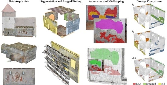
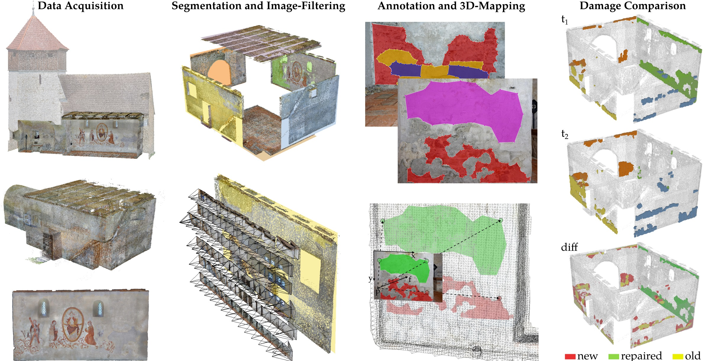
:Data acquisition systems and methods to capture high-resolution images or reconstruct 3D point clouds of existing structures are an effective way to document their as-is condition. These methods enable a detailed analysis of building surfaces, providing precise 3D representations. However, for the condition assessment and documentation, damages are mainly annotated in 2D representations, such as images, orthophotos, or technical drawings, which do not allow for the application of a 3D workflow or automated comparisons of multitemporal datasets. In the available software for building heritage data management and analysis, a wide range of annotation and evaluation functions are available, but they also lack integrated post-processing methods and systematic workflows. The article presents novel methods developed to facilitate such automated 3D workflows and validates them on a small historic church building in Thuringia, Germany. Post-processing steps using photogrammetric 3D reconstruction data along with imagery were implemented, which show the possibilities of integrating 2D annotations into 3D documentations. Further, the application of voxel-based methods on the dataset enables the evaluation of geometrical changes of multitemporal annotations in different states and the assignment to elements of scans or building models. The proposed workflow also highlights the potential of these methods for condition assessment and planning of restoration work, as well as the possibility to represent the analysis results in standardised building model formats.
1. Introduction
The conservation of historic buildings is an essential part of the preservation of cultural heritage. Therefore, ageing structures need to be inspected are regular intervals to counteract deterioration with a well-planned preservation strategy. As an outcome of a visual inspection that covers the entire interior and exterior building surface, damages and anomalies are documented by annotations in plans or in captured images. For a comprehensive dataset, this includes, on the one hand, the actual state and condition of a building and, on the other hand, the history of acquired data and performed evaluations in order to compare them to extract information on deformation or damage progression.
The field of data acquisition is increasingly supported by digital technology, such as image-based photogrammetric 3D reconstruction [1] or laser scanning, to obtain a highly detailed 3D dataset as a basis for condition assessment or planning of restoration works supported by automated processes. While Unmanned Aircraft Systems (UASs) are used to acquire images of façades of high and hard to reach building regions [2,3], this approach is rather used to capture indoor or outdoor areas of low building heights, where the UAS flight has technical limitations. Unlike laser scanning data, the photogrammetric reconstruction process estimates a camera position and orientation, the so-called extrinsic parameters, for each image along with the point cloud that is georeferenced by Ground Control Points (GCPs). This registration enables a location-based filtering of the image dataset and the mapping of information from the image plane onto a 3D surface [4,5,6]. Additionally, by triangulating such point clouds, surface meshes are derived [3,7]. The colour information stored for the point cloud as a defined colour value is stored as a texture from the image data on the mesh. The general result of this process is a detailed geometrical 3D representation of the captured building.
However, the essence of 3D methods in the field of data acquisition is usually not transferred to methods of damage assessment. There, due to a more familiar manual labelling of 2D information [8,9], the focus is on 2D data, such as drawings from Computer-Aided Design (CAD) systems, rectified images, orthophotos, or the raw image data. Furthermore, the automated labelling of image datasets by image segmentation employing deep learning techniques produces 2D information in the first place [10,11,12].
A transformation of 2D annotations to 3D geometries is thus necessary for 3D methods to be applied on the annotation data, such as integration in Geographic Information Systems (GISs), the extraction of damage dimensions through accurate measurements, or the evaluation of affected building elements [13]. In Grilli et al. (2018) [5] and Adamopoulos and Rinaudo (2021) [14], a workflow for the mapping of image segmentation labels onto 3D point clouds was proposed to transfer annotations from images and orthophotos to a semantically enriched point cloud. A forward- and back-projection of annotations to registered images from a photogrammetric reconstruction process that allows for the inclusion of additional imagery was described in Manuel et al. (2014) [4]. In there, the estimated camera positions were used to project an image-based annotation onto a building surface and to identify images that contain the same 3D annotation. Other inspection systems support direct 3D annotations along with high-performing web-based visualisation and an underlying database for the inspection of the data [6,9]. Furthermore, in Malinverni et al. (2019) [15], a building information model edited in a CAD system was used to apply a 3D annotation workflow with the goal of quantity determination and further planning.
The re-modelling of acquired 3D point clouds or meshes to achieve simplified building geometries is an important step towards the semantic enrichment of the dataset, and it is widely applied in the field of Historic (or Heritage) Building Information Modelling (HBIM) [15,16,17,18,19]. Depending on the targeted level of detail, the re-modelling process includes geometries from the definition of rough building sections as bounding boxes up to detailed volumetric building element models. A previous segmentation of the point cloud according to derived spatial criteria to identify building elements could support this process, as shown in Croce et al. (2021) [20]. Furthermore, a segmentation using deep learning techniques [21] or voxel-based methods [22,23], as well as the derivation of building geometries [24] enables the automated transformation of point clouds into semantically enriched and simplified models.
Inspection data that are acquired periodically from the same object in addition allow for the comparison of different states. Chiabrando et al. (2017) [25] applied such multitemporal comparative processing to identify post-earthquake damages of a church building in point cloud datasets of different states. Another example can be found from the identification of significant structural deformation of bridge piers due to temperature effects presented in Hallermann et al. (2018) [26]. In Vetrivel et al. (2016) [27], a voxel-based method for the comparison of pre- and post-earthquake point clouds led to the identification of damaged areas. The application of voxel-based methods enables the development of algorithms that are not based on a specific type of geometry, as also shown for typology analysis in Borrmann and Rank (2009) [28]. However, these studies investigated the identification of damages or deformation in multitemporal datasets, but did not compare the damage entities themselves. Three-dimensional annotations, as shown in the literature, independent of the identification method (e.g., manual, image, or point cloud segmentation) from different states, geometrically serve as a basis to identify localised changes of decays and possibly a derivation of damage progression.
This article proposes a methodological workflow for the integration of image-based 2D annotations into semantically enriched 3D models. Additionally, the obtained 3D annotations are assigned to the building elements to create a linked 3D dataset that serves as a basis for condition state evaluations. Finally, this process is repeated for three different annotated states, where the annotations of each state are assigned to each other to obtain a state history. The assigned annotation states are then compared, and a localised geometric change is extracted to evaluate the dimension of their increase over the compared states.
The article is structured as follows: Section 2.1 describes the background of the building, data acquisition, and first processing steps to reconstruct the 3D data, as well as the workflow. In Section 2.3, important data characteristics used in the workflow and additional modelling tasks, such as the definition of building sections, are explained. Methods of the integration of 2D annotations into 3D models and the application of assignment methods for the linking of 3D annotations, building elements, and different states are explained in detail in Section 2.4. Finally, the resulting linked dataset and the computed state comparisons for the extraction of local damage increases are presented in Section 3.
2. Materials and Methods
2.1. Case Study
The observed structure, the early Gothic church building of the Wehrkirche Döblitz, is located in Germany, in the federal state Thuringia, in a region called Vogtland. The Wehrkirche Döblitz is a so-called fortified church constructed in the 13th Century. As part of a research project, where several cultural heritage buildings in the region Vogtland were conserved as digital models, the church was captured with RGB images (exterior surface by uas, main hall and sanctuary manually) and laser scanning (attic). Besides the thick historic brick walls and the wooden roof, a wall painting is placed at the inside of the main hall. The wall painting was uncovered during restoration works in 1965. The interior surfaces of the walls have a highly decayed plaster layer, which was locally patched.
In this case study, solely the main hall was examined by the automated generation and evaluation of an image-based 3D damage mapping from manual 2D annotations. It is the goal to build a linked dataset to identify, quantify, and locate damages and damage increases for further planning of restoration works. Figure 1 shows the reconstructed point cloud of the exterior surface, the interior (main hall and sanctuary including the wall painting), along with the corresponding orthophoto of the wall painting.
As the dataset contains only a single state of the building, which is not sufficient to apply a state comparison, the 2D annotations for two previous states were generated synthetically on the captured images. Nevertheless, the characteristics and formats of the annotations are comparable to those of a multitemporal dataset. The investigations are intended to propose automated processing methods for questions of building maintenance, such as:
- Which point cloud section belongs to a specific building element?
- Which images contain parts of a specific building element?
- How are 2D annotations transferred to 3D geometries?
- Is a specific building element affected by annotations and by which?
- Which annotation was already part of a previously processed dataset?
- Where and of what dimension are the geometrical changes of the annotations compared to previous datasets?
- What amount of deterioration from this comparison was detected on a specific building element?
2.2. Methodological Approach
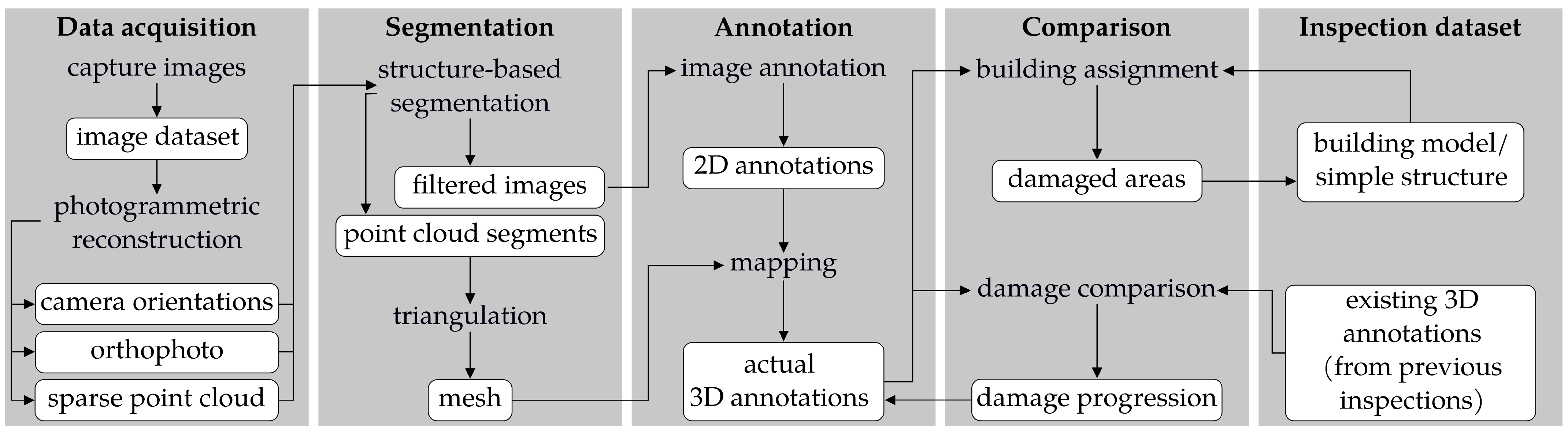
The workflow presented in this case study aims to process the acquired data into a linked 3D dataset. For this purpose, image-based 2D annotations of each data acquisition campaign were mapped to the reconstructed building surface. This enables the resulting 3D geometries to be assigned to the corresponding building elements and the images containing the damage. In a next step, the multitemporal annotations were assigned to those annotations that represent the same damage in a previous state. Based on the assignment, the local damage differences between the states were evaluated. The information from all these steps were integrated into a linked inspection dataset that allows queries and serves as a basis for further analyses or documentation. Figure 2 shows the processing workflow for the actual dataset for each state, including the comparison to previous inspections. The steps of data acquisition and segmentation are explained in Section 2.3 and the processes of annotation and comparison in Section 2.4.
2.3. Dataset
The dataset used consists of three parts, which will be acquired for each inspection: (1) the captured georeferenced image dataset and the corresponding 3D reconstructions and orthophotos, (2) the manually defined building elements of the main hall, and (3) the annotations of the visible damages on the images. For the georeferencing of the image data, GCPs were distributed on the building surface and in the surroundings (10 outside, 6 inside), which were considered in the photogrammetric 3D reconstruction process using Structure from Motion (SfM) [1] in the software Agisoft Metashape.
2.3.1. Images and Point Cloud
In total, the dataset of the main hall from the image acquisition and reconstruction process includes:
- A collection of 1881 images ( ) captured with a mean distance of ( for the wall painting);
- A sparse point cloud with from the photogrammetric reconstruction (approximately /);
- The estimated extrinsic parameters of the camera for each image (see Figure 3);
- A computed orthophoto of the wall painting with a size of approximately 36 and a resolution of / (see Figure 1).
Besides the camera orientations, the reconstruction process also results in the correspondences between the 3D position of each point of the sparse point cloud and the pixel position in the respective images. Consequently, it is known which subset of the sparse point cloud is contained in which specific images. These correspondences are stored in a so-called bundler file [29].
2.3.2. Structured Segmentation
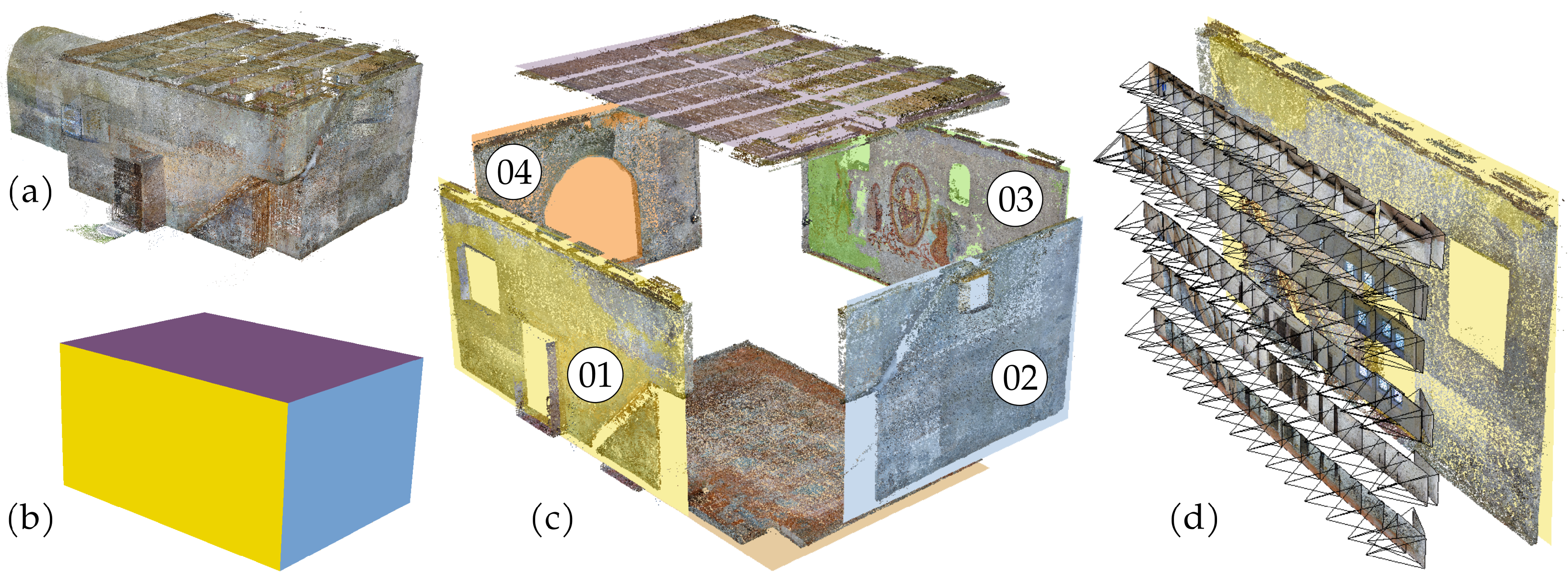
The dataset of the images and point cloud is unstructured at this point and, thus, needs a semantic segmentation to arrange the data for more effective processing, as also presented in Apollonio et al. (2018) [9]. Therefore, a simplified model of the main hall, representing the floor, walls, and roof as facets, was manually modelled. As shown in Figure 3, the facets were used to apply a segmentation of the point cloud to solely include:
- Points within a user-defined distance threshold of 20 ;
- Images with a corresponding camera direction of view with an angle of no greater than 20 to the facet normal.
The resulting segments contain a point and image subset related to each of the manually defined facets. The definition of the angle parameter favours the mapping of imagebased annotations, as described in Section 2.4.1.
In Poux and Billen (2019) [23], a method for the detection of planar clusters and the segmentation of point clouds using voxel grids was proposed. This method removes the necessity of manual facet modelling to an automated extraction of simplified building element geometries. As this case study is not focused on the geometry extraction from point clouds, but on the comparison of annotations, this part of the process is kept as simple manual modelling. However, the actual segmentation of the point cloud and image dataset based on pre-defined building element geometries was implemented as an automated process. Consequently, the proposed segmentation allows for an application to other captured states of the same structure, as long as the reconstruction is georeferenced.
2.3.3. Annotations
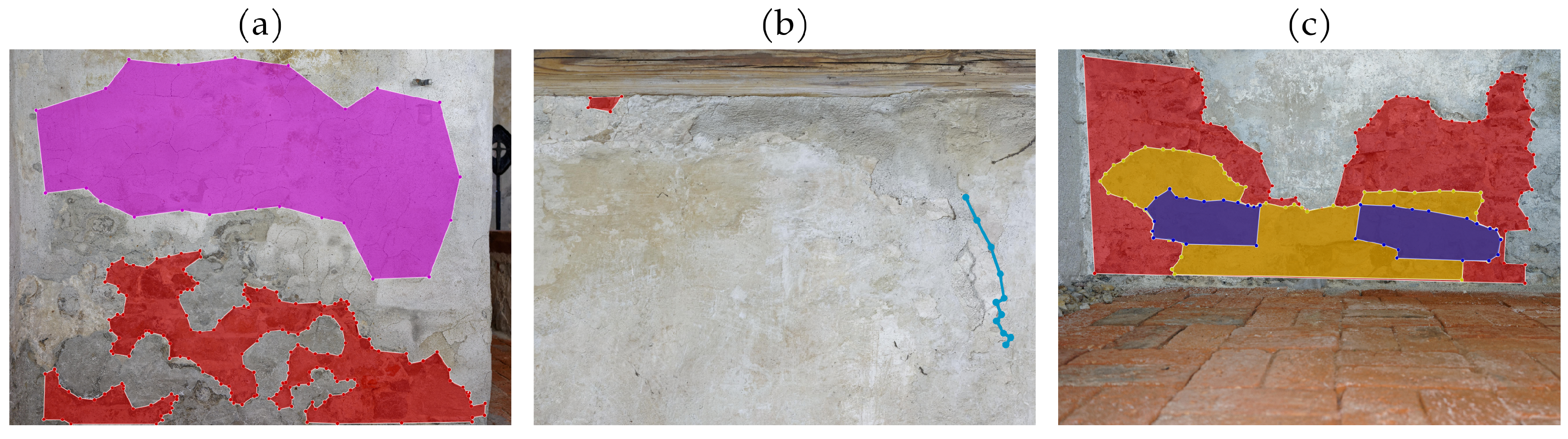
The image dataset was annotated in the open-source software labelme [30] to create a collection of damage annotations. Due to the previous segmentation, the images (JPG file format) were already grouped by building element and filtered by view direction in order to obtain an optimised basis for an effective annotation. For Wall 03 (with wall painting), the computed orthophoto in the commonly used file format TIFF was used. To separate the high-resolution orthophoto into manageable partitions, a raster segmentation into equally sized patches was applied. Figure 4 shows three examples of annotated images from labelme with cracks, craqueles, and missing plaster and the annotations for different states.
In total, 65 damages in three different states, assigned to four categories, were annotated as a polyline along the crack centreline or as a polygon around the affected area for craqueles, discolourations, and missing plaster.
For the multitemporal datasets, this annotation process was repeated for each state. To synthetically generate three different states of deterioration in this case study (with only a single state being captured), smaller polygons or polylines in a typical position were created on top of the original annotations. Thus, a dataset for two additional synthetic states with increasing decay was simulated. In the case of the wall painting, areas of missing plaster were already repaired. In order to consider restoration, these annotations were not assigned to the latest state and should be identified as repaired damages in the automated analysis process.
2.4. Methods
For the case study, the segmentation, mapping, assignment, and comparison processes presented in the workflow in Section 2.2 were implemented by the authors in the programming language JAVA. All 3D data entities were kept in simple and open formats to use a broad range of visualisation software and processing libraries. Compared to proprietary data formats, which are deployed in or part of specialised software, the data are not dependent on software updates or feature deprecation and, thus, appropriate for a long-time interpretable digital documentation. A more detailed description of the data management in this case study is provided in Section 2.4.5.
2.4.1. Mapping of 2D Annotations
As a first step towards a 3D comparison of multitemporal damage annotations, the image-based 2D annotations need to be transferred to 3D geometries. In this case study, the mapping process is composed of the following steps:
- 1
- Triangulation of the segmented part of the sparse point cloud to generate a target for the ray casting;
- 2
- Mapping of vertices of a polygon or polyline on the surface in the view direction (and in the case of the polygons, triangulation to a surface);
- 3
- Storage of the resulting 3D information including characteristic dimensions (e.g., crack length, discoloured area, or spalling volume), the bounding box, and the annotation semantic.
The triangulation of the sparse point cloud is performed as a precondition for the following ray casting. Therefore, a Poisson surface reconstruction [31] was applied with a , producing a triangle mesh over the reconstructed building element surface. In the following, this mesh is used as target geometry for the ray casting of 2D image information.
The ray casting itself uses the extrinsic and intrinsic camera parameters from the photogrammetric reconstruction for the mapping from 2D image information to global 3D coordinates. At this point, it is important to distinguish between the original camera images and computed orthophotos. For the original images, a pinhole camera model was assumed. Additionally, two coefficients for radial lens distortion, and (part of the bundler file [29], as well as the focal length f) were considered. The farther a pixel is from the centre of an image in the acquired dataset, the higher the influence of this distortion on the ray casting is. Figure 5 shows an exemplary mapping of an image-based annotation in the case study.
In contrast to the aforementioned image-based central projection, an orthogonal projection from the image plane was conducted for the mapping of annotations from orthophotos. Effects such as distortions are already compensated by the photogrammetric reconstruction and do not need to be considered. The global coordinate of the image origin and the global direction vectors for ordinate and abscissa vectors of the image coordinate system are the necessary information. This allows registering the orthophoto on the 3D scene and mapping the annotations to the building element surfaces.
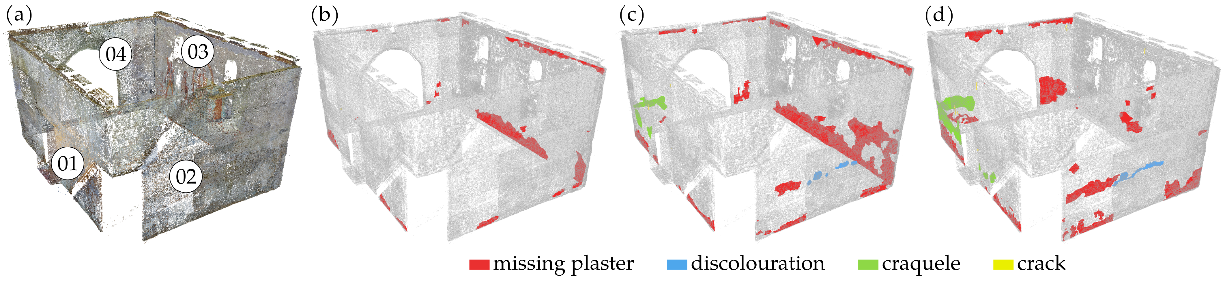
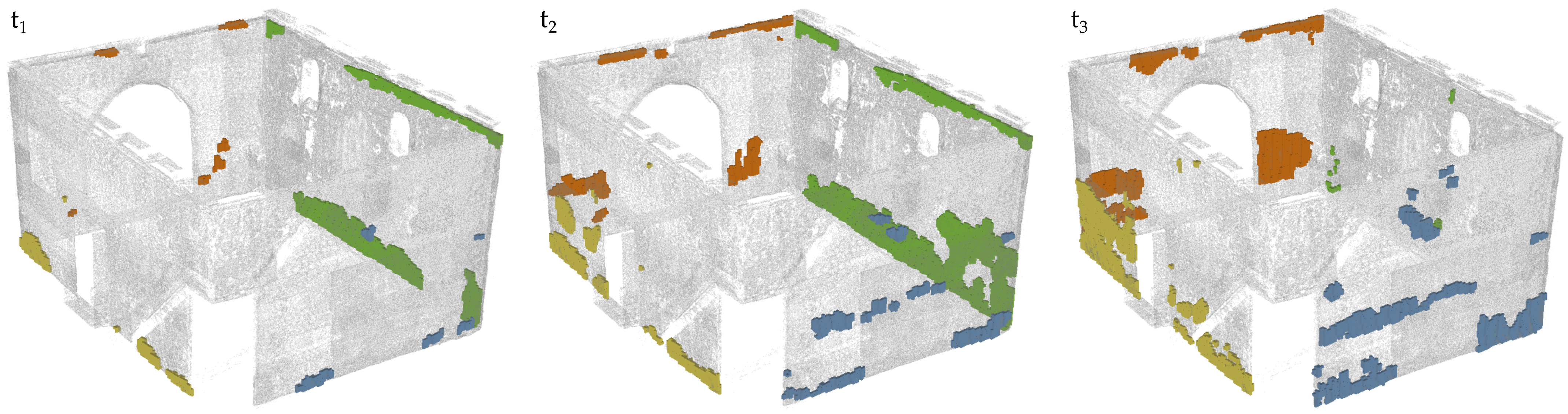
It is possible to replace the mapping or the generation of 3D annotation geometries in this workflow by alternative methods. One other solution could be the mapping of image pixels based on their relative positions to the known salient points of the sparse point cloud, as proposed in Hamdan et al. (2021) [32]. This method uses the pixel-topoint correspondences from the bundler file instead of a ray casting. A similar method was proposed by Manuel et al. (2014) [4], which utilises correspondences from image-based depth maps to segment a damage point cloud from annotated polygons. For visual issues, a model of an already performed photogrammetric reconstruction could also be retextured with a set of pseudo-coloured images according to annotations to consequently keep the labelled damage categories as colours on its surface, as shown in Adamopoulos and Rinaudo (2021) [14]. However, the most direct approach to produce 3D damage geometries is the annotation on 3D models [9,13,15]. Figure 6 presents the results of the mapping process applied to the case study dataset for the main hall, where the 3D damage annotations of the three different states are shown separately. In addition to the increase of damaged regions, it can be seen that some annotations from disappear in due to restoration works on Wall 03.
2.4.2. Assignment of Damages to Building Elements
Once the 3D annotations have been computed or generated, processes to assign the geometries of building elements and damages according to their spatial relationships are applicable. In this section, the assignment of non-sorted 3D annotations to building elements or building sections will be discussed first. Through the workflow in the case study, this assignment may already be derived from the previously described segmentation of the point cloud and image data based on modelled building element surfaces before the annotation (see Section 2.3.2). However, if other methods are used to create the 3D geometries (e.g., by mapped image segmentation [12]) or if annotations are relevant for adjacent elements due to their proximity, the assignments of damages need to be determined from the case study dataset. A linked dataset storing damages, building elements, and their relations is expected as a result.
The most basic methods for an assignment are to check overlapping Axis-Aligned Bounding Boxes (AABBs), bounding boxes with edges parallel to the coordinate axes, which is fast to compute and enables fast collision detection, or the shortest distance between a 3D damage annotation and the building element b of a dataset from an inspection with the timestamp . However, these methods can also lead to erroneous assignments, as described by the authors in Taraben and Morgenthal (2021) [33]. On the one hand, this can be caused by the high inaccuracy of AABBs, which usually include a much larger volume than represented by the actual geometry and overestimate concave geometries. On the other hand, the evaluation of the shortest distance does not give any indication of how affected a building element is by a damage or how much area of the damage actually lies on a building element.
To compensate these issues, each damage geometry was partitioned into equally sized cubic voxels where the distance of each voxel to the building element was evaluated against a distance threshold (dmin). The voxel size (dv) for this and the following operations can be determined by:
- The definition of an octree depth, which is applied to each object and, thus, changes dv according to the object dimension;
- The target accuracy, which needs to consider the registration error, as a global dv, valid for all geometries of the dataset;
- A combined approach, where the octree depth is defined along with a maximum dv to avoid too large voxels for big objects.
The voxelisation allows for the weighting of the assignment result for the damage annotation . The percentage of voxels that are considered to be associated with the building element b or considered intersecting with b is indicated by the value of (see Figure 7). An assignment is now valid, if or, in the case of a defined intersection percentage threshold (pmin), if . In addition to the link between damage and building element, the percentage of assigned voxels and pmin must be stored in the data model in order to be able to reproduce the results at a later time or to filter the assignments.
With a fixed global value for dv, a small damage object could be represented by only a single voxel under specific circumstances. Thus, it is impossible to derive a weighted distance from a voxelisation with this parameter. Considering dynamic dv, this effect does not appear, but also influences the . By the coloured areas in Figure 7, which indicate the voxel evaluation, it is evident that geometries in room corners would be assigned to both adjacent walls using a pure distance-based assignment.
As a result, all damages are assigned to one or more building elements, or vice versa, a building element to the corresponding damages. The amount, type, dimensions and ratings of the damages are thus directly retrievable from the dataset and available for further analyses, such as mechanical simulations or planning of restorations.
2.4.3. Assignment of Damages to Images
From the transformation of the 2D annotations to the 3D building surface, the assignment of damage annotations to images is also derived from the mapping process. Yet, only a 1:n relationship is created between images and damages. However, a damage can usually be contained in several images of an acquired dataset and consequently has an m:n relationship. To assign the remaining images to the damage annotations, for each 3D geometry of a damage, a back-projection into the image plane is reviewed. If this results in a successful representation of the damage in the image, the image is assigned to the damage.
This method was also applied in Manuel et al. (2014) [4] to merge annotations from different images and to include new registered images in the dataset. Additionally, in further image-based condition surveys, the back-projection enables querying images that show detected damages from the last inspection dataset.
2.4.4. Damage Comparison and Evaluation
The presented methods for determining damage assignments referred to data from different domains within a single state. However, the linking of multitemporal data from 3D damage annotations will now be discussed as a first step towards a damage comparison. For this purpose, the elements of a dataset of 3D damage geometries were spatially compared with each other and their proximity was evaluated. An intersection of the geometries, as possible for example in Constructive Solid Geometry (CSG), cannot be applied to the acquired inspection data to detect overlapping areas. The reason for this is that the reconstructions of different states are not congruent due to systematic errors and especially the deformations of the structure itself [34]. Therefore, the reconstructed building surfaces always have a distance to each other, which is also transferred as inaccuracy to the annotations. On a massive church building as in the presented case study, the structural deformation is less than on slender structures, such as bridges or beams, or on severely damaged buildings after earthquakes.
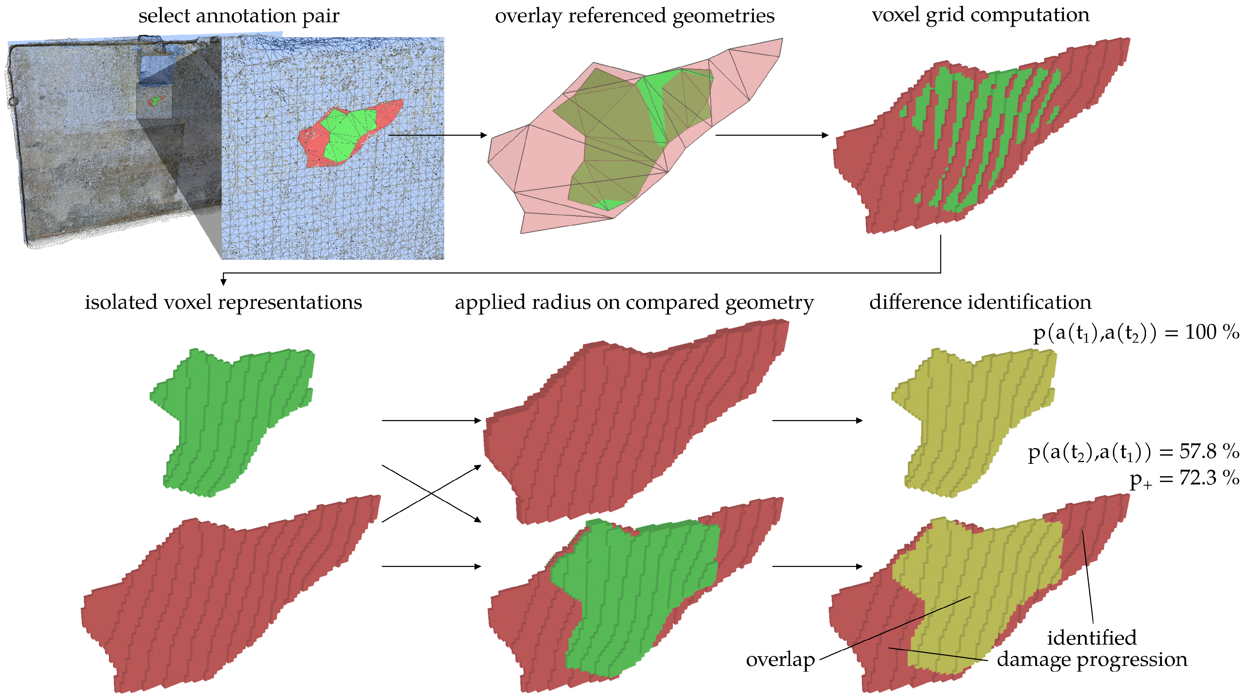
The algorithm for assigning multitemporal 3D damage annotations and of the states and is based on the voxelisation of the geometries [33]. To accelerate the detection of the overlapping AABBs, the geometries arechecked first. Subsequently, a common voxel grid with a defined dv is applied on both geometries and the occupancy of the individual voxels is evaluated. This results in the percentage overlaps and for the percentage of intersection of damage geometry and , respectively. If one of the values is above a defined pmin, the assignment is valid. To compensate the mentioned offset among datasets of different states, an integer voxel radius (rv) is additionally applied, which co-occupies a defined number of neighbouring voxels of a geometry. Figure 8 illustrates the steps of the algorithm with the exemplary damage from the case study dataset.
Due to different styles of annotation, different data characteristics, or changes in the damage structure (e.g., the fusion of decayed regions to one contiguous area), a damage can possibly be assigned to more than one damage from the previous state . Thus, the relationship of the damage assignment is of cardinality 1:n. The assignment already allows for a collection of queries, e.g., to identify:
- Damages that did not occur in a previous inspection and therefore are new to the dataset;
- Damages that no longer occur in the current inspection and therefore need to be surveyed in detail or were repaired during restoration works;
- Damages that in previous inspections were in separate regions and in the current survey fused into one connected damage.
In order to obtain the differential areas, rather than the commonly occupied voxels, only voxels occupied by geometries from or from are extracted and subtracted. Furthermore, rv is applied to compensate the offset, which leads to a maximum deviation:
On the one hand, this deviation prevents the process results from becoming more accurate, except for a recalculation with a decreased dv, but on the other hand, this is also caused by the uncertainty of the building surface registration, which usually would not allow becoming more accurate than the registration itself.
The result of the voxel-based comparison for an assigned set of damages is shown in Figure 8 along with the identification of the localised damage progression. The growth of the same damage among two compared states is expressed as the percentage of detected difference voxels. Thereby, stands for a growth since the previous inspection, since for a shrinkage and for the overlap of the compared damage geometries. Here, due to a better discretisation of the geometry, the accuracy of the percentage value increases with smaller dv, but the computational effort increases at the same time. The percentages of growth and shrinkage enable an automated categorisation or evaluation of the damages. This could also lead to a rating of the damages based on the type of damage, the identified affected building elements, the location on the building element, and the computed damage progression.
2.4.5. Integration with Building Information Models
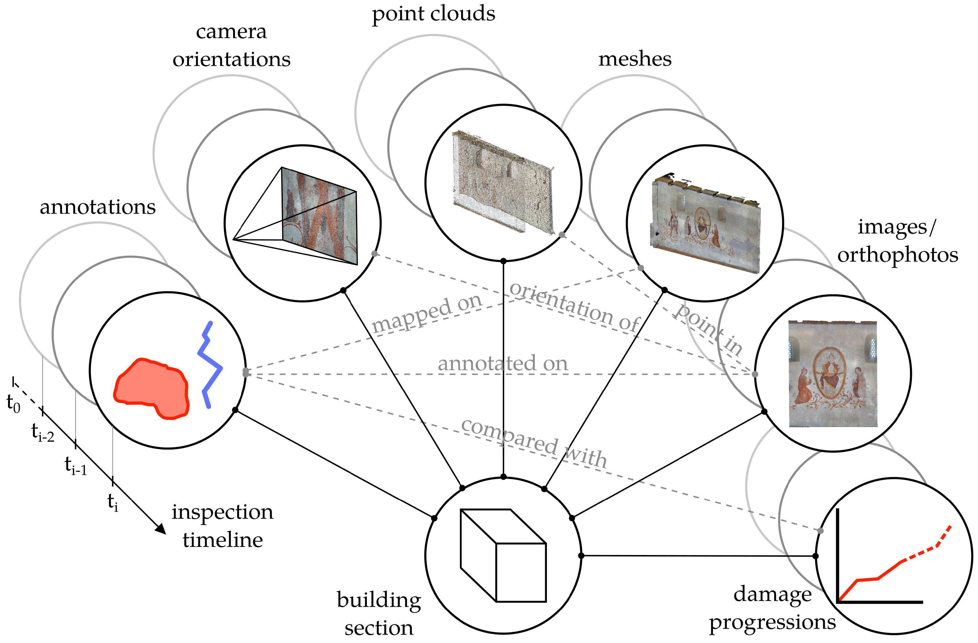
The data model describing such linked inspection data needs to be able to handle the wide range of heterogeneous geometries or refer to them. Among others, this includes point clouds, meshes, camera positions, images, and 2D annotations. In the presented case study, an individual metamodel was specified in the data format JSON, which semantically describes the project hierarchy and properties of the individual data (as a so-called resource), but only refers to them similarly to the multimodel containers proposed by Fuchs and Scherer (2017) [35]. In addition, the determined assignments are stored as links provided with semantics, in order to use them for later analysis processes. This results in an easy-tointerpret dataset of inspection data having the actual geometries and images in specialised data formats according to its application. In the resulting data structure, each resource can be considered as a node of a graph, with the links being the edges of the graph. Direct and indirect links are thus possible to be queried for each resource. Figure 9 presents the possible links for a graph, centred on a particular building element. Furthermore, the links include also multitemporal data, which allows representing the complete status history for each surveyed component.
The linking semantics can also be inverted, e.g., a damage affects a building element and a building element is affected by a damage or a damage is the ancestor of a damage and a damage is the descendant of a damage .
The modelling concept is applicable to other standardised data formats commonly used in the context of Building Information Modelling (BIM), such as the Industry Foundation Classes (IFC) [36] for single buildings or CityJSON [37] for building ensembles. In both cases, this would require conventions or schema extensions to enable the representation of semantics and relationships. However, the data structure provides the basis for such an implementation.
3. Results
In this section, the results of the application of the implemented methods (see Section 2) on the dataset of the Wehrkirche Döblitz are described. For this purpose, the images and point clouds of the main hall were evaluated and annotated and a simplified CAD model of the church building with the walls, floor, and ceiling was created (see Figure 3). Besides the point cloud segmentation and the annotation mapping, the main focus is the application of the voxel-based methods for the assignment and comparison of multitemporal damage geometries (see Section 2.4.4).
3.1. Enriched Building Elements
By voxelising the damage geometries, a weighted assignment between damages and building elements could be determined. The 3D annotations were used as damage geometries, and the surfaces modelled in CAD served as building element geometries. This led to corresponding assignments of damages to each building element (see Table 1).
The dimensions of the 3D annotations are distributed quite heterogeneously depending on the type of damage, which complicates the definition of a common voxel size dv. For the analysis of the dataset, a voxel size of 5 cm was defined in order to obtain a limited number of voxels for relatively large geometries. Alternatively, an adaptive voxel size could be chosen, which is based on the size of the individual damage geometries, e.g., by specifying an octree depth before voxelisation or by considering a percentage of the largest dimension. This would also prevent from one-voxel discretisation of relatively small geometries, which does not lead to the desired weighted distance and, thus, produce instable assignment results. However, dv should then be considered when analysing the results. The distance threshold was defined dependent on the distance of the components to the reconstructed point cloud, which served as the target for ray casting. The number of assigned damages at each inspection applying the discussed parameters is provided for the walls in Table 1. The corresponding voxel evaluation results are presented in Figure 10.
Even without considering the time-varying aspect, this already shows that the method allows for an automated evaluation of the building elements based on the number of assigned damages and their individual characteristics.
3.2. Damage Assignments
After assigning the damage annotations to the corresponding building elements, the assignment of the corresponding images was conducted. This was carried out by backprojecting the damage geometries into the respective cameras and image planes. As an initial filter, the general visibility of the geometries in the image was verified, in order to exclude images that do not contain the required region. The selected images were then filtered by distance to the damage, angle to the centre plane of the damage geometry, or the distance of the 2D annotation to the centre of the image. Figure 11 shows the stepwise filtering process for the described criteria. This process was repeated for each annotation to create the assignments among images and damages.
As mentioned in Section 2.4.3, the process can also be applied to filter images by annotations of previous inspections to perform a targeted inspection of vulnerable areas. The number of images assigned for each damage is listed in Table 2.
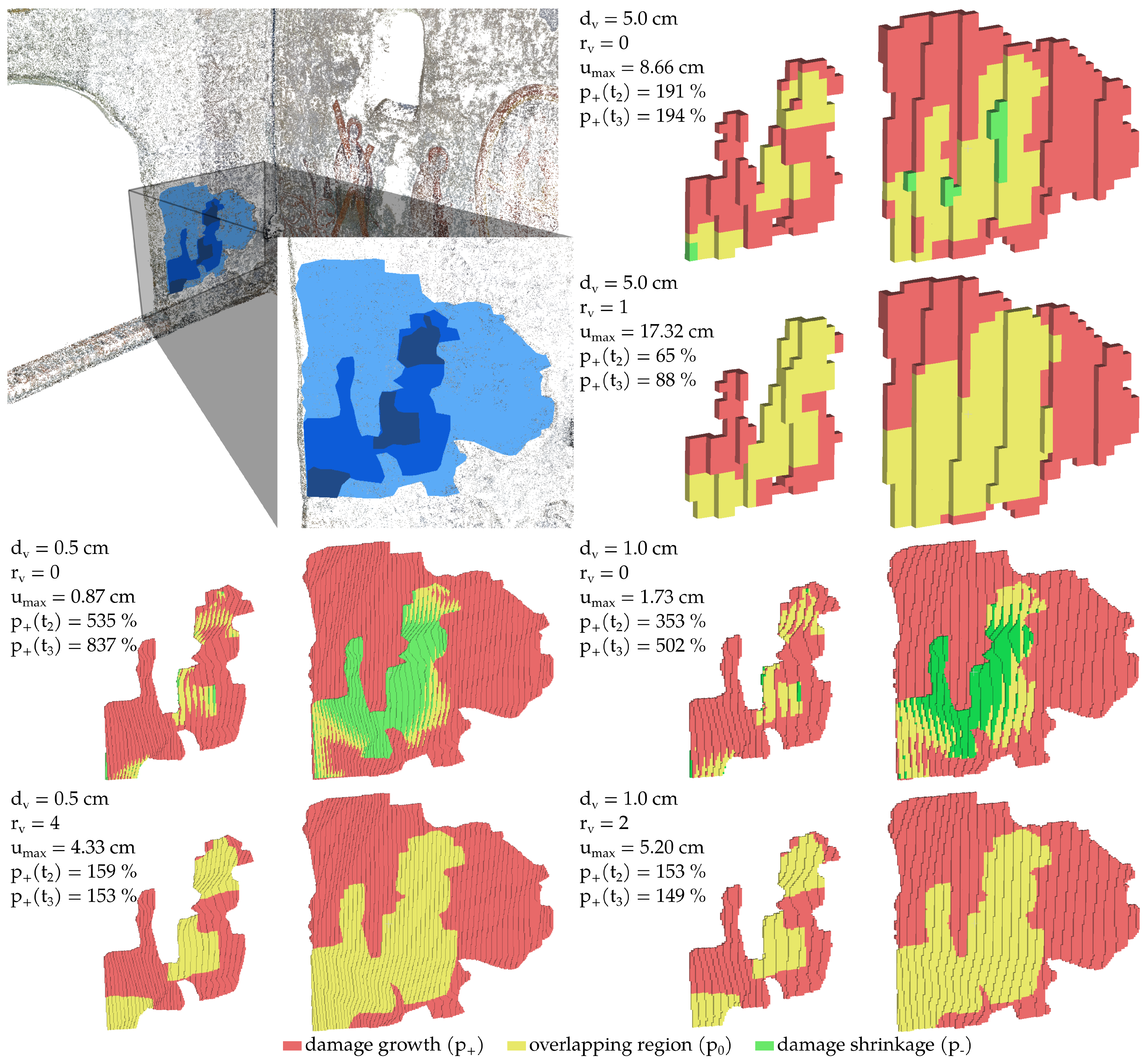
In order to evaluate the multitemporal aspects of the dataset, corresponding damage geometries of two states must first be assigned. As already shown for the assignment of components and damages, a voxel-based process (see Section 2.4.4) is applied for this purpose. The voxel size is once again defined as a global value depending on the dimensions of the damage geometries and the accuracy of the registration (in this case, from the point cloud of to the point cloud of ). In contrast to the assignment of building elements, a smaller dv compensated with a defined voxel radius rv is applied. In Figure 12, a sensitivity study of dv and rv for the comparison of to and to of an exemplary damage is presented. The goal of the study was to identify parameters settings, where the comparison results in reasonable values and those settings that lead to erroneous voxel evaluations. These erroneous evaluations mainly are forced by a too small radius rv.
As previously explained, the case study used a dataset of a single data acquisition and additional synthetic data. Therefore, a random shift of maximum was applied on each vertex of the triangle meshes to simulate the inaccuracies and deformation in multitemporal inspection data. The dataset was further processed with and and a threshold . In Figure 12, the effect of a too small rv can be observed as a detection of damage shrinkage in regions with a larger offset due to deformation or a less accurate registration. It also strongly affects the determined percentage of damage growth from the voxel evaluation. Thus, the product of dv and rv from the chosen parameter settings should exceed the absolute value of the expected offset. For the presented case study, needs to be considered.
Compared to simpler assignment methods such as AABBs or a distance threshold, the advantageous effect of the voxelisation method is in avoiding erroneous assignments of near or partly overlapping damage geometries (see Figure 13). There, the evaluation of the percentage of commonly occupied voxels does not lead to an assignment. Additionally, the procedure after the voxelisation is independent of the geometry class of the damage. For example, missing plaster could be documented as a triangulated surface in one inspection and as a dense point cloud in another inspection. The proposed algorithm could handle both types of data without modifications.
The results of the assignment of images and the comparison explained in the following are listed in Table 2 for Wall 02 of the case study dataset.
3.3. Derivation of Damage Progression
The last step of the automated analysis workflow (see Figure 2) is the comparison of the previously assigned damage groups and the identification of local geometrical changes of damages to derive damage progression indicators.
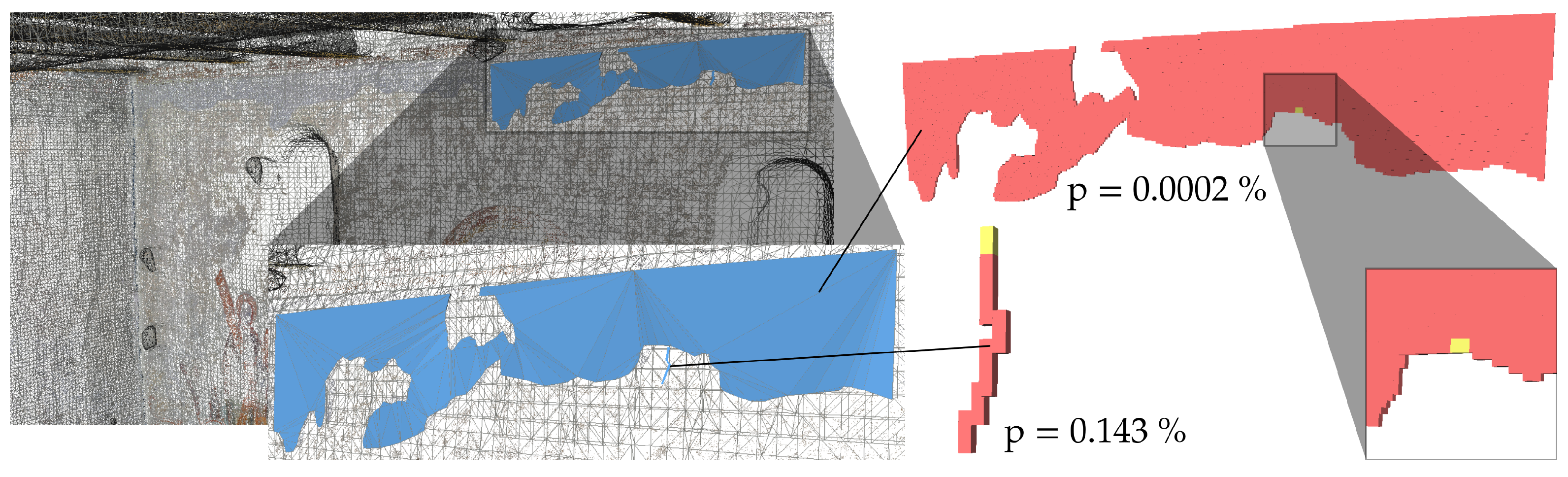
For this purpose, a voxel grid was generated around the assigned damages and evaluated according to the respective timestamps of the surveys. The accuracy of the results depends directly on the accuracy of the registration of the point clouds (or meshes). Since a radius rv must be determined to compensate for the offset, as described in Section 2.4.4, it influences also . The voxel radius rv also helps to shift the discrete geometry more towards a centred position inside the generated voxel representation [33]. This effect does not occur with a rough voxelisation without an applied radius, as shown in Figure 14.
Furthermore, with a smaller voxel size dv, the accuracy of the percentage difference approximation is increased. Figure 15b shows the visual comparison of the dataset of the case study with applied parameters and for all damages. The results of the percentage difference for Wall 02 additionally are listed in Table 2. From the determination of the discrete changes of the damage geometries, the damage increment also allows for a localisation and evaluation depending on its position.
All assignments and computed values presented in Table 2 were stored in the metadata of the corresponding damages in the designed data model (see Section 2.4.5), and their links were stored. Furthermore, the entries in Table 2 show that some damages were first detected in or and that multiple assigned ancestors are also possible. The resulting dataset enables the application of subsequent processes that evaluate the results of the automated workflow, such as condition assessment and rating of the building elements or the derivation of a damage prognosis. In addition to the results produced with the mentioned parameter setting, Figure 15a shows the comparison using a larger dv to visually compare the effects on the entire dataset. A classical damage mapping based on orthophotos, as common in the field of restoration and preservation of cultural heritage, is also possible from these results.
4. Discussion
The digital inspection data collected in the main hall of the Wehrkirche Döblitz was used to perform the integration of image-based 2D annotations into 3D models and to apply automated procedures for the computation of localised geometric changes of damages. For the transfer of the 2D annotations, the triangulated sparse point cloud from photogrammetric 3D reconstruction was used as the ray casting target. Thus, the accuracy of the resulting 3D annotations was strictly related to the accuracy of the photogrammetric reconstruction, leading to different offsets between multitemporal data. The offset could be reduced by a more accurate local registration using methods such as ICP or a compensation of structural deformations by simulated displacement fields. Another way to avoid such offsets would be the projection of the 2D annotations onto a common surface, e.g., of a manually created CAD model, but then, the actual 3D geometries may differ significantly from the projected ones.
The applied voxel-based methods used to assign damages to building elements, images to damages, and damages to damages from previous inspections produced reasonable results. In particular, compared to coarser methods using AABBs or the shortest distance, the voxel-based methods are beneficial in terms of the avoidance of erroneous assignments.
The extraction of localised geometrical changes of multitemporal damage geometries was also carried out using a voxel-based approach. There, the accuracy of the smallest detectable change was again related to the registration of the two photogrammetric reconstructions on which the annotations were based. With increasing offset, the accuracy of the detection of the changes decreased. For damage geometries of a wide range, numerous voxels needed to be generated with the presented method, which significantly increased the computation time.
In summary, a high degree of automation of the comparison of time-varying inspection data and annotations could be achieved. This leads to a sorted and linked data collection that allows for an effective further processing.
5. Conclusions
This article presented a methodological workflow for damage documentation of historic buildings alongside a validation study of a church building in the German region of Vogtland. For this purpose, high-resolution images of the building surface were acquired and the sparse point cloud, as well as the camera orientations were computed by a photogrammetric reconstruction. In addition, the walls, the ceiling, and the floor of the main hall of the church building were manually modelled as simplified CAD geometries. On the captured images, the 2D annotation of visual damages on these building elements was conducted.
In the automated process, presented for the evaluation of these data, the point cloud and the corresponding image data were first segmented on the basis of the modelled building elements. For each segment, the 2D annotations of the damage were transferred into corresponding 3D geometries and linked to the dataset in order to store the relationship between images, components, and damage in a data model. In addition, voxel-based methods were used to automatically identify and localise the geometrical changes over three different states from the generated 3D geometries of the damages.
The choice of the voxel size for the discretisation of the damage geometries was found to be critical for the accuracy of the annotation assignments and comparisons. Therefore, the voxel size should preferably be adapted to the dimensions of the damage and determined adaptively for different elements of a data set in a further development of the method. To overcome the decrease of performance processing large objects, the algorithm could analyse the geometries in fixed grids, which could be evaluated in a parallel process, in order to save computational resources.
The paper highlighted the potential that digital image processing, 3D reconstruction, and systematic condition information modelling have for digital documentation and assessment workflows in the context of heritage preservation. Besides this, the presented methods are also applicable to the field of infrastructure inspections, such as bridges or tunnels, which are surveyed in defined intervals, or the condition assessment after natural disasters to plan rebuilding processes and evaluate the degree of damages. For a subsequent categorisation of the condition assessment of a structure, it is necessary to take into account indicators of changes in damage geometries over different states. Condition scores or assessment criteria should include damage progression and the condition history. In the case of the continuous data acquisition of a structure, the values of identified geometrical changes could possibly also serve as a prognosis of damage progression.
Author Contributions
Conceptualisation, J.T. and G.M.; methodology, J.T. and G.M.; software, J.T.; validation, J.T.; formal analysis, J.T.; investigation, J.T.; data curation, J.T.; writing—original draft preparation, J.T. and G.M.; writing—review and editing, J.T. and G.M.; visualisation, J.T.; supervision, G.M. All authors have read and agreed to the published version of the manuscript.
Funding
This research was funded by the Federal Ministry of Education and Research of Germany, Grant Number 03WIR0706.
Institutional Review Board Statement
Not applicable.
Informed Consent Statement
Not applicable.
Data Availability Statement
Not applicable.
Acknowledgments
The authors would like to thank all researchers and collaborators involved in the research project Wir!–Vogtlandpioniere–Grundlagen der Digitalisierung in Denkmalpflege und Sanierung. Special thanks goes to Norman Hallermann, Florian Madeya, Adrian Teschendorf, Holger Dabbert, Thomas Gebhardt, and Sven Daubert (all Bauhaus-Universität Weimar) for carrying out the data acquisition and point cloud reconstruction. Also, we acknowledge support from the German Research Foundation (DFG) and Bauhaus-Universität Weimar within the program of Open Access Publishing.
Conflicts of Interest
The authors declare no conflict of interest.
References
- Schönberger, J.L.; Frahm, J.M. Structure-from-Motion Revisited. In Proceedings of the 2016 IEEE Conference on Computer Vision and Pattern Recognition (CVPR), Las Vegas, NV, USA, 27–30 June 2016; pp. 4104–4113. [Google Scholar] [CrossRef]
- Hallermann, N.; Morgenthal, G.; Rodehorst, V. Vision-based Monitoring of Heritage Monuments: Unmanned Aerial Systems (UAS) for Detailed Inspection And High-accuracy Survey of Structures. Wit Trans. Built Environ. 2015, 153, 621–632. [Google Scholar] [CrossRef] [Green Version]
- Luhmann, T.; Chizhova, M.; Gorkovchuk, D. Fusion of UAV and Terrestrial Photogrammetry with Laser Scanning for 3D Reconstruction of Historic Churches in Georgia. Drones 2020, 4, 53. [Google Scholar] [CrossRef]
- Manuel, A.; Luca, L.D.; Véron, P. A Hybrid Approach for the Semantic Annotation of Spatially Oriented Images. Int. J. Herit. Digit. Era 2014, 3, 305–320. [Google Scholar] [CrossRef] [Green Version]
- Grilli, E.; Dininno, D.; Petrucci, G.; Remondino, F. From 2D to 3D Supervised Segmentation and Classification for Cultural Heritage Applications. Int. Arch. Photogramm. Remote Sens. Spat. Inf. Sci. 2018, XLII-2, 399–406. [Google Scholar] [CrossRef] [Green Version]
- Poux, F.; Billen, R.; Kasprzyk, J.P.; Lefebvre, P.H.; Hallot, P. A Built Heritage Information System Based on Point Cloud Data: HIS-PC. Isprs Int. J.-Geo-Inf. 2020, 9, 588. [Google Scholar] [CrossRef]
- Alfio, V.S.; Costantino, D.; Pepe, M.; Restuccia Garofalo, A. A Geomatics Approach in Scan to FEM Process Applied to Cultural Heritage Structure: The Case Study of the “Colossus of Barletta”. Remote Sens. 2022, 14, 664. [Google Scholar] [CrossRef]
- Christofori, E.; Bierwagen, J. Recording Cultural Heritage Using Terrestrial Laserscanning–Dealing with the system, the huge datasets they create and ways to extract the necessary deliverables you can work with. ISPRS-Int. Arch. Photogramm. Remote Sens. Spat. Inf. Sci. 2013, XL-5/W2, 183–188. [Google Scholar] [CrossRef] [Green Version]
- Apollonio, F.I.; Basilissi, V.; Callieri, M.; Dellepiane, M.; Gaiani, M.; Ponchio, F.; Rizzo, F.; Rubino, A.R.; Scopigno, R.; Sobra, G. A 3D-centered information system for the documentation of a complex restoration intervention. J. Cult. Herit. 2018, 29, 89–99. [Google Scholar] [CrossRef]
- Vetrivel, A.; Gerke, M.; Kerle, N.; Nex, F.; Vosselman, G. Disaster damage detection through synergistic use of deep learning and 3D point cloud features derived from very high resolution oblique aerial images, and multiple-kernel-learning. Isprs J. Photogramm. Remote Sens. 2018, 140, 45–59. [Google Scholar] [CrossRef]
- Benz, C.; Debus, P.; Ha, H.K.; Rodehorst, V. Crack Segmentation on UAS-based Imagery using Transfer Learning. In Proceedings of the International Conference on Image and Vision Computing New Zealand (IVCNZ), Dunedin, New Zealand, 2–4 December 2019. [Google Scholar] [CrossRef]
- Artus, M.; Alabassy, M.S.H.; Koch, C. A BIM Based Framework for Damage Segmentation, Modeling, and Visualization Using IFC. Appl. Sci. 2022, 12, 2772. [Google Scholar] [CrossRef]
- Dell’Unto, N.; Landeschi, G.; Leander Touati, A.M.; Dellepiane, M.; Callieri, M.; Ferdani, D. Experiencing Ancient Buildings from a 3D GIS Perspective: A Case Drawn from the Swedish Pompeii Project. J. Archaeol. Method Theory 2016, 23, 73–94. [Google Scholar] [CrossRef]
- Adamopoulos, E.; Rinaudo, F. Documenting the State of Preservation of Historical Stone Sculptures in Three Dimensions with Digital Tools. In Pattern Recognition. ICPR International Workshops and Challenges; Del Bimbo, A., Cucchiara, R., Sclaroff, S., Farinella, G.M., Mei, T., Bertini, M., Escalante, H.J., Vezzani, R., Eds.; Lecture Notes in Computer Science; Springer International Publishing: Cham, Switzerland, 2021; Volume 12663, pp. 666–673. [Google Scholar]
- Malinverni, E.S.; Mariano, F.; Di Stefano, F.; Petetta, L.; Onori, F. Modelling in HBIM to Document Materials Decay by a Thematic Mapping to Manage the Cultural Heritage: The Case of “Chiesa della Pietà” in Fermo. ISPRS-Int. Arch. Photogramm. Remote Sens. Spat. Inf. Sci. 2019, XLII-2/W11, 777–784. [Google Scholar] [CrossRef] [Green Version]
- Garagnani, S. Building Information Modeling and real world knowledge: A methodological approach to accurate semantic documentation for the built environment. In Proceedings of the Digital Heritage International Congress (DigitalHeritage), Marseille, France, 28 October–1 November 2013; pp. 489–496. [Google Scholar] [CrossRef]
- Chiabrando, F.; Lo Turco, M.; Rinaudo, F. Modeling the Decay in an HBIM Starting from 3D Point Clouds: A Followed Approach for Cultural Heritage Knowledge. ISPRS-Int. Arch. Photogramm. Remote Sens. Spat. Inf. Sci. 2017, XLII-2/W5, 605–612. [Google Scholar] [CrossRef] [Green Version]
- Rodríguez-Moreno, C.; Reinoso-Gordo, J.F.; Rivas-López, E.; Gómez-Blanco, A.; Ariza-López, F.J.; Ariza-López, I. From point cloud to BIM: An integrated workflow for documentation, research and modelling of architectural heritage. Surv. Rev. 2018, 50, 212–231. [Google Scholar] [CrossRef]
- Costantino, D.; Pepe, M.; Restuccia, A. Scan-to-HBIM for conservation and preservation of Cultural Heritage building: The case study of San Nicola in Montedoro church (Italy). Appl. Geomat. 2021. [Google Scholar] [CrossRef]
- Croce, V.; Caroti, G.; De Luca, L.; Jacquot, K.; Piemonte, A.; Véron, P. From the Semantic Point Cloud to Heritage-Building Information Modeling: A Semiautomatic Approach Exploiting Machine Learning. Remote Sens. 2021, 13, 461. [Google Scholar] [CrossRef]
- Pierdicca, R.; Paolanti, M.; Matrone, F.; Martini, M.; Morbidoni, C.; Malinverni, E.S.; Frontoni, E.; Lingua, A.M. Point Cloud Semantic Segmentation Using a Deep Learning Framework for Cultural Heritage. Remote Sens. 2020, 12, 1005. [Google Scholar] [CrossRef] [Green Version]
- Bitelli, G.; Castellazzi, G.; D’Altri, A.; De Miranda, S.; Lambertini, A.; Selvaggi, I. Automated Voxel Model from Point Clouds for Structural Analysis of Cultural Heritage. Isprs-Int. Arch. Photogramm. Remote Sens. Spat. Inf. Sci. 2016, XLI-B5, 191–197. [Google Scholar] [CrossRef] [Green Version]
- Poux, F.; Billen, R. Voxel-based 3D Point Cloud Semantic Segmentation: Unsupervised Geometric and Relationship Featuring vs Deep Learning Methods. ISPRS Int. J. Geo-Inf. 2019, 8, 213. [Google Scholar] [CrossRef] [Green Version]
- Nan, L.; Wonka, P. PolyFit: Polygonal Surface Reconstruction from Point Clouds. In Proceedings of the 2017 IEEE International Conference on Computer Vision (ICCV), Venice, Italy, 22–29 October 2017; pp. 2372–2380. [Google Scholar]
- Chiabrando, F.; Di Lolli, A.; Patrucco, G.; Spanò, A.; Sammartano, G.; Teppati Losè, L. Multitemporal 3D Modelling for Cultural Heritage Emergency During Seismic Events: Damage Assesment of S. Agostino Church in Amatrice (RI). ISPRS-Int. Arch. Photogramm. Remote Sens. Spat. Inf. Sci. 2017, XLII-5/W1, 69–76. [Google Scholar] [CrossRef] [Green Version]
- Hallermann, N.; Taraben, J.; Morgenthal, G. BIM related workflow for an image-based deformation monitoring of bridges. In Proceedings of the 9th International Conference on Bridge Maintenance, Safety and Management (IABMAS), Melbourne, Australia, 9–13 July 2018; pp. 157–164. [Google Scholar]
- Vetrivel, A.; Duarte, D.; Nex, F.; Gerke, M.; Kerle, N.; Vosselman, G. Potential of Multi-Temporal Oblique Airborne Imagery for Structural Damage Assessment. In Proceedings of the ISPRS Annals of Photogrammetry, Remote Sensing and Spatial Information Sciences, Prague, Czech Republic, 12–19 July 2016; Volume III-3; pp. 355–362. [Google Scholar] [CrossRef]
- Borrmann, A.; Rank, E. Topological analysis of 3D building models using a spatial query language. Adv. Eng. Inf. 2009, 23, 370–385. [Google Scholar] [CrossRef]
- Snavely, N. Bundler v0.4 User’s Manual. 2009. Available online: https://www.cs.cornell.edu/~snavely/bundler/bundler-v0.4-manual.html (accessed on 10 March 2022).
- Wada, K. labelme: Image Polygonal Annotation with Python. 2018. Available online: https://github.com/wkentaro/labelme (accessed on 10 March 2022).
- Kazhdan, M.; Bolitho, M.; Hoppe, H. Poisson Surface Reconstruction. In Proceedings of the Fourth Eurographics Symposium on Geometry Processing (SGP ’06); Sheffer, A., Polthier, K., Eds.; The Eurographics Association: Goslar, Germany; Caglari, Italy, 2006; pp. 61–70. [Google Scholar] [CrossRef]
- Hamdan, A.H.; Taraben, J.; Helmrich, M.; Mansperger, T.; Morgenthal, G.; Scherer, R.J. A semantic modeling approach for the automated detection and interpretation of structural damage. Autom. Constr. 2021, 128, 103739. [Google Scholar] [CrossRef]
- Taraben, J.; Morgenthal, G. Methods for the Automated Assignment and Comparison of Building Damage Geometries. Adv. Eng. Inf. 2021, 47, 101186. [Google Scholar] [CrossRef]
- Taraben, J.; Morgenthal, G. Automated linking of 3D inspection data for damage analysis. In Proceedings of the Bridge Maintenance, Safety, Management, Life-Cycle Sustainability and Innovations (IABMAS); Yokota, H., Frangopol, D.M., Eds.; CRC Press: Sapporo, Japan, 2021; pp. 3714–3720. [Google Scholar] [CrossRef]
- Fuchs, S.; Scherer, R.J. Multimodels—Instant nD-modeling using original data. Autom. Constr. 2017, 75, 22–32. [Google Scholar] [CrossRef]
- buildingSmart. Industry Foundation Classes 4.0.2.1 Version 4.0–Addendum 2–Technical Corrigendum 1. 2017. Available online: https://technical.buildingsmart.org/standards/ifc/ifc-schema-specifications/ (accessed on 10 March 2022).
- Ledoux, H.; Arroyo Ohori, K.; Kumar, K.; Dukai, B.; Labetski, A.; Vitalis, S. CityJSON: A compact and easy-to-use encoding of the CityGML data model. Open Geospat. Data Softw. Stand. 2019, 4, 4. [Google Scholar] [CrossRef]
Figure 1.
The captured point clouds of the Wehrkirche Döblitz (a) from outside and (b) of the main hall and the sanctuary at the ground level and (c) the reconstructed orthophoto of the wall painting.
Figure 1.
The captured point clouds of the Wehrkirche Döblitz (a) from outside and (b) of the main hall and the sanctuary at the ground level and (c) the reconstructed orthophoto of the wall painting.

Figure 2.
Flowchart of the proposed process pipeline to integrate 2D annotations in 3D models and to perform an automated damage comparison (data entities in the white boxes, processing steps without frame).
Figure 2.
Flowchart of the proposed process pipeline to integrate 2D annotations in 3D models and to perform an automated damage comparison (data entities in the white boxes, processing steps without frame).

Figure 3.
Segmented building parts of the main hall with manually modelled building elements: (a) initial point cloud of the interior, (b) modelled facets for floor, walls, and ceiling, (c) explosion drawing of the point cloud segments including the numbering of the walls, and (d) subset of Wall 01 with the extracted image set as camera orientations from the inside.

Figure 4.
Examples of annotated damages: (a) areas of missing plaster (red) and craquele (purple), (b) a crack polyline (light blue) and a small missing plaster detail as a polygon (red), and (c) the synthetic multitemporal labels for the case study in (blue), (yellow), and (red) for a missing plaster area.

Figure 5.
Exemplary mappings of 2D annotations of missing plaster (red) and craqueles (green) from the case study dataset on the triangle mesh surface; (a) an image-based central projection showing the estimated position of the camera p, the focal length f as a vector to the image centre, and the orientation of the local coordinate system and (b) an orthogonal projection from an orthophoto patch, which was registered to the 3D scene.

Figure 6.
Three-dimensional view of (a) the segmented walls with assigned numbering 01–04 and (b,c) the mapped 3D annotations as coloured decay mapping in the states (b) , (c) , and (d) .
Figure 6.
Three-dimensional view of (a) the segmented walls with assigned numbering 01–04 and (b,c) the mapped 3D annotations as coloured decay mapping in the states (b) , (c) , and (d) .

Figure 7.
Three-dimensional views with wall elements and two exemplary 3D annotations from the case study dataset showing the voxel percentage to non-corresponding building elements: (green) assigned voxels and (red) not assigned voxels for octree based or defined voxel sizes with .
Figure 7.
Three-dimensional views with wall elements and two exemplary 3D annotations from the case study dataset showing the voxel percentage to non-corresponding building elements: (green) assigned voxels and (red) not assigned voxels for octree based or defined voxel sizes with .

Figure 8.
Voxel-based assignment and comparison of the exemplary damage from (green) and (red) in the dataset of Wall 02 using the parameters and , resulting in an identified overlap (yellow) and a damage growth of 72.3%.
Figure 8.
Voxel-based assignment and comparison of the exemplary damage from (green) and (red) in the dataset of Wall 02 using the parameters and , resulting in an identified overlap (yellow) and a damage growth of 72.3%.

Figure 9.
Schema of the linking between the different data entities in the case study to achieve a comprehensive condition history on the inspection timeline.
Figure 9.
Schema of the linking between the different data entities in the case study to achieve a comprehensive condition history on the inspection timeline.

Figure 10.
Voxelised () and assigned damages of each annotated state for the wall elements (, = 25%) in the case study dataset: Wall 01 (yellow), Wall 02 (blue), Wall 03 (green), and Wall 04 (orange).
Figure 10.
Voxelised () and assigned damages of each annotated state for the wall elements (, = 25%) in the case study dataset: Wall 01 (yellow), Wall 02 (blue), Wall 03 (green), and Wall 04 (orange).

Figure 11.
Back-projection of a crack annotation on Wall 01 to images containing the damage.

Figure 12.
Results for a missing plaster annotation applying the voxel-based assignment and comparison of (left of each pair) and and (right of each pair) and showing the effects of a too small definition of and the percentage growth computed from different .
Figure 12.
Results for a missing plaster annotation applying the voxel-based assignment and comparison of (left of each pair) and and (right of each pair) and showing the effects of a too small definition of and the percentage growth computed from different .

Figure 13.
Percentage of overlapping voxels (yellow, , ) for two near damage annotations (blue) that are not assigned, whereas a bounding box or distance check would result in a valid assignment.
Figure 13.
Percentage of overlapping voxels (yellow, , ) for two near damage annotations (blue) that are not assigned, whereas a bounding box or distance check would result in a valid assignment.

Figure 14.
Different combinations of dv and rv (all lead to ) for annotated (a) missing plaster surface and (b) crack polyline.
Figure 14.
Different combinations of dv and rv (all lead to ) for annotated (a) missing plaster surface and (b) crack polyline.

Figure 15.
Three-dimensional view of the voxelised and compared full annotation dataset (comparison of and ) in two variants with (a) a rough computation using and and (b) a more detailed computation using and (red: new damaged regions, yellow: regions already identified in , and green: repaired or not re-identified regions).


Table 1.
Result of the damage assignment to the 3D model elements for each inspection.
| Building Element | # of Damages | # of Damages | # of Damages |
|---|---|---|---|
| Wall 01 | 5 | 10 | 21 |
| Wall 02 | 5 | 14 | 14 |
| Wall 03 | 6 | 7 | 17 |
| Wall 04 | 7 | 7 | 8 |
Table 2.
Results of the assignment and comparison workflow for Wall 02, showing the amount of assigned images and the computed percentage damage growth.
Table 2.
Results of the assignment and comparison workflow for Wall 02, showing the amount of assigned images and the computed percentage damage growth.
| ID | Type | # of Images | # of Ancestors from | Growth [%] | # of Ancestors | Growth [%] |
|---|---|---|---|---|---|---|
| tnMdPf | discolouration | 80 | - | - | 5 | 23.5 |
| b8e3vm | missing plaster | 39 | - | - | 1 | 50.5 |
| FXy3KV | missing plaster | 37 | - | - | - | - |
| kk70r3 | missing plaster | 42 | - | - | 1 | 147.6 |
| kZuwv6 | missing plaster | 49 | - | - | 1 | 419.5 |
| lDGeVw | missing plaster | 36 | 1 | 259.1 | 1 | 33.7 |
| Mgg7YP | missing plaster | 57 | 1 | 227.9 | 2 | 143.8 |
| N7ZS4g | missing plaster | 40 | 1 | 51.8 | 1 | 72.8 |
| Q6RCFX | missing plaster | 74 | - | - | 1 | 116.2 |
| whq94c | missing plaster | 104 | 2 | 168.1 | 1 | 152.7 |
| yRCMdN | missing plaster | 36 | - | - | - | - |
| 0H1SWJ | missing plaster | 73 | - | - | - | - |
| 1fKgjk | missing plaster | 40 | - | - | - | - |
| 3AeWJN | missing plaster | 42 | - | - | - | - |
Publisher’s Note: MDPI stays neutral with regard to jurisdictional claims in published maps and institutional affiliations. |
© 2022 by the authors. Licensee MDPI, Basel, Switzerland. This article is an open access article distributed under the terms and conditions of the Creative Commons Attribution (CC BY) license (https://creativecommons.org/licenses/by/4.0/).
Share and Cite
MDPI and ACS Style
Taraben, J.; Morgenthal, G. Integration and Comparison Methods for Multitemporal Image-Based 2D Annotations in Linked 3D Building Documentation. Remote Sens. 2022, 14, 2286. https://0-doi-org.brum.beds.ac.uk/10.3390/rs14092286
AMA Style
Taraben J, Morgenthal G. Integration and Comparison Methods for Multitemporal Image-Based 2D Annotations in Linked 3D Building Documentation. Remote Sensing. 2022; 14(9):2286. https://0-doi-org.brum.beds.ac.uk/10.3390/rs14092286
Chicago/Turabian StyleTaraben, Jakob, and Guido Morgenthal. 2022. "Integration and Comparison Methods for Multitemporal Image-Based 2D Annotations in Linked 3D Building Documentation" Remote Sensing 14, no. 9: 2286. https://0-doi-org.brum.beds.ac.uk/10.3390/rs14092286
Note that from the first issue of 2016, this journal uses article numbers instead of page numbers. See further details here.