Article

Robust Automated Image Co-Registration of Optical Multi-Sensor Time Series Data: Database Generation for Multi-Temporal Landslide Detection

1
Section 1.4-Remote Sensing, GFZ German Research Centre for Geosciences, Telegrafenberg, D-14473 Potsdam, Germany
2
Geoinformation in Environmental Planning Lab, Department of Landscape Architecture and Environmental Planning, TU Berlin, Straße des 17. Juni 145, D-10623 Berlin, Germany
*
Author to whom correspondence should be addressed.
Remote Sens. 2014, 6(3), 2572-2600; https://0-doi-org.brum.beds.ac.uk/10.3390/rs6032572
Submission received: 9 October 2013 / Revised: 13 March 2014 / Accepted: 17 March 2014 / Published: 21 March 2014

Abstract

:
Reliable multi-temporal landslide detection over longer periods of time requires multi-sensor time series data characterized by high internal geometric stability, as well as high relative and absolute accuracy. For this purpose, a new methodology for fully automated co-registration has been developed allowing efficient and robust spatial alignment of standard orthorectified data products originating from a multitude of optical satellite remote sensing data of varying spatial resolution. Correlation-based co-registration uses world-wide available terrain corrected Landsat Level 1T time series data as the spatial reference, ensuring global applicability. The developed approach has been applied to a multi-sensor time series of 592 remote sensing datasets covering an approximately 12,000 km2 area in Southern Kyrgyzstan (Central Asia) strongly affected by landslides. The database contains images acquired during the last 26 years by Landsat (E)TM, ASTER, SPOT and RapidEye sensors. Analysis of the spatial shifts obtained from co-registration has revealed sensor-specific alignments ranging between 5 m and more than 400 m. Overall accuracy assessment of these alignments has resulted in a high relative image-to-image accuracy of 17 m (RMSE) and a high absolute accuracy of 23 m (RMSE) for the whole co-registered database, making it suitable for multi-temporal landslide detection at a regional scale in Southern Kyrgyzstan.

1. Introduction

Landslides are a world-wide occurring natural hazard leading to severe loss of life and infrastructure. A global tendency towards steadily increasing landslide risk can be observed, because of the spreading of settlements in unfavorable regions and the consequences of climate change [1,2]. Against this background, improved understanding of landslide processes in space and time is of great importance, requiring multi-temporal landslide inventories [35]. So far, they have been largely missing for most parts of the world, because of their time and labor intense preparation using conventional mapping methods [57]. In this context, the increasing availability of optical satellite remote sensing data has opened up new opportunities for spatiotemporal analysis of landslide occurrence covering large areas [5,810].
The completeness and quality of remote sensing-based landslide inventories depend on the used multi-temporal image database, whereas a high temporal repetition rate over the longest possible time period of data availability is required in order to perform longer term analysis of landslide occurrence, which is necessary for objective landslide hazard assessment [35]. For this purpose, the global Landsat archive is of key importance, providing free access to the longest available time series of medium-resolution optical satellite remote sensing data [11]. However, in order to achieve the best possible temporal data coverage, multi-sensor data have to be used, resulting in a heterogeneous database of varying spatial and temporal resolution.
Despite this variability, precise image-to-image co-registration has to be ensured for all multi-temporal and multi-sensor datasets, because insufficient spatial fit leads to various ambiguities, resulting in the detection of artifact changes [12,13], as well as incorrect spatial delineation of landslides. The creation of longer term inventories requires maintaining the geometric stability of the image database over several decades, taking into account seasonal and inter-annual landscape changes. Furthermore, the resulting multi-temporal remote sensing database has to be of sufficient absolute positional accuracy related to an external spatial reference system, allowing the combination of information derived from remote sensing analysis with other spatial data, such as GPS-based field measurements within a GIS environment in order to perform subsequent process and hazard analysis.
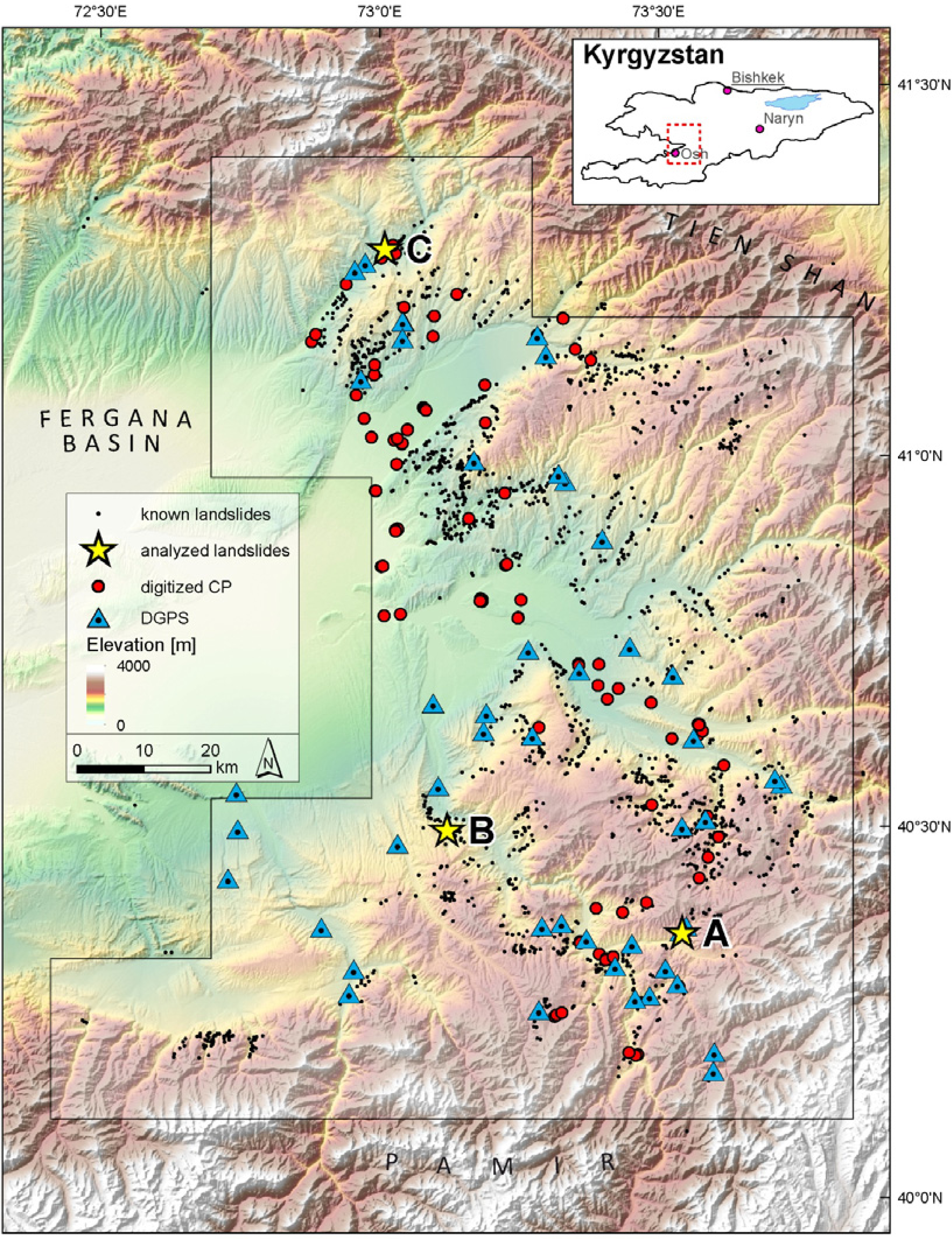
The overall goal of the presented study has been the development and application of a methodology for automated image-to-image co-registration in order to create an image database that is suitable for longer term automated landslide detection within a 12,000 km2 study area in Southern Kyrgyzstan (Central Asia) strongly affected by landslides [
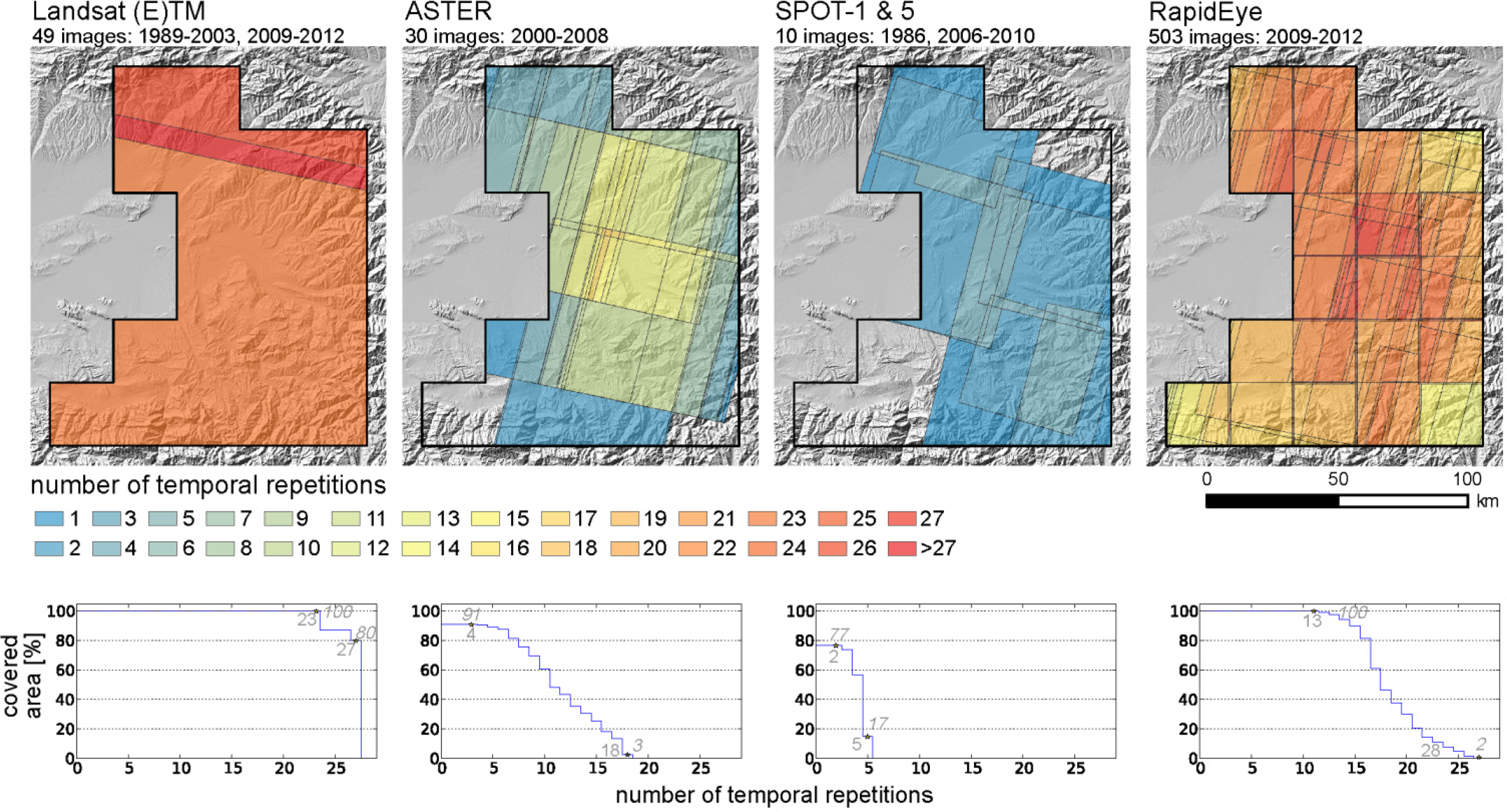
8]. The original image database for this area comprises almost 600 datasets acquired by the multispectral Landsat-(E)TM, SPOT, ASTER and RapidEye satellite systems during the last 26 years. Most of these images were obtained in the form of orthorectified standard data products from the respective satellite data providers. Initial evaluation of the relative spatial fit between these higher-level data products has revealed that significant spatial offsets occur between most of them, including data acquired by the same sensor.
Against this background, the objective has been the development of a co-registration methodology that is suitable to correct for the spatial offsets between large amounts of orthorectified standard data products comprising longer term multi-sensor time series. Thus, the approach has to be able to handle various multi-sensor effects, such as differences between the spatial, spectral and radiometric properties of the image data, as well as multi-temporal effects, such as varying atmospheric, solar and land cover conditions, resulting from seasonal and long-term variability between the image datasets [1416]. Despite the large number of existing methods for automated co-registration, which are comprehensively discussed in Le Moigne et al., 2011 [14], Dawn et al., 2010 [17] and Zitova and Flusser, 2003 [18], only a few of these methods are capable of dealing with multi-sensor and multi-temporal effects at the same time.
In general, the existing co-registration methods are classified into two main categories comprising feature-based and area-based techniques [18]. For accommodating multi-sensor effects during co-registration, feature-based techniques, such as scale-invariant feature transform (SIFT) [19] and speeded-up robust features (SURF) [20], are considered to be more suitable, because these techniques use salient features, such as edges, corners, intersections of linear structures and centroids of distinct geometric objects. These features are expected to be geometrically stable despite the sensor-related variability of the image data [2124]. However, in rural mountainous areas, like Southern Kyrgyzstan, such distinct time-invariant features are often scarce and unevenly distributed, which largely increases the likelihood for significant co-registration errors [21,25]. For such environments, area-based methods are considered to be more suitable, because co-registration is based on identifying distinctive properties for image matching using intensity information rather than local features [21,25]. Hence, area-based methods aim at identifying image areas that are similar in intensity, whereas the commonly used similarity measures are cross-correlation and sequential similarity detection [18,26].
Independent of the used co-registration method, most of the already existing approaches have not been developed for fully automated and efficient processing of big amounts of multi-sensor and multi-temporal image data covering large areas over longer periods of time. Therefore, the practical usability of these methods is often limited, because of the high methodological complexity, the big computational effort, as well as additional requirements specific to the analyzed datasets [15,17,22]. The presented study aims at the development of a robust and globally applicable methodology for automated co-registration, which is suitable for efficient correction of spatial offsets between orthorectified standard data products representing multi-sensor time series.
In this context, a spatially and temporally consistent spatial reference system is required, allowing spatial alignment of all datasets with sufficient relative and absolute accuracy. For this purpose, globally available Landsat Level 1T time series data have been selected as a common spatial reference. They are characterized by sub-pixel image-to-image co-registration accuracy throughout the whole time series [2729], whereas the absolute accuracy of the global Landsat Level 1T database has been estimated to 15 m [27]. Both accuracies are considered to be sufficient for landslide detection at a regional scale. Moreover, Landsat data represent the only source of spatial reference information consistently and repeatedly covering the whole study area, allowing consistent spatial alignment of all time-series datasets, which, in part, are irregularly and patchily distributed over the large study area.
The developed co-registration approach is described in Section 3. The results of spatial alignment are presented in Section 4, comprising sensor-specific analysis for the complete database. In Section 5, the relative and absolute accuracy of the achieved co-registration is analyzed for the whole database, including its influence on the multi-temporal delineation of landslides. The developed methodology is comprehensively discussed in Section 6, focusing on achievable accuracy and overall applicability.

2. Study Area and Spatial Database

2.1. Study Area in Southern Kyrgyzstan (Central Asia)

The study area is located in Southern Kyrgyzstan in Central Asia and covers approximately 12,000 km2 (Figure 1), whereas landslide occurrence is especially concentrated along the Eastern rim of the Fergana Basin in the foothills of the surrounding Tien Shan and Pamir mountain ranges. In this area of high tectonic activity and pronounced topographic relief, landslides are a widespread phenomenon, representing one of the most severe natural hazards to the local population. Landslides vary widely in their sizes, ranging between a few hundred square meters for small events and several hundred thousands or even millions of square meters for large failures [8,30].
Since most of these landslides belong to the rotational and translational types, they cause widespread destruction of the mostly vegetated surface cover and, thus, are well detectable in optical imagery in general [8,31]. Most of these landslides are caused by complex interactions between geological, tectonic, seismic and hydrogeological factors, which have not been well understood, yet. As a result, landslides occur frequently, but at the same time, irregularly throughout the whole study area and cannot be related to distinct triggering events, such as earthquakes and intense rainstorms [8].
In this region, landslides have been investigated since the 1950s, whereas approximately 3000 landslides have been documented (Figure 1). However, regular monitoring has been limited to the time period between 1968 and 1992, focusing on larger settlements and their surroundings, whereas for most of the landslides, coordinate-based geographic locations are missing. Against this background, there is a great need for creating a spatiotemporal landslide inventory covering the whole area (Figure 1).

2.2. Satellite Remote Sensing Database

A multi-temporal database of optical remote sensing data has been created for the study area in Southern Kyrgyzstan. This multi-temporal database consists of 592 multispectral mid- and high-resolution satellite remote sensing images acquired by the Landsat-TM and ETM+, SPOT-1 and -5, ASTER and RapidEye sensors during the last 26 years (Table 1). The spatial resolutions of the contributing sensors range between 30 m for Landsat and 5 m for RapidEye data. They also cover different spectral ranges by varying spectral bands and resolutions. However, all of these sensors represent multispectral instruments comprising the green, red and near-infrared (NIR) spectral bands as the lowest common spectral denominator, allowing comprehensive multi-sensor analysis of landslide-related surface changes.
Almost all of the remote sensing datasets were obtained from the respective satellite data providers in the form of orthorectified standard data products (Table 1) in order to minimize geometric preprocessing efforts and to facilitate the applicability of the developed methodology independent of local ground-truth information, such as GCPs. In the case of SPOT, radiometrically-calibrated Level 1A data were automatically orthorectified using standard orthorectification routines of the ENVI software, which are based on orbital position parameters and a digital elevation model (SRTM). As a result, the established multi-temporal and multi-sensor satellite remote sensing database solely contains orthorectified datasets.
Except for RapidEye, all other datasets have been contained in satellite remote sensing data archives. RapidEye data have been acquired in the frame of the RESA (RapidEye Science Archive) program, allowing customized tasking of data acquisition during pre-defined time periods. Due to the five independent satellites of the RapidEye system [32], a database of high spatial and temporal resolution could be created for the whole region of interest. In total, the database comprises 503 Level 3A standard orthorectified data products characterized by a 5-m pixel size, resulting from cubic convolution resampling of the original 6.5-m RapidEye data. Each of these datasets belongs to one of the fixed 21 RapidEye tiles [33] covering the study area (Figure 2).
Datasets acquired by different sensors vary in their spatial extent between 185 × 170 km2 for Landsat and 25 × 25 km2 for a single RapidEye tile. Therefore, for each sensor, varying numbers of datasets are required to cover the whole region of interest. Figure 2 illustrates the spatiotemporal coverage for the different sensors, whereas the numbers of temporal repetitions are color-coded. The diagrams at the bottom show the number of temporal repetition and their areal coverage of the study area, with maximum and minimum values depicted in grey.
In the case of Landsat, the database contains 49 scenes covering 100% of the study area at least for 23 different acquisition dates, whereas the maximum temporal repetition of 27 acquisition dates could be achieved for 80% of the area during the time period between 1989 and 2012. ASTER (30 scenes) and SPOT (10 scenes) have significantly lower temporal repetitions, with spatial coverage of the study area of 91% and 77%, respectively. RapidEye comprises the highest number of datasets, due to the high temporal repetition and the orthorectified datasets of a relatively small size (25 × 25 km2), resulting in a high number of datasets for a single acquisition date. Temporal repetition varies between 13 and 28 coverages for the different parts of the study area and is almost as high as for Landsat, despite the much shorter acquisition period (4 versus 19 years). Overall, spatial and temporal coverage differs within the study area, because of its large size and the variety of used sensors, representing a challenge to co-registration, since the whole image database has to be transferred into one consistent spatial system. For this purpose, the Landsat Level 1T database has been selected, because it repeatedly covers the whole study area in a spatially consistent way (Section 2.3).
The multi-temporal database is characterized by high seasonal and inter-annual variability of land cover, comprising additional challenges to co-registration. In Figure 3, this variability is exemplarily illustrated for a 6.8 × 7.2 km2 subset of the study area showing color infrared (CIR) visualizations of the image data of all sensors contained in the database acquired during different seasons between 1986 and 2011. Seasonal variability mainly originates from differences in vegetation cover, whereas the period of most intense vegetation development lasts from May until early August, peaking in June. Another seasonal change is the decline of discharge in the river bed during the depicted time span (April–September). Besides these regularly occurring changes, episodic changes can be observed, which are caused by agricultural land use and landslide occurrence. During the depicted period of time, the highest landslide activity can be observed between 2002 and 2004, resulting in a significant increase of landslide affected slopes (yellow ellipses in Figure 3), comparing the datasets acquired in 2004 and 1986.
The small subsets (Figure 3a–f) depicted at the bottom of Figure 3 illustrate the initial spatial offsets occurring between standard orthorectified datasets. The black cross hairs represent the center coordinates of the subsets, whereas the circle-shaped markers indicate an identical point represented by a road crossing. In Figure 3a, the cross hair and the marked point have the same position, whereas for all other subsets, a relative offset can be observed, amounting to a maximum of almost 400 m in the case of SPOT-1 (Figure 3d). This maximum geometric offset is caused by the applied orthorectification procedure that is solely based on orbital position parameters, which have been less accurate for SPOT-1 than for the later SPOT-5. Although, in the case of the other sensors, these offsets are less pronounced, they still amount to up to 60 m and need to be corrected in the process of automated co-registration.

2.3. Spatial Reference Information

2.3.1. Spatial Reference for Co-Registration

In this study, terrain corrected Landsat Level 1T data are used as the spatial reference, while at the same time, they are part of the satellite remote sensing database (Section 2.2). They have been selected because they are freely and widely available and because they represent the only spatially consistent reference information for the whole study area. In contrast, datasets acquired by other sensors either do not cover the complete study area or require many datasets of different acquisition dates and swaths (Figure 2). Such multiple acquisitions result in a spatially and temporally inconsistent data coverage, which is not suitable as the spatial reference. However, since the Landsat reference represents the lowest spatial resolution of the whole database, the co-registration procedure needs to support sub-pixel alignment in order to enable precise co-registration of higher resolution images (Section 3.2).
The Landsat Level 1T data are characterized by sub-pixel image-to-image registration accuracy [2729], enabling the introduction of multiple reference scenes in the co-registration process. Using the reference scenes of different acquisition dates is advantageous, because it accommodates the multi-temporal variability caused by seasonal and long-term land cover changes, which often reduces the accuracy of co-registration [15]. Moreover, Landsat Level 1T data are characterized by an absolute geolocation accuracy of 15 m [27] and, thus, are suitable as the external spatial reference.
Out of all 49 Landsat Level 1T datasets contained in the database, six scenes of three seasonally differing acquisition dates have been selected as the spatial reference. They comprise three mosaics of Landsat ETM+ scenes (path 151; row 31 and 32), which have been acquired on 24 August 2000, 26 May 2002, and 27 April 2003 comprising the main seasonal contrast between abundant green vegetation in spring and mostly dry vegetation in late summer. The Landsat scenes of 24 August 2000, have been identified as the primary spatial reference, which is used as the default. If co-registration to these scenes fails, one of the two other mosaics is selected.

2.3.2. Image-Based Check Points for Relative Accuracy Assessment

The relative accuracy of the co-registration approach is determined by assessing image-to-image accuracy between the single datasets of the remote sensing database. For this purpose, time invariant check points (CPs) were digitized in the Landsat reference. Because of its low spatial resolution of 30 m, only 21 CPs could be identified throughout the mountainous study area. To overcome this limitation, high resolution (5 m and 2.5 m) panchromatic orthorectified SPOT datasets, which are not part of the multi-temporal database, have been manually co-registered to the Landsat reference using the 21 CPs as tie points. Based on these co-registered SPOT images, an additional 65 CPs could be identified in areas of insufficient CP coverage, resulting in a total of 86 CPs. They are mostly represented by streets, intersections and corners of buildings, which were identified in settlements throughout the whole study area (Figure 1). Based on these CPs, the spatial offset of a dataset in relation to Landsat is determined before and after co-registration (Section 5.1).

2.3.3. Differential GPS Points for Absolute Accuracy Assessment

The absolute accuracy of the co-registered remote sensing database is assessed using high accuracy differential GPS (DGPS) points, which were measured in the field in the years 2011 and 2012 with a geolocation accuracy of a few centimeters by a Topcon GB-1000 receiver. This way, the spatial fit of the co-registered image database with spatial information from other sources, such as the results from GPS-based field mapping, can be evaluated. The measured 46 DGPS points (Figure 1) represent corners of buildings and road crossings. However, due to the dominating rural character of the study area, these structures are rather small and, thus, can only be precisely identified in remote sensing data of higher spatial resolution. Therefore, absolute accuracy assessment is only carried out for the co-registered SPOT-5 and RapidEye datasets with a spatial resolution of 10 m and 5 m, respectively (Section 5.2).

2.3.4. Time Series of Digitized Landslides

In order to evaluate the influence of co-registration accuracy on the multi-temporal spatial delineation of landslides, three landslides have been selected, which have not changed their extent since initial failure. These stationary landslides are situated far apart from each other in different parts of the study area (Figure 1). They have been manually digitized in all available multi-temporal datasets before and after co-registration. First, each landslide was digitized in a high-resolution RapidEye dataset. The resulting polygons were used as spatial templates, which, in a second step, have been manually overlaid on the landslide representations in all of the other datasets. This way, errors introduced by multiple manual digitization in datasets of varying spatial resolutions have been omitted, which otherwise would have influenced accuracy assessment (Section 5.3). The number of datasets that were available for multi-temporal digitization differs between the landslides depending on temporal data coverage after failure. Landslides A and B (Figure 1) occurred in 2009. Landslide A could be identified in 25 datasets acquired by three sensors (RapidEye, Landsat, SPOT-5) and Landslide B in 24 datasets acquired by two sensors (RapidEye, Landsat). Landslide C failed in 1999, resulting in its presence in 39 datasets acquired by the Landsat, ASTER, SPOT and RapidEye sensors.

3. Co-Registration of Multi-Temporal and Multi-Sensor Optical Satellite Data

3.1. Overall Approach

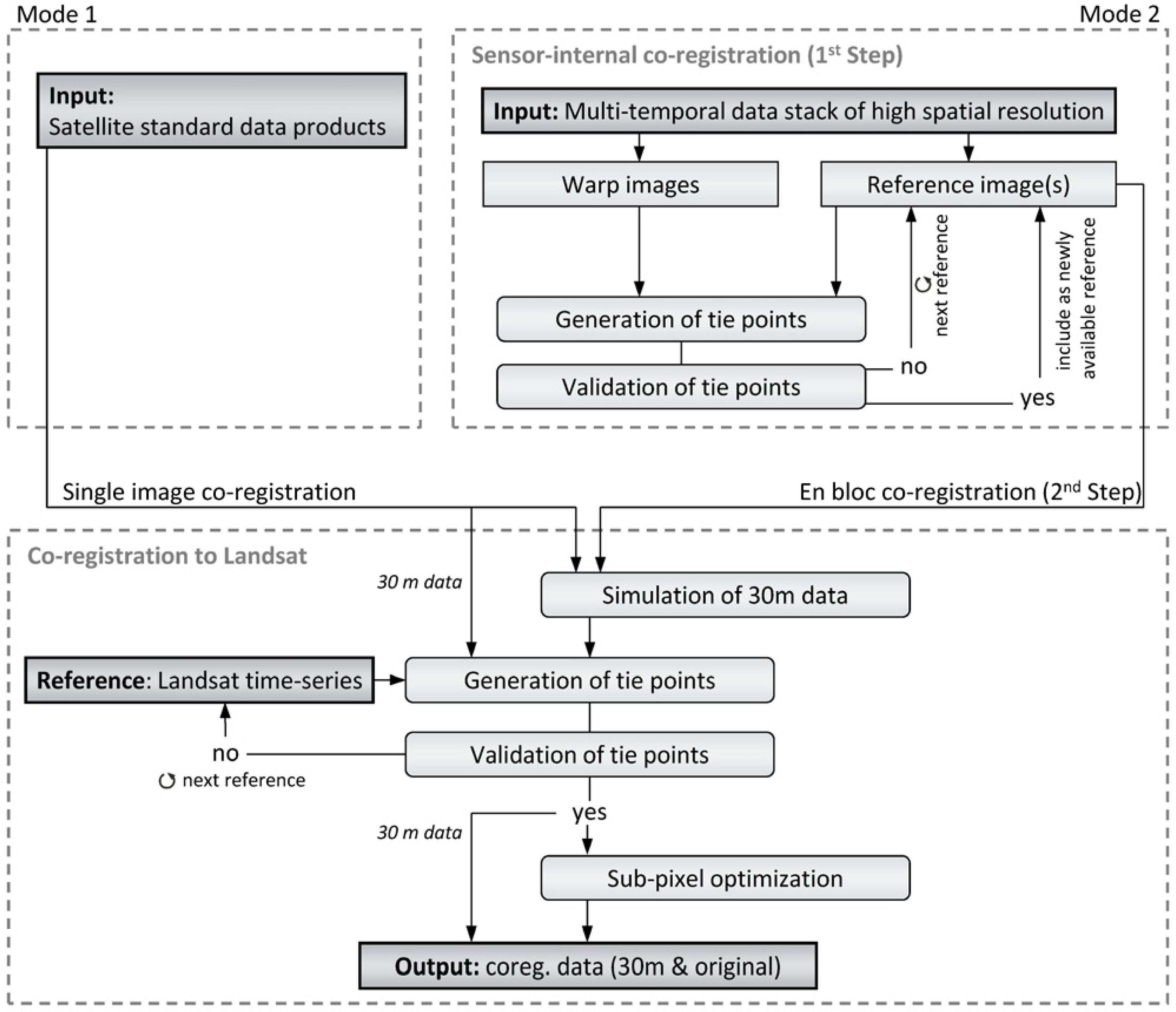
Image-to-image co-registration aims at the spatial alignment of the whole database (Section 2.2) to a common spatial reference represented by the Landsat Level 1T data (Section 2.3.1). The developed co-registration approach (Section 3.2) is based on the assumption that the orthorectified standard data products of the various sensors only differ by constant spatial offsets, which can be corrected by applying image-specific shifts. Checking the fulfillment of this condition for each dataset is an integral part of the co-registration approach, which is depicted in its overall structure in Figure 4.
In order to accommodate the needs originating from the diversity of datasets contained in the comprehensive satellite remote sensing database, two modes have been implemented. The first one enables co-registration of single datasets to the Landsat reference representing the standard case. This mode gets applied if datasets of the same sensor have very small or non-existing spatial overlaps and, thus, cannot be reliably co-registered to each other before aligning them to the Landsat reference. The second mode is applied to data stacks of high temporal and spatial resolution acquired by the same sensor. This two-step mode starts with sensor-internal co-registration of the datasets before they are co-registered en bloc to the Landsat reference using the average of all shifts calculated for the single images of the sensor-internal data stack by the same procedure as in Mode 1. This way, high-accuracy spatial fit between datasets of the same sensor can be achieved or maintained avoiding the uncertainties that get introduced by the co-registration of individual images to a spatial reference of a largely differing spatial resolution. In this study, the second mode has been applied to the RapidEye data, since they are characterized by much higher temporal and spatial resolutions than the Landsat reference and the other medium-resolution satellite remote sensing data, which are co-registered using the first mode.

3.2. Co-Registration to Landsat Reference

Co-registration builds on area-based cross-correlation [17,18,26] that requires the same spatial resolution for the reference image and the warp image. Thus, spatial resampling is a critical step for the performance of the correlation process. In order to get comparable results, downsampling the higher resolution dataset to the lower resolution one is applied, since upsampling of the lower resolution image to the higher resolution one does not allow the reconstruction of spectral details, which are only present in the higher resolution image and, thus, not suitable for correlation purposes. In contrast, downsampling enables the simulation of the spectral signatures of lower resolution data by mixing the spectral information of the higher resolution image. In this study, the warp images of higher spatial resolution are resampled to realistic Landsat pixels by applying a Gaussian filter kernel, which takes into account the spatial resolution of both sensors [34]. The used approach defines the full width at half maximum (FWHM) of the Gaussian kernel as the ratio between the pixel size of the Landsat reference and the pixel size of the warp image. Once both images have the same spatial resolution, the warp image is shifted to the spatial grid of the Landsat reference as a basis for the following correlation.
Using the cross-correlation method, the warp image is co-registered to the reference image by correlating the intensity values within corresponding subsets of the images defined by a moving window. The subset of maximum correlation corresponds to the displacement that is stored in a tie point. In the presented approach, the red and the near infrared (NIR) bands of the input images are used simultaneously, providing a combined overall correlation value. The selection of these bands is performed in an automated way, as long as respective wavelength information is contained in the header files of the warp and reference images. Since the combination of these two bands reacts very sensitively to changes in vegetation cover, high correlation values can only be obtained for temporarily stable vegetated and non-vegetated areas. Moreover, for the correlation window, a relatively large size (51 × 51 pixels) is selected in order to minimize local ambiguities and further increase the robustness of the approach.
The tie point generation process iteratively selects random pixel positions for centering the correlation windows. The correlation coefficient is calculated for each pixel position within a predefined search range, which, by default, is constrained to five pixels, making the approach more robust and computationally less intense. However, this range can be changed depending on the expected offset. If a correlation coefficient is higher than the empirically determined threshold of 0.93, the offset value is stored as the tie point. This process is repeated, until 100 tie points are identified per image pair or 10% of all image pixels have been checked.
In order to validate the identified tie points and to exclude potential outliers, an affine transformation (translation, rotation, scaling) between both images is assumed, because global translation cannot be introduced as an a priori hypothesis. The biggest outliers in regard to the affine model are excluded in an iterative process, until the RMSE is less than one pixel. In the next step, the obtained optimized affine model allows for validating the initial assumption of a global translation. If the scaling or rotation factors of the affine model are negligibly small, i.e., additional offsets at the image corners are less than 1.5 pixels, the global translation transformation is used for co-registration.
If the validation process fails (e.g., due to an unfavorable tie point constellation) or less than 10 tie points per scene remain after the removal of outliers, one of the two other Landsat reference mosaics (Section 2.3) is selected, starting with the one that is seasonally closer to the warp image acquisition date (Figure 4). If none of the reference images meets these quality criteria, the warp image is excluded from the automated processing chain and has to be checked by the user with the option of interactively choosing an affine transformation for image wrapping based on the selected tie points.
In the case of a successful correlation, a final sub-pixel optimization is performed for images of significantly higher spatial resolution than the Landsat reference. In the initial simulation of the 30-m warp image, only one possible centering of the Gaussian filter kernel has been used for resampling to the 30-m resolution warp image. However, in principle, the number of possibilities amounts to the number of original warp image pixels fitting within a single reference pixel, e.g., a 10-m resolution SPOT image results in nine different possibilities for centering the Gaussian filter kernel. Hence, the Gaussian filter kernel is moved in single pixel steps over the original warp image grid around the first centering position of the initial resampling step in order to derive all spatial variations of the 30-m warp image. Then, the correlation process is repeated for all of the resampled 30-m warp images at the position of the already identified tie points. The image characterized by maximized overall correlation represents the sub-pixel optimized co-registered warp image at 30-m resolution.
The final shift comprises the sum of the shifts used to align the warp image grid to the Landsat grid, the 30-m pixel shift resulting from the initial correlation and the original resolution pixel shift originating from the sub-pixel optimization. In the last step, this shift is used to co-register the warp image using a global translation. As a result, two co-registered warp images are produced: one in the spatial resolution of the Landsat reference (the best correlation result) and one in the spatial resolution of the original image data. In the case of the original resolution warp image, the shift is used to update the coordinate reference point, and thus, the image is corrected without any resampling, which maintains the original spectral information of the image after co-registration. Both images are aligned to the Landsat reference grid. The simulated 30-m warp image has exactly the same spatial grid as the reference, whereas in the case of the original warp image, the upper left coordinate is aligned to the reference grid. The achievable accuracy of the approach is determined by the spatial resolution of the original data. If the original datasets have the same spatial resolution as the reference, the steps for simulating the reference resolution and sub-pixel optimization are omitted.

3.3. Sensor-Internal Co-Registration

In Mode 2 of the developed approach, sensor-internal co-registration is performed as the first step before the whole data stack is co-registered en bloc to the Landsat reference. For this purpose, a single dataset is selected from the data stack representing the sensor-internal spatial reference. All of the remaining images of the data stack are co-registered to this reference using the image-to-image area-based correlation algorithm implemented in the first mode without performing the simulation of 30-m data and the following sub-pixel optimization. If a dataset cannot be co-registered (due to a failed validation process or less than 10 identified tie points), it is iteratively correlated with already co-registered images of former iterations, until a good co-registration result can be achieved (Figure 4). This iterative approach allows the co-registration of seasonally differing datasets, resulting in a sensor-internal geometrically-consistent data stack, which is then co-registered en bloc to the Landsat reference. For this purpose, the procedure of Mode 1 is applied to each of the datasets contained in the stack in order to determine the average values for all shifts, which then are used for the en bloc co-registration of the whole data stack.

4. Sensor-Specific Results of the Estimated Shifts

The developed co-registration approach has been applied to all of the 592 image datasets. All of them have passed the validation step, which means that the original orthorectified images have a consistent internal image geometry, which is free of significant distortions. In the following, the shifts obtained by automated co-registration are analyzed separately for each sensor.

4.1. Landsat Datasets

Applying the developed approach to the remaining 43 Landsat Level 1T datasets has resulted in no need for integer pixel shifts, confirming the sub-pixel image-to-image registration accuracy known from the literature [2729]. Co-registration was performed in the standard way (Section 3.2) for all of the datasets, which shows that the datasets are free of internal distortions. This also proves the robustness of the developed approach, accommodating the variability of the image data caused by the presence of clouds and snow, as well as inter-annual and seasonal changes introduced by the time series between 1989 and 2012 and long annual acquisition periods ranging from February to November.

4.2. ASTER and SPOT Datasets

In this study, 42 datasets of ASTER and SPOT have been co-registered to the Landsat reference using Mode 1 of the developed approach. It was possible to co-register all datasets in the standard way, whereas the applied global shifts range between −62 m and +126 m in the east-west direction (X) and between −434 m and +29 m in the north-south direction (Y) (Figure 5). The largest shifts have been obtained for the SPOT-1 images, reflecting the limited accuracy of the standard orthorectification process (Section 2.2). For visualization purposes, these maximum shifts have not been included in Figure 5a, showing all other individual shifts applied to the ASTER and SPOT-5 images.
From the depicted data points, it can be seen that only westward shifts have been applied. Thus, all of the images were originally located east of the Landsat reference with maximum offsets of 48 m for SPOT-5 and 62 m for ASTER datasets (Figure 5b). Furthermore, the analysis of the applied shifts allows for assessing the sensor-internal spatial fit before co-registration. The range of the applied shifts represents the largest spatial difference before co-registration and amounts to approximately three pixels of the original resolution (SPOT-5 (10 m resolution): X: 35 m, Y: 29 m; ASTER (15 m resolution): X: 54 m, Y: 39 m). The standard deviation of the applied shifts for co-registering the images to the Landsat reference can be interpreted as the standard deviation between the orthorectified data products of each sensor before co-registration. It amounts to approximately one original pixel (SPOT-5: X: 13 m, Y: 9 m; ASTER: X: 17 m, Y: 9 m). These results show that for both sensors, the original sensor-internal spatial fit is better in the Y direction than in the X direction.

4.3. RapidEye Datasets

Co-registration of the RapidEye datasets has been performed by applying Mode 2 of the developed approach (Section 3.3). In the first step, sensor-internal co-registration has been carried out. For this purpose, for each of the 21 tiles, one RapidEye dataset was selected as the spatial reference. All of these reference datasets were acquired in May 2011. In the second step, each of the 21 sensor-internal co-registered data stacks were co-registered en bloc to the Landsat reference.
Figure 6 depicts the obtained sensor-internal shifts for all of the 482 co-registered images related to their respective acquisition years (Figure 6a–d), whereas (X) represents shifts in the east-west and (Y) in north-south direction. Part e of Figure 6 summarizes the statistics for all of the applied shifts. Since the original orthorectified RapidEye standard data products are located in a fixed pixel reference grid, only integer pixel shifts have been applied in order to fit the warp image to the sensor-internal RapidEye reference image. The number of datasets with the same applied shift is coded by color and the size of the circle symbols.
Figure 6 shows that the sensor-internal spatial fit between the orthorectified data products was less accurate in 2009 at the beginning of the operational RapidEye mission than in the following years. Maximum shift values amount up to 65 m (13 RapidEye pixels), and large ranges are observed in the X (40 m) and Y (75 m) directions with a strong systematic component in the Y direction. For the datasets acquired in 2010, these ranges are significantly smaller (X: 25 m, Y: 30 m) and less systematic. For most of the datasets acquired during the years of 2011 and 2012 (80% and 66%, respectively), no shift or a maximum shift of one pixel (5 m) has been applied, indicating a greatly improved sensor-internal spatial fit for these years, whereas in Figure 6c and d, hardly any systematic component can be observed. In the diagrams of Figure 6, all datasets with maximum shifts of one pixel are depicted within the black rectangles centered at the origin of the diagrams. Moreover, for the years 2011 and 2012, low standard deviation values of approximately 5 m confirm the high geometric stability of the standard orthorectified data products. Figure 6e also shows that during the whole acquisition period, the spatial fit in the X direction has been more accurate than in the Y direction, which is the opposite of the results obtained for the datasets acquired by the ASTER and SPOT sensors.
Figure 7a summarizes the shifts that have been applied to the 21 sensor-internally co-registered data stacks during the second step; en bloc co-registration to the Landsat reference. In Figure 7b, these shifts are depicted as scaled arrows for each of the 21 tiles. For six data stacks comprising 154 images, the applied shifts amount to 10 m in the western direction and 15 m in the northern direction. The mean shift for all data stacks amounts to 9 m in the western direction and 20 m in the northern direction. Figure 7b shows that all of the applied shifts have a northwestern orientation, indicating that the selected RapidEye reference datasets used for sensor-internal co-registration in Step 1 are systematically offset from the Landsat reference. However, all of the applied shifts are smaller than the spatial resolution of the Landsat reference, and most of the tiles are characterized by rather similar shifts, reflecting the high geometric stability of the selected RapidEye sensor-internal reference datasets throughout the whole study area.

5. Accuracy Assessment

5.1. Relative Image-to-Image Accuracy of the Database

The relative accuracy of the co-registered database is assessed at 86 time invariant check points (CPs) representing the location of the Landsat reference (Figure 1, Section 2.3.2). By using at least 6 CPs per image, the mean spatial offsets (ΔxIM, ΔyIM), the position error (PEIM) and the root-mean-square error (RMSEIM) is determined before and after co-registration. The position error amounts to the mean of the Euclidean distances between the image and the Landsat reference at the locations of the digitized CPs (Equation (3)). The RMSEIM is represented by the square root of the mean of the squares of the position errors at each CP (Equation 4).
Δ x IM = Δ x CP n ; Δ x CP = x CP , warp x CP , ref
Δ y IM = Δ y CP n ; Δ y C P = y CP , warp y CP , ref
PE IM = PE CP n ; PE CP = Δ x CP 2 + Δ y C P 2
RMSE IM = ( PE CP 2 ) n
For evaluating the relative accuracy of the whole database, a representative subset of images has been selected. It comprises images of all sensors, which are characterized by varying offsets and are located in different parts of the study area. In total, three SPOT-5 images, three ASTER images and two SPOT-1 images have been selected. In the case of RapidEye, the representative datasets comprise 12 images, four images per data stack, for three out of the 21 RapidEye tiles.
The data points depicted in Figure 8 represent the mean spatial offsets of the selected images to the Landsat reference in the X and Y direction (ΔxIM, ΔyIM) before co-registration (Figure 8a) and after co-registration (Figure 8b). For visualization purposes, the datasets of SPOT-1 have not been included in Figure 8a, because of their large offsets of more than 400 m (Section 4.2). Statistics of the analyzed distance parameters (ΔxIM, ΔyIM, PEIM, RMSEIM) are shown in the table below (Figure 8c). Before co-registration (Figure 8a), the analyzed datasets are characterized by significantly larger offsets compared to the ones that have remained after co-registration (Figure 8b). After co-registration, all datasets are located closely to the Landsat reference, resulting in a mean PEIM of 16 m, a mean RMSEIM of 17 m and absolute maximum offsets of approximately 20 m in the X and Y directions (ΔxIM: −21 m, ΔyIM: 19 m).
All of these values are smaller than the spatial resolution of the used Landsat reference (30 m), indicating an overall sub-pixel accuracy. The achieved significant improvement in relative accuracy for the whole database is also revealed by comparing the after co-registration mean offset values with the ones obtained before co-registration (mean PEIM: 72 m; mean RMSEIM: 74 m; maximum offsets: ΔxIM: 52 m, ΔyIM: 440 m). Moreover, the offsets remaining after co-registration include a slight systematic error (mean values of ΔxIM: −8 m, ΔyIM: 12 m), which is also deducible from the scatterplot in Figure 8b. However, this distribution also shows high sensor-internal geometric stability as a result of co-registration, especially for the SPOT-5 and RapidEye datasets.
In order to evaluate the relative accuracy, which has been achieved by applying Mode 2, the results obtained for the RapidEye images have been analyzed in more detail. In Figure 8a, each data stack contains four images of different acquisition dates, including one image of early data acquisitions (2009) with offsets of up to 60 m in the Y direction. All other images are characterized by relatively small before co-registration offsets in comparison with the SPOT-5 and ASTER datasets depicted in Figure 8a. After co-registration, the images belonging to the same data stack form clusters with internal offsets of approximately 5 m or less (Figure 8b), representing sub-pixel relative image-to-image registration accuracy, which has been achieved within the same data stack during the first step of co-registration. However, the cluster formed by images of Stack 1 differs in its offset from the offsets of the clusters representing Stacks 2 and 3, which are very similar to each other (Figure 8b). These results show the possibility for slight differences in relative accuracy between data stacks originating from the second step—en bloc co-registration. These differences could be related to the position of the data stack in the study area, which might lead to different land cover conditions influencing co-registration.

5.2. Absolute Accuracy of the Database

The absolute geolocation accuracy achievable by the developed approach is primarily determined by the absolute geolocation accuracy of the Landsat Level 1T reference, amounting to 15 m (RMSE) for Landsat Level 1T products located in areas of flat terrain with optimal ground-truth availability for the standard orthorectification process [27]. For independent assessment of the absolute accuracy of the co-registered database, high accuracy differential GPS (DGPS) points have been used (Section 2.3.3). In 19 co-registered images acquired by the high spatial resolution RapidEye and SPOT-5 sensors, the offsets between DGPS points and their corresponding locations in the co-registered images have been manually determined.
The results of 52 measurements are depicted in Figure 9a, whereas the point of origin represents the location of the DGPS point reference. Statistical analysis of the obtained offsets is shown in Figure 9b. The obtained RMSE of 23 m and the maximum absolute offsets (ΔxDGPS: 27 m, ΔyDGPS: 16 m, PEDGPS: 29 m) reveal overall absolute accuracy in the sub-pixel range compared to the spatial resolution of the Landsat reference (30 m). The low standard deviations of 3 m (X) and 5 m (Y) reflect the high absolute geometric stability of the whole database. Furthermore, the results shown in Figure 9 depict a systematic error of 22 m in the western and 5 m in the northern direction, which implies that the Landsat reference is systematically offset in relation to the measured DGPS points. Due to the high relative accuracy between the Landsat datasets (Section 4.1), this systematic error is assumed to be constant for the whole study area. Therefore, it can be corrected by applying a spatial shift to the whole database resulting from the inversion of the identified average offsets; in this case, 22 m towards the east and 5 m towards the south. As a result, maximum absolute offsets are reduced to approximately 6 m in the X and 10 m in the Y direction (Figure 9b), representing the remaining uncertainty resulting from the relative differences between the datasets..

5.3. Influence of Co-Registration on Spatial Delineation of Landslides

Reliable multi-temporal landslide delineation depends on the quality of the relative spatial fit between the datasets contained in the multi-temporal and multi-sensor database. In order to quantify the influence of the spatial fit on the delineation of landslides, multi-temporal digitization has been performed for three exemplary stationary landslides based on the available datasets before and after co-registration (Section 2.3.4). Figure 10 comprises the analysis of the spatial overlay of the multi-temporal digitized landslides in the form of the number of spatial overlaps between the digitized polygons. Figure 10b,c show the number of these overlaps by a color-coding scheme, where red depicts the area of overlap between all of the digitized landslide polygons and blue the area that is covered by only one of the digitized landslide polygons.
Moreover, a comparison between the spatial extents of the area of overlap between all landslide polygons (area intersect (AI)) and the whole area that is covered by all of the landslide polygons (area union (AU)) has been performed. The results are shown in Figure 10e and f and are quantified in the accompanying table. The AI area depicted in dark grey (10e,f) and red (10b,c) represents the area that is delineated as landslide in all of the multi-temporal datasets. For a stationary landslide, the ideal case of multi-temporal landslide delineation results in a seamless object, indicating spatial identity between AI and AU. A bigger spatial shift between the image data results in a larger AU, shown in light grey and blue colors.
Such an improved spatial fit can be observed for all three landslides depicted in Figure 10, implying that these findings are valid for the whole database. The significance of the achieved improvements mainly depends on the size of the landslide in relation to the offsets occurring between the multi-temporal datasets, whereas the bigger the size of a landslide, the lesser the influence of the spatial offset. In the case of Landslide B, with a length of 1.5 km and an area of approximately 250,000 m2, the offsets of the original datasets result in an AI that is considerably higher (69%) than for Landslide A (19%) and Landslide C (26%). Therefore, in the case of Landslide B, the relative improvement after co-registration only amounts to 26% and is significantly smaller compared to improvements of 65% and 62% for Landslides A and C, respectively.
Furthermore, the uncertainty in landslide delineation resulting from the quality of the spatial fit between datasets can be quantified by the maximum distance of AU (dashed line) to the original polygon shown in Figure 10c. This distance (Max_dist) represents the size of a landslide failure or the enlargement of a landslide that can reliably be detected within the multi-temporal database. In the case of the three analyzed landslides, the uncertainty remaining after co-registration ranges between 6 m and 9 m, representing a significant improvement compared to the uncertainty contained in the original database comprising values between 43 m and 59 m. The remaining uncertainty reflects the relative accuracy of co-registration, which has been achieved for the datasets used for multi-temporal landslide delineation.

6. Discussion

6.1. Applicability of Approach

Validation as part of the co-registration approach has revealed that the developed procedure of image-to-image co-registration using image-specific global shifts in the X and Y directions could be applied to all of the 592 datasets contained in the database, showing the high internal geometric stability of the orthorectified standard data products. The application of the global shift method results in the preservation of the original spectral properties of the standard data products, since there is no need for performing another resampling step.
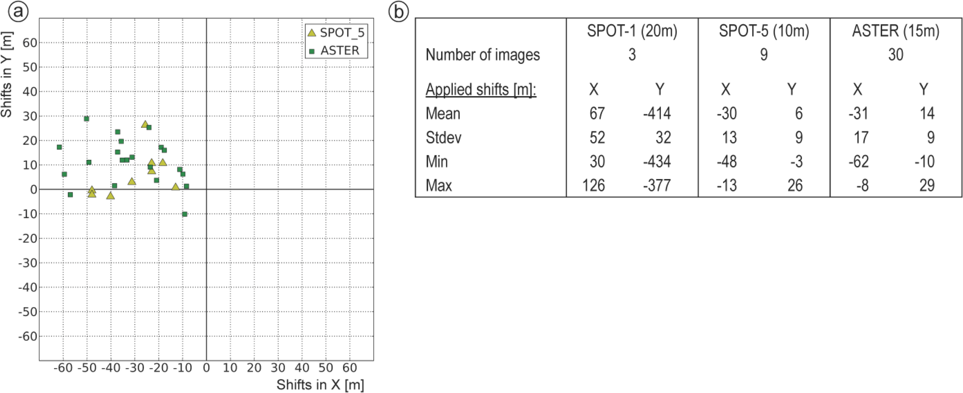
Automated spatial alignment has mostly resulted in shifts of several tens of meters, whereas maximum offsets have been obtained in the case of SPOT-1, amounting to more than 400 m. These results show that the developed approach is capable of handling a wide range of offsets occurring in images of various spatial resolutions ranging between 5 m for RapidEye and 30 m for Landsat data. The successful application of the approach to all datasets also proves its robustness against the variability of image data caused by different multi-sensor and multi-temporal effects, which have the potential for impeding the applicability of co-registration, as well as reducing the achievable accuracy [1416].
Sensor-specific analysis of the applied shifts (Section 4) allows for evaluating the sensor-internal spatial fit between standard data products generated by external providers. In the case of Landsat data, no integer pixel shifts have been applied (Section 4.1), confirming the sub-pixel image-to-image accuracy stated in the literature [2729]. For ASTER and SPOT-5 data, the standard deviations of the applied shifts are less than the respective pixel sizes, and the largest spatial offsets amount to approximately three pixels of the original resolutions (Section 4.2). Sensor-internal RapidEye co-registration (Figure 6) has revealed a steadily improving spatial fit between the datasets since the start of operational data acquisition in 2009, cumulating in offsets of one pixel or less for most of the images acquired in 2011 and 2012. These results are in accordance with the findings of a study assessing the geometric accuracy of the RapidEye constellation [32].

6.2. Accuracy Assessment

Assessment of the relative image-to-image co-registration accuracy based on time-invariant check points (CPs) has resulted in an overall accuracy of 17 m (RMSE) and the maximum remaining offsets to the Landsat reference amounting to 20 m (Section 5.1). Taking into account the 30-m resolution of the Landsat reference, these results indicate the sub-pixel relative accuracy of the whole multi-sensor database. Sensor-specific analysis of the achieved relative accuracy shows high sensor-internal spatial fit for the SPOT-5 and RapidEye datasets, which exceeds the accuracy obtained in relation to the Landsat reference. In the case of RapidEye, the results show that implementation of Mode 2 allows for generating (Step 1) and maintaining (Step 2) high image-to-image accuracies within sensor-internal data stacks during multi-sensor co-registration.
Moreover, it is noticeable that after co-registration, the majority of images still show a small northwestern shift in regard to the Landsat reference (Figure 8b), implying a systematic offset, which is of a significantly lesser amount than one Landsat pixel (mean values of ΔxIM: −8 m, ΔyIM: 12 m). Such a bias could not be observed for the co-registration of the Landsat time series (Section 4.1) and also not for sensor-internal RapidEye co-registration using Step 1 of Mode 2 (Figure 6). Therefore, it is assumed that this small bias is caused by a systematic offset between the Landsat reference and the CPs digitized in panchromatic SPOT-5 datasets, which have been manually co-registered to the Landsat reference (Section 2.3.2). In this case, the detected bias most likely originates from the manual co-registration step and, thus, is not a result of the co-registration approach itself. Direct determination of this offset has not been possible, because of the big difference in spatial resolution between the Landsat reference (30 m) and the panchromatic SPOT-5 datasets (2.5 m and 5 m).
Overall, the achieved relative image-to-image accuracies are comparable or, in parts, even better than the accuracies obtained by other studies dealing with the co-registration of optical time series data. The approach proposed by Gianinetto for automatic co-registration of Level 1A ASTER time series data [16] has resulted in RMSE values of less than two pixels. Liu and Chen [35] have co-registered multi-temporal Formosat-2 Level 1A images (8-m resolution), achieving a RMSE of approximately 1.5 pixels in flat terrain and 2.2 pixels in mountainous areas. Barazetti et al. [36] automatically co-registered 13 Landsat TM datasets acquired over a 30-year period mainly by correcting sub-pixel translation errors, resulting in a relative accuracy of sub-pixel RMSE values. Although, accuracy requirements for co-registration depend on the targets and methods used for change detection [12,37], in general, accuracies (RMSE) of less than one pixel are considered suitable for subsequent change detection [38].
The absolute accuracy of the whole co-registered database, which has been assessed based on DGPS point measurements (Section 2.3.3), amounts to an RMSE of 23 m and a maximum position error of 29 m, whereas a clear systematic error of 22 m in the western and 5 m in the northern direction could be observed. These results indicate that the Landsat reference is systematically offset to the high accuracy DGPS points. This assumption is further supported by the low standard deviation of the derived absolute offsets (X: 3 m, Y: 5 m), implying a high relative accuracy between images, which is of primary importance for subsequent multi-temporal landslide detection.
Due to the availability of the field measured DGPS points and the high geometric stability of the multi-temporal Landsat reference, it is possible to correct for this systematic offset by applying a constant spatial shift. This procedure has resulted in remaining maximum absolute errors of approximately 6 m in the X and 10 m in the Y direction (Section 5.2). However, even the uncorrected absolute offsets are considered to be negligibly small, taking into account the near global availability of the Landsat reference, allowing for the world-wide application of the developed approach without requiring any ground control information. This is especially the case for large area analysis, such as landslide detection at a regional scale.

6.3. Accuracy of Multi-Temporal Landslide Delineation

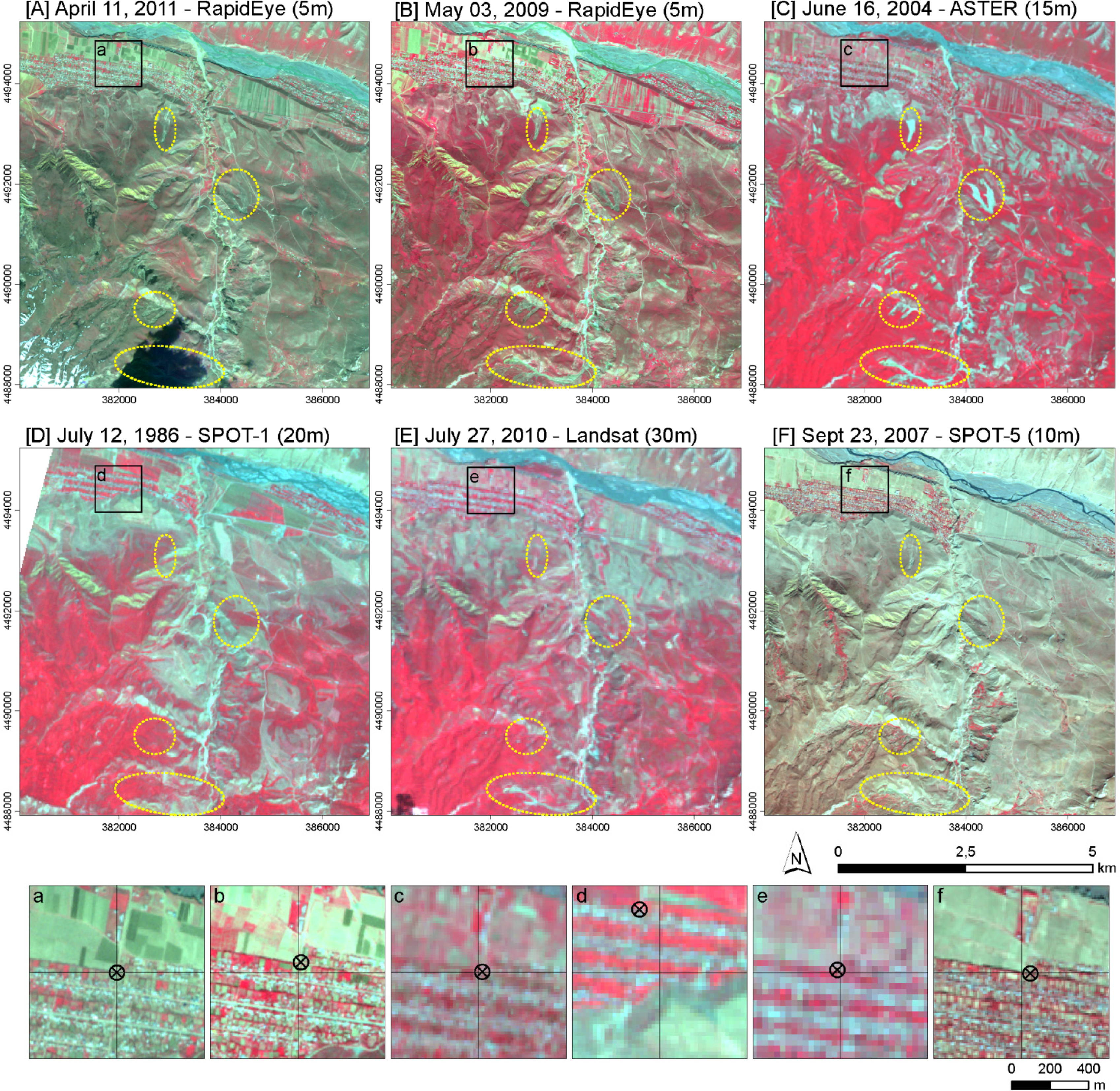
Multi-temporal digitization of three stationary landslides within all datasets covering the landslides before and after co-registration (Section 5.3) has revealed a significant improvement in the relative spatial fit of landslide delineation, reducing the maximum offset from 59 m before co-registration to 9 m after co-registration (Figure 10). These relative accuracies correspond to the maximum absolute offsets, which can be derived for the whole database after correcting for the systematic error introduced by the Landsat reference. These findings indicate that the relative accuracy improvements, which can be observed for all three landslides after co-registration are valid for the whole study area. The remaining relative uncertainty of about 10 m forms a suitable basis for reliable multi-temporal landslide detection, as well as the identification of changes within already existing landslides.
Besides the discussed relative accuracy of landslide delineation, sufficient absolute accuracy is also important for the integration of information derived from remote sensing analysis into a GIS environment for further landslide hazard and risk analysis. Comparing the achieved absolute accuracy of 23 m (RMSE) with the United States National Map Accuracy Standards [39] has shown that the approach meets the requirements for a mapping scale of 1:50,000 and smaller, which is suitable for landslide analysis at a regional scale.

6.4. Methodological Aspects

It could be shown that the developed co-registration approach is suitable for the efficient spatial alignment of a large database containing numerous multi-temporal and multi-sensor standard data products. Incorporation of three seasonally differing Landsat reference datasets has allowed for successful matching of images characterized by high multi-temporal variability. The implementation of a special resampling procedure [34] transforming the spatial resolution of the warp image to the one of the Landsat reference enables the application of area-based cross-correlation to images of varying spatial resolution acquired by different optical sensors.
The methodological constraints of the developed co-registration approach are related to the applied area-based cross-correlation, which is restricted to matching images of only slight affine distortions [18], as well as by the implemented geometric transformation only supporting co-registration based on image-specific two-dimensional shifts. These constraints are attributed to the goal of developing a robust and efficient co-registration approach that can be applied in a fully automatic way to a large number of higher level standard data products, which, in general, are characterized by high internal geometric stability. This assumption could be confirmed for all of the 592 analyzed datasets by an initial validation procedure as part of the co-registration approach. The automatically detected tie points forming the basis for calculating the two-dimensional shifts could also be used in the frame of higher-degree transformation methods, which would allow for correcting more complex local distortions. However, it also needs to be taken into account that higher-degree transformations tend to produce local errors, depending on the spatial distribution and the number of tie points, which has to be larger in order to solve these transformation functions. Furthermore, the use of the two-dimensional shift transformation is more robust against localization errors related to the detected tie points.
In order to preserve the spectral information of the original image datasets for subsequent spectral image analysis, the co-registration approach aligns the original images to the Landsat pixel grid without any further resampling. Thus, the achievable accuracy of the approach is determined by the spatial resolution of the original warp image, allowing for sub-pixel accuracy related to the spatial resolution of the Landsat reference (e.g., 0.16 pixels for 5-m RapidEye data). The implementation of sub-pixel image matching techniques would result in the need for resampling the spectral information of the original warp images and lead to much longer processing times, which would impede the efficient usability of the approach for larger amounts of data.
Compared to other approaches, such as AROP [15], TARA [40] and COSI-CORR [41] aiming at the precise correction of complex geometric distortions, the developed co-registration approach represents a less sophisticated, yet robust and efficient, methodology, which can be applied in a fully automated way to large amounts of multi-sensor time series data, resulting in high relative and absolute accuracy.

7. Conclusions and Outlook

In this study, a new methodology for fully automated co-registration of optical satellite remote sensing data has been developed, allowing for the efficient and robust spatial alignment of big amounts of orthorectified standard data products acquired during the last 26 years for Southern Kyrgyzstan. The co-registration approach is capable of accommodating high image data variability resulting from varying spatial resolutions, as well as seasonal and inter-annual land cover variability. Applying co-registration to the whole database of 592 datasets from five different sensors has resulted in image-specific shifts ranging between 5 m and more than 400 m, showing the robustness of the approach and its suitability for the evaluation of relative spatial fit between standard data products. Moreover, spatial alignment is performed without any further resampling of the initial datasets, maintaining their original spectral information, which is advantageous for subsequent automated image analysis.
Due to the use of freely and globally available Landsat Level 1T data as the spatial reference, the developed methodology is independent of local geometric reference information and can be used in any part of the world covered by suitable Landsat Level 1T data. In this context, the launch of the Landsat-8 Operational Land Imager (OLI) on 11 February 2013, as well as the future Sentinel-2 mission [42] will ensure its future applicability. The overall relative accuracy of 17 m, as well as the absolute accuracy of 23 m (RMSE) represent sub-pixel accuracy in regard to the 30-m resolution of the Landsat reference. These achieved accuracies make the co-registered database suitable for subsequent multi-temporal change detection and for combination with other spatial data within a GIS environment.
The analysis of co-registration accuracy in relation to multi-temporal landslide delineation has revealed maximum relative spatial offsets of six to 9 m between the otherwise unchanged landslides within the multi-temporal database. These offsets correspond to the minimal size of detectable landslide-related changes. However, since this size is also determined by the coarsest resolution of the used datasets, amounting to 30 m, only changes with an extent of more than 900 m2 can reliably be detected. This is more than sufficient for a region dominated by medium-sized to large failures, such as Southern Kyrgyzstan. Achievable relative image-to-image accuracies of the developed co-registration approach could be further improved by using only higher resolution data (e.g., SPOT-5: 10 m and RapidEye: 5 m). Hence, it would be possible to reliably analyze even smaller changes mostly related to the reactivation of already existing landslides.
Altogether, these findings show that the developed methodology is suitable for robust and efficient co-registration of multi-sensor standard orthorectified data products acquired during longer periods of time. The resulting co-registered datasets of high and medium spatial resolution allow for automated landslide detection at a regional scale. Thus, they have the potential for being used for long-term spatiotemporal analysis, as well as for the monitoring of ongoing landslide activity, both contributing to more complete landslide inventories. However, the developed approach cannot only be used for database generation for landslide detection, but also for spatial alignment of any suitable satellite remote sensing time series data in order to perform subsequent analysis of long-term land cover changes in many parts of the world. This way, the developed co-registration methodology supports remote sensing-based analysis of Earth surface processes, which is important for many applied tasks, such as hazard assessment, environmental monitoring and land-use management.

Acknowledgments

The authors gratefully acknowledge the many helpful comments and suggestions from several anonymous reviewers that substantially contributed to clarifying and improving the manuscript. The authors also thank the German Aerospace Agency (DLR) for providing RapidEye data by the RESA (RapidEye Science Archive) program. This work was funded by the German Federal Ministry of Research and Technology (BMBF) within the framework of PROGRESS (Potsdam Research Cluster for Georisk Analysis, Environmental Change and Sustainability).

Author Contributions

Robert Behling and Sigrid Roessner developed the overall approach. Karl Segl and Robert Behling contributed to the methodological development and programming. Robert Behling conducted the image processing and analysis. Robert Behling and Sigrid Roessner prepared the manuscript. Birgit Kleinschmit and Hermann Kaufmann contributed to the discussion and general paper review.

Conflicts of Interest

The authors declare no conflict of interest.

References

  1. Petley, D. Global patterns of loss of life from landslides. Geology 2012, 40, 927–930. [Google Scholar]
  2. Petley, D. On the impact of climate change and population growth on the occurrence of fatal landslides in South, East and SE Asia. Q. J. Eng. Geol. Hydrogeol 2010, 43, 487–496. [Google Scholar]
  3. Van Westen, C.J.; Castellanos, E.; Kuriakose, S.L. Spatial data for landslide susceptibility, hazard, and vulnerability assessment: An overview. Eng. Geol 2008, 102, 112–131. [Google Scholar]
  4. Cascini, L. Applicability of landslide susceptibility and hazard zoning at different scales. Eng. Geol 2008, 102, 164–177. [Google Scholar]
  5. Guzzetti, F.; Mondini, A.C.; Cardinali, M.; Fiorucci, F.; Santangelo, M.; Chang, K.-T. Landslide inventory maps: New tools for an old problem. Earth-Sci. Rev 2012, 112, 42–66. [Google Scholar]
  6. Fiorucci, F.; Cardinali, M.; Carlà, R.; Rossi, M.; Mondini, A.C.; Santurri, L.; Ardizzone, F.; Guzzetti, F. Seasonal landslide mapping and estimation of landslide mobilization rates using aerial and satellite images. Geomorphology 2011, 129, 59–70. [Google Scholar]
  7. Saba, S.B.; van der Meijde, M.; van der Werff, H. Spatiotemporal landslide detection for the 2005 Kashmir earthquake region. Geomorphology 2010, 124, 17–25. [Google Scholar]
  8. Roessner, S.; Wetzel, H.U.; Kaufmann, H.; Sarnagoev, A. Potential of satellite remote sensing and GIS for landslide hazard assessment in Southern Kyrgyzstan (Central Asia). Nat. Hazards 2005, 35, 395–416. [Google Scholar]
  9. Metternicht, G.; Hurni, L.; Gogu, R. Remote sensing of landslides: An analysis of the potential contribution to geo-spatial systems for hazard assessment in mountainous environments. Remote Sens. Environ 2005, 98, 284–303. [Google Scholar]
  10. Othman, A.A.; Gloaguen, R. Automatic extraction and size distribution of landslides in Kurdistan Region, NE Iraq. Remote Sens 2013, 5, 2389–2410. [Google Scholar]
  11. Wulder, M.A.; Masek, J.G.; Cohen, W.B.; Loveland, T.R.; Woodcock, C.E. Opening the archive: How free data has enabled the science and monitoring promise of Landsat. Remote Sens. Environ 2012, 122, 2–10. [Google Scholar]
  12. Sundaresan, A.; Varshney, P.; Arora, M. Robustness of change detection algorithms in the presence of registration errors. Photogramm. Eng. Remote Sens 2007, 73, 375–383. [Google Scholar]
  13. Townshend, J.; Justice, C.; Gurney, C.; Mcmanus, J. The impact of misregistration on change detection. IEEE Trans. Geosci. Remote Sens 1992, 30, 1054–1060. [Google Scholar]
  14. Le Moigne, J.; Netanyahu, N.S.; Eastman, R.D. Image Registration for Remote Sensing; Cambridge University Press: Cambridge, UK, 2011; p. 484. [Google Scholar]
  15. Gao, F.; Masek, J.; Wolfe, R.E. Automated registration and orthorectification package for Landsat and Landsat-like data processing. J. Appl. Remote Sens 2009, 3, 033515. [Google Scholar]
  16. Gianinetto, M. Automatic co-registration of satellite time series. Photogramm. Rec 2012, 27, 462–470. [Google Scholar]
  17. Dawn, S.; Saxena, V.; Sharma, B. Remote sensing image registration techniques: A survey. Image Signal Process 2010. [Google Scholar] [CrossRef]
  18. Zitova, B.; Flusser, J. Image registration methods: A survey. Image Vis. Comput 2003, 21, 977–1000. [Google Scholar]
  19. Lowe, D.G. Distinctive image features from scale-invariant keypoints. Int. J. Comput. Vis 2004, 60, 91–110. [Google Scholar]
  20. Bay, H.; Ess, A.; Tuytelaars, T.; van Gool, L. Speeded-Up Robust Features (SURF). Comput. Vis. Image Und 2008, 110, 346–359. [Google Scholar]
  21. Huang, L.; Li, Z. Feature-based image registration using the shape context. Int. J. Remote Sens 2010, 31, 2169–2177. [Google Scholar]
  22. Cao, S.; Jiang, J.; Zhang, G.; Yuan, Y. An edge-based scale- and affine-invariant algorithm for remote sensing image registration. Int. J. Remote Sens 2013, 34, 2301–2326. [Google Scholar]
  23. Brook, A.; Ben-Dor, E. Automatic registration of airborne and spaceborne images by topology map matching with SURF processor algorithm. Remote Sens 2011, 3, 65–82. [Google Scholar]
  24. Bouchiha, R.; Besbes, K. Automatic remote-sensing image registration using SURF. IJCTE 2013, 5, 88–92. [Google Scholar]
  25. Chen, H.M.; Arora, M.K.; Varshney, P.K. Mutual information-based image registration for remote sensing data. Int. J. Remote Sens 2003, 24, 3701–3706. [Google Scholar]
  26. Fonseca, L.M.; Manjunath, B.S. Registration techniques for multisensor remotely sensed imagery. Photogramm. Eng. Remote Sens 1996, 62, 1049–1056. [Google Scholar]
  27. Storey, J.; Choate, M.; Lee, K. Geometric Performance Comparison between the OLI and the ETM+. Proceedings of the PECORA 17 Conference, Denver, CO, USA, 18–20 November 2008.
  28. Kennedy, R.E.; Yang, Z.; Cohen, W.B. Detecting trends in forest disturbance and recovery using yearly Landsat time series: 1. LandTrendr—Temporal segmentation algorithms. Remote Sens. Environ 2010, 114, 2897–2910. [Google Scholar]
  29. Lee, D.S.; Storey, J.C.; Choate, M.J.; Hayes, R.W. Four years of Landsat-7 on-orbit geometric calibration and performance. IEEE Trans. Geosci. Remote Sens 2004, 42, 2786–2795. [Google Scholar]
  30. Schlögel, R.; Torgoev, I.; de Marneffe, C.; Havenith, H.-B. Evidence of a changing size–frequency distribution of landslides in the Kyrgyz Tien Shan, Central Asia. Earth Surf. Proc. Land 2011, 36, 1658–1669. [Google Scholar]
  31. Lacroix, P.; Zavala, B.; Berthier, E.; Audin, L. Supervised method of landslide inventory using panchromatic SPOT5 images and application to the earthquake-triggered landslides of Pisco (Peru, 2007, Mw8.0). Remote Sens 2013, 5, 2590–2616. [Google Scholar]
  32. Chander, G.; Haque, M.O.; Sampath, A.; Brunn, A.; Trosset, G.; Hoffmann, D.; Roloff, S.; Thiele, M.; Anderson, C. Radiometric and geometric assessment of data from the RapidEye constellation of satellites. Int. J. Remote Sens 2013, 34, 5905–5925. [Google Scholar]
  33. BlackBridge: Delivering the World. Available online: http://www.blackbridge.com/rapideye/products/ortho.htm (accessed on 17 January 2014).
  34. Mueller, M.; Segl, K. Simulation of high resolution imagery. In Operational Remote Sensing for Sustainable Development; Nieuwenhuis, G.J.A., Vaughan, R.A., Molenaar, M., Eds.; Balkema: Rotterdam, The Netherlands, 1999; pp. 331–338. [Google Scholar]
  35. Liu, C.-C.; Chen, P.-L. Automatic extraction of ground control regions and orthorectification of remote sensing imagery. Opt. Express 2009, 17, 7970–7984. [Google Scholar]
  36. Barazzetti, L.; Scaioni, M.; Gianinetto, M. Automatic co-registration of satellite time series via least squares adjustment. Eur. J. Remote Sens 2014, 47, 55–74. [Google Scholar]
  37. Bruzzone, L.; Bovolo, F.; Marchesi, S. A Multiscale Change Detection Technique Robust to Registration Noise. Proceedings of the Pattern Recognition and Machine Intelligence, Kolkata, India, 18–22 December 2007; 4815, pp. 77–86.
  38. Jianya, G.; Haigang, S.; Guorui, M.; Qiming, Z. A review of multi-temporal remote sensing data change detection algorithms. Int. Arch. Photogramm. Remote Sens. Spat. Inf. Sci 2008, 37, 757–762. [Google Scholar]
  39. USGS—National Geospatial Data Standards—United States National Map Accuracy Standards. Available online: http://nationalmap.gov/standards/nmas.html (accessed on 17 January 2014).
  40. Le Moigne, J.; Cole-Rhodes, A.A.; Eastman, R.D.; Netanyahu, N.S.; Stone, H.S.; Zavorin, I.; Morisette, J.T. Multitemporal and Multisensor Image Registration. In Image Registration for Remote Sensing; LeMoigne, J., Netanyahu, N.S., Eastman, R.D., Eds.; Cambridge University Press: Cambridge, UK, 2011; pp. 293–338. [Google Scholar]
  41. Leprince, S.; Barbot, S.; Ayoub, F.; Avouac, J.-P. Automatic and precise orthorectification, coregistration, and subpixel correlation of satellite images, application to ground deformation measurements. IEEE Trans. Geosci. Remote Sens 2007, 45, 1529–1558. [Google Scholar]
  42. Drusch, M.; del Bello, U.; Carlier, S.; Colin, O.; Fernandez, V.; Gascon, F.; Hoersch, B.; Isola, C.; Laberinti, P.; Martimort, P.; et al. Sentinel-2: ESA’s optical high-resolution mission for GMES operational services. Remote Sens. Environ 2012, 120, 25–36. [Google Scholar]
Figure 1. Study area in Southern Kyrgyzstan. (Inset) The location within Kyrgyzstan (depicted as a red dashed line). (Main figure) The location of known landslides and reference information for accuracy assessment in Section 5 (check points (CPs), differential GPS (DGPS) points and analyzed landslides) within the study area, depicted as a transparent polygon overlay.
Remotesensing 06 02572f1
Figure 2. Maps depict sensor-specific spatiotemporal coverage of the study area. Diagrams show the number of temporal repetitions and the related areal coverage of the study area.
Remotesensing 06 02572f2
Figure 3. Exemplary representation of multi-temporal time series (1986–2011) (AF) Color infrared (CIR) visualization of seasonal differing multi-sensor datasets; selected landslide prone areas are depicted by yellow dashed ellipses. (af) The geometric offsets within the time series.
Remotesensing 06 02572f3
Figure 4. The overall structure of the developed co-registration approach.
Remotesensing 06 02572f4
Figure 5. Shifts applied during co-registration to Landsat reference (in rounded meters), X: east-west; Y: north-south. (a) The scatterplot of the shifts contains all individual datasets; (b) The sensor-specific statistics of applied shifts.
Remotesensing 06 02572f5
Figure 6. Applied shifts for sensor-internal co-registration of RapidEye. (ad) The obtained shifts are related to the acquisition year. The number of images with the same shift is indicated by the color and size of the circle symbols. All symbols falling within the black rectangles represent datasets shifted by one pixel or less. (e) The table of statistics.
Remotesensing 06 02572f6
Figure 7. En bloc shifts applied to RapidEye data stacks represented by Level-3A tiles: (a) The number of data stacks (tiles) and related images with that particular shift; (b) The direction and amount of shift for each data stack depicted by scaled arrows (tile size: 25 × 25 km2).
Remotesensing 06 02572f7
Figure 8. Relative accuracy: the relative location of datasets to the Landsat reference (represented as the point of origin) (a) before co-registration and (b) after co-registration; (c) statistics of the offsets (in meters).
Remotesensing 06 02572f8
Figure 9. Absolute accuracy: the location of the co-registered datasets in relation to the DGPS points (represented as the point of origin).
Remotesensing 06 02572f9
Figure 10. Influence of co-registration on multi-temporal landslide delineation for three stationary landslides before and after co-registration. (a) Field photo; (d) Digitized landslide; (b,c) The number of overlapping datasets; (e,f) Overlapping area of all datasets (area intersect (AI)); area covered by all landslide polygons (area union (AU)). Image: RapidEye 2 May 2011.
Remotesensing 06 02572f10
Table 1. Optical satellite remote sensing database.
SensorResolution (m)Swath Width, Extent (km)Spectral Range (nm)No. of BandsTime periodAcquisition DatesDatasetsProduct LevelProvider
RapidEye577, 25 × 25440–85052009–2012515033ABlackBridge
SPOT-51060, 60 × 60500–175042006–2010591ASPOT IMAGE
ASTER15–9060, 60 × 60520–2430142000–200820303A 01ASTER GDS
SPOT-12060, 60 × 60500–89031986231ASPOT IMAGE
Landsat TM30185, 185 × 170450–235071989–1999
2009–2012
14251TUSGS GLS
Landsat ETM+30185, 185 × 170450–235081999–200313241TUSGS GLS

