
ASTC-MIMO-TOPS Mode with Digital Beam-Forming in Elevation for High-Resolution Wide-Swath Imaging


Abstract
:
1. Introduction
2. TOPS Imaging Mode
2.1. Recent Proposed SAR Modes for HRWS Imaging

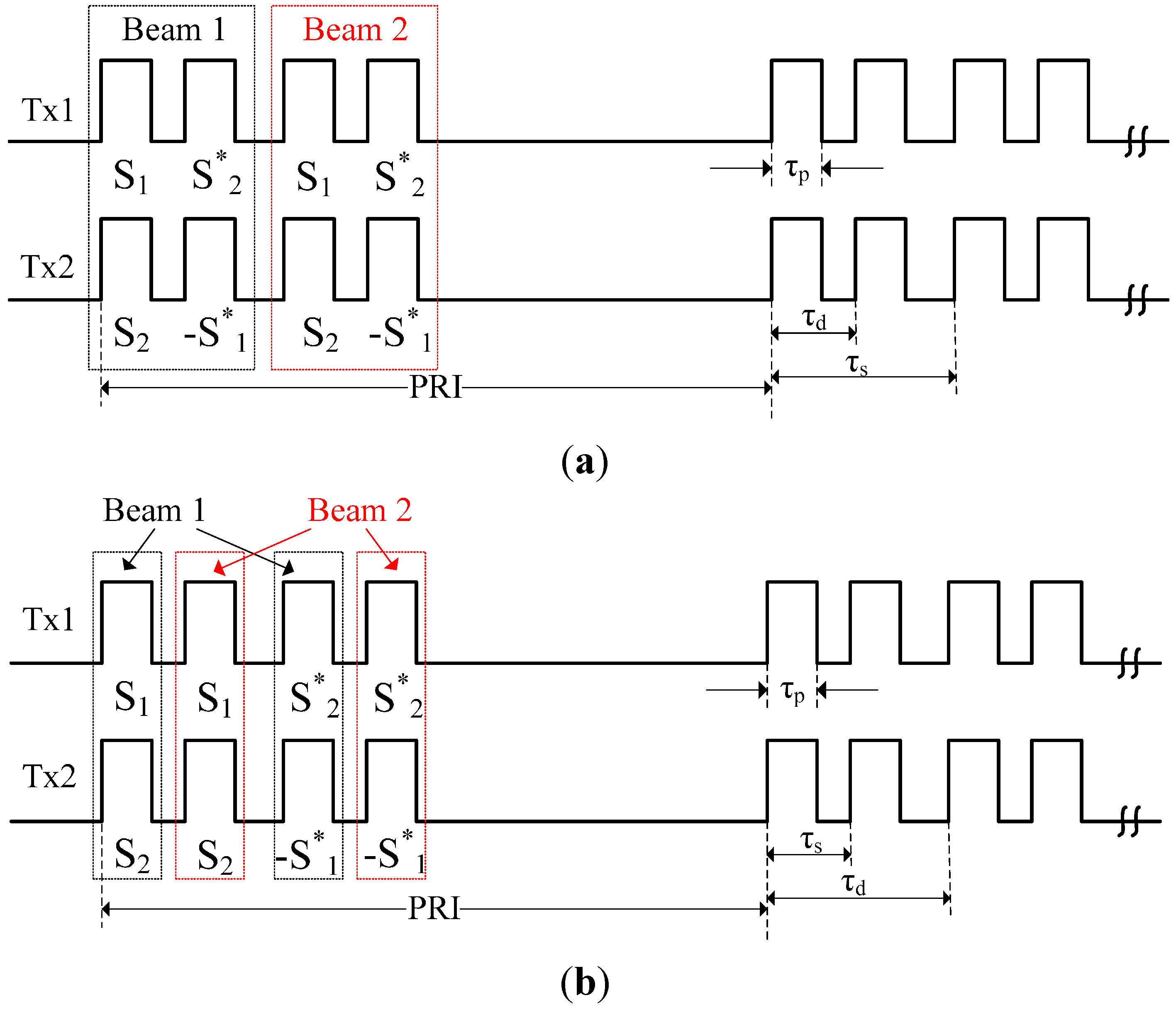
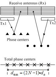
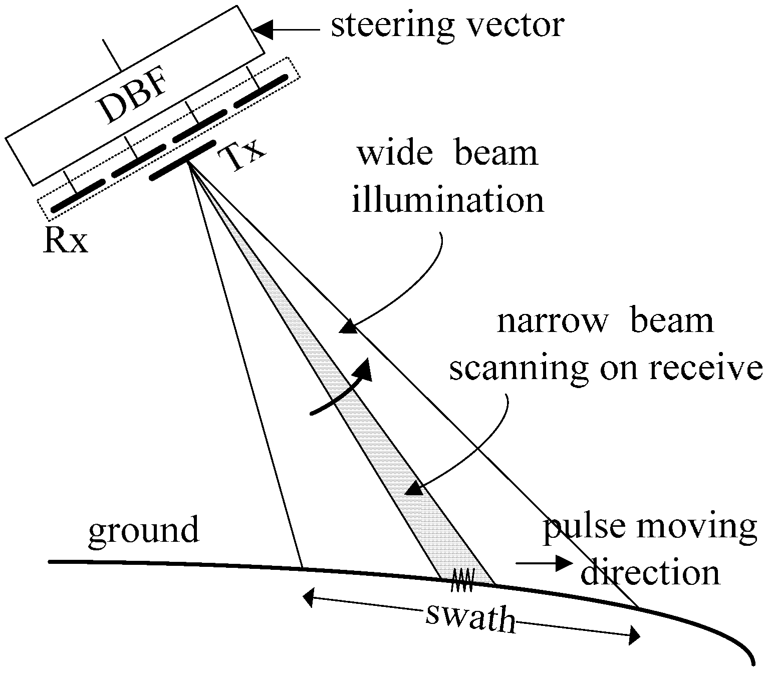
2.2. ASTC-MIMO-TOPS

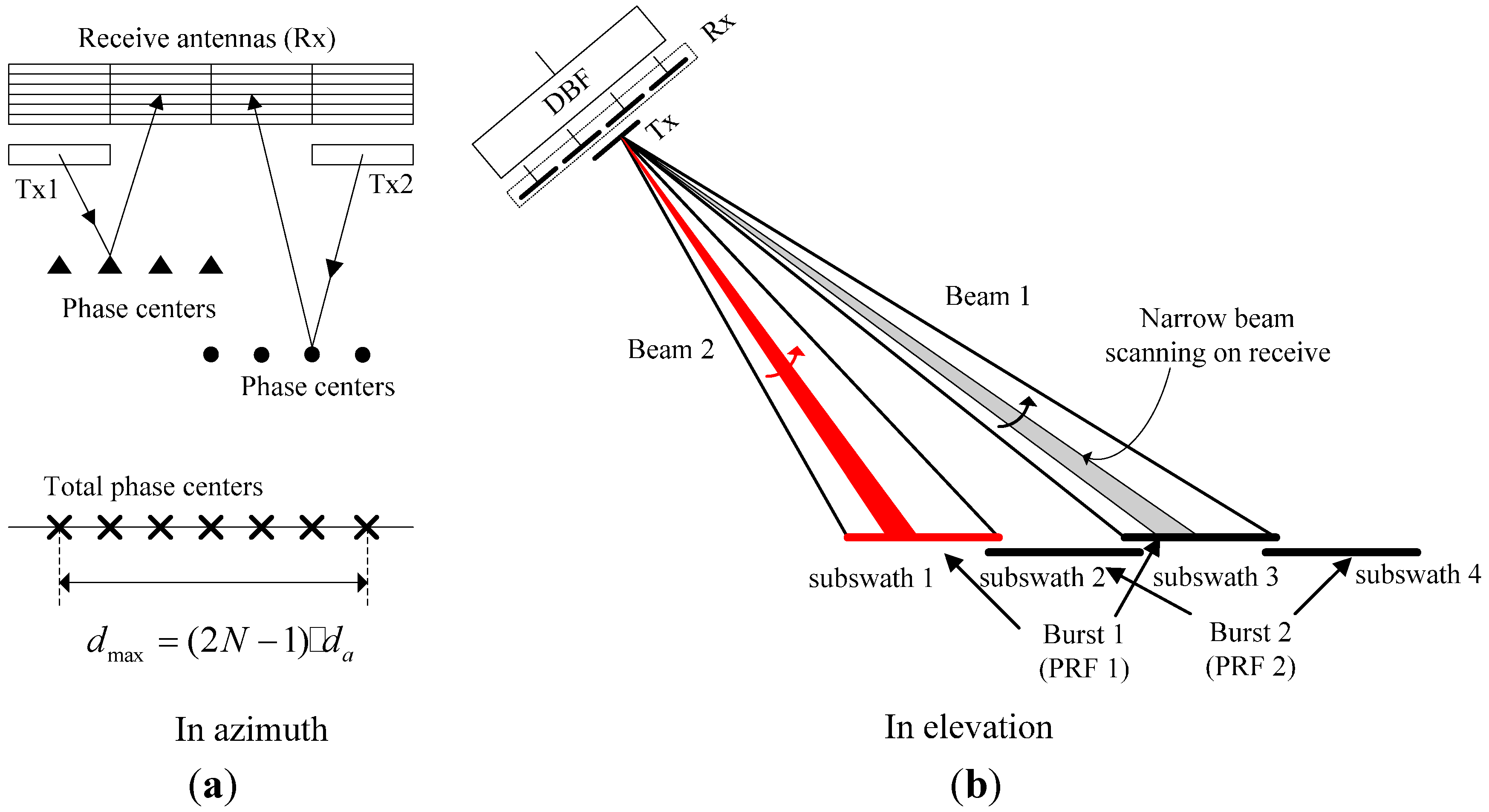
3. Signal Processing
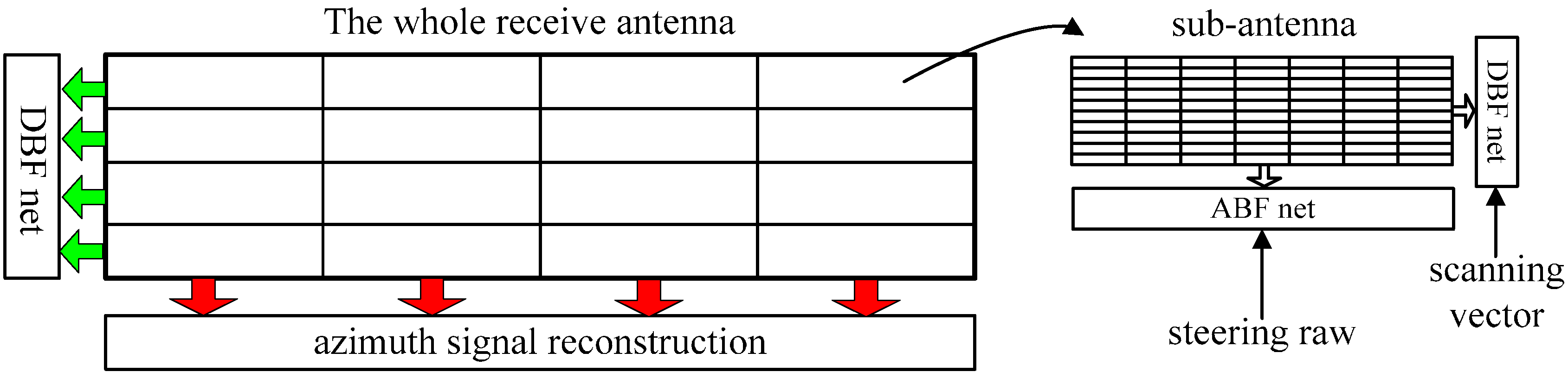
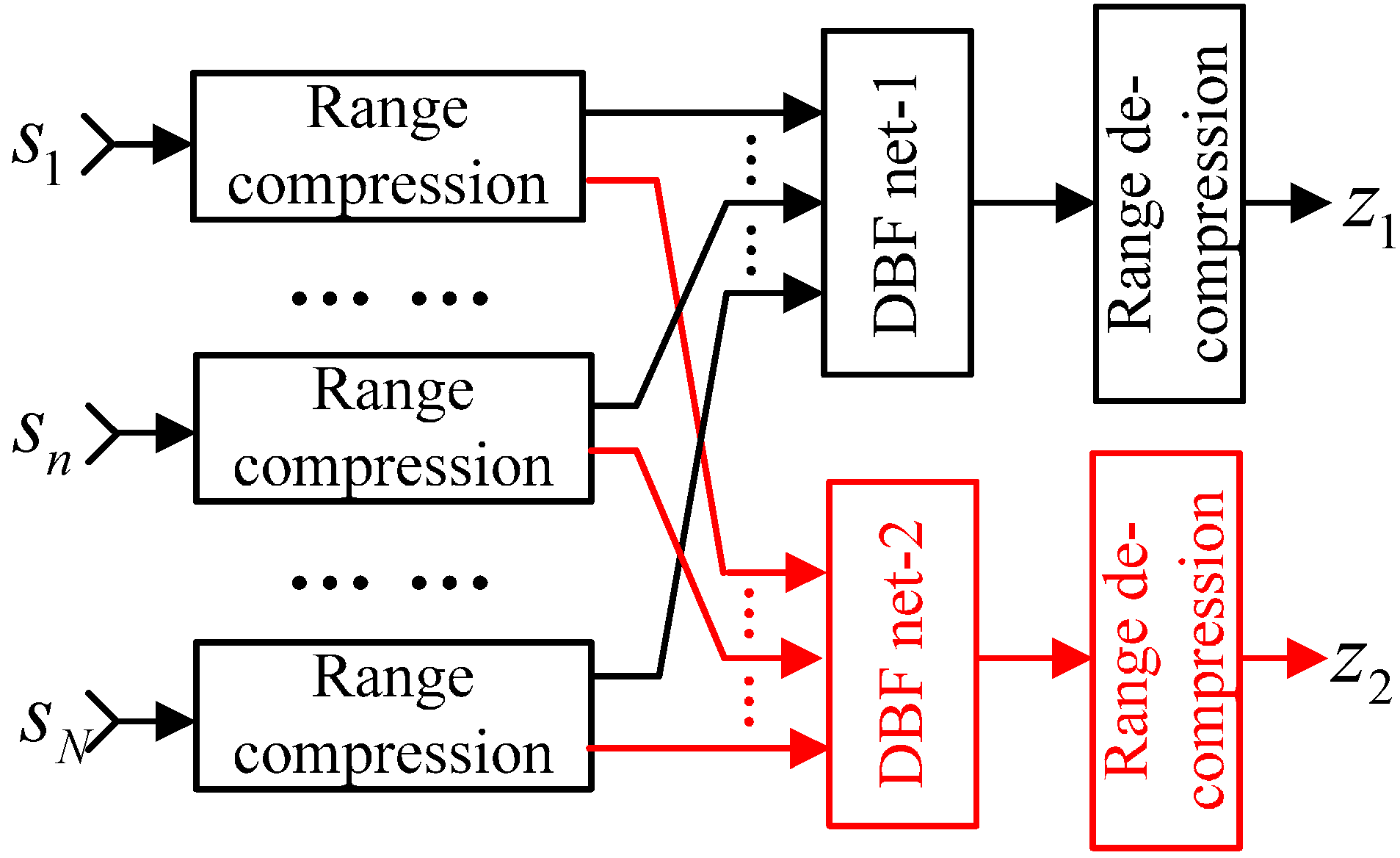
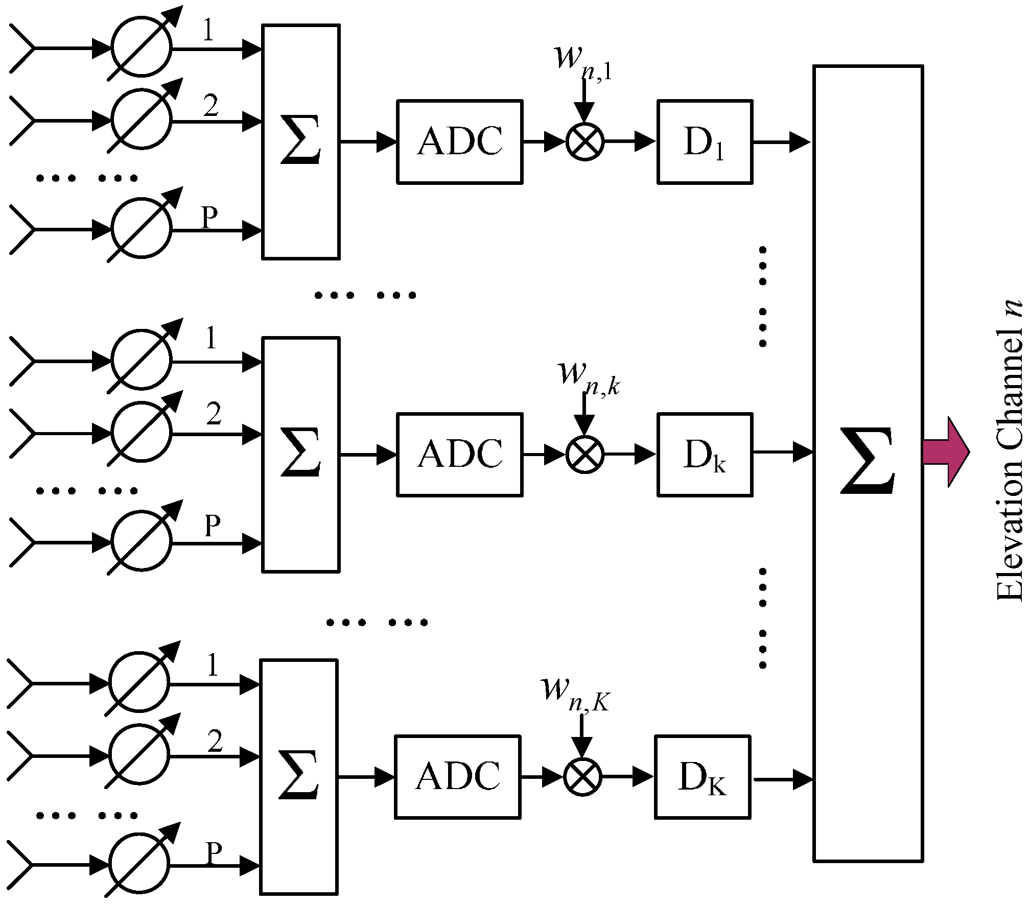
3.1. DBF on Receive for Each Sub-Array in Elevation

| Parameters | Value |
|---|---|
| Carrier frequency | 9.65 GHz |
| Sensor height (over earth) | 630 km |
| Sensor velocity | 7545 m/s |
| Incident angle range | 18°~50° |
| Transmit sub-antenna size | 2.4 m × 0.3 m |
| Transmit sub-antenna T/R elements | 24 × 15 |
| Azimuth receive antenna length | 9.6 m |
| Azimuth receive sub-antennas | 4 |
| Peak Tx Power | 2880 W |
| System temperature | 300 K |
| Pulse duration | 40 μs |
| Pulse bandwidth | 100 MHz |
| Sampling frequency | 120 MHz |
| Noise figure and system losses | 5.7 dB |
| Boltzmann constant | 1.38 × 10⁻²³ J/K |
| RASR, AASR | <−24 dB |
| NEσ° | <−20 dB |
| BAQ | 8:3 |
| Operation time in a single orbit | 200 s |
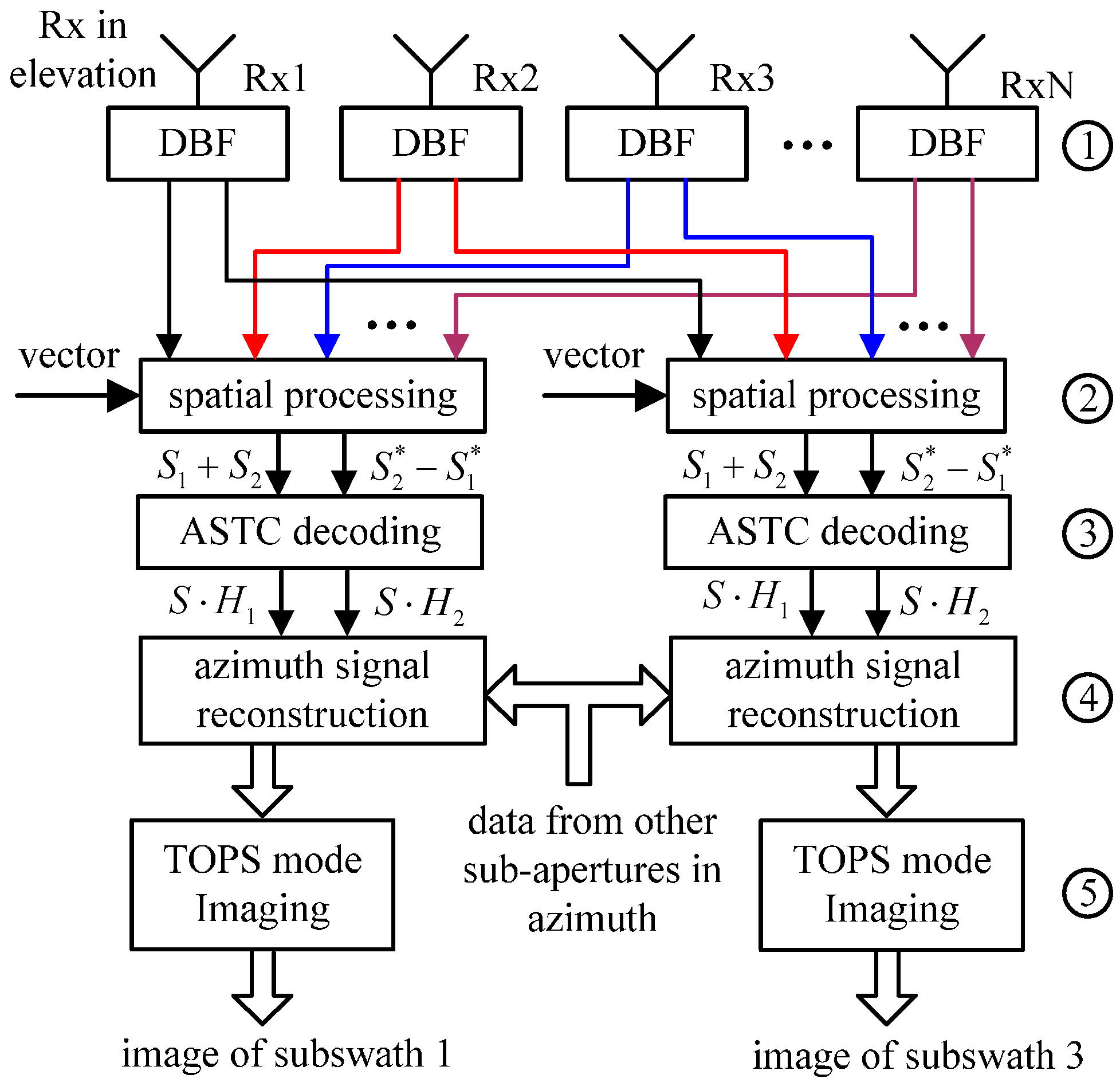
3.2. Spatial Processing in Elevation

3.3. ASTC Decoding
3.4. Azimuth Signal Reconstruction
3.5. Monostatic TOPS SAR Imaging
4. System Example
4.1. System Example

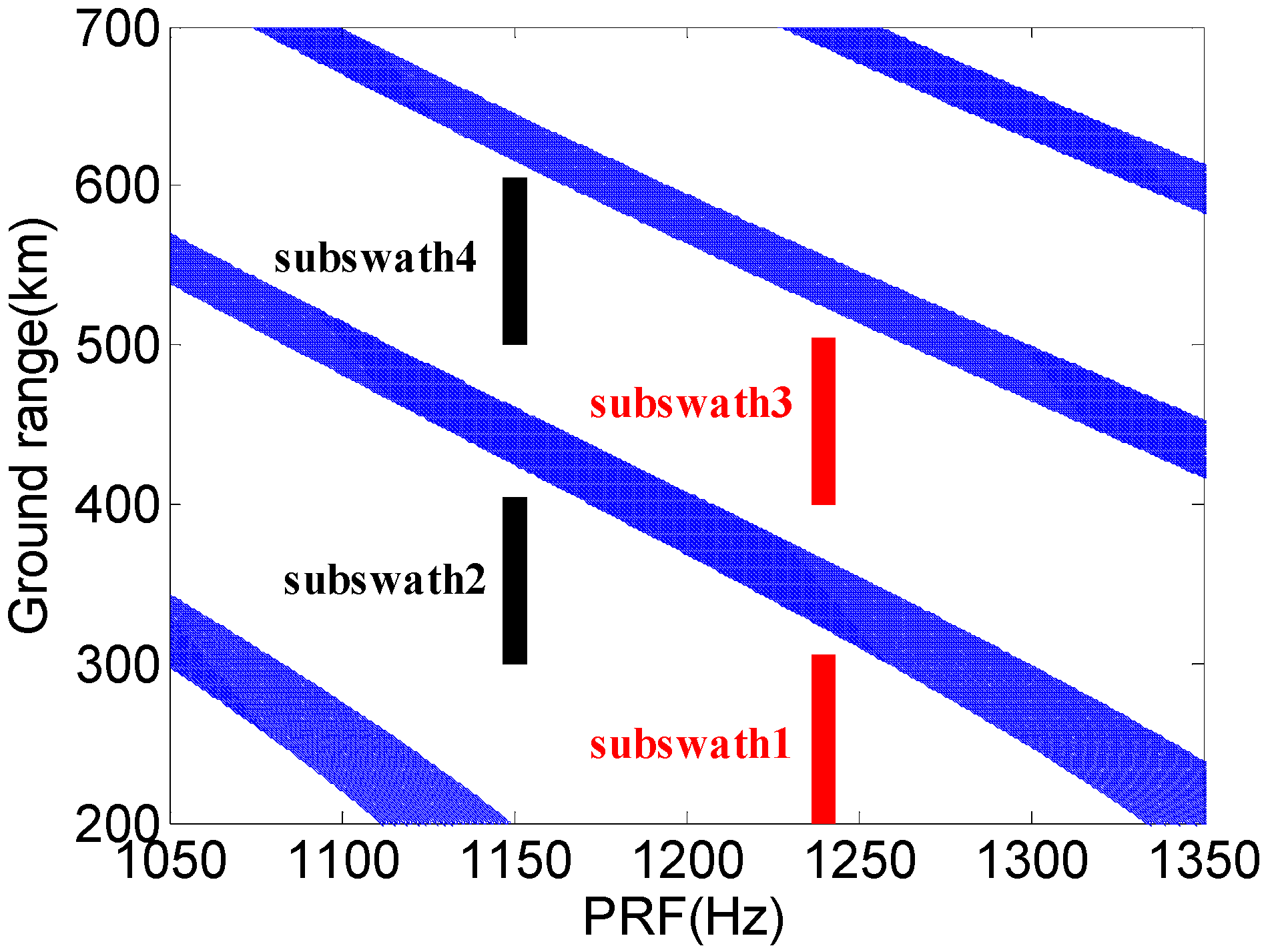
| Swath 1 | Swath 2 | Swath 3 | Swath 4 | |
|---|---|---|---|---|
| Incident angle (°) | 19.3–28.3 | 27.5–35.5 | 35.1–42.1 | 41.7–47.7 |
| PRF(Hz) | 1240 | 1150 | 1240 | 1150 |
| Slant range (km) | 681.8 | 726.6 | 783.9 | 850.2 |
| Swath depth (km) | 105 | 105 | 105 | 100 |
| Burst duration (s) | 2.09 | 2.13 | 2.09 | 2.13 |
| Rotation rate (°/s) | 0.88 | 0.81 | 0.88 | 0.81 |
| Date rate (Gbps) | 6.90 | 7.12 | 6.90 | 7.12 |
| AASR(dB) | −24.32 dB | −23.18 dB | −24.32 dB | −23.18 dB |
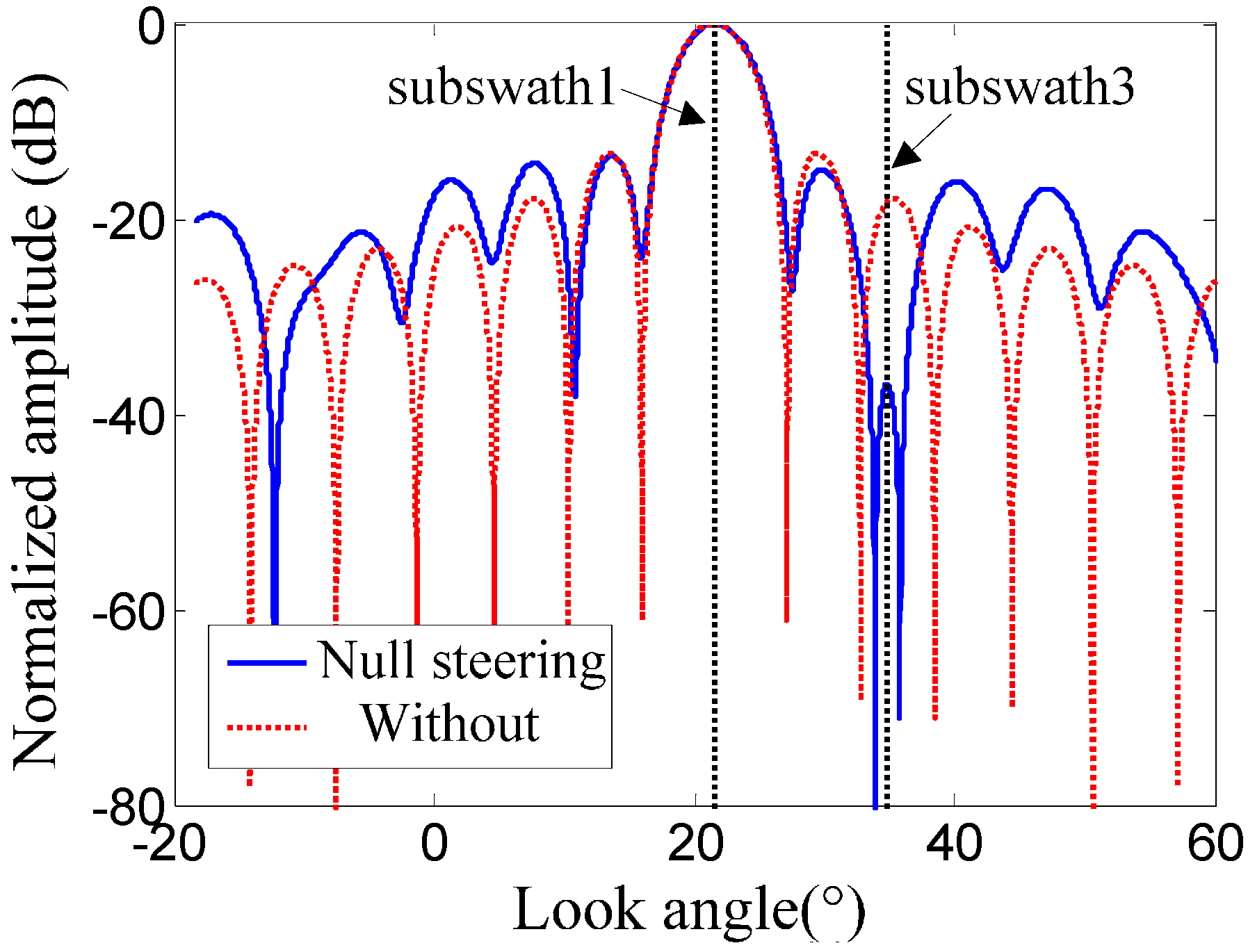
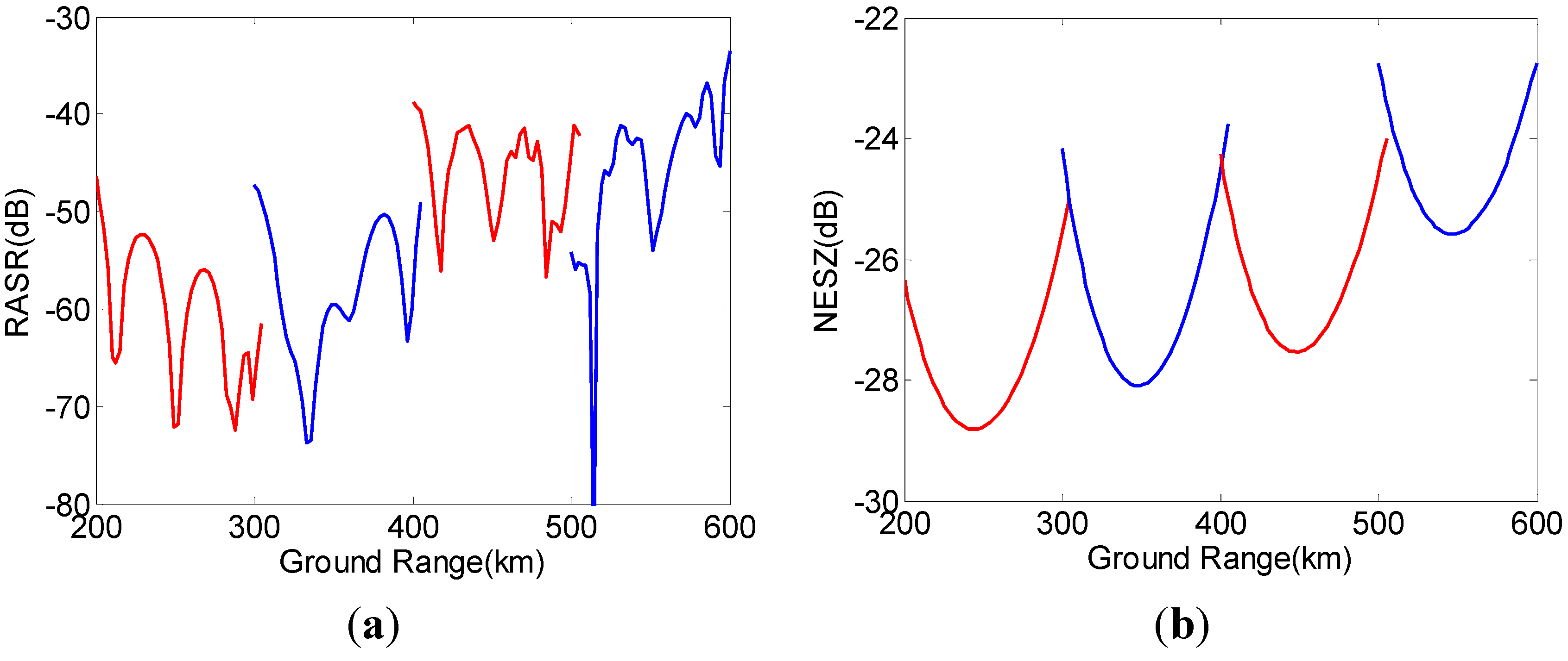
4.2. Performance Analysis

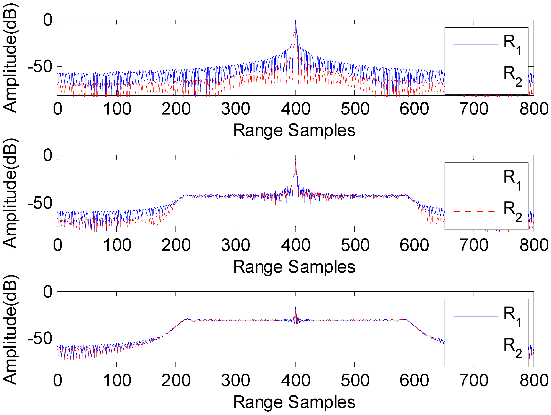
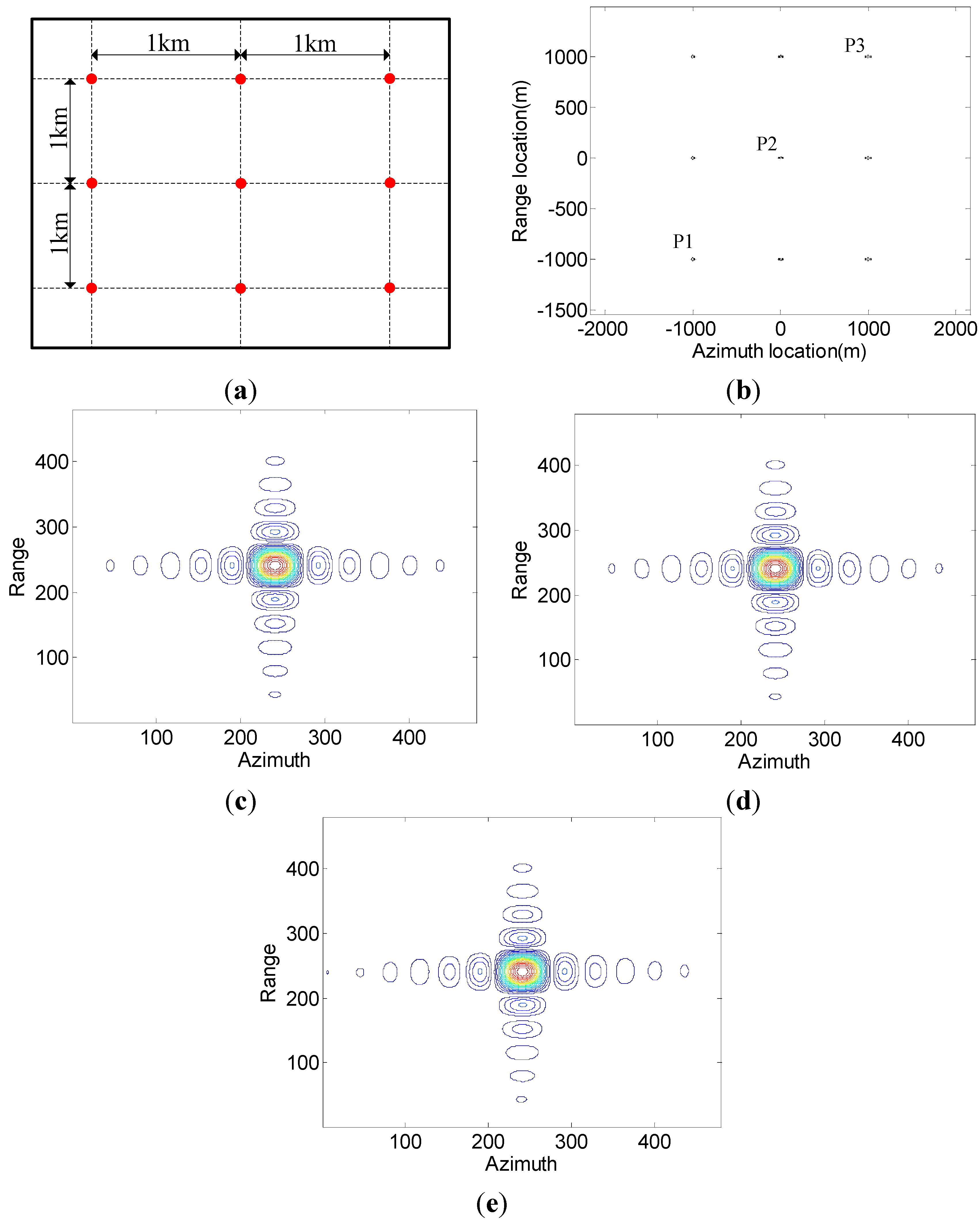
4.3. Imaging Simulation
| Azimuth | Range | |||||
|---|---|---|---|---|---|---|
| Resolution (m) | PSLR (dB) | ISLR (dB) | Resolution (m) | PSLR (dB) | ISLR (dB) | |
| Theoretical | 1.20 | 13.26 | 9.80 | 1.33 | 13.26 | 9.80 |
| P1 | 1.21 | 13.24 | 9.94 | 1.33 | 13.26 | 9.83 |
| P2 | 1.21 | 13.24 | 9.91 | 1.33 | 13.26 | 9.87 |
| P3 | 1.21 | 13.24 | 9.97 | 1.33 | 13.26 | 9.78 |
5. Conclusions
Acknowledgments
Author Contributions
Conflicts of Interest
References
- Currie, A.; Brown, M.A. Wide-swath SAR. IEEE Proc. F Radar Signal Process. 1992, 139, 123–135. [Google Scholar] [CrossRef]
- Freeman, A.; Johnson, W.T.K.; Huneycutt, B.; Jordan, R.; Hensley, S.; Siqueira, P.; Curlander, J.C. The “myth” of the minimum SAR antenna area constraint. IEEE Trans. Geosci. Remote Sens. 2000, 38, 320–324. [Google Scholar] [CrossRef]
- Holzner, J.; Bamler, R. Burst-mode and ScanSAR interferometry. IEEE Trans. Geosci. Remote Sens. 2002, 40, 1917–1934. [Google Scholar] [CrossRef]
- De Zan, F.; Monti Guarnieri, A. TOPSAR: Terrain observation by progressive scans. IEEE Trans. Geosci. Remote Sens. 2006, 44, 2352–2360. [Google Scholar]
- Prats, P.; Scheiber, R.; Mittermayer, J.; Meta, A.; Moreira, A. Processing of sliding spotlight and TOPS SAR data using baseband azimuth scaling. IEEE Trans. Geosci. Remote Sens. 2010, 48, 770–780. [Google Scholar] [CrossRef]
- Meta, A.; Mittermayer, J.; Prats, P.; Scheiber, R.; Steinbrecher, U. TOPS imaging with TerraSAR-X: Mode design and perfomance analysis. IEEE Trans. Geosci. Remote Sens. 2010, 48, 759–769. [Google Scholar] [CrossRef] [Green Version]
- Belcher, D.P.; Baker, C.J. High resolution processing of hybrid stripmap/spotlight mode SAR. IEE Proc. Radar Sonar Navig. 1996, 143, 366–374. [Google Scholar] [CrossRef]
- Xu, W.; Deng, Y.; Wang, R. Multichannel synthetic aperture radar systems with a planar antenna for future spaceborne microwave remote sensing. IEEE Aerosp. Electron. Syst. Mag. 2012, 46, 26–30. [Google Scholar] [CrossRef]
- Junghyo, K.; Alicja, O.; Werner, W. Investigation of MIMO SAR for interferometry. In Proceedings of the European Conference on Synthetic Aperture Radar (EUSAR), Munich, Germany, 10–12 October 2007.
- Krieger, G.; Gebert, N.; Moreira, A. Multidimensional waveform encoding: A new digital beamforming technique for synthetic aperture radar remote sensing. IEEE Trans. Geosci. Remote Sens. 2012, 46, 31–46. [Google Scholar] [CrossRef]
- Wang, W.-Q. Space-time coding MIMO-OFDM SAR for high-resolution imaging. IEEE Trans. Geosci. Remote Sens. 2011, 49, 3094–3104. [Google Scholar] [CrossRef]
- Wang, W.-Q. Virtual antenna array analysis for MIMO synthetic aperture radars. Int. J. Antennas Propag. 2012, 2012. [Google Scholar] [CrossRef]
- Wang, W.-Q. Mitigating range ambiguities in high-PRF SAR with OFDM waveform diversity. IEEE Trans. Geosci. Remote Sens. 2013, 10, 101–105. [Google Scholar] [CrossRef]
- Christallini, D.; Pastina, D.; Lombardo, P. Exploiting MIMO SAR potentialities with efficient cross-track constellation configurations for improved range resolution. IEEE Trans. Geosci. Remote Sens. 2011, 49, 38–52. [Google Scholar] [CrossRef]
- Gebert, N.; Krieger, G.; Younis, M.; Bordoni, F.; Moreira, A. Ultra wide swath imaging with multi-channel ScanSAR. In Proceedings of the IEEE International Geoscience and Remote Sensing Symposium, Booston, MA, USA, 7–11 July 2008.
- Suess, M.; Grafmueller, B.; Zahn, R. A novel high resolution, wide swath SAR system. In Proceedings of the IEEE International Geoscience and Remote Sensing Symposium (IGARSS), Sydney, NSW, Australia, 9–13 July 2001; pp. 1013–1015.
- Suess, M.; Wiesbeck, W. Side-Looking Synthetic Aperture Radar System. EP 1 241 487, 18 September 2002. [Google Scholar]
- Krieger, G.; Gebert, N.; Moreira, A. Digital beamforming techniques for spaceborne radar remote sensing. In Proceedings of the European Conference on Synthetic Aperture Radar (EUSAR), Dresden, Germany, 16–18 May 2006.
- Krieger, G.; Gebert, N.; Moreira, A. Unambiguous SAR signal reconstruction from nonuniform displaced phase center sampling. IEEE Trans. Geosci. Remote Sens. 2004, 1, 260–264. [Google Scholar] [CrossRef]
- Li, Z.; Wang, H.; Su, T.; Bao, Z. Generation of wide-swath and high-resolution SAR images from multichannel small spaceborne SAR systems. IEEE Geosci. Remote Sens. Lett. 2005, 2, 82–86. [Google Scholar] [CrossRef]
- Younis, M.; Fischer, C.; Wiesbeck, W. Digital beamforming in SAR systems. IEEE Trans. Geosci. Remote Sens. 2003, 41, 1735–1739. [Google Scholar] [CrossRef]
- Gebert, N.; Krieger, G.; Moreira, A. Digital beamforming on receive: Techniques and optimization strategies for high-resolution wide-swath SAR imaging. IEEE Trans. Aerosp. Electron. Syst. 2009, 45, 564–592. [Google Scholar] [CrossRef]
- Xu, W.; Huang, P.; Wang, R.; Deng, Y. Processing of multichannel sliding spotlight and TOPS synthetic aperture radar data. IEEE Trans. Geosci. Remote Sens. 2013, 51, 4417–4429. [Google Scholar] [CrossRef]
- Xu, W.; Huang, P.; Deng, Y. MIMO-TOPS mode for high-resolution ultra-wide-swath full polarimetric imaging. Prog. Electromagn. Res. 2011, 121, 19–37. [Google Scholar] [CrossRef]
- Xu, W.; Huang, P.; Deng, Y.; Sun, J.; Shang, X. An efficient approach with scaling factors for TOPS-mode SAR data focusing. IEEE Geosci. Remote Sens. Lett. 2011, 8, 929–933. [Google Scholar] [CrossRef]
- Xu, W.; Huang, P.; Deng, Y. TOPSAR data focusing based on azimuth scaling preprocessing. Adv. Space Res. 2011, 48, 270–277. [Google Scholar] [CrossRef]
© 2015 by the authors; licensee MDPI, Basel, Switzerland. This article is an open access article distributed under the terms and conditions of the Creative Commons Attribution license (http://creativecommons.org/licenses/by/4.0/).
Share and Cite
Huang, P.; Xu, W. ASTC-MIMO-TOPS Mode with Digital Beam-Forming in Elevation for High-Resolution Wide-Swath Imaging. Remote Sens. 2015, 7, 2952-2970. https://0-doi-org.brum.beds.ac.uk/10.3390/rs70302952
Huang P, Xu W. ASTC-MIMO-TOPS Mode with Digital Beam-Forming in Elevation for High-Resolution Wide-Swath Imaging. Remote Sensing. 2015; 7(3):2952-2970. https://0-doi-org.brum.beds.ac.uk/10.3390/rs70302952
Chicago/Turabian StyleHuang, Pingping, and Wei Xu. 2015. "ASTC-MIMO-TOPS Mode with Digital Beam-Forming in Elevation for High-Resolution Wide-Swath Imaging" Remote Sensing 7, no. 3: 2952-2970. https://0-doi-org.brum.beds.ac.uk/10.3390/rs70302952