Article

Multispectral Radiometric Analysis of Façades to Detect Pathologies from Active and Passive Remote Sensing

by
Susana Del Pozo
1,*,
Jesús Herrero-Pascual
1,
Beatriz Felipe-García
2,
David Hernández-López
2,
Pablo Rodríguez-Gonzálvez
1 and
Diego González-Aguilera
1
1
Department of Cartographic and Land Engineering, University of Salamanca, Hornos Caleros, 05003 Ávila, Spain
2
Institute for Regional Development (IDR), Albacete, University of Castilla La Mancha, 02071 Albacete, Spain
*
Author to whom correspondence should be addressed.
Submission received: 18 September 2015 / Revised: 11 January 2016 / Accepted: 18 January 2016 / Published: 21 January 2016

Abstract

:
This paper presents a radiometric study to recognize pathologies in façades of historical buildings by using two different remote sensing technologies covering part of the visible and very near infrared spectrum (530–905 nm). Building materials deteriorate over the years due to different extrinsic and intrinsic agents, so assessing these affections in a non-invasive way is crucial to help preserve them since in many cases they are valuable and some have been declared monuments of cultural interest. For the investigation, passive and active remote acquisition systems were applied operating at different wavelengths. A 6-band Mini-MCA multispectral camera (530–801 nm) and a FARO Focus3D terrestrial laser scanner (905 nm) were used with the dual purpose of detecting different materials and damages on building façades as well as determining which acquisition system and spectral range is more suitable for this kind of studies. The laser scan points were used as base to create orthoimages, the input of the two different classification processes performed. The set of all orthoimages from both sensors was classified under supervision. Furthermore, orthoimages from each individual sensor were automatically classified to compare results from each sensor with the reference supervised classification. Higher overall accuracy with the FARO Focus3D, 74.39%, was obtained with respect to the Mini MCA6, 66.04%. Finally, after applying the radiometric calibration, a minimum improvement of 24% in the image classification results was obtained in terms of overall accuracy.

Graphical Abstract

1. Introduction

Historical buildings and monuments are valuable constructions for the area where they are placed. The degradation of their construction materials is caused mainly by environmental factors such as pollution and meteorological conditions. Specifically, the presence of water plays an important role in stone deterioration processes [1]. It accelerates the weathering processes contributing to dissolution and frost/thaw cycles among others [2] allowing the formation of black crust on the rock surface resulting in mechanical and chemical degradations of stones. For that reason the use of non-contact and non-destructive technologies to study stone damages is important for the preservation of buildings and for the choice of the best technique for restoration [3,4].
Terrestrial laser scanners and multispectral digital cameras are two different technologies that are suitable for these studies. They are non-destructive and non-invasive sensors that allow researchers to acquire massive geometric and radiometric information across the building with high accuracy and in a short acquisition time. The geometrical information provided by laser scanner technology has been successfully applied in a large number of fields such as archaeology [5], civil engineering [6], geology [7] and geomorphological analysis [8]. On the other hand, radiometric information, provided by the laser intensity data and the multispectral digital cameras, is used less frequently. Even so, its high potential for classification tasks and recognition of different materials has been demonstrated [9]. Nowadays, in the literature, one can find works related to this issue ranging from methodologies of radiometric calibration [10] to corrections of intensity values [9,11] including applications of the intensity data [12]. Spectral classification methods are based on the properties of the reflected radiation from each surface and the fact that each specific material has wavelength dependent reflection characteristics. There are many classification methods, which vary in complexity. These methods include hard and soft classifiers, parametric and non-parametric methods and supervised and unsupervised techniques [13]. There are several works related to the application of these techniques to the identification of damage on building surfaces [14,15,16,17,18].
The main objective of this paper is the classification and mapping of pathologies and materials of a historical building façade from reflectance values at different wavelengths by combining intensity calibrated data from a FARO Focus3D laser scanner and calibrated images from a 6-band Mini-MCA multispectral camera. Additional goals were evaluating the degree of automation in the pathology detection process of façades. To achieve these objectives, the paper is divided into the following sections: Section 2 gives the details and specifications of the equipment employed and thoroughly describes the methods employed in the workflow methodology. Section 3 shows the classification maps and accuracy results for both unsupervised and supervised classifications, closing with Section 4 which summarizes the main conclusions and findings drawn from the study.

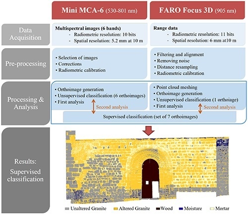
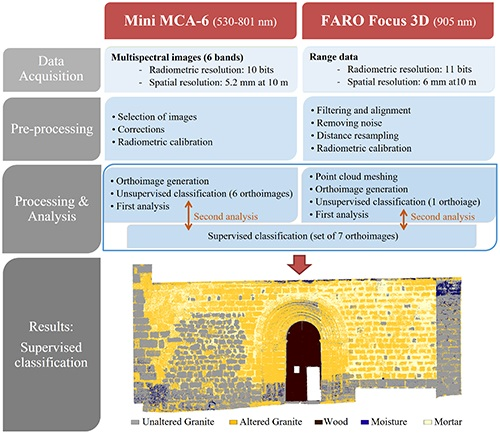
2. Material and Methods
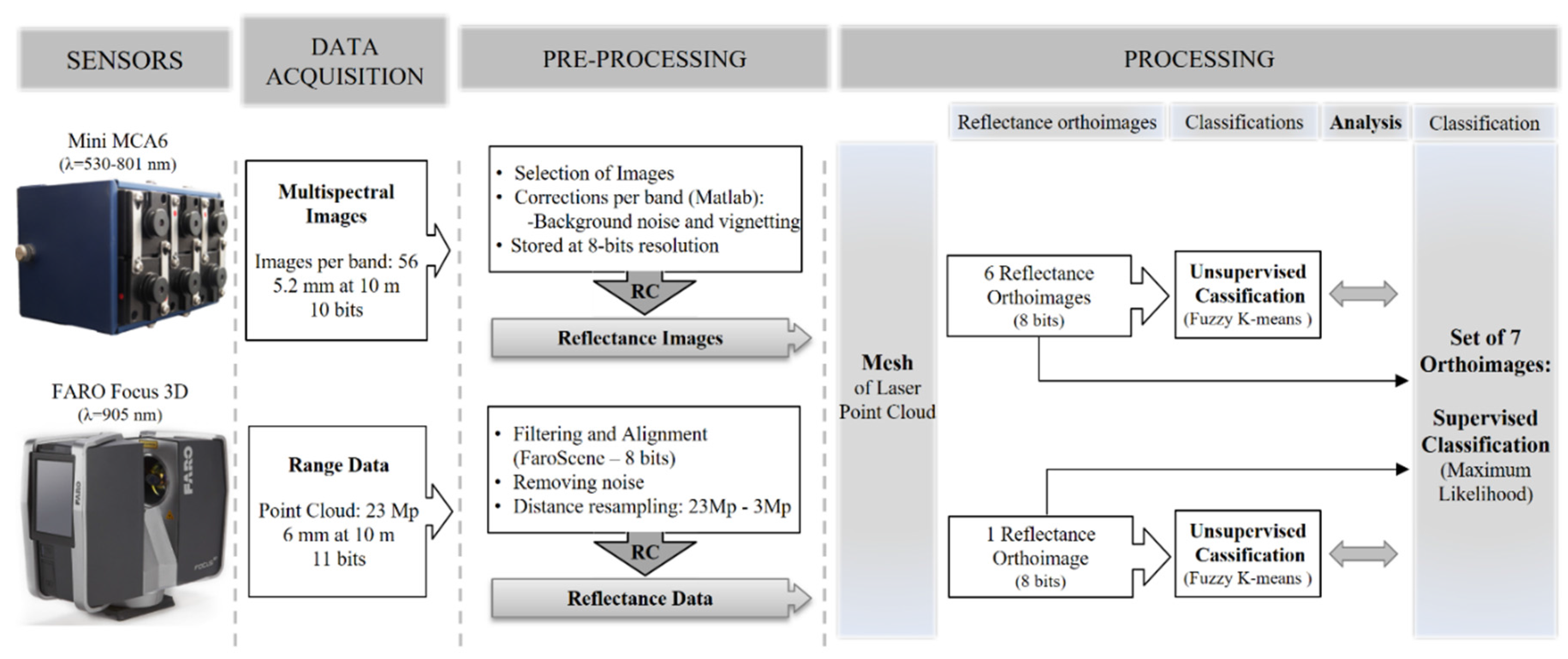
The methodology developed to reach the objectives of the paper consists of three main stages: the data acquisition, the pre-processing and the processing of data as is outlined in Figure 1. For the data acquisition, two sensors with different operating principles were implemented: a passive multispectral camera and an active terrestrial laser scanner. The pre-processing step involved data filtering and several corrections applied to the spectral information to finally obtain data in reflectance values. During the last step and taking advantage of the metrics from the scan points, reflectance orthoimages were generated for both the multispectral images and the laser intensity. These orthoimages were the input for two different classifications processes: a clustering classification with data from each sensor and a supervised classification with the set of all data from both sensors.
Figure 1. The workflow of the methodology presented. Acronyms: RC = Radiometric calibration and Mp = Millions of points.
Remotesensing 08 00080 g001

2.1. Equipment

For the documentation of the façade, the following equipment was used: two radiometrically calibrated sensors with different characteristics and data acquisition principles, a passive multispectral camera and an active terrestrial laser scanner. Figure 1 shows the main characteristics of them and the different stages of the workflow followed in this research.
For the multispectral data acquisition, a calibrated lightweight Multiple Camera Array (MCA-Tetracam) was employed. This low-cost sensor allows versatility in data acquisition; however it requires the radiometric and geometric corrections to ensure the quality of the results [19]. It includes a total of 6 individual sensors with filters for the visible and near infrared spectrum data acquisition. More specifically, the individual bands of 530, 672, 700, 742, 778 and 801 nm were used. The longest wavelength was chosen taking into account that the multispectral sensor is not externally cooled. In spite of its 1280 × 1024 pixels of image resolution, the camera has a radiometric resolution of 10 bits. The focal length of 9.6 mm and the pixel size of 5.2 µm yield a façade sample distance (FSD) of 5.4 mm for a distance of 10 m, which should be taken into account for the pathology detection performance in small elements. The main limitation of this camera is the field of view (38° × 31°), so several captures were needed to keep the FSD.
The FARO Focus3D is a phase shift continuous wave terrestrial laser scanner (TLS) operating at a wavelength of 905 nm. It is not common to use this kind of sensor to perform radiometric studies but it guarantees a comprehensive data acquisition whose results are not influenced by changes in light. This device measures distances in a range of 0.60–120 m with a point measurement rate of 976,000 points per second. It has an accuracy of 0.015° in normal lighting and reflectivity conditions and a beam divergence of 0.19 mrad, equivalent to 19 mm per 100 m range. The field of view covers 320° vertically and 360° horizontally with a 0.009° of angular resolution and the returning intensity is recorded at 11 bits. This laser scanner includes, in addition, a double compensator in the horizontal and vertical axis that can be used as constraint for the scan alignment.
Additionally, a high resolution spectroradiometer (ASD FieldSpec3) (Figure 2) was used as a remote detector of radiant intensity from the visible to the shortwave infrared ranges (350 to 2500 nm with a maximum spectral resolution of 3 nm and ±1 nm wavelength accuracy) to validate the spectral results of the study [20]. Equipped with optical fiber cables, it measured reflectances from the different materials and covers of the façade with a 25° field of view. Measures were made by positioning the spectroradiometer gun (Figure 2a) as orthogonal as possible and at a distance of approximately 10 cm from the sample, trying to cover a relatively homogeneous area of the material.
Figure 2. ASD FieldSpec3 spectroradiometer collecting spectral radiation reflected from (a) the Spectralon target and (b) mortar between contiguous stones of the examined façade.
Remotesensing 08 00080 g002

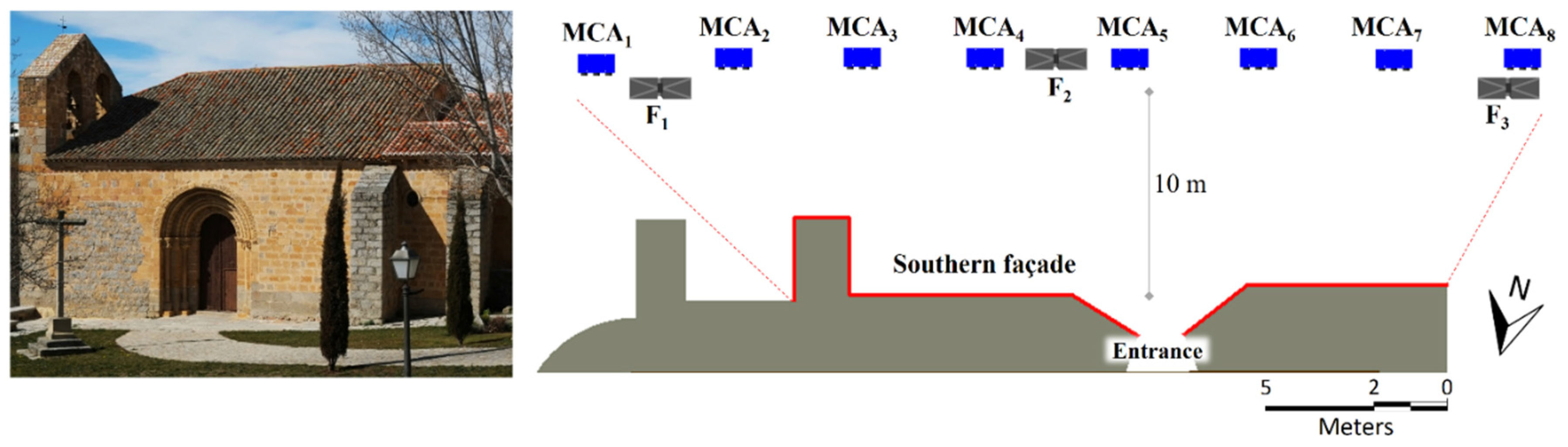
2.2. Data Acquisition

Since each material has a unique reflectance behavior depending of the wavelength, the presence of pathologies on façades, such as moisture, moss or efflorescence, is likely to be successfully detected by analyzing the reflected visible and very near infrared radiation from the façades in reflectance values instead of digital levels (output digital format of the device). That is why these two sensors were radiometrically pre-calibrated and used to obtain orthoimages with surface reflectance values instead of digital levels. Since reflectance, for the specific case of a passive sensor, is a function of the solar incident radiance, a standard calibrated reflection target (Spectralon, Labsphere) was required and placed on the façade (Figure 2a), thus it appeared in every multispectral image to be able to calculate the solar irradiance (E) of each capture moment.
Illumination is a crucial parameter for data acquisition with passive sensor, particularly when several shot positions are required to cover the object of study. For that reason and to ensure the greatest resolution, taking fewer photos as far as possible was prioritized in this study. A total of 56 captures were collected with a FSD of 5.4 mm for the worst case so that the standard calibrated reflection target appeared in all of them.
On the other hand, the laser scanner data acquisition was designed so that the effect of the laser beam incidence angle [21,22] was minimized. Intensity data at 11-bit resolution was collected at an average distance of 10 m through three scans with scan area restrictions. Thus, 7 m of façade were covered for each of the scans assuming a maximum incidence angle error of 5.6% regarding the maximum oblique angle of incidence (19.29°). In addition, scanning positions were selected according to the different technical specifications of the scanner for an spatial resolution of 6 mm at the working distance. The laser network was adapted and filtered due to the presence of obstacles that hinder a single station data acquisition.

2.3. Pre-Processing

Before the reflectance orthoimage generation some corrections to raw data were applied to avoid error propagation in the radiometric calibration process. In this section, these radiometric corrections and the final radiometric calibration were described as well as the orthoimages generation process. Finally, the orthoimages were classified to obtain maps of different pathologies and building materials.

2.3.1. Multispectral Images Corrections

Low-cost sensors, such as the Mini MCA6, are more likely to be affected by different noise sources so that the actual value of radiation collected by them is altered (Equation (1)) [23]. Specifically, the Mini MCA6 was affected by two different sources errors: a background noise and a vignetting effect [20]. Both errors were studied under precise laboratory controlled conditions for each wavelength band.
The background noise is a systematic error caused by the sensor electronics of the camera. It was analyzed in a completely dark room in the absence of light determining the noise per band depending on the exposure time. For this study, the maximum background error was for the 801-nm band and involved a 1.07% increment of the actual digital level value. Regarding the vignetting effect [24], the radial attenuation of the brightness was studied taking images of a white pattern with uniform lighting conditions. Digital levels of each multispectral image were corrected for these two effects through a script developed in Matlab to improve the data quality before the radiometric calibration.
D L r a w = D L r a d i a n c e + ( D L b n + D L v )
where DLraw are the digital levels of the raw images, DLradiance are the digital levels from the radiance component, DLbn are the digital levels from background noise and DLv are the digital levels from the vignetting component.

2.3.2. Filtering and Alignment of the Point Clouds

The raw laser scanner data were filtered and segmented in order to remove those points that were not part of the object of study (adjacent building, artificial elements, trees, etc.). The individual point cloud alignment was done by a solid rigid transformation by the use of external artificial targets (spheres). The spheres were stationed in tripods at the plumb-line plane surveyed by the global navigation satellite system (GNSS). The laser local coordinate system could be transformed to a global coordinate system (UTM30N in ETRS89), allowing the geo-referencing of the subsequent classification for a global analysis and interpretation. This proposed workflow allowed a final relative precision of the coordinates of the artificial targets of 0.01 m and an absolute error of 0.03 m after post-processing. As a result, a unique point cloud in a local coordinate system with 11 mm precision (due to the error propagation of inherent error sources of laser scanner [25] and the error associated to the definition of the coordinate system) was generated.

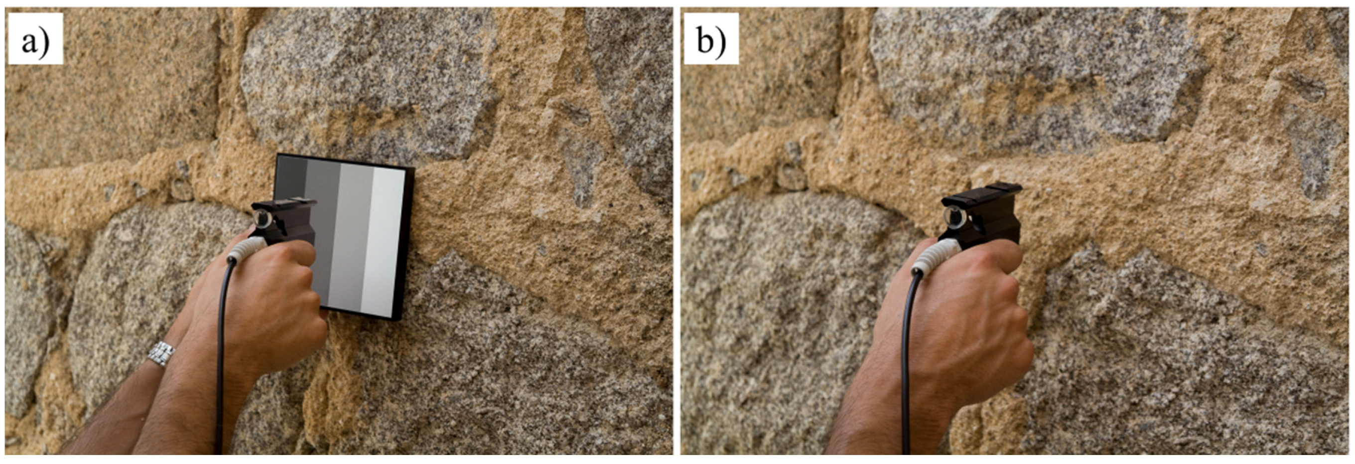
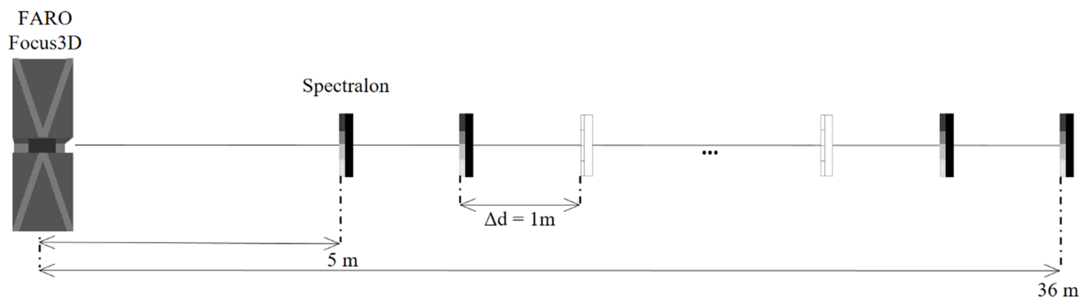
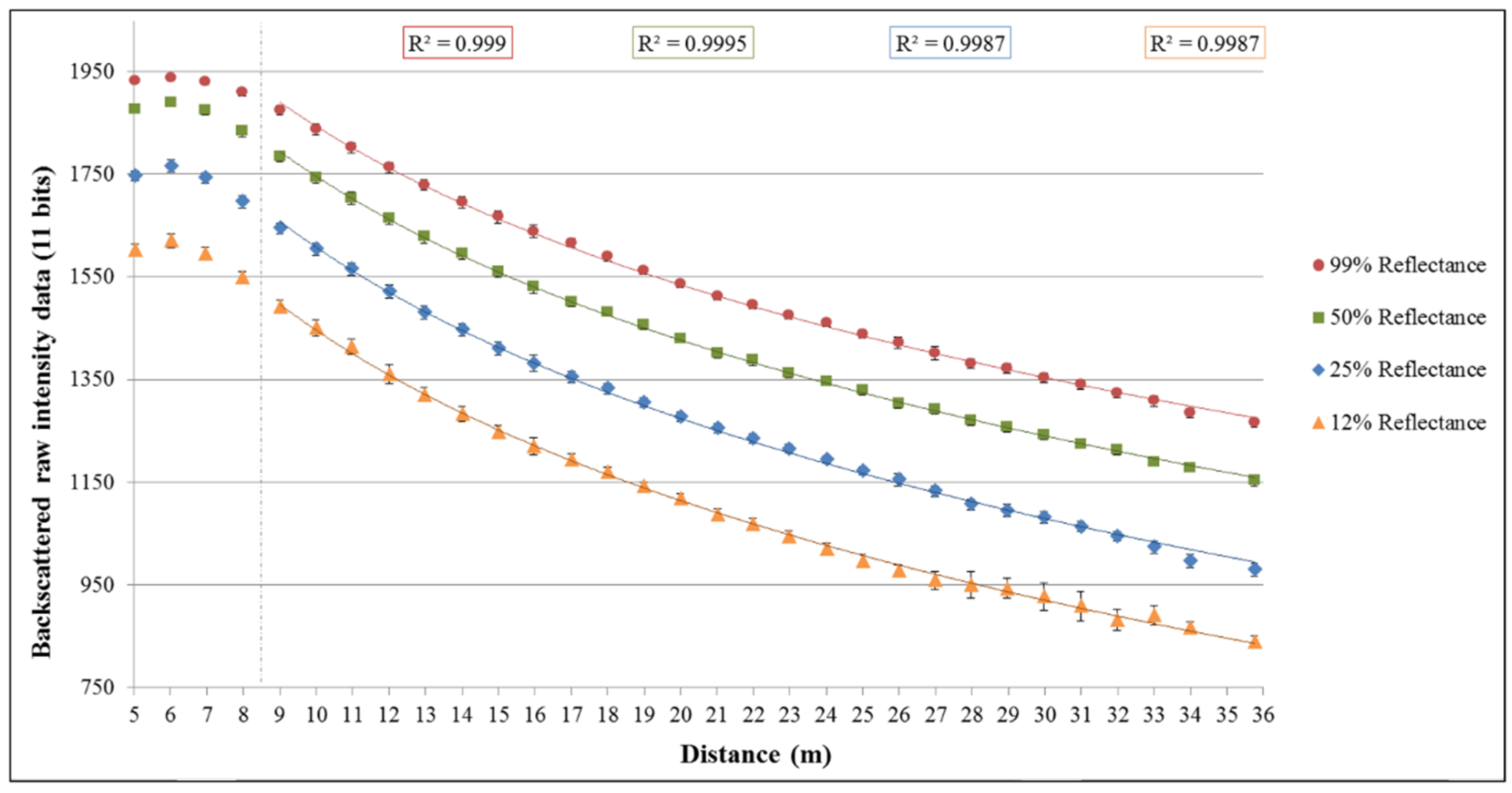
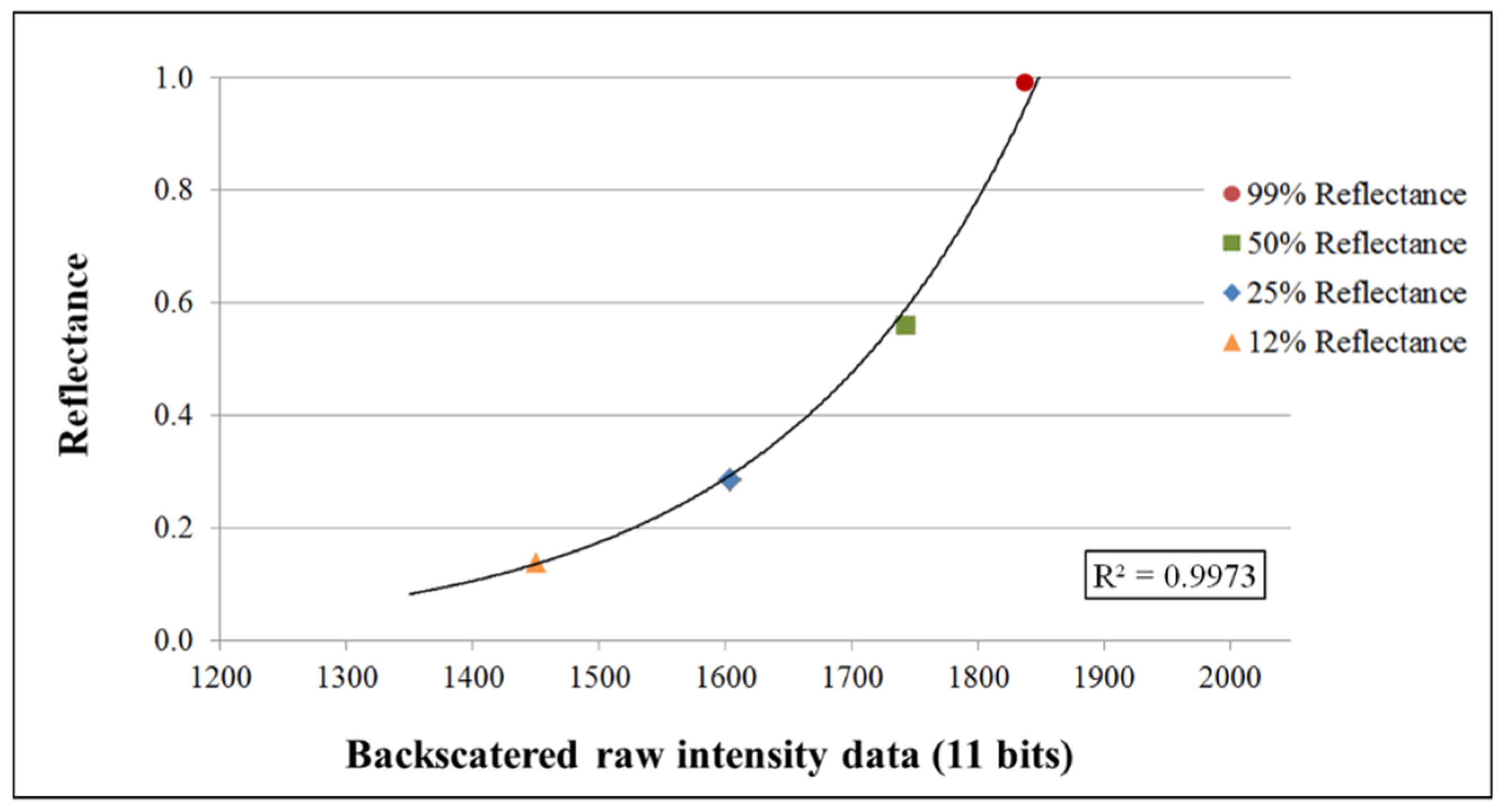
2.3.3. Radiometric Calibrations

To perform the radiometric calibration of both sensors, auxiliary equipment such as lambertian surfaces with known spectral behavior (Spectralon) and/or a spectroradiometer are needed to solve the calibration. Thus, after the calibration process images values, in the case of the camera, and points’ intensities, in the case of the laser scanner, correspond to the radiation emitted by the surface expressed in radiance or reflectance. The Mini MCA6 multispectral camera was calibrated in a previous field campaign [20] through in situ spectroradiometer measurements of artificial surfaces, with known and unknown reflectance behavior (Spectralon and polyvinyl chloride vinyl sheets respectively). Regarding the radiometric calibration of the TLS, it was carried out in laboratory by using a Spectralon and in absence of light.
The multispectral camera was calibrated by the radiance-based vicarious method [26,27,28], being the transformation equation from raw images into images with reflectances values Equation (2):
ρ M C A = c 0 λ + c 1 λ D L / F v λ E λ π
where c0λ and c1λ, offset and gain, are the calibration coefficients of each camera band, Fvλ the shutter opening time factor and Eλ the solar irradiance at the ground level. Table 1 summarizes the multispectral camera calibration coefficients and the R2 determination coefficient achieved per band.
Table 1. Calibration coefficients of the Mini MCA6 per band.
Bandsc0λc1λR2
530 nm0.0002640.0577180.9816
672 nm−0.0007950.0500050.9823
700 nm−0.0008610.0413530.9820
742 nm−0.0012050.0743350.9843
778 nm−0.0015100.0472920.9846
801 nm−0.0008340.0476560.9827
In order to obtain reflectance values directly from laser data, a reflectance-based radiometric calibration [28] consisting of analyzing the distance-behavior of the intensity data (Figure 3) was performed (Equation (3)).
ρ F A R O = e a d b d 2 e c 1 F D L F
where a and b were the empirical coefficients related to the signal attenuation and internal TLS conversion from the received power to the final digital levels, d the distance between the laser scanner and the object, c1F the gain of the TLS and DLF the raw intensity data in digital levels (11 bits). Please note that the empirical coefficients were obtained by a laboratory study, since the TLS internal electronics and intermediate signal processing is not disclosed.
In this case, a laboratory experiment from 5 to 36 m at one-meter intervals provided enough information to study the FARO Focus3D internal behavior (Figure 3). It was conducted in low-light conditions at a controlled temperature of 20 °C to model and simulate the system behavior. By positioning a Spectralon at each distance increment, intensity data were acquired at a quarter of the maximum resolution of the laser scanner (6 mm). The calibrated surface (Figure 2a) consists of four panels of 12%, 25%, 50% and 99% reflectance and it was assembled on a stable tripod to ensure its verticality. The raw intensity data from each reflectance panel were obtained by averaging the intensity values of the points belonging to each panel. The mean intensity value was plotted per panel and distance resulting in the Figure 4.
Figure 3. Sketch of the test performed to analyze the internal radiometric behavior of the FARO Focus3D.
Remotesensing 08 00080 g003
Figure 4. FARO Focus3D backscattered intensity behavior for the measurements of the four Spectralon panels at 1 m distance increments related to the signal attenuation (Equation (3)).
Remotesensing 08 00080 g004
Figure 4 shows the signal attenuation of the FARO Focus 3D with distance as well as the logarithmic model that the measurements follow for distances up to 9 m. This particular behavior was noted in previous research works with similar sensors [29] and it is explained by the lidar equation [30]. By knowing the calibrated reflectance values of each Spectralon panel for 905 nm, the wavelength of the laser scanner, field measurements could be related with these reflectance values at each studied distance. Being 0.992, 0.560, 0.287 and 0.139 the normalized (0–1) reflectance values for the panel of 99%, 50%, 25% and 12% of reflectance respectively. Figure 5 shows how these values relate at a 10 m distance, and follow an exponential relationship which is shown in Equation (3). This distance was chosen as a threshold since for lower distances the calibration model changes due to the internal measurement system, involving alternative mathematical models.
As Figure 4 shows, the greater the distance the greater the intensity errors in the measurements. This behavior is related to the decrease of the received power due to the distance attenuation and signal scattering. Since the effective range of the employed TLS is higher than the studied distance, this error only appears significantly in the lower reflectance surface (12% panel).
Figure 5. Relationship between TLS raw intensity data and reflectance for each spectralon panel at 10 m distance.
Remotesensing 08 00080 g005
Based on the empirical study of the laser response, the attenuation of the signal with the distance (Figure 4) and the logarithmic behavior of the sensor [29], the relationship between digital levels and reflectances was finally approximated according to the Equation (4).
ρ F A R O = e 0.214 d 3.907 10 - 7 d 2 e 0.005415 D L F
This empirical equation can be applied only to objects at a distance over than 8 m since as can be shown in Figure 4, the FARO Focus3D has a completely different behavior for shorter distances.

2.4. Processing

In this subsection reflectance products are joined to achieve the orthoimages at each wavelength and they are finally classified to obtain maps of different building materials and pathologies.

2.4.1. Orthoimages Generation

Once the final point cloud was filtered, aligned and calibrated, a triangulation was applied to create the digital façade model (DFM). This step was required in order to generate continue 2D products (in the form of true orthoimages) and carry out the pathology detection by the classification process. For the DSM generation the incremental triangulation Delaunay algorithm was applied [31]. The output was refined to avoid artifact, meshing gaps, and other errors [32].
Orthoimages are highly demanded products that offer many benefits: metric accuracy and radiometric information useful to analyze different information quantitatively and qualitatively.
For the orthoimage generation, it was necessary to know the external orientation of the images with respect to the coordinate system of the laser point cloud model. For that purpose an average of 20 corresponding points between the point cloud and images were manually established. The image projection was characterized by a rigid transformation (rotation and translation) together with the internal camera parameters.
Orthoimages were generated based on the anchor point method [33]. This method consists of applying an affine transformation to each one of the planes formed by the optimized triangular mesh, which was obtained from the point cloud determined by the laser. Through the collinearity condition [34], the pixel coordinates of the vertices of the mesh were calculated, and the mathematical model of the affine transformation directly relates the pixel coordinates of the registered image and of the orthoimage.

2.4.2. Orthoimages Classifications

In order to categorize the orthoimages in different informational classes a previous automatic unsupervised classification and a posterior supervised classification were performed. The unsupervised classification was based on the Fuzzy K-means clustering algorithm where each observation can concurrently belong to multiple clusters [35]. For a set of n multidimensional pixels, the automatic management in l clusters iteratively minimizes the Equation (5) [36]:
J m = i = 1 n l = 1 λ u m i , l x i c l 2 ;    1 m <
where m represents any real number greater than 1, xi the i-th of d-dimensional measured data, uil the degree of membership of xi in the cluster l, cl the d-dimensional center of the cluster and * * = Euclidean norm expressing the similarity between any measured data and the center.
Fuzzy partitioning is carried out through an iterative optimization of the objective function shown above, with the update of membership and the cluster centers by Equation (6).
u i l = 1 k = 1 c [ x i c l x i c k ] 2 m 1 ;    c l = i = 1 n u i l m x i i = 1 n u i l m
This iteration will stop when max i l { | u i l ( k + 1 ) u i l ( k ) | } < ε, where ε is the stop criterion between 0 and 1 and k represents the iteration steps.
After this classification, a first approach of the spectral classes and different construction materials was obtained. With a subsequently supervised classification and applying the expert knowledge of some classes, the final results improved. Furthermore, this supervised classification will serve as reference to discuss which sensor is the ideal one for detecting materials and pathologies in façades.
In this case, a maximum likelihood (ML) classification algorithm [37] was applied. The ML classifier quantitatively evaluates both the variance and covariance of the category spectral response patterns when classifying an unknown pixel. The resulting bell-shaped surfaces are called probability functions, and if the prior distributions of this function are not known, then it is possible to assume that all classes are equally probable. As a consequence, we can drop the probability in the computation of the discriminant function F(g) (Equation (7)), and there is one such function for each spectral category [38].
F ( g ) = ln | Σ p | ( g μ p ) T Σ p 1 ( g μ p )
where p is the p-th cluster, Σ p is the variance-covariance matrix and µp represents the class mean vector and g the observed pixel.

3. Experimental Results

The study area was the Shrine of San Segundo declared World Cultural Heritage in 1923 [39] (Figure 6). This Romanesque shrine is located in the west of the city of Ávila (Spain) and was built in the 12th century with unaltered grey granite plinths and walls with the alternation of granite blocks with different alteration degrees. The unaltered granite is mainly present in the blocks of low areas because of its high compressive strength and resistance to water absorption.
The field work was carried out on 27 July 2012 around the southern façade of the church (Figure 6), the most interesting façade from a historical point of view because it preserves the Romanesque main front. The five archivolts and capitals are decorated with plant and animal motifs. A total of 3 stations for the case of laser scanner were performed to cover the façade at a distance of 10 m (see Figure 6 right). The resolution of the data capture of the FARO Focus3D was a quarter of the full resolution provided by the manufacturer, 6 mm at 10 m. Moreover, the façade was photographed at the same distance with the Mini MCA6 multispectral camera with a FSD of 5.4 mm. A selection of 9 multispectral images of the 56 (7 per station) were used for the orthoimages generation. This selection was related with the most suitable images regarding the area of study and the optimal sharpness and quality of the set of images. The total volume of information generated amounted to 10.7 GB, where the great part was due to the meshes and orthoimages generation projects. Figure 7 shows the set of the 7 final orthoimages with a 6 mm FSD.
Figure 6. South façade of the Church of San Segundo in Ávila (Spain) (left) and a sketch of the acquisition setup with the different sensor’s stations (MCA6-multispectral camera, FARO Focus3D) (right).
Remotesensing 08 00080 g006
Figure 7. Set of 7 orthoimages of the façade in reflectance values from the two analyzed sensors (MCA6 multispectral camera and FARO Focus3D) and a false colorcolor composite orthoimage.
Remotesensing 08 00080 g007

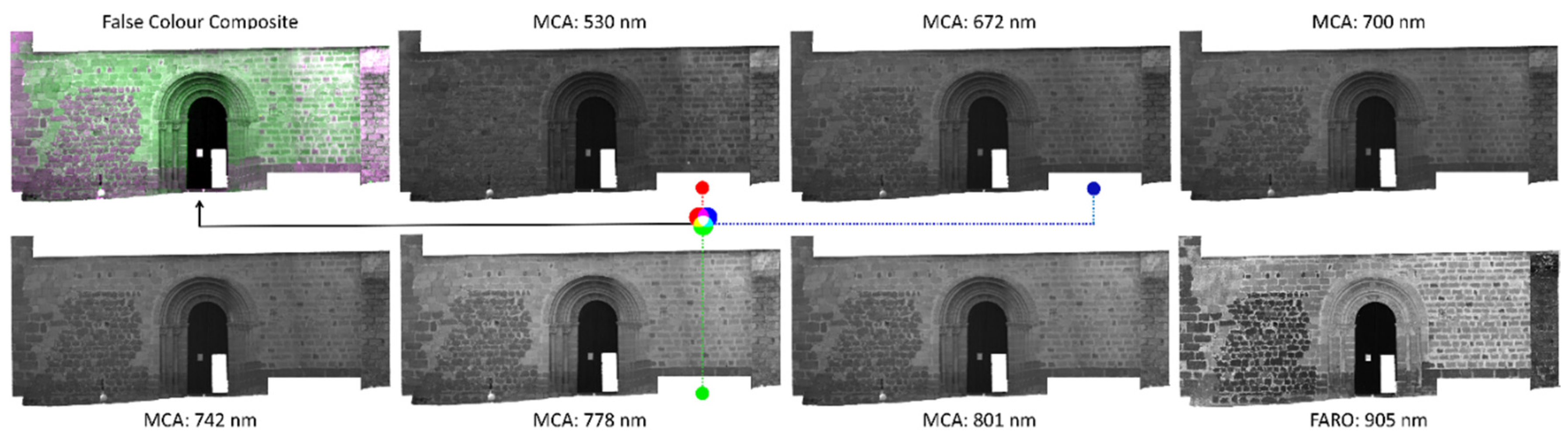
3.1. Reflectance Orthoimages

In order to compare the discrimination capability of both technologies to distinguish building materials and pathologies a first unsupervised classification of the orthoimages belonging to each sensor was performed (Figure 8 and Figure 9). A final supervised classification with the complete set of 7 orthoimages was carried out. For each informational class manually representative areas distributed throughout the façade (between 5 and 10 polygons per class) were selected. This last classification serves as a reference with which to compare each individual unsupervised classification. The steps followed by the workflow are shown in Figure 1.
Figure 8. Mini MCA6 map for the 5-clusters unsupervised classification.
Remotesensing 08 00080 g008
Figure 9. FARO Focus3D map for the 5-clusters unsupervised classification.
Remotesensing 08 00080 g009

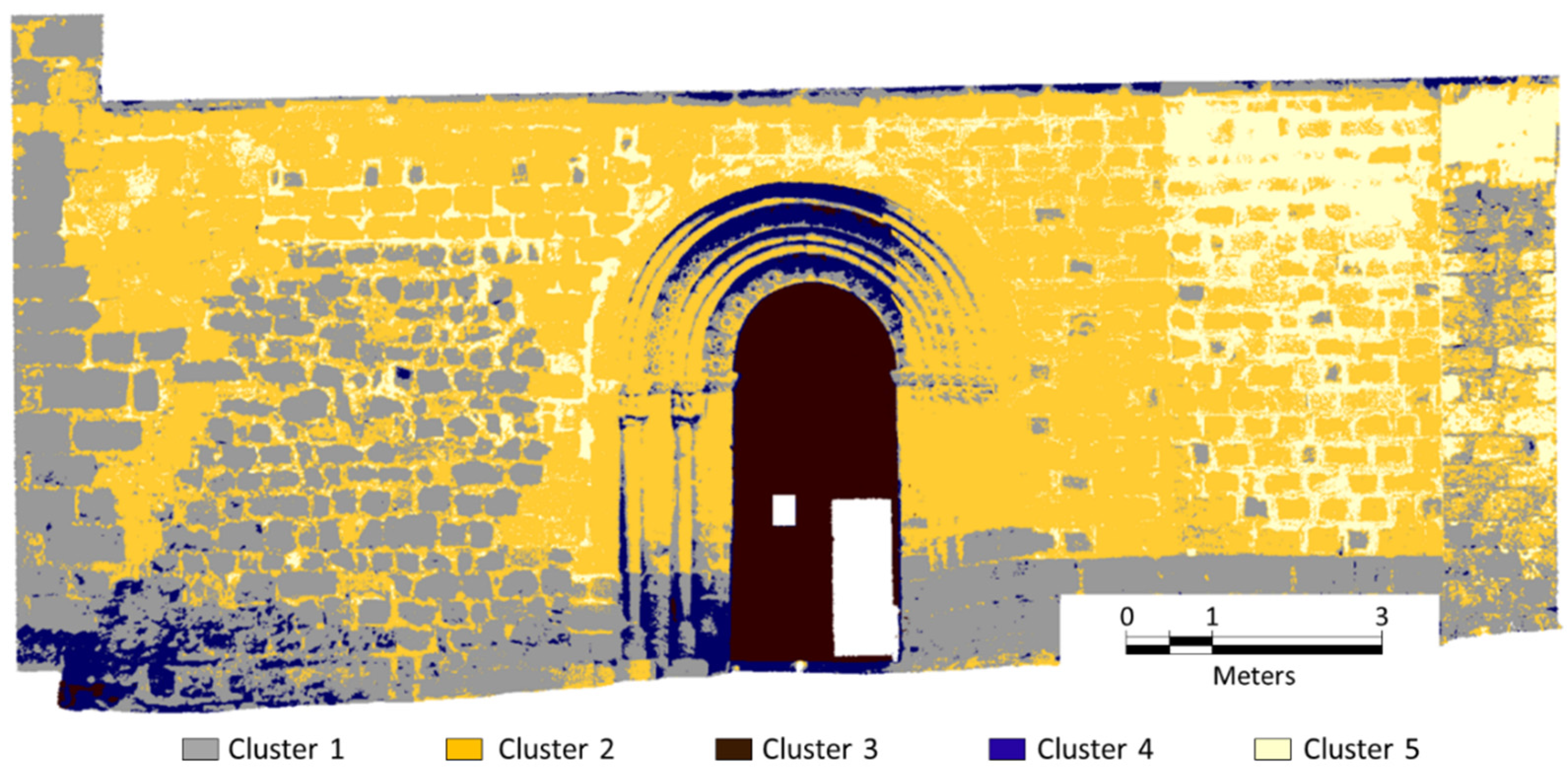
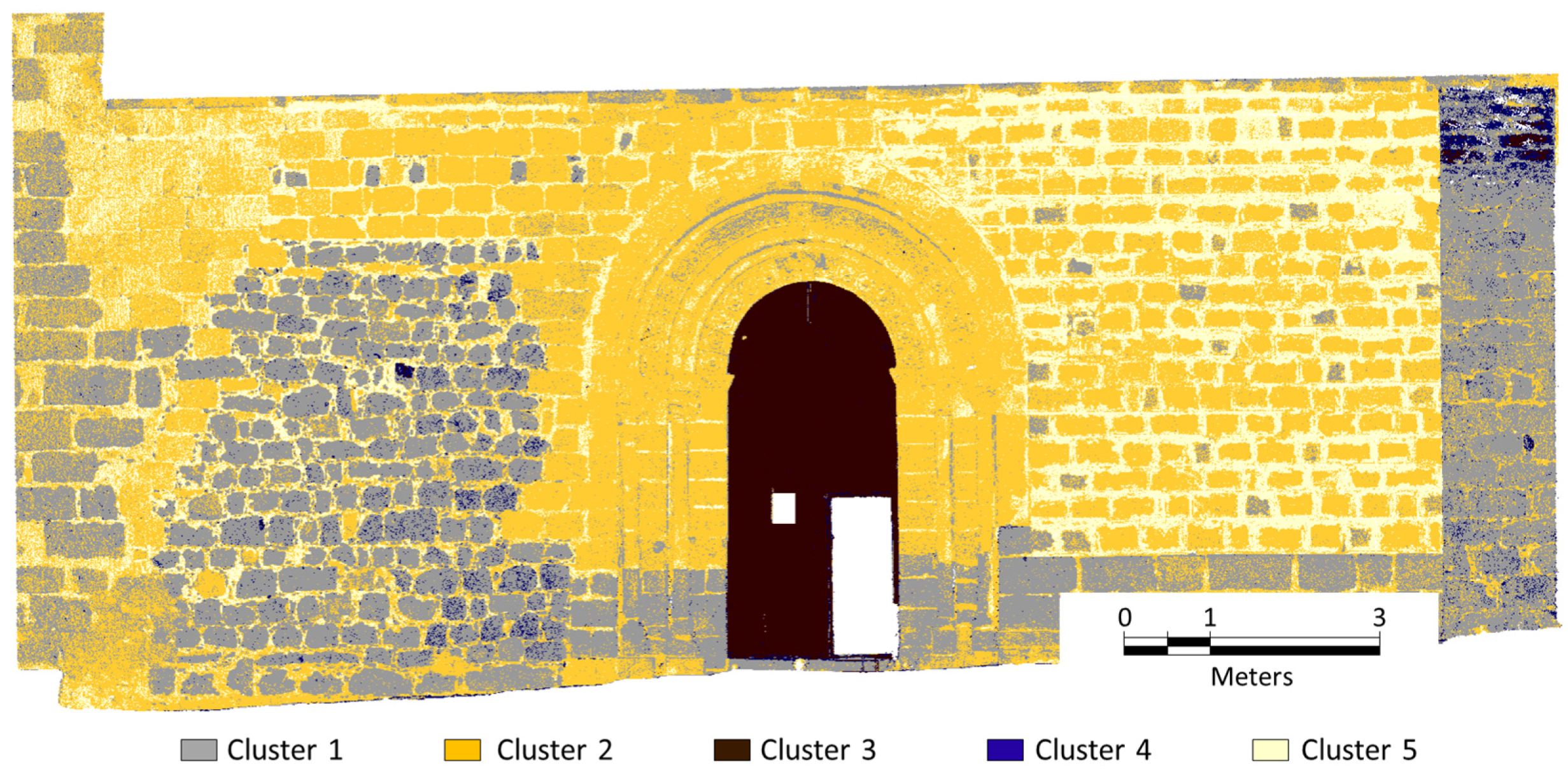
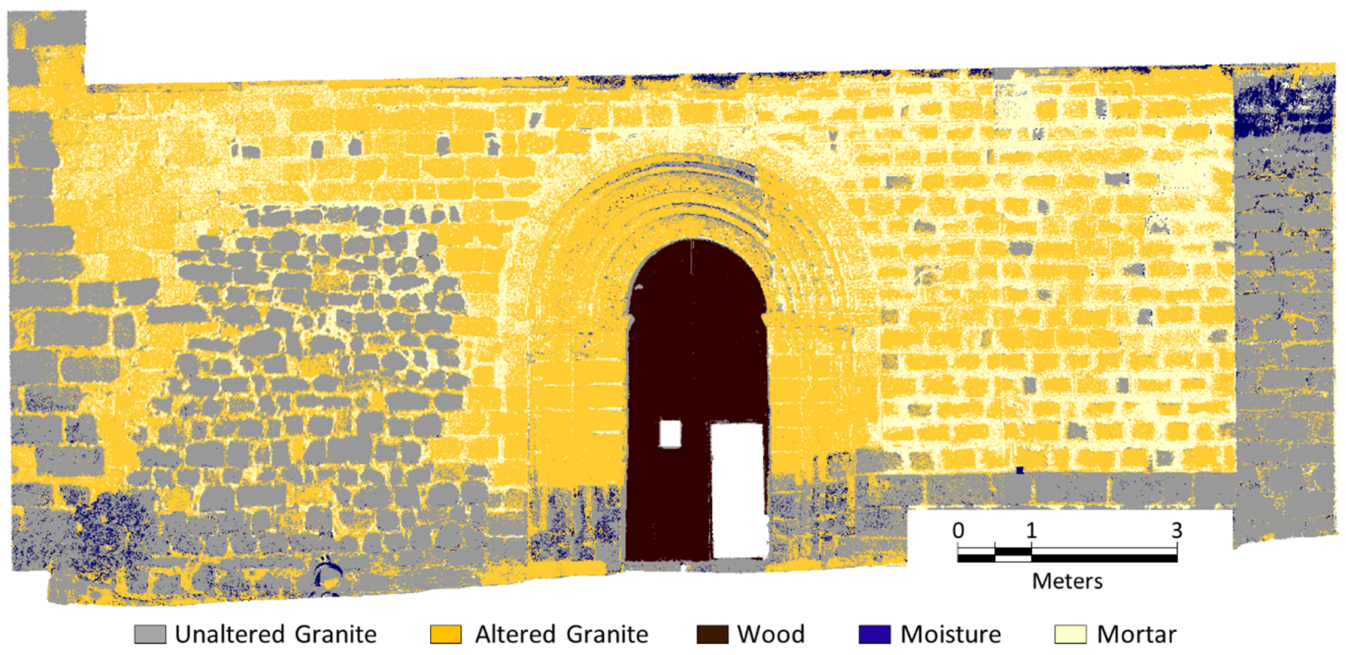
3.2. Orthoimages Classifications

Ten predefined clusters were used in each case for the unsupervised classification algorithm. In all of them, the resulting map showed the existence of affected areas. Post-analysis reduced the number of clusters. The number of clusters decreased from 10 (initial clusters) to 5 thematic classes with real meaning: (1) unaltered granite; (2) altered granite; (3) wood (door of the church); (4) areas with moisture evidences (caused by capillarity or filtration water) and (5) mortar between blocks.
It is noteworthy that results from Mini MCA6 are not fully satisfactory due to large variability in lighting conditions during the data acquisition. As mentioned at the beginning of Section 3, the fieldwork took place on 27 July 2012, with a 6-h total acquisition time. Although radiometric calibration reduces the effects of the lighting variability between different data acquisition time, passive sensors are really sensitive to shady areas. These areas could be seen in Figure 7, specifically in the orthoimages from the Mini MCA6, and also in the classification results of the entrance area in Figure 8 (blue color). However, this is not the case for the active sensor, FARO Focus3D, where the continuity of materials and pathologies is a remarkable aspect.
Comparing the results with a visual inspection, results correspond quite well to reality for both types of existing granites (unaltered and altered) and wood by three well differentiated clusters in all classification maps (Figure 8 and Figure 9). Regarding pathologies detection, it was not possible to draw final conclusions with these first unsupervised classifications. However, this process served to perform a better defined supervised classification.
With the aim of having a reference with which to compare both unsupervised classification maps, a supervised classification of the full set of 7 orthoimages in reflectance values was performed (Figure 10) taking into account the two existing variants of granite, their pathologies derived primarily from moisture and the other informational classes.
The best overall accuracy for the Fuzzy K-means unsupervised classifications was 74.39%, achieved for the FARO Focus3D map in contrast with the 66.04% accuracy for the Mini MCA6 map. This indicates that the best correlation between the number of pixels correctly classified and the total number of pixels occurred for this near infrared active sensor.
Table 2 contrasts the results of the supervised classification (based on training areas) with the unsupervised classification for each sensor. The table shows the sum of pixels belonging to each class for each of the classifications performed. The count is expressed as a percentage of the total number of classified pixels (1,154,932 without taking the background class into account).
Figure 10. Multisensory map for the 5 informational classes supervised classification.
Remotesensing 08 00080 g010
Table 2. Pixels computation belonging to each thematic class.
ClassReference MapMultispectral MapLaser Map
Unaltered granite30.04%28.53%27.33%
Altered granite42.60%48.06%47.27%
Wood5.35%5.67%5.82%
Moisture1.88%4.74%1.31%
Mortar20.13%13.00%18.27%
In a quantitative analysis for the estimation of the two types of granite and wood, results of both sensors are quite similar and really close to the reference map while intensity data from laser scanner are the closest to the reference map results for the estimation of moisture and mortar. Results show higher pixels classified as moisture in the case of multispectral map (2.86% higher with respect to the reference map) and few pixels classified as mortar (7.13% lower than the reference map) due mainly to the altered granite count (whose spectral response has the greatest similarity). Results from the laser sensor are quite similar, greater amount of altered granite by reducing the unaltered granite and mortar detected classes. Note that the best results for moisture detection are achieved with the FARO Focus3D, since humidity has a major interference with this wavelength [40]. Since the pathological classes (moisture and altered granite) are better recognized by the laser scanner and it is the most comprehensive sensor with results closer to the reference, it can be concluded that the active sensor has proven to be the best option to study and detect pathologies and different construction materials for studies with high variability in light conditions where passive sensors are greatly affected.
To evaluate the separability between classes the transformed divergence indicator [41], ranging from 0 to 2, was used as the most widely used quantitative estimator for this purpose [42]. Table 3 shows the separability between the final 5 classes.
Table 3. Transformed divergence for the supervised classification.
Unaltered GraniteAltered GraniteWoodMoisture
Altered granite1.87---
Wood2.002.00--
Moisture1.991.992.00-
Mortar1.981.422.002.00
In general, a high separability was achieved for all 5 classes, highlighting the good separability between the spectral signatures of the two granite types. The worst results were for the mortar and the altered granite classes. This fact is explained by two reasons: on the one hand, the façade sample distance (FSD) of the orthoimages (11 mm in the worst case) was not enough to detect façade areas with smaller thickness of mortar; and on the other, altered granite class presented the closest spectral behavior regarding mortar. With respect to the moisture of the façade, it appeared in lower areas of the shrine (capillarity rising damp) and in the buttress, acting as a filter system for the water from the roof (filtration moisture). These areas are built with unaltered granite blocks since lower areas need to support the loads of the whole building (also in buttress). The radiometric misunderstanding between moisture and unaltered granite did not occur in the case of altered granite since the latter is part of the center of the façade, a low humidity area.

3.3. Accuracy Assessment

In order to assess the accuracy of the unsupervised classifications, the supervised classification approach based on maximum likelihood algorithm served as reference. Five classes and the seven bands available were considered in the classification process. Accuracy results for the case of the Mini MCA6 multispectral camera and the FARO Focus3D laser scanner were 66.04% and 74.39% respectively as mentioned above, and according to the Cohen’s Kappa coefficient [43] the level of agreement was 0.50 and 0.621 respectively (excluding the null class).
Furthermore, as mentioned in Section 2.1, an ASD FieldSpec3 spectroradiometer was used to measure several samples of granite for a parallel study. Those measures, in this study, have been used as reference and as a complement to the above analysis to compare the spectral signatures of these construction materials with the discrete reflectance results obtained from the Mini MCA6 and the FARO Focus3D (Figure 11). The spectral signatures and deviations of the two types of granite present in the façade are plotted for the wavelength range covered by both sensors (530–905 nm).
In Figure 11, the graph continuous lines show at any wavelength the mean value of the reflectances of unaltered and altered granite samples distributed along the façade and measured with the spectroradiometer (a total of 6 and 7 samples of granite, respectively). On the other hand, the colored areas represent the standard deviation of that spectroradiometer measurements. Regarding the discrete values of reflectance achieved with the sensors (discrete points) they result from the mean reflectance value of the “unaltered granite” and “altered granite” classes for each sensor’s wavelength of the supervised classification map. The “mortar” class was not finally evaluated due to its variability in thickness along the façade and due to the fact that the FSD achieved was in many areas greater than its thickness.
It should be mentioned that a great fit of the reflectance values from both sensors (discrete points) was achieved for both granite real spectral behaviors (spectroradiometer measurements) with admissible standard deviations associated (lower than those associated with spectroradiometer measurements). For both evaluated materials, the mean error was 0.007 (in the range 0–1), being the maximum 0.049 (in the range 0–1), which is better than the expected error for this vicarious calibration technique (around 5%).
The confusion matrices for the assessment of both sensors are shown in Table 4 and Table 5, where the main diagonal indicates the percentage of pixels that have been correctly classify and the off-diagonal values represent misclassification. The producer and user accuracies as well as the overall accuravy are given. Regarding the moisture class, a significant performance improvement of the classifier is observed for this class for the operating wavelength of the FARO Focus3D. In the case of the mortar class, the Mini MCA6 do not bring good results mainly due to the errors produced during the 6-band registration process. Finally, we mention that in the case of the unaltered and altered granites, little variations were observed between both sensors.
Figure 11. Spectral signatures of the two different types of granites, (a) unaltered and (b) altered, measured with the ASD spectroradiometer for the wavelength interval covered by the sensors used (Mini MCA6 and FARO Focus3D) where points are obtained from the orthoimages in reflectance values.
Remotesensing 08 00080 g011
Table 4. Confusion matrix of the Mini MCA6 unsupervised classification.
MoistureMortarAltered GraniteUnaltered GraniteWoodUser Accuracy
Moisture40.14%25.40%0.54%33.92%0.01%40.14%
Mortar0.06%39.11%59.53%1.31%0.00%39.11%
Altered granite3.79%7.69%73.86%14.61%0.05%73.86%
Unaltered granite6.56%5.30%16.39%70.75%1.01%70.75%
Wood0.00%0.00%0.00%0.00%100.00%100.00%
Producer accuracy21.10%57.71%66.00%74.28%94.26%
Overall accuracy: 66.04%
Table 5. Confusion matrix of the FARO Focus3D unsupervised classification.
MoistureMortarAltered GraniteUnaltered graniteWoodUser Accuracy
Moisture52.46%1.04%23.17%19.81%3.52%52.46%
Mortar0.00%60.46%37.36%2.18%0.00%60.46%
Altered granite0.05%12.81%78.29%8.64%0.20%78.29%
Unaltered granite0.29%1.49%21.70%75.47%1.04%75.47%
Wood0.48%0.00%0.00%0.00%99.52%99.52%
Producer accuracy89.64%68.32%68.68%83.62%91.81%
Overall accuracy: 74.39%
To conclude, it should be highlight that the improvement in both the overall accuracy and the Kappa coefficient is significant in the case of working with radiometrically calibrated sensors as opposed to the use uncalibrated ones [17]. The results for the Mini MCA6 have experienced a 24% improvement in terms of overall accuracy and 23% regarding the Kappa coefficient. Furthermore, the improvement from the use of the calibrated FARO Focus3D was of 29% and 35% regarding the overall accuracy and Kappa coefficient, respectively. Results worsen in the case of the Mini MCA6 due to two factors; the first is that the camera is a passive sensor, so it is sensitive to changes in light conditions and shadow areas during data acquisition. The second error factor is caused by the slave image registration process, as has been mentioned above, due to the errors in the determination of baselines, angular misalignments and the internal parameters of the camera. Any error in those parameters is propagated into the final multispectral orthoimage, being worsened for higher spatial resolutions, where the geometric pixel footprint in the object may differ depending on the wavelength.

4. Conclusions

The work presented in this paper shows a comparison of the classification results from the use of different radiometrically calibrated sensors to detect pathologies in materials of historical buildings façades. By combining the use of two different data acquisition techniques (active and passive), two sensors were examined: a multispectral camera and a 3D laser scanner. The results show the different radiometric responses of the ashlars of a church with different damages levels (mainly moisture). The classification algorithms used for the classification processes were the Fuzzy K-means and the maximum likelihood classification algorithms.
A complete description of the workflow followed is outlined describing the data acquisition, pre-processing (including sensors radiometric calibrations), orthoimages generation and the application of two classification algorithms to assess the final results. Our results show that the most comprehensive sensor for which the best results were obtained is the FARO Focus3D. This is possibly due to the advantage of working in an active way with no need of external radiation. As a result, classification maps were not affected by different lighting conditions during data acquisition. Furthermore, geometric models of the study object can be derived thanks to its data capture. With these models, physical pathologies (such as fissures, desquamations, etc.) could be analyzed and both these damages and chemical pathologies could be quantified. However, for the challenge of the registration of 6 wavelength bands, the results from the Mini MCA6 were quite good. Considering all those issues and with the experience of working with these sensors in previous studies, it is concluded that the radiometric calibration of the sensors is crucial since it contributes to improving the accuracy of the outcomes (a 35% Kappa coefficient improvement in the case of the FARO Focus3D). Thus, a sensor combination with laser scanning as a primary choice is the best solution for pathology detection and quantification. By adding the intensity information to visible or multispectral information, results of classification improve in a quantitative and a qualitative way.
In future work, the use of a hyperspectral camera or another laser scanner operating in the shortwave infrared as a complement of the sensors proposed will improve the pathologies detection and the overall accuracy results since the spectral resolution of the study would be increased. In addition, and for non-carved historical buildings, the roughness of the façade would be calculated from the scan points in order to have additional data of the materials so it can help in the discrimination process. Finally, and regarding the data acquisition of passive sensors, constant favorable climatic conditions will be planned so that the accuracy of its classification results may be significantly improved.

Acknowledgments

This work has been partially supported by the Spanish Ministry of Economy and Competitiveness through the ENERBIUS project “Integrated system for the energy optimization of buildings” (ENE2013-48015-C3-3-R).

Author Contributions

All authors conceived, designed and performed the experimental campaign. Susana del Pozo and Pablo Rodriguez-Gonzálvez implemented the methodology and analyzed the results. Susana del Pozo wrote the manuscript and all authors read and approved the final version.

Conflicts of Interest

The authors declare no conflict of interest.

References

  1. Marszalek, M. Deterioration of stone in some monuments exposed to air pollution: A Cracow case study. In Air Pollution and Cultural heritage; Taylor and Francis: London, UK, 2004; pp. 151–154. [Google Scholar]
  2. Corvo, F.; Reyes, J.; Valdes, C.; Villaseñor, F.; Cuesta, O.; Aguilar, D.; Quintana, P. Influence of air pollution and humidity on limestone materials degradation in historical buildings located in cities under tropical coastal climates. Water Air Soil Pollut. 2010, 205, 359–375. [Google Scholar] [CrossRef]
  3. Fort, R.; de Azcona, M.L.; Mingarro, F. Assessment of protective treatment based on their chromatic evolution: Limestone and granite in the Royal Palace of Madrid, Spain. In Protection and Conservation of the Cultural Heritage in the Mediterranean Cities; Galan, E., Zezza, F., Eds.; CRC Press/Balkema: Sevilla, Spain, 2002; pp. 437–441. [Google Scholar]
  4. Weritz, F.; Kruschwitz, S.; Maierhofer, C.; Wendrich, A. Assessment of moisture and salt contents in brick masonry with microwave transmission, spectral-induced polarization, and laser-induced breakdown spectroscopy. Int. J. Archit. Herit. 2009, 3, 126–144. [Google Scholar] [CrossRef]
  5. Lambers, K.; Eisenbeiss, H.; Sauerbier, M.; Kupferschmidt, D.; Gaisecker, T.; Sotoodeh, S.; Hanusch, T. Combining photogrammetry and laser scanning for the recording and modelling of the late intermediate period site of pinchango alto, Palpa, Peru. J. Archaeol. Sci. 2007, 34, 1702–1712. [Google Scholar] [CrossRef]
  6. González-Aguilera, D.; Gómez-Lahoz, J.; Sánchez, J. A new approach for structural monitoring of large dams with a three-dimensional laser scanner. Sensors 2008, 8, 5866–5883. [Google Scholar] [CrossRef]
  7. Buckley, S.J.; Howell, J.; Enge, H.; Kurz, T. Terrestrial laser scanning in geology: Data acquisition, processing and accuracy considerations. J. Geol. Soc. 2008, 165, 625–638. [Google Scholar] [CrossRef]
  8. Armesto, J.; Ordóñez, C.; Alejano, L.; Arias, P. Terrestrial laser scanning used to determine the geometry of a granite boulder for stability analysis purposes. Geomorphology 2009, 106, 271–277. [Google Scholar] [CrossRef]
  9. Höfle, B.; Pfeifer, N. Correction of laser scanning intensity data: Data and model-driven approaches. ISPRS J. Photogramm. Remote Sens. 2007, 62, 415–433. [Google Scholar] [CrossRef]
  10. Kaasalainen, S.; Kukko, A.; Lindroos, T.; Litkey, P.; Kaartinen, H.; Hyyppä, J.; Ahokas, E. Brightness measurements and calibration with airborne and terrestrial laser scanners. IEEE Trans. Geosci. Remote Sens. 2008, 46, 528–534. [Google Scholar] [CrossRef]
  11. Franceschi, M.; Teza, G.; Preto, N.; Pesci, A.; Galgaro, A.; Girardi, S. Discrimination between marls and limestones using intensity data from terrestrial laser scanner. ISPRS J. Photogramm. Remote Sens. 2009, 64, 522–528. [Google Scholar] [CrossRef]
  12. Lichti, D.D. Spectral filtering and classification of terrestrial laser scanner point clouds. Photogramm. Record 2005, 20, 218–240. [Google Scholar] [CrossRef]
  13. Mather, P.; Tso, B. Classification Methods for Remotely Sensed Data, 2nd ed.; CRC Press: Boca Raton, FL, USA, 2009. [Google Scholar]
  14. Lerma, J.L. Multiband versus multispectral supervised classification of architectural images. Photogramm. Record 2001, 17, 89–101. [Google Scholar] [CrossRef]
  15. Lerma, J.L. Automatic plotting of architectural facades with multispectral images. J. Surv. Eng. 2005, 131, 73–77. [Google Scholar] [CrossRef]
  16. Ruiz, L.; Lerma, J.; Gimeno, J. Application of computer vision techniques to support in the restoration of historical buildings. ISPRS Int. Arch. Photogramm. Remote Sens. Spatl. Inf. Sci. 2002, 34, 227–230. [Google Scholar]
  17. Hemmleb, M.; Weritz, F.; Schiemenz, A.; Grote, A.; Maierhofer, C. Multi-spectral data acquisition and processing techniques for damage detection on building surfaces. In Proceedings of the ISPRS Commission V Symposium “Image Engineering and Vision Metrology”, Dresden, Germany, 25–27 September 2006.
  18. Del Pozo, S.; Herrero-Pascual, J.; Felipe-García, B.; Hernández-López, D.; Rodríguez-Gonzálvez, P.; González-Aguilera, D. Multi-sensor radiometric study to detect pathologies in historical buildings. ISPRS Int. Arch. Photogramm. Remote Sens. Spat. Inf. Sci. 2015, XL-5/W4, 193–200. [Google Scholar] [CrossRef]
  19. López, D.H.; García, B.F.; Piqueras, J.G.; Alcázar, G.V. An approach to the radiometric aerotriangulation of photogrammetric images. ISPRS J. Photogramm. Remote Sens. 2011, 66, 883–893. [Google Scholar] [CrossRef]
  20. Del Pozo, S.; Rodríguez-Gonzálvez, P.; Hernández-López, D.; Felipe-García, B. Vicarious radiometric calibration of a multispectral camera on board an unmanned aerial system. Remote Sens. 2014, 6, 1918–1937. [Google Scholar] [CrossRef]
  21. Kaasalainen, S.; Ahokas, E.; Hyyppä, J.; Suomalainen, J. Study of surface brightness from backscattered laser intensity: Calibration of laser data. IEEE Geosci. Remote Sens. Lett. 2005, 2, 255–259. [Google Scholar] [CrossRef]
  22. Soudarissanane, S.; Lindenbergh, R.; Menenti, M.; Teunissen, P. Scanning geometry: Influencing factor on the quality of terrestrial laser scanning points. ISPRS J. Photogramm. Remote Sens. 2011, 66, 389–399. [Google Scholar] [CrossRef]
  23. Al-amri, S.S.; Kalyankar, N.V.; Khamitkar, S.D. A comparative study of removal noise from remote sensing image. Int. J. Comput. Sci. Issue 2010, 7, 32–36. [Google Scholar]
  24. Zheng, Y.; Lin, S.; Kambhamettu, C.; Yu, J.; Kang, S.B. Single-image vignetting correction. IEEE Trans. Pattern Anal. Mach. Intell. 2009, 31, 2243–2256. [Google Scholar] [CrossRef] [PubMed]
  25. Reshetyuk, Y. Self-Calibration and Direct Georeferencing in Terrestrial Laser Scanning. Doctoral Thesis in Infrastructure, Geodesy; Royal Institute of Technology (KTH): Stockholm, Suecia, 2009. [Google Scholar]
  26. Honkavaara, E.; Arbiol, R.; Markelin, L.; Martinez, L.; Cramer, M.; Bovet, S.; Chandelier, L.; Ilves, R.; Klonus, S.; Marshal, P. Digital airborne photogrammetry—A new tool for quantitative remote sensing? A state-of-the-art review on radiometric aspects of digital photogrammetric images. Remote Sens. 2009, 1, 577–605. [Google Scholar] [CrossRef] [Green Version]
  27. Biggar, S.; Slater, P.; Gellman, D. Uncertainties in the in-flight calibration of sensors with reference to measured ground sites in the 0.4–1.1 μm range. Remote Sens. Environ. 1994, 48, 245–252. [Google Scholar] [CrossRef]
  28. Dinguirard, M.; Slater, P.N. Calibration of space-multispectral imaging sensors: A review. Remote Sens. Environ. 1999, 68, 194–205. [Google Scholar] [CrossRef]
  29. Kaasalainen, S.; Krooks, A.; Kukko, A.; Kaartinen, H. Radiometric calibration of terrestrial laser scanners with external reference targets. Remote Sens. 2009, 1, 144–158. [Google Scholar] [CrossRef]
  30. Jelalian, A.V. Laser Radar Systems; Artech House: New York, NY, USA, 1992. [Google Scholar]
  31. Bourke, P. An algorithm for interpolating irregularly-spaced data with applications in terrain modelling. In Proceedingsof the Pan Pacific Computer Conference, Beijing, China, 1 January 1989.
  32. Attene, M. A lightweight approach to repairing digitized polygon meshes. Vis. Comput. 2010, 26, 1393–1406. [Google Scholar] [CrossRef]
  33. Kraus, K. Photogrammetry: Geometry from Images and Laser Scans, 2nd ed.; Walter de Gruyter: Berlin, Germany, 2007. [Google Scholar]
  34. Albertz, J.; Kreiling, W. Photogrammetrisches Taschenbuch; Herbert Wichmann Verlag: Berlin, Germany, 1989. [Google Scholar]
  35. Bezdek, J.C. Pattern Recognition with Fuzzy Objective Function Algorithms; Plenum Press: New York, NY, USA, 1981. [Google Scholar]
  36. Kannan, S.; Sathya, A.; Ramathilagam, S.; Pandiyarajan, R. New robust fuzzy C-Means based gaussian function in classifying brain tissue regions. In Contemporary Computing; Ranka, S., Aluru, S., Buyya, R., Chung, Y.-C., Dua, C., Grama, A., Gupta, S.K.S., Kumar, R., Phoha, V.V., Eds.; Springer: Berlin, Germany, 2009; pp. 158–169. [Google Scholar]
  37. Richards, J.A. Remote Sensing Digital Image Analysis; Springer: Berlin, Germany, 1999; Volume 3. [Google Scholar]
  38. Lillesand, T.; Kiefer, R.W.; Chipman, J. Remote Sensing and Image Interpretation, 7th ed.; John Wiley & Sons: Hoboken, NJ, USA, 2015. [Google Scholar]
  39. García, F.A.F. La Invención de la Iglesia de san Segundo. Cofrades y Frailes Abulenses en los Siglos xvi y xvii; Institución Gran Duque de Alba: Ávila, Spain, 2006. [Google Scholar]
  40. Rantanen, J.; Antikainen, O.; Mannermaa, J.-P.; Yliruusi, J. Use of the near-infrared reflectance method for measurement of moisture content during granulation. Pharm. Dev. Technol. 2000, 5, 209–217. [Google Scholar] [CrossRef] [PubMed]
  41. Davis, S.M.; Landgrebe, D.A.; Phillips, T.L.; Swain, P.H.; Hoffer, R.M.; Lindenlaub, J.C.; Silva, L.F. Remote Sensing: The Quantitative Approach; McGraw-Hill International Book Co.: New York, NY, USA, 1978. [Google Scholar]
  42. Tolpekin, V.; Stein, A. Quantification of the effects of land-cover-class spectral separability on the accuracy of markov-random-field-based superresolution mapping. IEEE Trans. Geosci. Remote Sens. 2009, 47, 3283–3297. [Google Scholar] [CrossRef]
  43. Cohen, J. Weighted kappa: Nominal scale agreement provision for scaled disagreement or partial credit. Psychol. Bull. 1968, 70, 213–220. [Google Scholar] [CrossRef] [PubMed]

