Article

Frescoed Vaults: Accuracy Controlled Simplified Methodology for Planar Development of Three-Dimensional Textured Models

by
Marco Giorgio Bevilacqua
1,†,
Gabriella Caroti
2,†,
Isabel Martínez-Espejo Zaragoza
2,† and
Andrea Piemonte
2,*,†
1
Energy, Systems, Territory and Construction Engineering Department (DESTeC), University of Pisa, Largo Lucio Lazzarino 1, 56122 Pisa, Italy
2
Civil and Industrial Engineering Department (DICI), University of Pisa, Largo Lucio Lazzarino 1, 56122 Pisa, Italy
*
Author to whom correspondence should be addressed.
These authors contributed equally to this work.
Submission received: 30 November 2015 / Revised: 1 March 2016 / Accepted: 7 March 2016 / Published: 14 March 2016

Abstract

:
In the field of documentation and preservation of cultural heritage, there is keen interest in 3D metric viewing and rendering of architecture for both formal appearance and color. On the other hand, operative steps of restoration interventions still require full-scale, 2D metric surface representations. The transition from 3D to 2D representation, with the related geometric transformations, has not yet been fully formalized for planar development of frescoed vaults. Methodologies proposed so far on this subject provide transitioning from point cloud models to ideal mathematical surfaces and projecting textures using software tools. The methodology used for geometry and texture development in the present work does not require any dedicated software. The different processing steps can be individually checked for any error introduced, which can be then quantified. A direct accuracy check of the planar development of the frescoed surface has been carried out by qualified restorers, yielding a result of 3 mm. The proposed methodology, although requiring further studies to improve automation of the different processing steps, allowed extracting 2D drafts fully usable by operators restoring the vault frescoes.

Graphical Abstract

1. Introduction

Planar development of more or less complex curved surfaces, also possibly decorated, is of great interest for experts working in the field of documentation and preservation of cultural heritage. The scientific community has addressed the problem in a rigorous way, with both analytical [1] and digital [2,3,4,5,6] methodologies. These investigations have led to the development of software applications that have only partially automated the procedures required for planar development of curved surfaces. Studies carried out by the authors have not found as yet any commercial tool allowing automated and controlled development of geometry and texture.
The goal of this research was to study a simplified methodology enabling both planar development of geometry and texture of frescoed vaults (surveyed with geomatics techniques) and checking of the errors related to the different operating steps. In particular, this methodology has been developed in the case of the “a schifo” vault typology [7,8] and does not provide any kind of cartographic projection. It uses very common commercial software and includes some processing steps requiring user operation.

2. State of the Art

3D photorealistic environments allow engineers, historians and restorers to research, investigate, and simulate outcomes of restoration projects before these are executed. For all these aspects, 3D-textured metric modeling is currently the most sought after tool for cognitive evaluation and operating approach in the field of cultural heritage [9]. Creation of a 3D-textured model includes three steps: geometry modeling, parameterization and texture creation.

2.1. Geometry Survey

Laser scanning is a well-established surveying methodology, whose output is readily usable for representing historical and architectural heritage [10,11,12,13,14,15,16,17]. Accuracy and resolution attainable in comparatively short times (last-generation scanners for architectural surveys can acquire millions of points per second with sub-centimeter accuracy) are the main strengths of these systems although prices are still quite high.
The new approach to softcopy photogrammetry realized by Structure from Motion (SfM) and MVS (Multi-View Stereo) algorithms generates very dense 3D color point clouds quite similar in size to those produced from laser scanning surveys [18,19,20,21,22,23]. However, even if software evolution in this field is very fast and performance is good in terms of processing time, and the amount of manageable data and obtainable precisions are gradually improving, these procedures may not always be considered reliable. In fact, matching algorithms can be very sensitive to recording and illumination differences and not reliable in poorly textured or homogeneous regions. This can result in noisy point clouds and/or difficulties in feature extraction [24]. These matching algorithms could suffer from variable precision, strongly dependent on the pattern present on surveyed objects, as well as the difficulty of having control of the achievable accuracy at the geometric and morphological levels [20,25].

2.2. Texture Mapping

In large-scale 3-D models used as supporting documentation in restoration works, textures are not a mere aesthetic complement. In fact, besides supporting construction, material and chromatic studies, they also act as metric surveying tools, providing, once applied to the models, a guideline for measurements. Therefore, if textures have to meet these requirements, their positioning accuracy must be consistent with the scale used, besides having the necessary chromatic precision [26].
Many laser scanners have built-in cameras, whose relative orientation is calibrated by the manufacturer, which allow direct true coloring of point clouds. These textures are characterized by a high geometric accuracy, but the systems used for the photographic takes usually do not achieve good results in terms of resolution and color fidelity [27].
Simplified, realistic-looking models may not suffice for restorers, who require rigorous texture mapping for both morphology and color information. In these cases, it is essential to resort to a dedicated photographic campaign, performed with high quality cameras as regards optics, sensor size and image post-processing.
In the case of SfM software, the creation of models and textures is almost contextual, and the procedure usually involves self-calibration of the camera, which also takes account of characteristic distortion parameters. In these models, although textures usually have good photographic quality, it is necessary to check the overall morphological reliability.

2.3. Vault Development

Commercial and open-source software currently available are capable to render architectures in 3D as regards formal appearance and color. On the other hand, operative steps of restoration interventions still require large-scale, 2D metric surface representations. The transition from 3D to 2D representation, with the related geometric transformations, has not yet been fully formalized and still features open issues, e.g., in the case of planar development of frescoed vaults [28]. Methodologies proposed so far on this subject provide transitioning from point cloud models to known mathematical surfaces (developed on plane, or not), and afterwards seeking an ideal representation of the actual surface, losing some architectural and building details in this process [29,30,31,32,33]. To the best knowledge of the authors, modeling and reverse engineering software commonly used do not have dedicated tools that enable automatic development of geometry and textures. Moreover, the tools that only partially solve the problem do not take account of the introduced deformations.

3. Materials and Methods
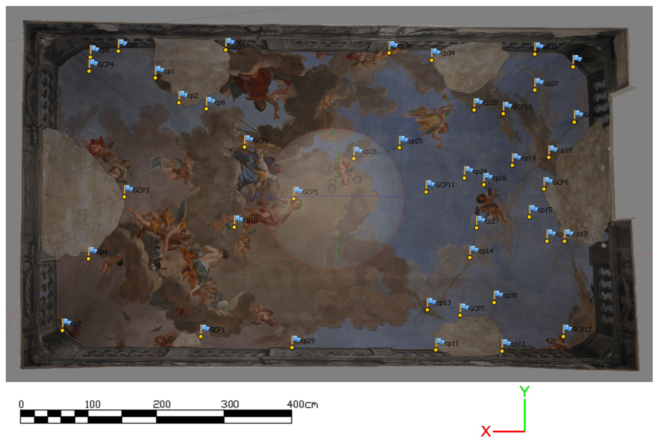
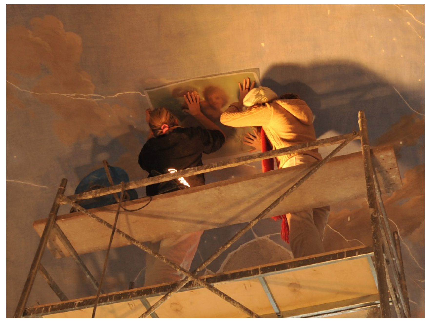
In order to achieve planar development of frescoed vaults, textured 3D models of the vaults are required. These should feature good geometric accuracy to identify the ideal geometric root that best fits the actual vault. Textures associated with the models will have good radiometric quality and true colors, and will also faithfully reproduce position and dimension of any fresco detail.

3.1. The Case Study

The object of this investigation is a vault in Palazzo Roncioni (Pisa, Italy). Its entire surface is covered by a XVIII century fresco, painted by Tuscan painter G.B. Tempesti, which has over time undergone extensive damage (cracks, plaster gaps, etc.). Currently, the vault is the subject of safety and restoration work. A laser scanning survey of the vault has been performed with the pulse shift-based laser scanner Leica Geosystems C10 ScanStation, with a point cloud density of about 70 pts/cm2 on average. Use of a phase-based laser scanner would have allowed for more accurate results at short distances and therefore less noisy reference data. The photogrammetric survey was performed with a Nikon D700 SLR camera (f = 20 mm lens) at about 4.5 m range, ensuring a roughly 2-mm pixel covering on the vault surface. It has been subjected to image processing via SfM algorithms, granting an overlap ≥70%.

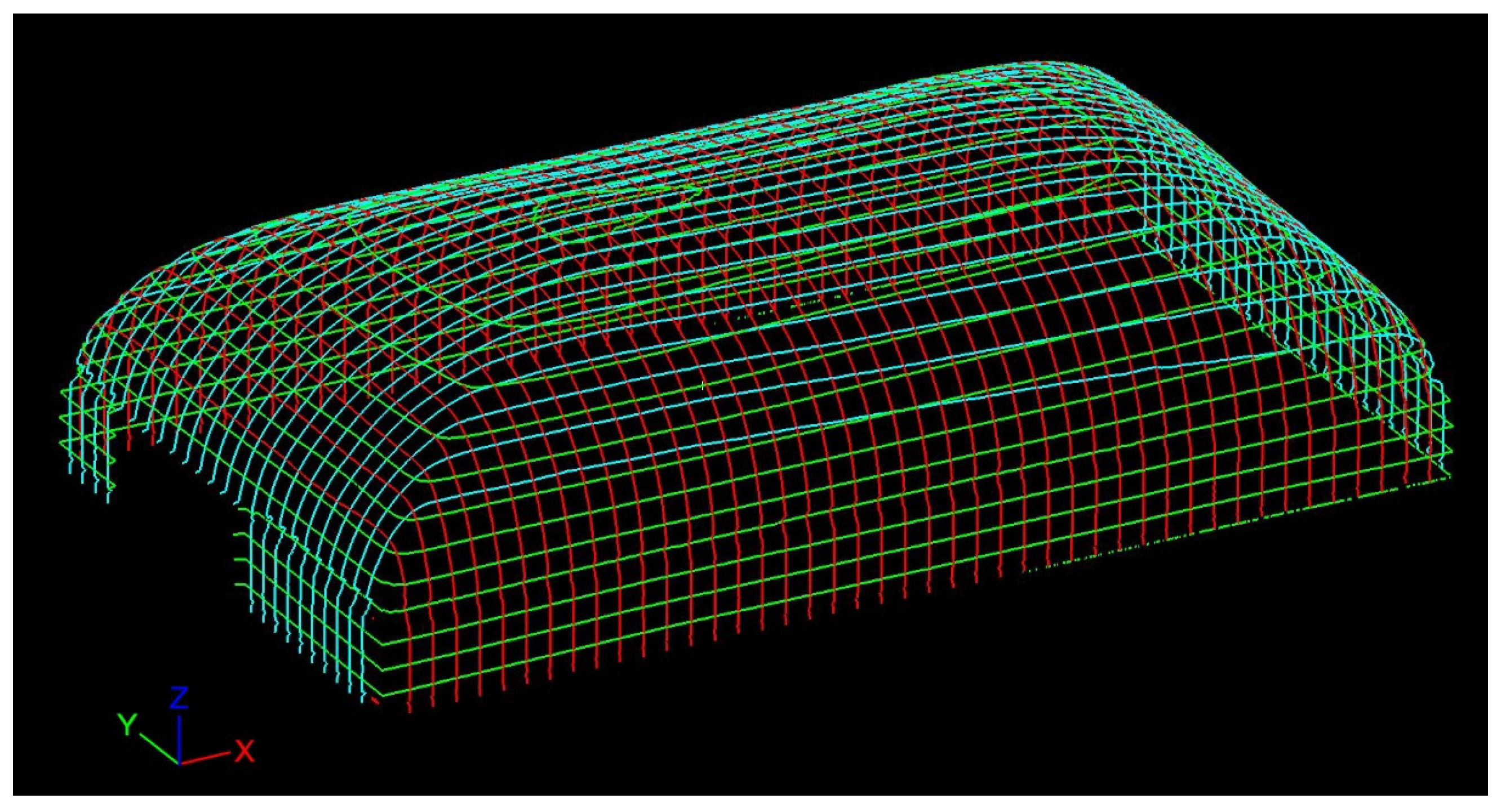
3.2. 3D Modeling and Texturing

A separate 3D TIN model has been built by means of each surveying methodology. Both models have been rigorously registered in the same reference system due to the extrapolation, from the colored point cloud, of the coordinates of 12 Ground Control Points (GCPs). These have been chosen as easily identifiable fresco details, spread evenly across the entire vault, and have been used in the processes of scaling and rototranslation of the photogrammetric model.
The model obtained via laser scanning survey, henceforth referred to as “model LASER” (Figure 1c), features homogenous geometric precision and a high enough resolution to show elements in the sub-centimeter range (cracks, plaster displacements, etc.). As regards textures, images collected via the on-board camera (single image 17° × 17°, 1920 × 1920 pixel) do not grant adequate radiometric quality. The model obtained by means of SfM/MVS methodology, henceforth referred to as “model SfM/MVS”, features uneven geometric precision, mostly in the areas where radiometric uniformity reduces the performance of the SfM algorithms (Figure 1b). On the other hand, it has been obtained by a photographic campaign executed with a high quality camera, so that despite some local errors in detail rendering, image orientation is substantially fit to the needs of the application, as detailed later. A new textured model (“model SfM/LASER”) has been generated via SfM software from the geometry of model LASER and the images orientated for creation of model SfM/MVS (Figure 1a).
Model SfM/LASER is the best result for geometry and texture quality, starting from collected data. As regards processing time, this texturing process definitely has lower requirements than single image orientation based on GCPs [26].

3.3. Vault Development

Point clouds, either collected by laser scanning (Cloud LASER) or obtained by photogrammetry (Cloud SfM/MVS), have been framed in a single reference system. The X- and Y-axes lie in the speculated vault impost plan, which is not horizontal (axes origin in a corner, X-axis on the long side and Y-axis on the short side) and the Z-axis completes the orthogonal triplet. In order to proceed with the 2D vault development, the 3D model has been analyzed.

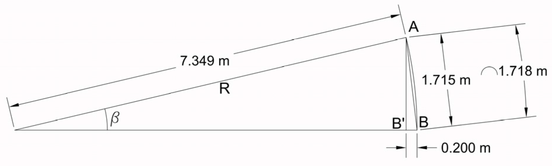
3.3.1. Analysis and Preliminary Processing of Laser Data

In order to define the geometric components that constitute the vault, a dense contour (step = 2 cm) representation of model LASER has been generated according the three coordinate planes (Figure 2).
The study of this contour representation (Figure 3) has allowed identification of nine discontinuity directions that divide the vault in 6 areas, each featuring its own section profiles with almost constant radius: areas 2, 4 and 6, close to the vault impost, have greater section profile radii than those in the upper part of the vault (areas 1, 3 and 5). Separation between the lower and upper parts of the vault is located at about one third of the vault height above the impost plane.
The interpretation of these results suggested that the vault could be generated from the combination of several elements belonging to different cylindrical surfaces, and could be part of the “a schifo” type. This includes a lower portion, similar to a section of a pavilion vault, and an upper one, named “specchio” (mirror), which features so wide a curvature to appear almost planar. This vault type has been widely used in architecture since Renaissance exactly in the case of fresco decorations.
Once the hypotheses about the building type of the vault have been substantiated, the values of the geometric parameters (axis and radius) of the elementary cylindrical surfaces that best fit the point clouds of each of the six areas detected were computed by means of approximation algorithms.
As an example, approximation by cylindrical surfaces of the long side (Figure 4) yielded the following results (Table 1).
Analysis of Standard Deviation (STDV) should take in account that the vault does not actually show neat transitions between contiguous cylindrical surfaces, but rather the curvature radius changes gradually. In fact, the higher values of the difference between ideal and actual surfaces are found in these transition areas (Figure 5).

3.3.2. Analysis of the Development Methodology

In order to achieve a planar development of vault geometry and texture using well known and easily available software tools, a methodology using model representation by contours, rather than by ideal shapes such as cylinders, has been investigated and applied to this case study.
For this purpose, just the contour lines lying in the XY coordinate plane have been used in a CAD environment, with a 20-cm step (Figure 6).
It has been assumed that vault sections between adjacent contours were planar. Contours have been assumed as connections between adjacent planes. In order to appraise the error introduced by this assumption, an orthogonal section of the interpolating cylinders has been checked. In the most unfavorable situation (Figure 7), the difference between the section arc Equation (1) and the related chord Equation (2), bounded by two adjacent contours, has been computed.
AB ^ = β · R
AB ¯ = 2 · R · sin ( β / 2 )
On an arc length = 1.718 m, the maximum difference was 3 mm, with a sub-millimeter relative error. This approximation has been deemed acceptable. For the planar development of the XY contour lines model with a 20-cm step (the same used to detect the different portions of the vault), the crown of the vault has been outlined in CAD at 1:1 scale (line AB in Figure 8).
Subsequent contour lines have been separately developed by trilateration for each surface of the vault. Assuming the extremes of the previous contour as fixed points, the extremes of the next contour have been plotted. Figure 8 shows how planar geometric development of the actual vault lacks the regular course found in the development of an ideal surface constituted just by portions of cylinder with parallel axes.
Sections defined by ZX (blue lines) and ZY (red lines) planes have then been superimposed on the development of the XY sections (green lines).
Besides geometric vault development, sections are also required as a reference for correct texture placement on the developed model.
In order to apply textures to the developed geometric model, the following methodology has been chosen.
For each surface, eight directions have been identified to set orthogonal views of 3D model SfM/LASER. These directions are orthogonal to the axis of the theoretical cylinders and, starting from the horizontal view, tilted by 15° relative to the previous view.
For each viewing direction, images of the model of vault portion bounded by a 15° cylindrical arc have been collected. These are an orthogonal projection of the vault texture on an orthogonal plane relative to the viewing direction [34]. Fresco elements projected in this way are obviously deformed.
Accepting the simplification that the vault is represented by the surfaces of the interpolating cylinders, it is possible to quantify this deformation. As for the orthogonal projection on a plane tangent to the cylinder, there is no deformation along parallel directions relative to the tangency line, while deformation is highest along orthogonal directions. Linear deformation module (ml) at the extremes of the orthogonally projected area is defined by Equation (3).
m l = AB ¯ AB ^ = 2 · R · s i n ( β / 2 ) R · β
In the projection used, deformation is highest in the furthest point relative to the tangency line (for breadth = 15°, distance is about 1 m), where ml = 0.9970 and deformation = 3 mm (Figure 9).
In accordance with the operators dealing with the restoration of the fresco, this deformation has been deemed acceptable.
Each orthogonal view of model SfM/LASER has been performed in two configurations and saved in two separate image files. Configuration 1 provided for superimposing the section lines to the model (Figure 10a). Configuration 2 viewed the model with just the high quality texture applied (Figure 10b).
The following processing steps have therefore been run for each image pair:
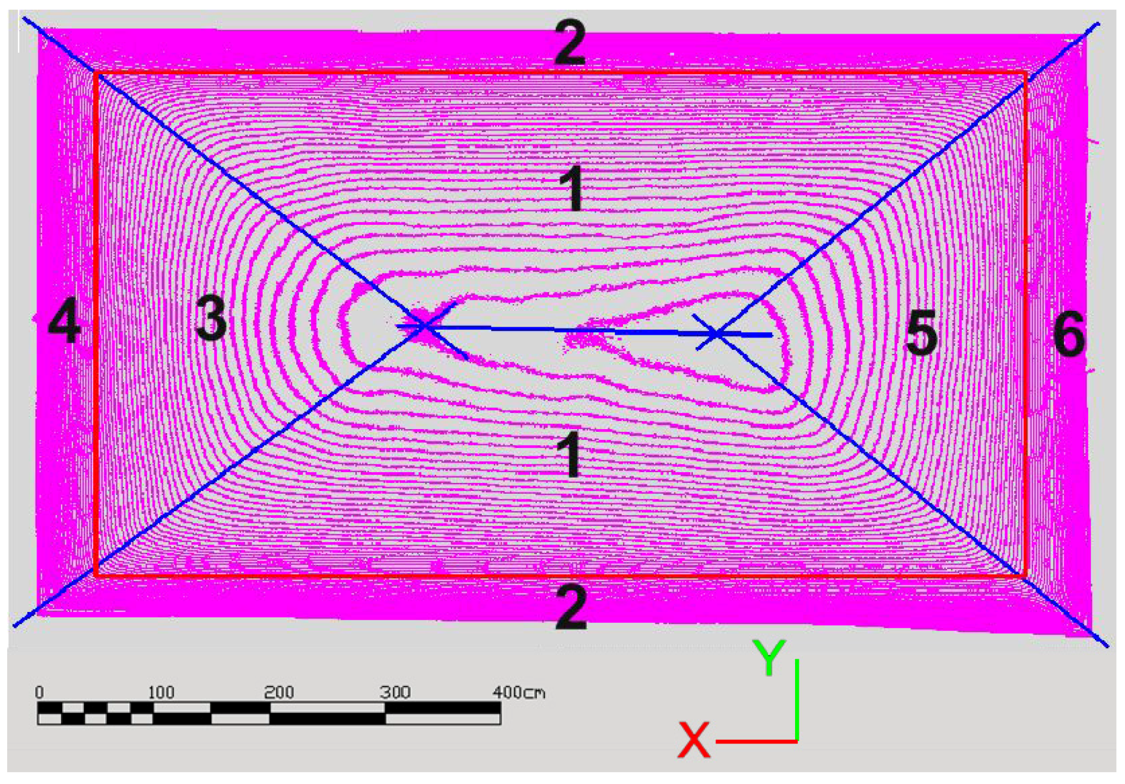
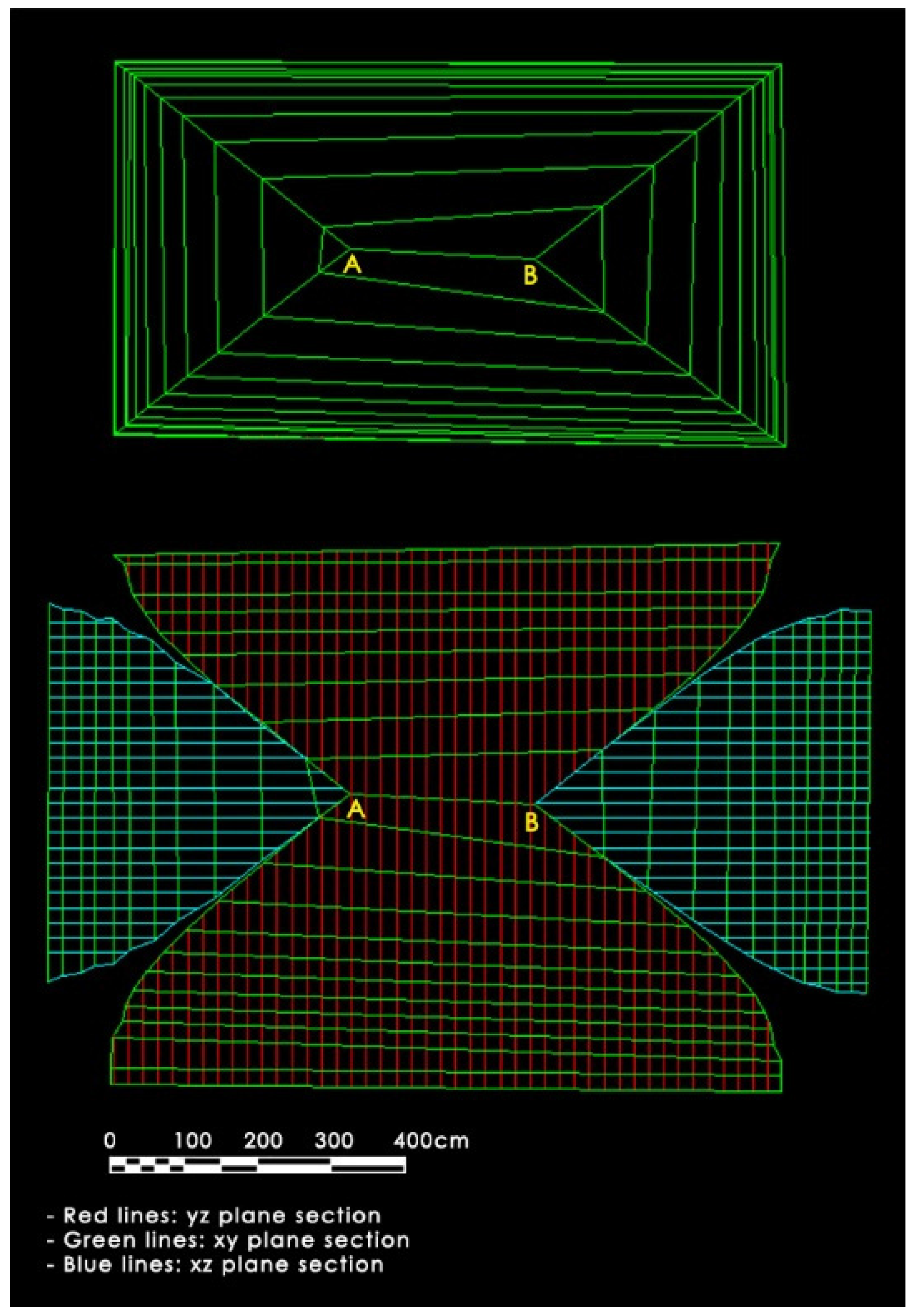
  • Image pairs and the geometric vault development frame (Figure 8) have been imported in the same photo editing software environment.
  • A single block has been created with both images, so that any transformation applied to any one image was similarly applied to the other.
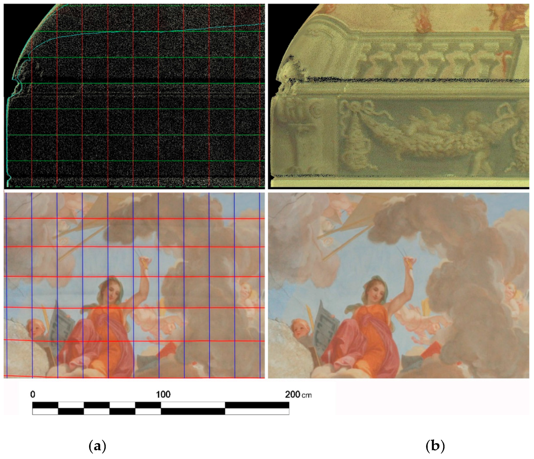
  • The layer containing the image with just the texture has been turned off, leaving visible just the image with the section lines.
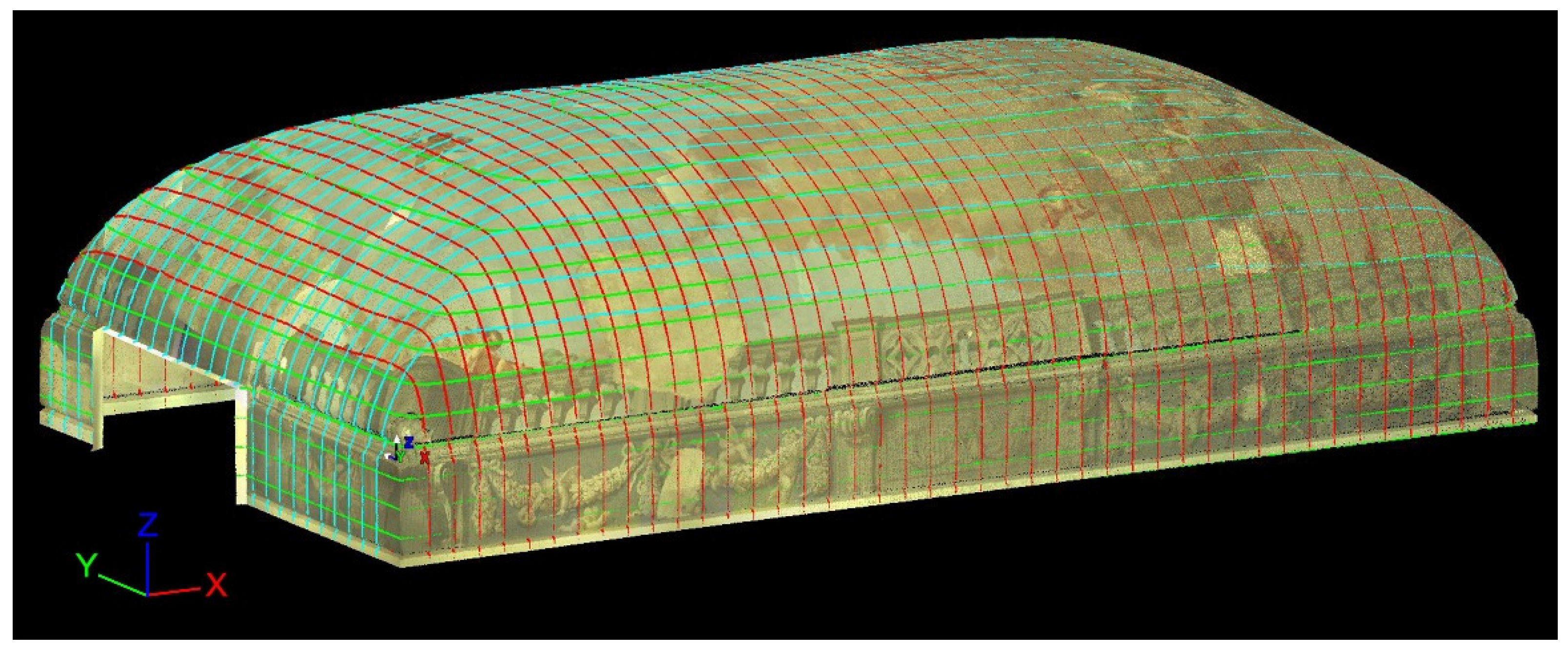
  • The image has been scaled and moved on the geometric frame, assuming the section lines obtained with XZ and YZ planes (vertical lines in Figure 10) as reference.
As proof of the small deformation of the images, it has been noticed that after scaling the image in the direction of the axis of the interpolating cylinders for a single projection direction, it aligns with images derived from other projection directions at less than the computed deformation (Figure 11).

4. Results and Discussion

In order to validate the methodology used, results must be checked for both geometric precision of the different models obtained and precision of placement, dimension and shape of the applied textures. Finally, the quality of the planar development of the vault was assessed (Figure 12).

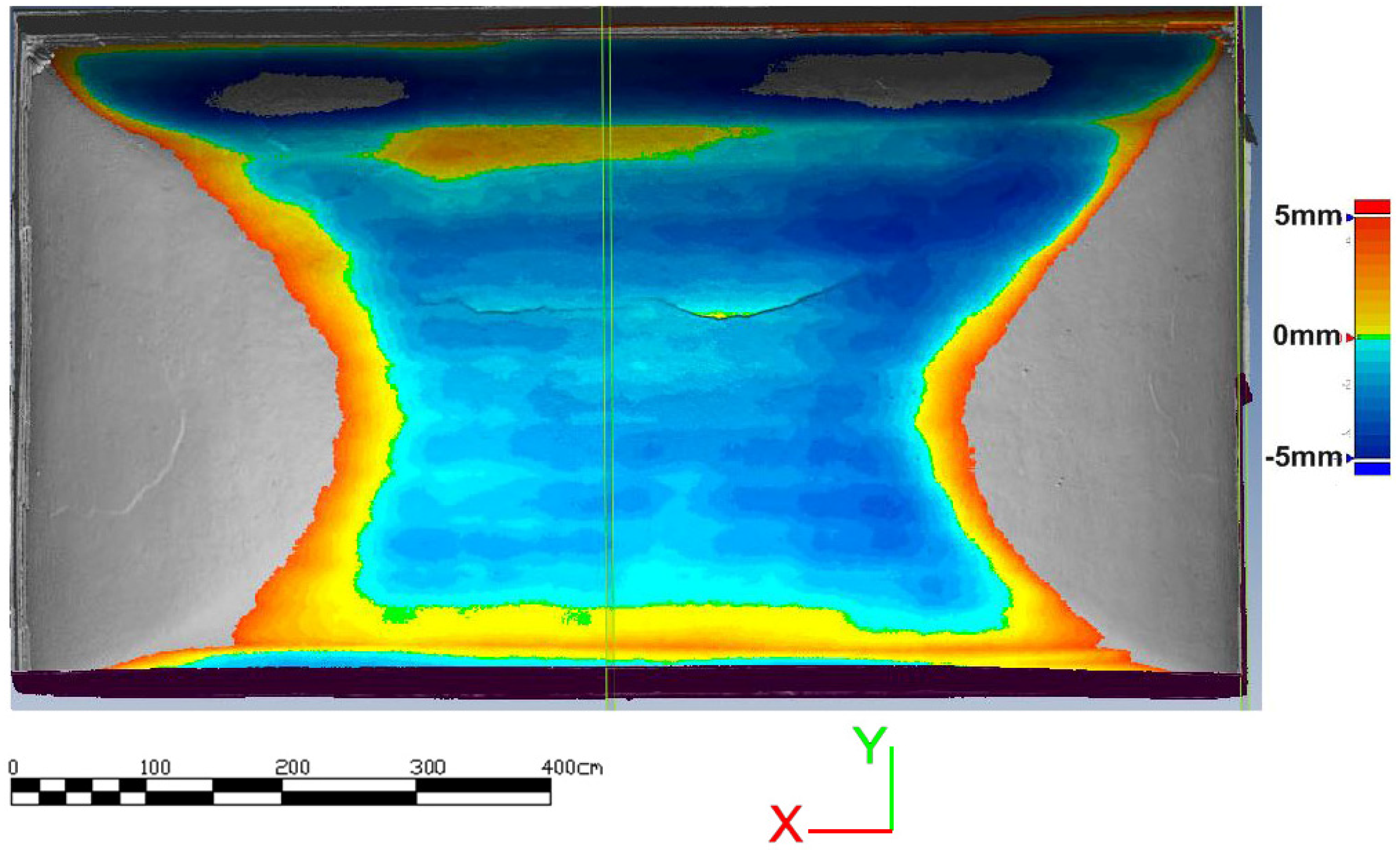
4.1. Assessment of Model Geometrical Accuracy

The laser scanning colored point cloud model (Cloud LASER) can be assumed as the absolute geometric reference in this application. It has very high point density, and allows extraction of coordinates of features for both geometry (cracks, gaps, etc.) and painting (boundary lines, color transitions, etc.) with a sub-centimeter resolution.
Standard deviation obtained by comparing Cloud LASER with Model LASER is 1 mm, with peaks in the 3 mm range. These results highlight that the transition from point cloud to surface model entails a small decay of geometric precision.
A second check has been performed comparing Cloud LASER with Cloud SfM/MVS; the standard deviation averaged at 3 mm, with peaks of about 6 mm.
Finally, Cloud LASER has been compared against Model SfM/MVS; the standard deviation was 3 mm on average, peaking at about 10 mm.
These results show that image orientation in SfM is substantially accurate and confirm the mean reprojection error involved with orientating each image via SfM to be 0.70 pixel with an average of 9000 tie points per image. On the other hand, maximum deviation values are in the range of 7–10 mm and refer to cracks and plaster collapse borders. Figure 13, Figure 14, Figure 15, Figure 16 and Figure 17 show an overview of the fresco and some details on local deviations.
Taking into account all these cases, greater deviations are found when surveyed surfaces are orthogonal to the vault. SfM/MVS methodology does not correctly represent the transitions typical of deep cracks and delamination. This result is in the authors’ opinion due to the fact that these surface regions are acquired by inclined views with different inclinations and sometimes with the camera axis parallel to the surface. This fact, reported in the literature, leads to worse performance of the matching algorithms [24].
Hence, the overall accuracy of the SfM-derived model is good (3 mm), but shows some flaws precisely in the regions of most interest to restorers. This processing methodology, on the other hand, has the advantage of significantly lower resource requirements: manual intervention is limited to inputting the support points to orient and scale the model.
These considerations on geometric precision led to the choice of Model SfM/LASER as a starting model for vault development.

4.2. Texture Dimension and Positioning Accuracy Assessment

After geometric accuracy of the models has been checked, texturing precision has also been monitored. For this purpose, the coordinates of 36 Control Points (CPs) have been extracted by Cloud LASER. These coordinates have been firstly compared with those obtained by digitizing the points on the images and obtaining their 3D position in Cloud SfM/MVS (Figure 18). The comparison provided the statistics displayed in Table 2.
Subsequently, the same points have been digitized directly on Model SfM/LASER. A comparison with the reference CP coordinates yielded the results displayed in Table 3.
This comparison shows that precision checks on texture yielded a slightly worse result relative to those on geometry. Such an outcome was predictable, assuming the addition of errors for geometry with those for image orientation and texture projection, as well as those for direct CP collimation on Model SfM/LASER.

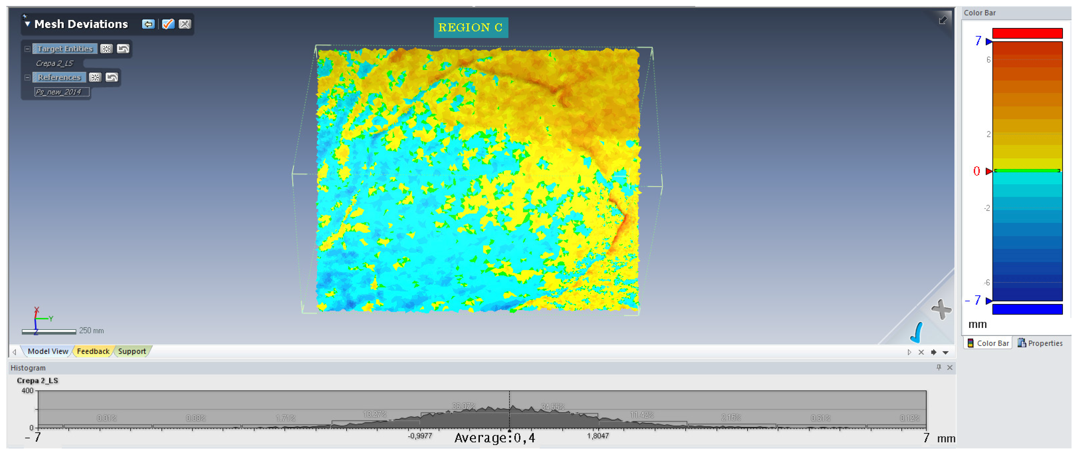
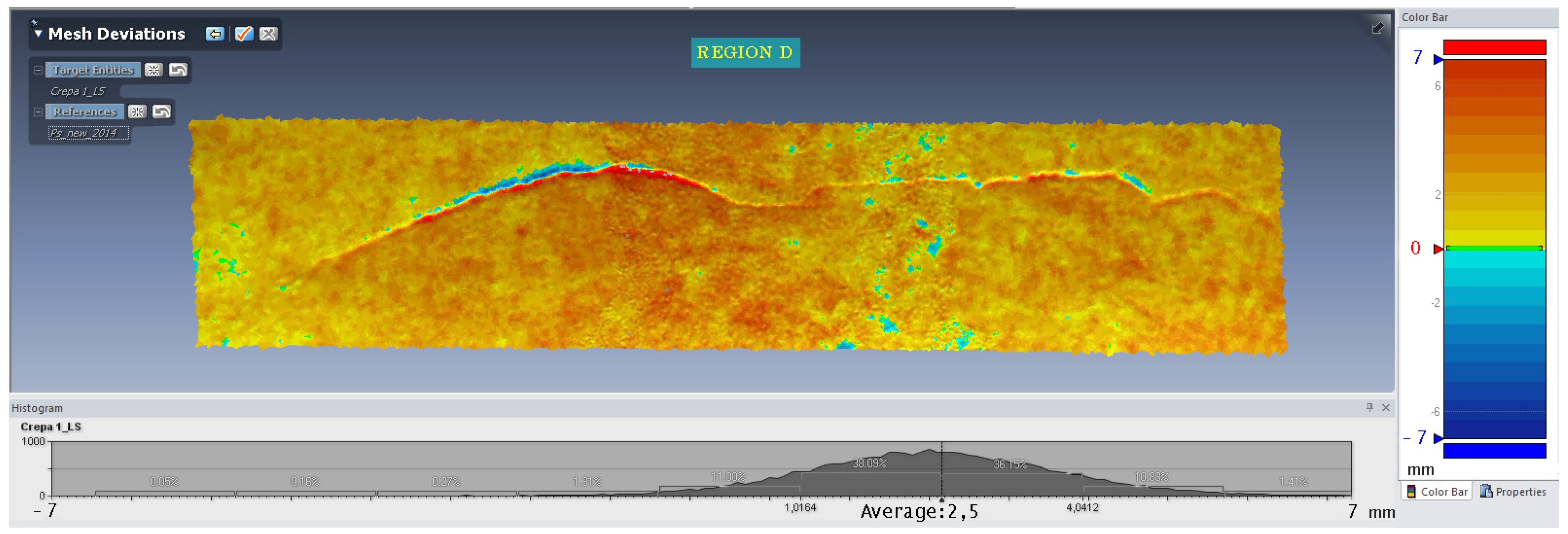
4.3. Vault Development Accuracy Assessment

Besides the 3D comparison between Model SfM/LASER and Cloud LASER, planar development has also been validated at actual scale. Some portions of the image, representing the vault development, have been printed at 1:1 scale on A0 tracing paper. Subsequently, restorers checked the prints directly with the represented fresco portions (Figure 19), noticing the accordance of shapes and dimension of the checked portions in line with the deformations already expected and accepted in the processing steps. On the same tracing paper sheet, restorers have drafted the outlines of the actual fresco paintings; the resulting accuracy is 3 mm.

5. Conclusions

The methodology discussed has proposed a simplified solution for the problem of a metrically correct planar representation of a frescoed “a schifo” vault. The processing steps shown can be carried out even by relatively inexperienced users and do not require specific software.
A peculiar feature of this methodology is the creation of collages of several orthogonal views of the textured 3-D model, thanks to geometrical references provided by the section lines of the model. These lines are visible in the three-dimensional model, its geometric development and on the images used for the collage.
The methodology proposed for modeling, texturing and planar development was verified by both calculating the theoretical error introduced by the single processing step and by comparing the final products with a reference survey and then directly with the surveyed object.
The theoretical development accuracy is 3 mm. The comparison between the laser scanner model textured with oriented images through SFM and the original laser scanning point cloud yielded a 3-mm accuracy. Finally, the direct verification of the development of the model confirmed an accuracy of 3 mm, which allowed drafts to be obtained that are fully usable by restorers for 3D fresco reconstruction on a vaulted surface.
In particular, these are most useful for faithful reconstruction of the geometry in damaged fresco portions, for which a photographic documentation suitable for 3-D modeling is available.
The same methodology can also be applied to domes and vaults of different types. The authors are currently planning further testing on barrel and pavilion vaults and on elliptical and spherical domes.
The present research will be prosecuted with the aim of automating the different processing steps, particularly as regards monitoring of deformations and errors introduced in the final representation.
Further interest also lies in investigating differences between developments obtained by extracting contours by actual surfaces or by approximating them to ideal surfaces.

Acknowledgments

This research work was funded by the University of Pisa internal research funds and by PRIN (Programmi di Ricerca Scientifica di Rilevante Interesse Nazionale—Scientific Research Programs of Relevant National Interest) 2010–2011 funds (coordinator: Raffaele Santamaria—Pisa local research unit).

Author Contributions

This research was performed by Marco Giorgio Bevilacqua, Gabriella Caroti, Isabel Martínez-Espejo Zaragoza and Andrea Piemonte. Each author contributed extensively and equally to prepare this paper.

Conflicts of Interest

The authors declare no conflict of interest.

References

  1. Dequal, S. An unconventional application of analytical plotters to architectural photogrammetry: Projection, plotting and digitizing on non plane surfaces. Int. Arch. Photogramm. Remote Sens. Spat. Inf. Sci. 1988, 27, 140–146. [Google Scholar]
  2. Karras, G.E.; Petsa, E.; Dimarogona, A.; Kouroupis, S. Photo-textured rendering of developable surfaces in architectural photogrammetry. In Virtual and Augmented Architecture (VAA’01); Springer: London, UK, 2001; pp. 147–158. [Google Scholar]
  3. Karras, G.E.; Patias, P.; Petsa, E. Digital monoplotting and photo-unwrapping of developable surfaces in architectural photogrammetry. Int. Arch. Photogramm. Remote Sens. 1996, 31, 290–294. [Google Scholar]
  4. Georgopoulos, A.; Makris, G.N.; Tournas, E.; Ioannidis, C.H. Digitally developing works of art. In Proceedings of the CIPA 2001 International Symposium, Potsdam, Germany, 18–21 September 2001.
  5. Valanis, A. Fitting, portrayal and mapping for the production of 2nd order surfaces photomosaics. Int. Arch. Photogramm. Remote Sens. 2002, 34, 463–467. [Google Scholar]
  6. Lerma, J.L.; Tortosa, R.V. Digital development of a small Valencian tower. Int. Arch. Photogramm. Remote Sens. Spat. Inf. Sci. 2004, 35, 451–454. [Google Scholar]
  7. Pera, L. Tecnica Dell’architettura. Tipologia Strutturale; Goliardica: Pisa, Italy, 1987. [Google Scholar]
  8. De la Plaza Escudero, L. Diccionario Visual de Términos Arquitectónicos; Grandes Temas Cátedra: Madrid, Spain, 2008. [Google Scholar]
  9. Lerma, J.L.; Pérez, C. 3D Photorealistic and interactive reconstruction of covered up frescoes. In Recording, Modeling and Visualization of Cultural Heritage; Baltasavias, E., Gruen, A., Van Gool, L., Pateraki, M., Eds.; Taylor & Francis Group: London, UK, 2006; pp. 485–491. [Google Scholar]
  10. Bevilacqua, M.G.; Caroti, G.; Piemonte, A. Rilievi integrati della Basilica romanica di San Gavino a Porto Torres. In Proceedings of the 16a Conferenza Nazionale ASITA, Vicenza, Italy, 6–9 November 2012; pp. 391–396.
  11. Caroti, G.; Piemonte, A. An integrated survey for knowledge and preservation of a cultural heritage: The Albanian fortified citadel of Elbasan. Int. Arch. Photogramm. Remote Sens. Spat. Inf. Sci. 2008, 37, 373–378. [Google Scholar]
  12. Caroti, G.; Piemonte, A. Studio relativo al rilevamento di dettaglio di una porzione del transetto nord della chiesa di San Paolo a Ripa d’Arno al fine di procedere al consolidamento strutturale. In Proceedings of the Un incontro informale per i 70 anni del Prof. Carlo Monti, Milano, Italy, 3 May 2012; pp. 1–6.
  13. Dore, C.; Murphy, M. Integration of Historic Building Information Modelling (HBIM) and 3D GIS for recording and managing cultural heritage sites. In Proceedings of the IEEE 18th International Conference on Virtual Systems and Multimedia (VSMM), Milan, Italia, 2–5 September 2012; pp. 369–376.
  14. Juan Vidal, F.; Martínez-Espejo Zaragoza, I. Hypotesisforthe virtual anastilosis of themainchapel of the Iglesia de Los Desamparados de Les Coves de Vinromá. In Proceedings of the 16th International Conference on Cultural Heritage and New Technologies, Vienna, Austria, 14–16 November 2011; pp. 201–212.
  15. Lerma, J.L.; Cabrelles, M.; Navarro, S.; Seguí, A.E. La documentación patrimonial mediante sensores de imagen o de barrido láser. In Documentación Gráfica del Patrimonio; Ministerio de Cultura: Madrid, Spain, 2011; pp. 108–117. [Google Scholar]
  16. Marambio, A.; Pucci, B.; Nuñez, M.A.; Buill, F. La aplicación del escáner láser terrestre en la catalogación del patrimonio arquitectónico del casco histórico de Castellfollit de la Roca. In Proceedings of the VIII Semana Geomática Internacional, Barcelona, Spain, 3–5 March 2009; pp. 1–8.
  17. Martínez-Espejo Zaragoza, I.; Juan Vidal, F. Gestión gráfica avanzada de edificaciones antiguas. In Proceedings of the XI Congreso Internacional de Expresión Gráfica Aplicada a la Edificación, Universidad Politécnica de Valencia, Valencia, Spain, 29 November–1 December 2012; pp. 710–714.
  18. Alsadik, B.; Remondino, F.; Menna, F.; Gerke, M.; Vosselman, G. Robust extraction of image correspondences exploiting the image scene geometry and approximate camera orientation. Int. Arch. Photogramm. Remote Sens. Spat. Inf. Sci. 2013, 40, 1–7. [Google Scholar] [CrossRef]
  19. Guidi, G.; Russo, M.; Beraldin, J.A. Acquisizione 3D e Modellazione Poligonale; McGraw-Hill: Milano, Italy, 2010. [Google Scholar]
  20. Guidi, G.; Remondino, F. 3D Modelling from real data. In Modelling and Simulation in Engineering; Catalin Alexandru, C., Ed.; InTech: Vienna, Austria, 2012; pp. 69–102. [Google Scholar]
  21. Koska, B.; Křemen, T. The combination of laser scanning and structure from motion technology for creation of accurate exterior and interior orthophotos of St. Nicholas Baroque church. Int. Arch. Photogramm. Remote Sens. Spat. Inf. Sci. 2013, 40, 133–138. [Google Scholar] [CrossRef]
  22. Lerma, J.L.; Navarro, S.; Cabrelles, M.; Villaverde, V. Terrestrial laser scanning and close range photogrammetry for 3D archaeological documentation: The upper Palaeolithic Cave of Parpalló as a case study. J. Archaeol. Sci. 2010, 37, 499–507. [Google Scholar] [CrossRef]
  23. Wenzel, K.; Rothermel, M.; Fritsch, D.; Haala, N. Image acquisition and model selection for multi-view stereo. Int. Arch. Photogramm. Remote Sens. Spat. Inf. Sci. 2013, 40, 251–258. [Google Scholar] [CrossRef]
  24. Remondino, F.; Spera, M.G.; Nocerino, E.; Menna, F.; Nex, F. State of the art in high density image matching. Photogramm. Rec. 2014, 29, 144–166. [Google Scholar] [CrossRef]
  25. Apollonio, F.I.; Ballabeni, A.; Gaiani, M.; Remondino, F. Evaluation of feature-based methods for automated network orientation. Int. Arch. Photogramm. Remote Sens. Spat. Inf. Sci. 2014, 40, 47–54. [Google Scholar] [CrossRef]
  26. Caroti, G.; Martínez-Espejo Zaragoza, I.; Piemonte, A. Accuracy assessment in structure from motion 3D reconstruction from UAV-born images: The influence of the data processing methods. Int. Arch. Photogramm. Remote Sens. Spat. Inf. Sci. 2015, 40, 103–109. [Google Scholar] [CrossRef]
  27. Apollonio, F.I.; Remondino, F. Modellazione 3D da sensori attivi Pipeline con laser scanner. In Modelli Digitali 3D in Archeologia: Il Caso di Pompei; Scuola Normale Superiore Pisa: Pisa, Italy, 2010; pp. 94–117. [Google Scholar]
  28. Carpiceci, M. Survey problems and representation of architectural painted surfaces. Int. Arch. Photogramm. Remote Sens. Spat. Inf. Sci. 2011, 38, 523–528. [Google Scholar] [CrossRef]
  29. Menna, F.; Rizzi, A.; Nocerino, E.; Remondino, F.; Gruen, A. High resolution 3D modeling of the behaim globe. Int. Arch. Photogramm. Remote Sens. Spat. Inf. Sci. 2012, 39, 115–120. [Google Scholar] [CrossRef]
  30. Cipriani, L.; Fantini, F.; Bertacchi, S. Survey and representation of vaults and cupolas: An overview on some relevant Italian UNESCO Sites. In Proceedings of the IEEE International Conference on Virtual Systems & Multimedia (VSMM), Hong Kong, China, 9–12 December 2014; pp. 50–57.
  31. Chiabrando, F.; Rinaudo, F. Recovering a collapsed medieval fresco by using 3D modeling techniques. ISPRS Ann. Photogramm. Remote Sens. Spat. Inf. Sci. 2014, 2, 105–112. [Google Scholar]
  32. Pancani, G. Lo svolgimento in vera grandezza delle volte affrescate delle sale dei quartieri al piano terreno di Palazzo Pitti a Firenze. In Proceedings of the Giornate di Studio Il Disegno delle trasformazioni, Napoli, Italy, 1–2 December 2011; pp. 1–11.
  33. Cannella, M. Sviluppo e Rappresentazione Digitale di Superfici Architettoniche Complesse per la Documentazione e il Restauro. Available online: http://hdl.handle.net/10447/130394 (accessed on 25 November 2015).
  34. Meyer, E.; Parisel, C.; Grussenmeyer, P.; Revez, J.; Tidafi, T. A computerized solution for the epigraphic survey in Egyptian Temples. J. Archaeol. Sci. 2006, 33, 1605–1616. [Google Scholar] [CrossRef]
Figure 1. (a) Model SfM/LASER; (b) Model SfM/MVS; (c) Model LASER.
Remotesensing 08 00239 g001
Figure 2. Dense contour model (isometric view).
Remotesensing 08 00239 g002
Figure 3. Discontinuity directions and vault areas (bottom view).
Remotesensing 08 00239 g003
Figure 4. Approximation by cylindrical surface.
Remotesensing 08 00239 g004
Figure 5. Actual 3D model—Cylindrical surface error.
Remotesensing 08 00239 g005
Figure 6. 20-cm step contour lines model.
Remotesensing 08 00239 g006
Figure 7. Section arc—chord comparison.
Remotesensing 08 00239 g007
Figure 8. Geometric development of contours model.
Remotesensing 08 00239 g008
Figure 9. Projection deformation.
Remotesensing 08 00239 g009
Figure 10. (a) Orthogonal view with section lines; (b) Orthogonal view with high quality texture.
Remotesensing 08 00239 g010
Figure 11. Superimposition of orthogonal view on sections model development.
Remotesensing 08 00239 g011
Figure 12. High quality textured model development.
Remotesensing 08 00239 g012
Figure 13. Regions checked for deviations between cloud LASER and model SfM/MVS.
Remotesensing 08 00239 g013
Figure 14. Region A: total plaster collapse borders.
Remotesensing 08 00239 g014
Figure 15. Region B: total plaster collapse borders.
Remotesensing 08 00239 g015
Figure 16. Region C: gap in the fresco.
Remotesensing 08 00239 g016
Figure 17. Region D: crack in the topmost region of the vault.
Remotesensing 08 00239 g017
Figure 18. CPs on the vault.
Remotesensing 08 00239 g018
Figure 19. Development accuracy assessment at 1:1 scale.
Remotesensing 08 00239 g019
Table 1. Approximation by cylindrical surface—radius.
Area 1Area 2
Radius (m)7.3495.280
STDV (m)0.0070.008
Table 2. CP coordinates comparison Cloud LASER—Cloud SfM/MVS.
XYZ
mean (m)0.0000.0000.000
max (m)0.0050.0050.010
STDV (m)0.0020.0030.004
Note: The values are in line with the geometric comparison between point clouds LASER and SfM/MVS.
Table 3. CP coordinates comparison Cloud LASER—Model SfM/LASER.
XYZ
mean (m)0.0000.0000.000
max (m)0.0190.0230.026
STDV (m)0.0070.0070.008

