Article

A Flexible, Generic Photogrammetric Approach to Zoom Lens Calibration

1
School of Civil Engineering and Geosciences, Newcastle University, Newcastle upon Tyne NE1 7RU, UK
2
School of Marine Sciences, Guangxi University, 100 Daxue East Road, Nanning 530004, China
3
School of Remote Sensing and Information Engineering, Wuhan University, 129 Luoyu Road, Wuhan 430079, China
*
Author to whom correspondence should be addressed.
Submission received: 19 January 2017 / Revised: 28 February 2017 / Accepted: 2 March 2017 / Published: 6 March 2017
(This article belongs to the Special Issue Fusion of LiDAR Point Clouds and Optical Images)

Abstract

:
Compared with prime lenses, zoom lenses have inherent advantages in terms of operational flexibility. Zoom lens camera systems have therefore been extensively adopted in computer vision where precise measurement is not the primary objective. However, the variation of intrinsic camera parameters with respect to zoom lens settings poses a series of calibration challenges that have inhibited widespread use in close-range photogrammetry. A flexible zoom lens calibration methodology is therefore proposed in this study, developed with the aim of simplifying the calibration process and promoting practical photogrammetric application. A zoom-dependent camera model that incorporates empirical zoom-related intrinsic parameters into the collinearity condition equations is developed. Coefficients of intrinsic parameters are solved in a single adjustment based on this zoom lens camera model. To validate the approach, experiments on both optical- and digital-zoom lens cameras were conducted using a planar board with evenly distributed circular targets. Zoom lens calibration was performed with images taken at four different zoom settings spread throughout the zoom range of a lens. Photogrammetric accuracies achieved through both mono-focal and multi-focal triangulations were evaluated after calibration. The relative accuracies for mono-focal triangulations ranged from 1: 6300 to 1: 18,400 for the two cameras studied, whereas the multi-focal triangulation accuracies ranged from 1: 11,300 to 1: 16,200. In order to demonstrate the applicability of the approach, calibrated zoom lens imagery was used to render a laser-scanned point cloud of a building façade. Considered alongside experimental results, the successful application demonstrates the feasibility of the proposed calibration method, thereby facilitating the adoption of zoom lens cameras in close range photogrammetry for a wide range of scientific and practical applications.

Graphical Abstract

1. Introduction

1.1. Background

With the ongoing development and extended application of close-range photogrammetry, the demand for increasing flexibility in practical techniques is constantly increasing. For example, in the case of three-dimensional (3D) reconstruction of cultural heritage sites, photogrammetric approaches have primarily been based on the use of prime lens cameras. However, the field of view (FOV) of a camera fitted with a prime lens is unchangeable and can be only varied by adjusting the photographer’s location, which can often be restricted by the local environment. Zoom lenses, however, offer significant levels of versatility in comparison with their prime lens counterparts. Apart from changing focus and aperture settings, a zoom lens camera is also capable of adjusting zoom settings to suit different FOV and depths of field (DOF). Thus, zoom lenses have generally been favored in consumer photography and extensively employed for various low accuracy applications in the field of computer vision, e.g., active stereo vision [1], augmented reality [2], and object detection and tracking [3].
To exploit the advantages of zoom lens cameras in the field of photogrammetry, camera calibration is the primary issue to overcome. Intrinsic parameters, including the principal distance, principal point offsets, and lens distortion parameters are determined during the process of camera calibration [4,5]. In the discipline of photogrammetry, the principal distance and principal point offsets are known as interior orientation (IO) elements describing the metric characteristics of a camera [6]. Due to the deformations created by lenses and their assembly, distortion parameters usually consisting of radial and decentering coefficients are used to compensate the deviations from the rectilinear projection [7]. The position and attitude of a camera in the object coordinate system is represented by exterior orientation (EO) elements, which are known as extrinsic parameters in the field of computer vision [6]. Camera calibration and orientation procedures enable the derivation of accurate 3D metric information in object space from images [8], thus camera calibration is an indispensable procedure for 3D photogrammetric measurements.
Calibration methods directed towards prime lens cameras have been extensively studied over the last few decades [8,9,10,11]. Generally speaking, the traditional emphasis has been on the rigorous geometric camera model in photogrammetry, and on automation and rapid calibration procedures in computer vision [9]. Among these methods, the self-calibrating bundle adjustment [4,12,13] is widely considered to achieve superior accuracy [8] and has been extensively adopted by the photogrammetry community. However, the intrinsic parameters of a zoom lens camera change dramatically with zooming and focusing operations [14,15,16] and the camera model for a prime lens therefore cannot simply be transferred and applied directly to a zoom lens. Under such a scenario this study proposes an enhanced method, developed further to research previously reported in Zheng et al. [16], which aims to develop a suitable zoom lens camera model for photogrammetry. The new approach presented herein is more generally applicable than that of Zheng et al. [16] and the achieved accuracy using EXIF is significantly higher than the relative accuracy of less than 1:1000 that was previously reported. This manuscript explains the new developments and analyzes the reasons for the improved performance over Zheng et al. [16]. Moreover, a successful application of the approach is presented whereby the calibrated zoom lens camera is used to render a point cloud of a building façade, thereby demonstrating the feasibility and applicability of the proposed method.

1.2. Related Work

Chen et al. [17] observe that more attention is required to calibration for precise geometric measurement tasks in image metrology and for unconventional imaging devices. Efforts have previously been made in the calibration of various digital-zoom lens devices, such as computer controllable lens systems [18,19], single-lens reflex cameras [16,20], still video cameras [21,22], pan-tilt-zoom (PTZ) systems [23,24], and industrial cameras [25]. As zoom lenses are predominantly used in computer vision, research into their calibration arose from the computer vision community [26]. Some representative works from both the computer vision and close-range photogrammetric communities are summarized below in chronological order.
Tarabanis et al. [27] implemented mono-focal calibrations at each lens setting and stored the results in a lookup table. The method was extremely inefficient since it involved the calibration of thousands of lens settings for a single common zoom lens camera. Nonetheless, this study contributed significantly to the wide adoption of zoom lenses in the field of computer vision.
A relatively early study on zoom lens calibration in the field of close-range photogrammetry was conducted by Burner [28]. The principal point, radial and decentering distortion components were determined via linear approximation of the principal distance. This research emphasized the influence of lens-image plane misalignment on the intrinsic parameters.
Wiley and Wong [29] developed a sequentially constrained calibration method, which fixed the position and attitude of a camera on a tripod during image acquisition at sequential focal lengths. Self-calibration was performed through bundle adjustment with the assumption that extrinsic parameters were unchanged. Thereafter, intrinsic parameters were only achievable at calibrated lens settings, as intrinsic parameter models were not established.
Li and Lavest [30] investigated the stability of intrinsic parameters with changing lens settings. The study indicated that the aperture setting was not capable of causing any significant variation in the intrinsic parameters. In addition, the effect of focusing on intrinsic parameters was not considered to be important at short focal lengths but would significantly increase in prominence for longer lengths. The principal point was determined through a center-of-expansion technique and fixed during calibration. The principal distance was then considered as a smooth function of both zoom and focus parameters. In addition, radial distortion was deemed significant, but not for the third-order radial distortion parameter. Moreover, it was observed that the extent of distortion varied with the different lenses that were tested.
Chen et al. [31] fixed the aperture and sampled sequential zoom and focus settings for calibration. A sparse table was constructed to interpolate intrinsic parameters at desired settings. Despite the use of a sampling strategy, the study still involved 120 individual mono-focal calibrations for a single lens. Ahmed and Farag [32] studied the relationship between intrinsic parameters and lens settings by means of artificial neural networks. This method was able to achieve good approximations for complicated variation models. However, it did require a significant number of mono-focal calibrated results as input training data.
Fraser and Al-Ajlouni [20] presented a zoom-dependent calibration method, in which intrinsic camera parameters were fitted as simple functions of the focal length written to the Exchangeable Image File Format (EXIF) header file, regardless of the focusing effect. Mono-focal self-calibrations were conducted at five or six zoom settings, including the hard limits of being zoomed fully in and out, on four consumer-grade digital cameras. This method improved the efficiency of zoom lens cameras for use in suitable photogrammetric tasks and was subsequently integrated into a software system [33].
Sarkis et al. [25] introduced a technique for modeling intrinsic parameters as local functions of clustered lens settings. The model was based on the moving least squares scheme. This method proved computationally demanding, especially when a high interpolation accuracy was required.
Wu and Radke [24] fulfilled online and continuous calibration of a PTZ camera through computer vision self-calibration techniques. This dynamic method relied on image matching with sped-up robust features, as well as the determination and decomposition of the infinite homography matrix. The model coefficients of principal distance, lens distortion parameters, and aspect ratio were solved in an individual calibration with 10 images. This method could effectively correct accumulated mechanical errors over a long time period of operation. However, it is not feasible to extend the model to general zoom lens calibration since a PTZ camera is placed in a fixed position which is unsuitable for photogrammetry with a movable camera. Furthermore, the methodological assumption that the camera rotation center was consistent with the optical center cannot be applied to zoom lens photogrammetry.
Wu et al. [34] discussed the issue of DOF in zoom lens cameras, and accomplished zoom lens calibration using a planar checkerboard. The principal point was determined using a focus-of-expansion technique. The principal distance was initially fitted as a polynomial of zoom settings. A scale parameter, modeled with a bivariate nth-order polynomial of both zoom and focus settings, was then used to compensate for the influence of focusing.
Zheng et al. [16] incorporated empirical zoom/focus models into the collinearity condition equations and then performed zoom lens calibration in a single adjustment with zoom- and focus-related intrinsic parameters. EXIF focal length values were found not to be recorded accurately by the cameras employed, so artificial rulers were created to manually record zoom and focus settings. Such a calibration is undoubtedly a compromise to the flexibility and practicality of using a zoom lens.
Among the aforementioned studies, lookup table-based methods [27,31] are inefficient as a large number of mono-focal calibrations are involved. Some approaches based on modeling [20,28,32,34], share a similar strategy, namely, using mono-focal calibrated results to which local or global functions are fitted. Thus, a global optimal solution for zoom lens calibration is not achievable for these methods as mono-focal calibrations and the subsequent modelling of intrinsic parameters means separate local optimizations [16]. Although model coefficients of intrinsic parameters have been solved within a single zoom lens calibration by Wu and Radke [24] and Zheng et al. [16], both methods have their limitations for zoom lens calibration, as previously identified.
Self-calibration without object reference in computer vision is not as stable or accurate as traditional photogrammetric calibration [9]. Moreover, the use of a 3D test field or a regular 3D object provides advantages for the recovery of the camera model [35], though it has limitations in terms of DOF [34], as well as potential difficulties in automatically extracting and encoding target points due to occlusion. As a result, zoom lens calibration using a planar reference is a cost-effective and flexible proposition. Given that the zooming operation is the dominant photographic factor causing variation in intrinsic camera parameters [14,30,34], and the absence of the focus setting or focus distance in the image EXIF header file for many digital cameras (e.g., Canon EOS 5D Mark II, iPhone 6, etc.), zoom-dependent models of intrinsic parameters are adopted in this study. Consequently, the new mathematical model in this study can be more generally applicable. Although Zheng et al. [16] demonstrated that the inaccuracies of the EXIF focal length could cause serious photogrammetric accuracy degradation, the recording precision of the EXIF focal length, however, varies with different devices. This study uses different zoom lens cameras which have higher recording sensitivities of the EXIF focal length than the three devices adopted by Zheng et al. [16].

2. Materials and Methods

2.1. Overview

In this paper, empirical zoom-dependent models for intrinsic parameters are firstly summarized on the basis of existing studies. Thereafter, collinearity condition equations with zoom-related intrinsic parameters are constructed and act as the fundamental camera model for this zoom lens calibration method. All unknowns in the reformed collinearity condition equations are solved in a single adjustment. Since the adjustment is an iterative least squares process, a global optimal solution for zoom lens calibration can be achieved. As the proposed method avoids solving intrinsic parameters directly, the number of unknowns in the adjustment decreases in contrast to methods based on modeling with calibrated intrinsic parameters. Moreover, the extraction and recognition of reference points from images without any human intervention leads to a fully automated calibration process.

2.2. Zoom-Dependent Models

Brown’s self-calibration model [13] has been widely adopted as the optimal formulation for digital camera calibration since it was first proposed [8]. Intrinsic camera parameters in Brown’s model consist of interior orientations and correction terms for radial and decentering lens distortions [4]. When it comes to the variation of intrinsic parameters with lens settings, a large number of studies can be referred to in the field of both close-range photogrammetry and computer vision [20,21,22,26,29,34,36]. In particular, the principal point has usually been considered as a fixed position during zooming and focusing operations [16,30,34] since some errors in principal point offsets can be compensated by correlated parameters, such as decentering distortion parameters and EO parameters [5,34,37]. Thus, in this study, only the constant term is taken into account for the zoom-dependent models of principal point offsets. It has been reported that an approximately linear trend can be observed between the principal distance and the focal length recorded in the image EXIF header file [14,20]. Accordingly, a second order polynomial of focal length is used to model the principal distance variation. Radial distortion generally decreases non-linearly as the focal length increases, reaching a maximum at the shortest focal length [21,22]. Based on this characteristic, radial distortion parameters are represented as a function of the inverse of the focal length. In addition, the variation models for decentering distortion parameters are expressed as second order polynomials, since non-linear variations have been observed with changing focal length [34].
In summary, an extended and zoom-dependent Brown self-calibration model is developed in the proposed calibration method (Equation (1)):
{ x 0 ( f ) = α 0 y 0 ( f ) = β 0 c ( f ) = γ 0 + γ 1 f + γ 2 f 2 k 1 ( f ) = μ 0 + μ 1 f + μ 2 f 2 k 2 ( f ) = ν 0 + ν 1 f + ν 2 f 2 p 1 ( f ) = λ 0 + λ 1 f + λ 2 f 2 p 2 ( f ) = ρ 0 + ρ 1 f + ρ 2 f 2
where x0, y0 are principal point offsets; c is the principal distance; ki (i = 1, 2) and pi (i = 1, 2) denote radial and decentering distortion parameters respectively; {α0, β0, γi, μi, νi, λi, ρi}(i = 0, 1, 2) are model coefficients, which have a total of 17 variables; f is focal length provided by the image EXIF header file.

2.3. Collinearity Equations with Zoom-Related Intrinsic Parameters

Through combining zoom-dependent models and Brown’s self-calibration model, collinearity condition equations with zoom-related intrinsic parameters are constructed and used to implement zoom lens calibration. The collinearity condition equations are formulated as follows:
{ x x 0 ( f ) + Δ x = c ( f ) a 1 ( X X S ) + b 1 ( Y Y S ) + c 1 ( Z Z S ) a 3 ( X X S ) + b 3 ( Y Y S ) + c 3 ( Z Z S ) y y 0 ( f ) + Δ y = c ( f ) a 2 ( X X S ) + b 2 ( Y Y S ) + c 2 ( Z Z S ) a 3 ( X X S ) + b 3 ( Y Y S ) + c 3 ( Z Z S )
where
{ Δ x = ( x x 0 ( f ) ) ( k 1 ( f ) r 2 + k 2 ( f ) r 4 ) + p 1 ( f ) [ r 2 + 2 ( x x 0 ( f ) ) 2 ] + 2 p 2 ( f ) ( x x 0 ( f ) ) ( y y 0 ( f ) ) Δ y = ( y y 0 ( f ) ) ( k 1 ( f ) r 2 + k 2 ( f ) r 4 ) + p 2 ( f ) [ r 2 + 2 ( y y 0 ( f ) ) 2 ] + 2 p 1 ( f ) ( x x 0 ( f ) ) ( y y 0 ( f ) ) r 2 = ( x x 0 ( f ) ) 2 + ( y y 0 ( f ) ) 2
and x0, y0, c, k1, k2, p1, and p2 are expressed in Equation (1); {ai, bi, ci}(i = 1, 2, 3) represent elements in the rotation matrix composed of three independent angular EO elements.
Three categories of unknowns are contained in the collinearity condition equations, i.e., EO parameters, unknown object space coordinates, and model coefficients. Error equations corresponding to the collinearity equations can be represented by a first-order Taylor series expansion:
V x , y = A x , y Δ t + B x , y Δ P + C x , y Δ c L x , y
where Vx,y is the image point residual (i.e., an observation); Δt, ΔP, and Δc denote the correction terms of the EO parameters, unknown object space coordinates, and model coefficients, respectively; Ax,y, Bx,y, and Cx,y are the first-order partial derivatives of the error equations related to the aforementioned correction terms; Lx,y corresponds to the constant calculated by the approximate values of the unknowns.

2.4. Bundle Adjustment Model and Solution

Based on the zoom lens camera model developed in Equation (2) and its first-order Taylor series expansion given in Equation (4), the error equation for zoom lens bundle adjustment can be written as follows:
V = A Δ t + B Δ P + C Δ c L ,   W
where V is the residual vector of image points consisting of Vx,y in Equation (4); A, B, and C are the partial derivative matrices consisting of Ax,y, Bx,y, and Cx,y, respectively, in Equation (4); L is the vector of constant items; and W is the weight matrix of the vector V.
Given that the fundamental model is non-linear and the adjustment is an iterative least squares estimation process, initial values of all unknowns need to be estimated before bundle adjustment is performed. Specifically, the initial model coefficients of principal point offsets and lens distortion parameters are set to zero. According to the empirical model of the principal distance in Equation (1), and treating the focal length in the EXIF header as c, the initial γi (i = 0, 1, 2) are acquired through linear least squares estimation. To determine initial EO parameters of each image, a two-dimensional direct linear transformation [38] is firstly performed. The EO parameters are then extracted from the homography matrix between the space planar scene and the image plane [38], wherein the principal point offsets are fixed as zero and the principal distance as the focal length in the EXIF header. Thereafter, iterative space resection is performed to determine more accurate EO parameters for input into the adjustment.

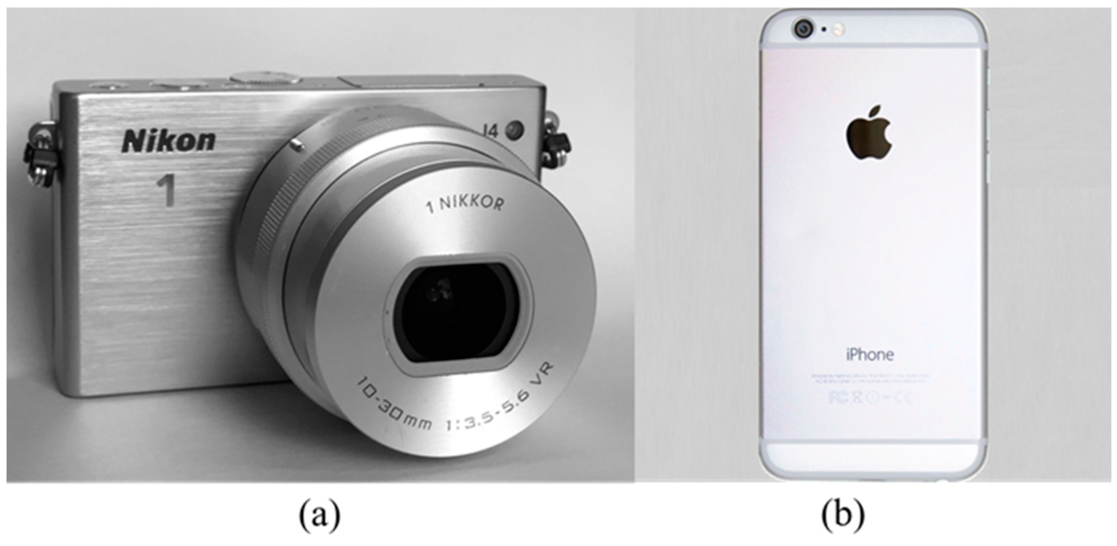
2.5. Zoom Lens Devices

Two consumer-grade zoom lens devices were used in this study, namely a Nikon 1 J4 with a 3x optical-zoom lens and an iPhone 6 mobile phone camera with a digital-zoom lens (Figure 1). In general, optical-zoom lenses change the focal length through the mechanical adjustment of the internal lens element assembly [34,39]. The implementation of digital zooming is based on in-camera image processing techniques, achieved by cropping an image down to a centered area and then enlarging the remaining portion back up to the pixel dimensions of the original [40]. Although the two approaches to zooming have fundamental differences, a common advantage shared by them both when compared to a prime lens device is the ability to fit the FOV and exclude unnecessary portions of a scene. Without loss of generality, calibrations on both types of zoom lens devices have been carried out with the same zoom lens camera model in this study. The detailed parameters of the two cameras can be seen in Table 1. It is worth noting that the minimum recording sensitivity of EXIF focal length of the three zoom lens cameras used in Zheng et al. [16] is 1 mm, comparing to 0.1 mm held by Nikon 1 J4.

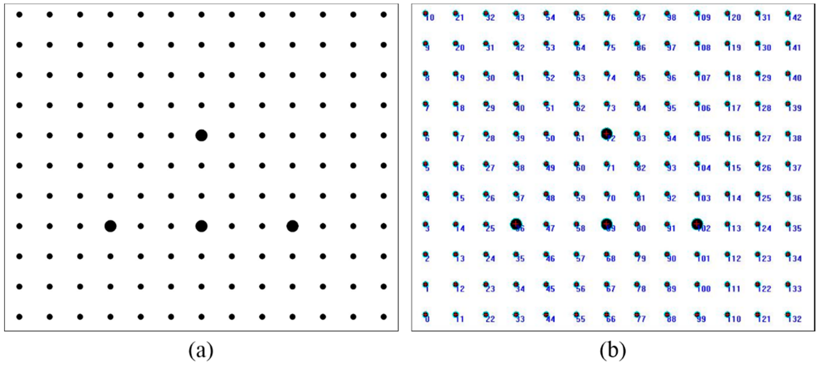
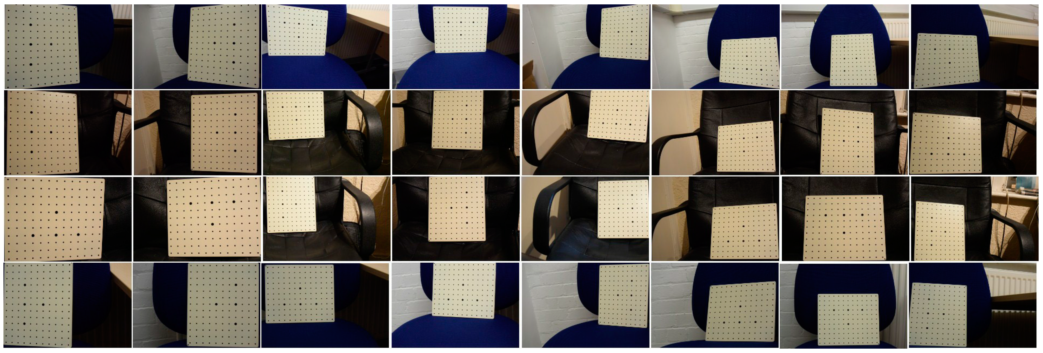
2.6. Planar Board for Calibration

A white planar alloy board with black circular targets was adopted, as illustrated in Figure 2a. The planar pattern was designed in AutoCAD and all target points were printed on the alloy board with a high precision of 20 μm. The board consists of a total of 143 (13 × 11) targets at spatial intervals of 20 mm. The diameter of all small circles is 2.5 mm and the four larger circles, each with a diameter of 7.5 mm, are used to establish the 3D Cartesian object space coordinate system. By assigning zero to the vertical coordinates, the precisely determined 3D object space coordinates of all target points can be treated as known values and the adjustment essentially becomes a Simultaneous Multi-frame Analytical Calibration (SMAC), as first proposed by Brown [41]. As targets are circular in shape and have a strong contrast against the white background, the precise extraction of target points is implemented through edge detection and ellipse fitting based on least squares methods. The presence of the four larger targets enables the automatic encoding of extracted points, an example being shown in Figure 2b.

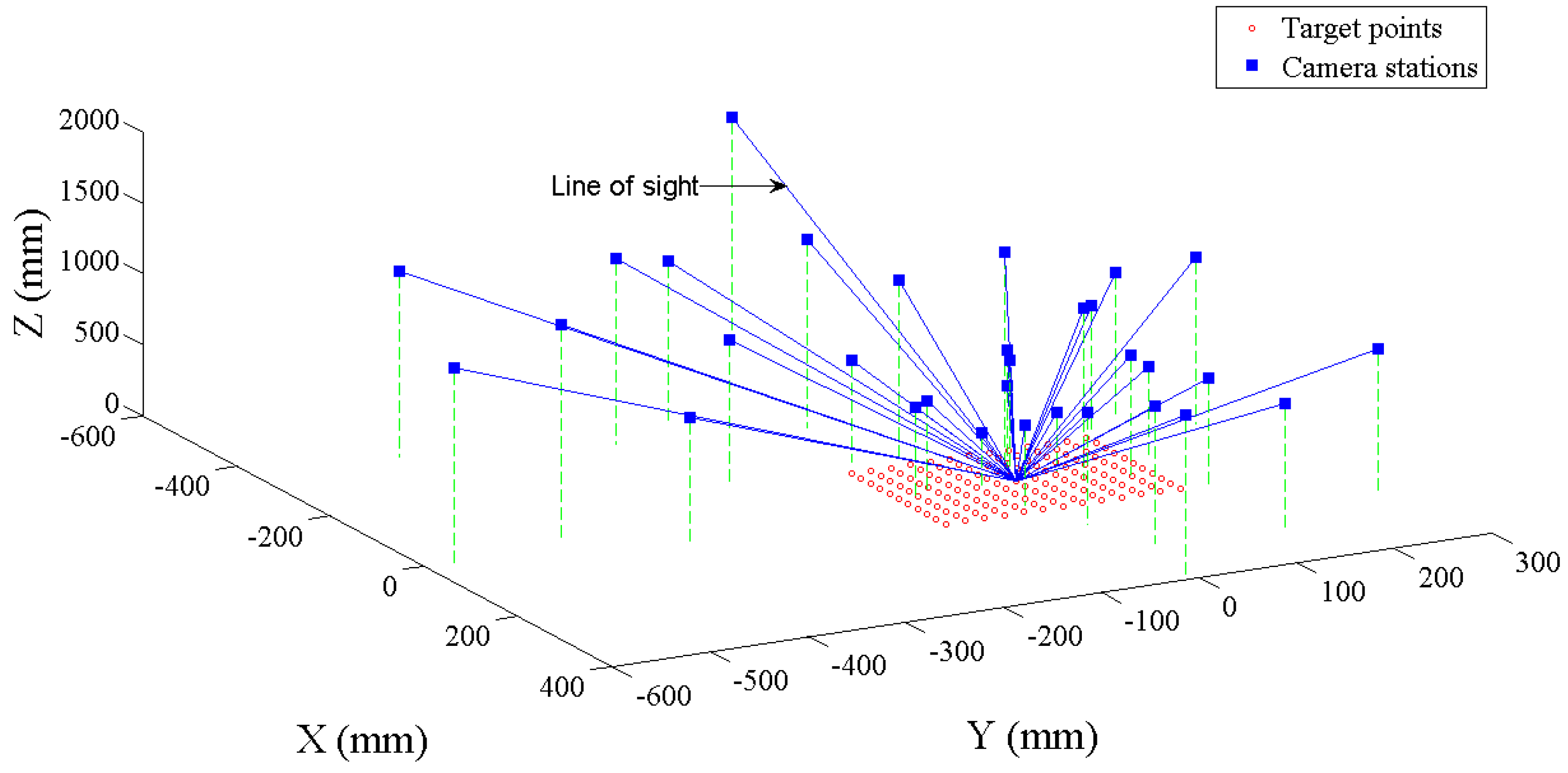
2.7. Image Geometry Configuration

Zoom lens calibrations for each camera were performed with four different focal lengths throughout the zoom range of the lens. Information about these calibrations can be seen in Table 2.
All images in all experiments were captured with the devices in auto focus mode. The internal camera distortion correction was turned off and images are entirely covered by targets. The planar board was rotated during data collection. Image thumbnails used in the calibration of the Nikon 1 J4 are shown in Figure 3 and the corresponding image network configuration is shown in Figure 4. A similar network geometry was adopted for the calibrations of the iPhone 6 camera.

3. Results

To verify the developed approach, zoom lens calibrations for the adopted devices were conducted according to the proposed method. To intuitively exhibit the variation trends, intrinsic camera parameters at several zoom settings covering the entire zoom range of each device were calculated using model coefficients solved in zoom lens calibrations. The scatter plots in Figure 5 compare the calculated intrinsic parameters and the corresponding mono-focal calibration results.
As depicted in Figure 5, some common intrinsic parameter variations were witnessed for both studied devices, despite them belonging to optical- and digital-zoom types, respectively. The principal distance shows extreme consistency between zoom lens and mono-focal calibrations. Moreover, the radial distortion parameters achieved by zoom lens calibrations approximately comply with the corresponding parameters determined by mono-focal calibration, especially the first-order radial distortion coefficient, k1. However, the principal point offsets for the two zoom lens cameras and decentering distortion parameters for the iPhone 6 do not exhibit regular changes. As reported by Tang and Fritsch [1], correlations exist between the principal point and the decentering parameters and small principal point variations may be undetectable in the calibration. Therefore, the true recovery of the principal point offsets and decentering parameters with the proposed methodology could be difficult to achieve. Overall, the intrinsic parameter variation trends illustrated in Figure 5 are approximately consistent with the findings of several previous studies [16,22,34].
In order to evaluate the measurement accuracy achievable by the proposed method, photogrammetric triangulations at three zoom settings for each device were performed, with 16 target points used as independent checkpoints. The zoom settings for accuracy evaluation were deliberately selected so as not to coincide with the aforementioned zoom lens calibrations. Within each adjustment, the intrinsic parameters calibrated by mono-focal calibrations and calculated with model coefficients of zoom lens calibrations were considered as known values. Object space coordinates of the checkpoints were computed by intersection using the corrected image coordinates and the computed extrinsic parameters in triangulation. Thereafter, the root-mean-square error (RMSE) calculated against the true 3D coordinates of all checkpoints was considered to provide a measure of the absolute accuracy. Furthermore, the root-mean-square (RMS) of the image projection residuals was also recorded. The accuracy evaluation results of mono-focal triangulation for the employed devices are summarized in Table 3.
Additionally, a further accuracy evaluation was performed, which is based on multi-focal triangulation with the proposed zoom lens camera model presented in Equation (2). Images captured at multiple zoom settings were processed in a single adjustment. Model coefficients calibrated in zoom lens calibrations were input as known values during multi-focal triangulation. The accuracies achieved by the two zoom lens cameras studied are shown in Table 4.

4. Discussion

4.1. Accuracy Assessment

As shown in Table 3, the mono-focal triangulation accuracies achieved by zoom lens calibrations degraded to some extent for both devices. The multi-focal triangulation accuracies (Table 4) were wholly superior to mono-focal measurements. Overall, the iPhone 6 outperformed the Nikon 1 J4 in terms of both mono-focal and multi-focal accuracies despite the Nikon 1 J4 camera having a higher spatial resolution than the iPhone 6 mobile camera. This somewhat surprising result can most probably be attributed to the recording precision of the EXIF focal length and the suitability of the IO parameter mathematical model.
The experimental results based on the EXIF focal length do not show serious degradation as reported by Zheng et al. [16]. The reason could be that the Nikon 1 J4 has a higher recording sensitivity (0.1 mm) of the EXIF focal length than the three devices (1 mm) used in the previous study [16]. The sequential EXIF focal lengths for the Nikon 1 J4 are illustrated in Figure 6. In addition, the iPhone 6 is fitted with a digital zoom lens and the implementation of digital zooming is based on in-cameral image processing techniques and not the movement of internal components inside a zoom lens barrel. Thus, the 35 mm equivalent focal length written in the EXIF of the iPhone 6 images could be precise.
Accuracy degradation occurs unavoidably in mono-focal and multi-focal measurements, which can be mainly attributed to two factors. Firstly, the EXIF focal length for the two studied two zoom lens cameras can be relatively precise, but slight inaccuracy is inevitable. Another degradation source could be the variation models of the intrinsic parameters. The focus effect, for example, was not taken into account in this method. Moreover, as pointed out by Läbe and Förstner [14], intrinsic parameters for digital cameras change over time. Therefore, the theoretical zoom-dependent models described in Equation (1) cannot completely express the practical variation.
The proposed approach avoids solving intrinsic parameters at each focal length setting and all coefficients are determined in a single adjustment. Moreover, object-space coordinates of target points are constrained in the adjustment. The approach therefore places a relatively low requirement on the imaging network geometry compared to that based on the strategy of conducting mono-focal calibrations followed by modeling. As a result, the zoom lens camera model can be successfully recovered even though only seven to eight images were captured per zoom lens setting in each experiment.

4.2. Demonstration

Terrestrial Laser Scanning (TLS) and photogrammetry are generally regarded as complementary techniques, and it is recognized that their integration can lead to more accurate and complete products [42,43]. In this study, a Leica Geosystems P20 terrestrial laser scanner was used to acquire a point cloud of the façade of the King Edward VII Building on Newcastle University’s main campus. The point cloud density was set as 0.8 mm at 10 m range, with the highest quality mode selected. As the building façade is a relatively simple structure of regular size, only one scan was sufficient to acquire full coverage.
The Nikon 1 J4 camera and the iPhone 6 mobile phone were used to acquire imagery of the façade at different focal lengths. For each device, one image was captured using a focal length appropriate to capture the entire building façade, and a second image was acquired at a longer focal length, focused on an intricate central feature, a coat of arms (see Figure 7). All images were acquired from approximately the same location, directly adjacent to the TLS location. The intrinsic parameters for each image were computed using Equation (1) with the EXIF focal length of each image and pre-calibrated model coefficients via the ZLC process.
In order to obtain the EO parameters of each image, sufficient conjugate reference points were manually selected on both the point cloud and corresponding image. Reference points for each co-registration are marked as circular dots and labeled with numbers in Figure 7f–i. The EO parameters were computed by the following procedure: (a) a 3D direct linear transformation (DLT) [44] was performed and the EO parameters were extracted from the 11 coefficients of DLT, which requires at least six reference points [45]; (b) iterative space resection was executed to refine the EO parameters.
Once EO parameters of each image were determined, the co-registration of both the point cloud and image was implemented based on the collinearity equations with lens distortion correction terms. 3D space point coordinates were converted to an image plane and the color was assigned to each point in the cloud using nearest neighbor interpolation. In this application, the shorter focal length image was used to first texture the entire point cloud. The initial textured point cloud was then updated with the longer focal length image. Figure 7 displays all photos and compares the final textured point cloud products.
As illustrated in Figure 7, the point cloud textured using the longer focal length image displays improved clarity over its shorter focal length counterpart image for the Nikon 1 J4. The reason is that both images were acquired from approximately the same position. Thus, the longer focal length image has a higher spatial resolution than the shorter one. Conversely, the two point clouds textured with different focal length imagery from the iPhone 6 are quite similar in clarity, which can be explained by the principles of digital zooming. As explained in Section 4.1, digital zooming is based on built-in image processing algorithms and the practical spatial resolution is not physically changed during zoom variations. Additionally, the Nikon 1 J4 results show clearer texture than the iPhone 6, since the Nikon 1 J4 has a higher spatial resolution.
With respect to the geometric performance, the co-registration accuracies of the point cloud and each image were appraised by the RMS of the image projection residuals of all reference points in the final spatial resection. The RMS of image residuals (in pixels) of the textured point cloud (a), (b), (j), and (k) in Figure 7 were 1.64, 1.21, 1.17, and 1.43, respectively. The co-registrations RMS values were larger than those shown in Table 3 mainly due to the unavoidable inaccuracy of manual reference point selection with respect to the automatic detection of target points on the planar board. Nevertheless, this result demonstrates the feasibility of the proposed method for the fusion of TLS point clouds and optical images using an optical or digital zoom lens camera with moderate precision.

5. Conclusions

This study has proposed a complete, flexible zoom lens camera model, and presented a comprehensive calibration method based upon this concept. Using a planar board with coded targets extracted from imagery taken at different zoom settings, the zoom lens model for a camera can be recovered. The following conclusions are reached on the basis of the experimental results and related analysis:
(1)
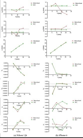
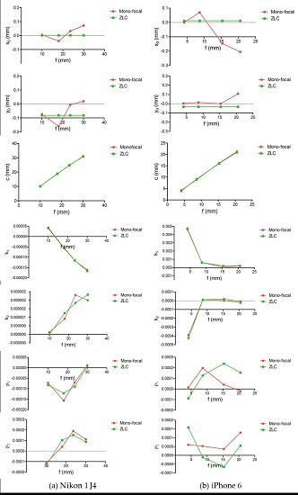
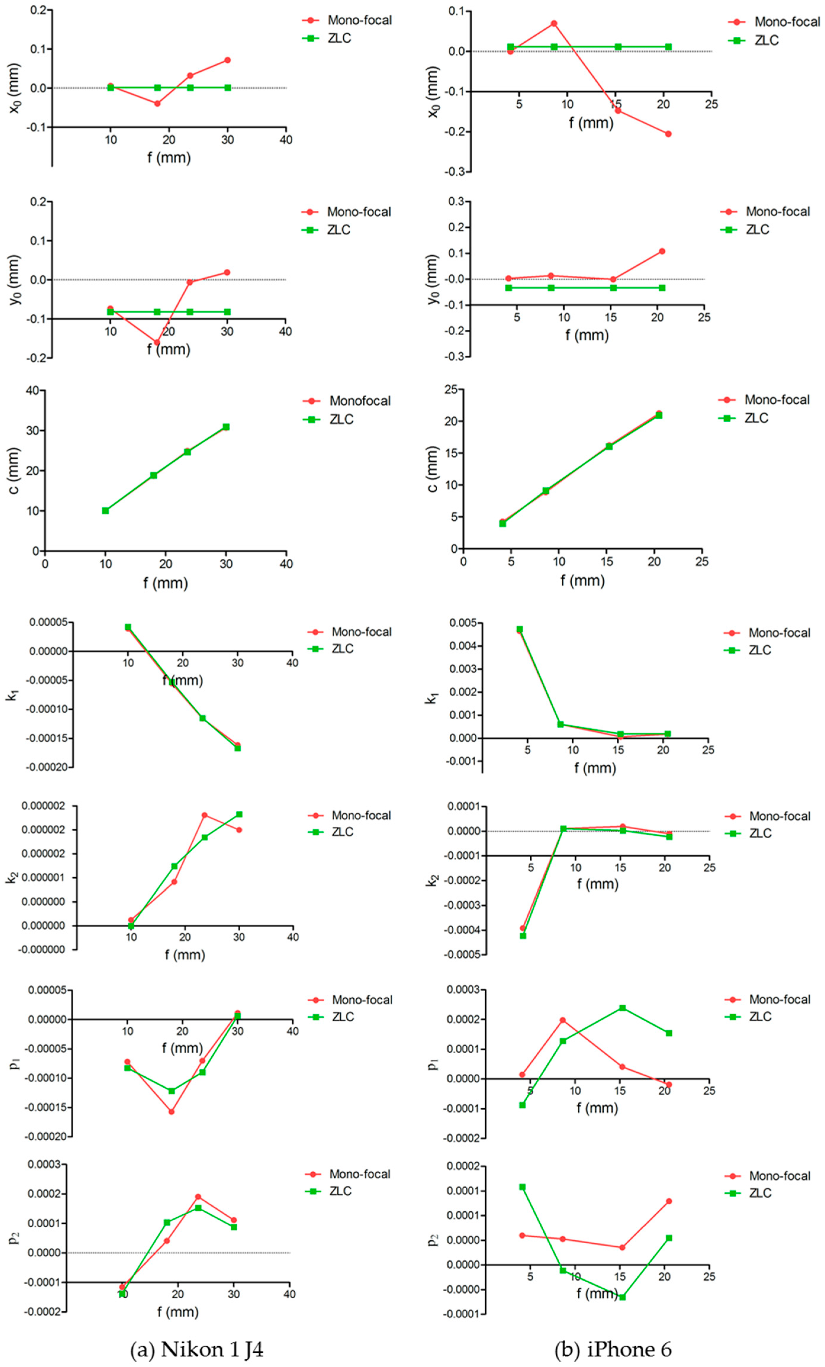
Experiments have been performed on a Nikon 1 J4 and an iPhone 6 mobile phone camera, which support the feasibility and validity of the proposed method for calibrating both optical- and digital-zoom cameras. In other words, the fundamental mathematical model, i.e., collinearity condition equations with zoom-related intrinsic parameters, is feasible for zoom lens calibration. The proposed camera model can be more generally applicable than zoom- and focus-dependent models, as the latter cannot be applied to zoom lens cameras without recording focus information.
(2)
The relative accuracies evaluated via a set of mono-focal triangulations, with support of model coefficients of intrinsic parameters achieved by zoom lens calibrations, are better than 1:6300 for the two employed devices. With regard to the multi-focal triangulation accuracy achieved in this study, it is 1:11,300 for the Nikon 1 J4, while the iPhone 6 reaches up to 1:16,100. This fact demonstrates that it is practicable to use a zoom lens camera either at a single zoom setting or at any combination of multiple settings, which undoubtedly improves the flexibility of a zoom lens camera in practice.
(3)
Experimental results achieved by the optical zoom lens camera did not exhibit the same extent of accuracy degradation as reported by Zheng et al. [16] since the Nikon 1 J4 with a 3x optical-zoom lens has a higher EXIF recording sensitivity than any of the three zoom lens cameras utilized by Zheng et al. [16]. This suggests that the EXIF recording ability varies among different devices and the zoom-dependent camera model based on a higher sensitivity of EXIF focal length recording can be accurate and avoid serious photogrammetric accuracy degradation. Besides, the use of the EXIF focal length overcomes the inconvenience of the manual recording using artificial rulers [16].
(4)
The practical application of texturing a TLS point cloud with two calibrated optical zoom lens images has demonstrated the advantages and flexibility of adjusting spatial resolution using an optical zoom lens over a digital zoom lens for photorealistic modelling purposes.
On the basis of these conclusions, the presented zoom lens calibration approach facilitates a range of applications to which photogrammetry is suited. The mono-focal and multi-focal measurement accuracies achieved by zoom lens calibration results for both of the adopted devices may be regarded as satisfactory for many applications such as robotic exploration, hazard monitoring, heritage recording, and forensic applications [20,34,46,47].

Acknowledgments

This research was supported by a China Scholarship Council (CSC) Studentship, No. 201506270153 held by Zheng Wang at Newcastle University, UK. Part of this work was supported by the UK Science and Technology Facilities Council through the PAFiC project (Ref: ST/N006801/1) and by Hunan Province Key Laboratory of Coal Resources Clean-Utilization and Mine Environment Protection, Hunan University of Science and Technology (Ref: E21608).

Author Contributions

Zheng Wang realized his Master’s thesis project entitled “Zoom lens calibration and its accuracy analysis in close-range photogrammetry” in the school of Remote Sensing Science and Information Engineering, Wuhan University, under the supervision of Shunyi Zheng. This article is based on research performed subsequent to this earlier project. The initial experiments were realized with the help of Rongyong Huang. The subsequent experiments were performed at Newcastle University, under the supervision of Jon Mills who also substantially improved this article. Wen Xiao participated in the data collection and contributed to the writing of this paper. Zhenhong Li gave constructive suggestions about the application and contributed to the writing of this paper.

Conflicts of Interest

The authors declare no conflict of interest.

References

  1. Schmidt, A.; Sun, L.; Aragon-Camarasa, G.; Siebert, J.P. The Calibration of the Pan-Tilt Units for the Active Stereo Head. In Image Processing and Communications Challenges 7; Springer: Cham, Switzerland, 2016; pp. 213–221. [Google Scholar]
  2. Taketomi, T.; Okada, K.; Yamamoto, G.; Miyazaki, J.; Kato, H. Camera pose estimation under dynamic intrinsic parameter change for augmented reality. Comput. Graph. 2014, 44, 11–19. [Google Scholar] [CrossRef]
  3. Salvagnini, P.; Pernici, F.; Cristani, M.; Lisanti, G.; Del Bimbo, A.; Murino, V. Non-myopic information theoretic sensor management of a single pan–tilt–zoom camera for multiple object detection and tracking. Comput. Vis. Image Underst. 2015, 134, 74–88. [Google Scholar] [CrossRef]
  4. Fraser, C.S. Digital camera self-calibration. ISPRS J. Photogramm. Remote Sens. 1997, 52, 149–159. [Google Scholar] [CrossRef]
  5. Tsai, R.Y. A versatile camera calibration technique for high-accuracy 3d machine vision metrology using off-the-shelf tv cameras and lenses. IEEE J. Robot. Autom. 1987, 3, 323–344. [Google Scholar] [CrossRef]
  6. Schenk, T. Introduction to Photogrammetry; The Ohio State University: Columbus, OH, USA, 2005. [Google Scholar]
  7. McGlone, J.C. Manual of Photogrammetry; American Society of Photogrammetry: Bethesda, MD, USA, 2013. [Google Scholar]
  8. Remondino, F.; Fraser, C. Digital camera calibration methods: Considerations and comparisons. Int. Arch. Photogramm. Remote Sens. Spat. Inf. Sci. 2006, 36, 266–272. [Google Scholar]
  9. Kannala, J.; Heikkilä, J.; Brandt, S.S. Geometric Camera Calibration. In Wiley Encyclopedia of Computer Science and Engineering; John Wiley and Sons, Inc.: Somerset, NJ, USA, 2008. [Google Scholar]
  10. Clarke, T.A.; Fryer, J.G. The development of camera calibration methods and models. Photogramm. Rec. 1998, 16, 51–66. [Google Scholar] [CrossRef]
  11. Fraser, C. Multiple focal setting self-calibration of close-range metric cameras. Photogramm. Eng. Remote Sens. 1980, 46, 1161–1171. [Google Scholar]
  12. Lichti, D.D.; Qi, X.J.; Ahmed, T. Range camera self-calibration with scattering compensation. ISPRS J. Photogramm. Remote Sens. 2012, 74, 101–109. [Google Scholar] [CrossRef]
  13. Brown, D.C. Close-range camera calibration. Photogramm. Eng. 1971, 37, 855–866. [Google Scholar]
  14. Läbe, T.; Förstner, W. Geometric Stability of Low-Cost Digital Consumer Cameras. In Proceedings of the 20th ISPRS Congress, Istanbul, Turkey, 12–23 July 2004; pp. 528–535.
  15. Shortis, M.; Bellman, C.; Robson, S.; Johnston, G.; Johnson, G. Stability of Zoom and Fixed Lenses Used with Digital SLR Cameras. In Proceedings of the ISPRS Commission V Symposium of Image Engineering and Vision Metrology, Dresden, Germany, 25–27 September 2006; pp. 285–290.
  16. Zheng, S.; Wang, Z.; Huang, R. Zoom lens calibration with zoom- and focus-related intrinsic parameters applied to bundle adjustment. ISPRS J. Photogramm. Remote Sens. 2015, 102, 62–72. [Google Scholar] [CrossRef]
  17. Chen, J.; Dowman, I.; Li, S.; Li, Z.; Madden, M.; Mills, J.; Paparoditis, N.; Rottensteiner, F.; Sester, M.; Toth, C. Information from imagery: Isprs scientific vision and research agenda. ISPRS J. Photogramm. Remote Sens. 2016, 115, 3–21. [Google Scholar] [CrossRef]
  18. Sobel, I. On calibrating computer controlled cameras for perceiving 3-D scenes. Artif. Intell. 1974, 5, 185–198. [Google Scholar] [CrossRef]
  19. Krotkov, E.P. Exploratory Visual Sensing for Determining Spatial Layout with an Agile Stereo Camera System; University of Pennsylvania: Philadelphia, PA, USA, 1987. [Google Scholar]
  20. Fraser, C.; Al-Ajlouni, S. Zoom-dependent camera calibration in digital close-range photogrammetry. Photogramm. Eng. Remote Sens. 2006, 72, 1017–1026. [Google Scholar] [CrossRef]
  21. Kim, D.; Oh, J.; Sohn, K.; Shin, H. Automatic radial distortion correction in zoom lens video camera. J. Electron. Imaging 2010, 19. [Google Scholar] [CrossRef]
  22. Alvarez, L.; Gómez, L.; Henríquez, P. Zoom dependent lens distortion mathematical models. J. Math. Imaging Vis. 2012, 44, 480–490. [Google Scholar] [CrossRef]
  23. Galego, R.; Bernardino, A.; Gaspar, J. Auto-Calibration of Pan-Tilt Cameras Including Radial Distortion and Zoom. In Advances in Visual Computing; Springer: Berlin/Heidelberg, Germany, 2012; pp. 169–178. [Google Scholar]
  24. Wu, Z.; Radke, R.J. Keeping a pan-tilt-zoom camera calibrated. IEEE Trans. Pattern Anal. Mach. Intell. 2013, 35, 1994–2007. [Google Scholar] [CrossRef] [PubMed]
  25. Sarkis, M.; Senft, C.T.; Diepold, K. Calibrating an automatic zoom camera with moving least squares. IEEE Trans. Autom. Sci. Eng. 2009, 6, 492–503. [Google Scholar] [CrossRef]
  26. Willson, R.G. Modeling and Calibration of Automated Zoom Lenses; Photonics for Industrial Applications; International Society for Optics and Photonics: Bellingham, WA, USA, 1994; pp. 170–186. [Google Scholar]
  27. Tarabanis, K.; Tsai, R.Y.; Goodman, D.S. Modeling of a Computer-Controlled Zoom Lens. In Proceedings of the International Conference on Robotics and Automation, Nice, France, 12–14 May 1992; pp. 1545–1551.
  28. Burner, A.W. Zoom lens calibration for wind tunnel measurements. Video Metrics IV 1995, 2598, 19–33. [Google Scholar]
  29. Wiley, A.G.; Wong, K.W. Geometric calibration of zoom lenses for computer vision metrology. Photogramm. Eng. Remote Sens. 1995, 61, 69–74. [Google Scholar]
  30. Li, M.; Lavest, J.-M. Some aspects of zoom lens camera calibration. IEEE Trans. Pattern Anal. Mach. Intell. 1996, 18, 1105–1110. [Google Scholar]
  31. Chen, Y.-S.; Shih, S.-W.; Hung, Y.-P.; Fuh, C.-S. Simple and efficient method of calibrating a motorized zoom lens. Image Vis. Comput. 2001, 19, 1099–1110. [Google Scholar] [CrossRef]
  32. Ahmed, M.T.; Farag, A.A. A neural approach to zoom-lens camera calibration from data with outliers. Image Vis. Comput. 2002, 20, 619–630. [Google Scholar] [CrossRef]
  33. Fraser, C.; Cronk, S.; Stamatopoulos, C. Implementation of zoom-dependent camera calibration in close-range photogrammetry. ISPRS-Int. Arch. Photogramm. Remote Sens. Spat. Inf. Sci. 2012, 1, 15–19. [Google Scholar] [CrossRef]
  34. Wu, B.; Hu, H.; Zhu, Q.; Zhang, Y. A flexible method for zoom lens calibration and modeling using a planar checkerboard. Photogramm. Eng. Remote Sens. 2013, 79, 555–571. [Google Scholar] [CrossRef]
  35. Fraser, C.S. Automatic camera calibration in close range photogrammetry. Photogramm. Eng. Remote Sens. 2013, 79, 381–388. [Google Scholar] [CrossRef]
  36. Agapito, L.; Hayman, E.; Reid, I. Self-calibration of rotating and zooming cameras. Int. J. Comput. Vis. 2001, 45, 107–127. [Google Scholar] [CrossRef]
  37. Tang, R.F.; Fritsch, D. Correlation analysis of camera self-calibration in close range photogrammetry. Photogramm. Rec. 2013, 28, 86–95. [Google Scholar] [CrossRef]
  38. Zhang, Y.; Zhang, Z.; Zhang, J. Camera Calibration Technique with Planar Scenes; Electronic Imaging 2003; International Society for Optics and Photonics: Bellingham, WA, USA, 2003; pp. 291–296. [Google Scholar]
  39. Malacara, D.; Malacara, Z. Handbook of Lens Design; Marcel Dekker: New York, NY, USA, 1994; Volume 1. [Google Scholar]
  40. Freeman, M. The Complete Guide to Digital Photography; Sterling Publishing Company, Incorporated: New York, NY, USA, 2003. [Google Scholar]
  41. Brown, D.C. Advanced Methods for the Calibration of Metric Cameras; DTIC Document: Fort Belvoir, VA, USA, 1968. [Google Scholar]
  42. Leberl, F.; Irschara, A.; Pock, T.; Meixner, P.; Gruber, M.; Scholz, S.; Wiechert, A. Point clouds: Lidar versus 3d vision. Photogramm. Eng. Remote Sens. 2010, 76, 1123–1134. [Google Scholar] [CrossRef]
  43. Ackermann, F. Airborne laser scanning present status and future expectations. ISPRS J. Photogramm. Remote Sens. 1999, 54, 64–67. [Google Scholar] [CrossRef]
  44. Abdel-Aziz, Y. Direct Linear Transformation from Comparator Coordinates in Close-Range Photogrammetry. In ASP Symposium on Close-Range Photogrammetry; University of Illinois: Champaign, IL, USA, 1971. [Google Scholar]
  45. Heikkila, J.; Silven, O. A Four-Step Camera Calibration Procedure with Implicit Image Correction. In Proceedings of the IEEE Computer Society Conference on Computer Vision and Pattern Recognition, San Juan, PR, USA, 17–19 June 1997; pp. 1106–1112.
  46. Luhmann, T.; Robson, S.; Kyle, S.; Harley, I. Close Range Photogrammetry: Principles, Methods and Applications; Whittles: Dunbeath, UK, 2006. [Google Scholar]
  47. Fryer, J.; Mitchell, H.; Chandler, J.H. Applications of 3D Measurement from Images; Whittles Publishing: Dunbeath, UK, 2007. [Google Scholar]
Figure 1. (a) Nikon 1 J4 camera with a 3x optical zoom lens; (b) iPhone 6 mobile phone camera.
Remotesensing 09 00244 g001
Figure 2. (a) Target pattern of the planar board used for zoom lens calibration; (b) An example of automatic extraction and encoding of target points.
Remotesensing 09 00244 g002
Figure 3. Images used for zoom lens calibration of Nikon 1 J4.
Remotesensing 09 00244 g003
Figure 4. Image network configuration for zoom lens calibration of the Nikon 1 J4.
Remotesensing 09 00244 g004
Figure 5. Comparison of intrinsic parameters determined by zoom lens calibrations (denoted as ZLC) and mono-focal calibrations for the two cameras: (a) Nikon 1 J4 and (b) iPhone 6.
Remotesensing 09 00244 g005
Figure 6. The sequential EXIF focal lengths for the Nikon 1 J4.
Remotesensing 09 00244 g006
Figure 7. Photos and textured point cloud products. (a) Nikon 1 J4 image (f = 16.8 mm); (b) Nikon 1 J4 image (f = 29.4 mm); (c) iPhone 6 image (f35 = 46 mm); (d) iPhone 6 image (f35 = 92 mm); (e) The original point cloud of the central feature of the King Edward VII façade. (fi) Point clouds of the King Edward VII façade, textured with images (a), (b), (c), (d) respectively; (jm) The detailed texture on different point clouds.
Remotesensing 09 00244 g007
Table 1. Physical properties of the two zoom lens devices employed.
CameraZoom lens
ProductResolution (Pixels)Pixel SizeProductZoom Typef35 1 (mm)f 2 (mm)Max Aperture
Nikon 1 J45232 × 34882.52 µmNikkor kit lensOptical27–8110–30F/3.5–5.6
iPhone 63264 × 24481.5 µmApple iSightDigital29–1454.1–20.5F/2.2
1 f35 is the 35 mm equivalent focal length automatically written in the EXIF header when a photo is taken; 2 f is the focal length for zoom lens calibration. For the Nikon 1 J4, f is directly recorded in the EXIF header. For the iPhone 6, the physical pixel size is assumed unchanged during zooming operations, thus f is converted from f35 via the expression f = f35/7.07.
Table 2. Image information for each zoom lens calibration.
Zoom Setting (f: mm)Images/SettingTotal Images
Nikon 1 J4{10.0, 18.0, 23.6, 30.0}832
iPhone 6{4.1, 8.6, 15.3, 20.5}728
Table 3. Zoom lens vs mono-focal calibrations in terms of derived accuracy.
f (mm)H 1 (mm)RMS of Image Residuals (Pixel)RMSE of XY Coordinates (mm)RMSE of Z Coordinates (mm)Relative Accuracy 2 (1:x)
Nikon 1 J4Mono-focal15.78000.760.0500.05710,500
21.010300.530.0430.09210,200
26.011800.900.0450.07813,100
ZLC15.78001.270.0850.0936300
21.010300.730.0550.08610,100
26.011800.930.0430.08812,100
iPhone 6Mono-focal6.79000.390.0480.07310,300
12.015200.390.0440.07018,400
18.119900.510.0500.07122,900
ZLC6.79000.920.0650.0749100
12.015200.440.0450.06818,400
18.119900.660.0510.10217,500
1 H is the average perpendicular distance from the camera stations to the planar board; 2 Relative accuracy is defined as RMSE of 3D coordinates: H = 1:x.
Table 4. Multi-focal triangulation accuracy evaluation.
f (mm)H (mm)RMS of Image Residuals (Pixel)RMSE of XY Coordinates (mm)RMSE of Z Coordinates (mm)Relative Accuracy (1:x)
Nikon 1 J4_ZLC{15.7, 21.0, 26.0}10001.000.0470.07511,300
iPhone 6_ZLC{6.7, 12.0, 18.1}15100.710.0480.08116,100

