
Spin Laser Local Oscillators for Homodyne Detection in Coherent Optical Communications

Research Institute of Electrical Communication, Tohoku University, Sendai 980-8577, Japan
*
Author to whom correspondence should be addressed.
Micromachines 2021, 12(5), 573; https://0-doi-org.brum.beds.ac.uk/10.3390/mi12050573
Submission received: 12 April 2021
/
Revised: 6 May 2021
/
Accepted: 14 May 2021
/
Published: 18 May 2021
(This article belongs to the Special Issue Spin-Photonic Devices and Its Applications)
Abstract
:We numerically investigate spin-controlled vertical-cavity surface-emitting lasers (spin-VCSELs) for local oscillators, which are based on an injection locking technique used in coherent optical communications. Under the spin polarization modulation of an injection-locked spin-VCSEL, frequency-shifted and phase-correlated optical sidebands are generated with an orthogonal polarization against the injection light, and one of the sidebands is resonantly enhanced due to the linear birefringence in the spin-VCSEL. We determine that the peak strength and peak frequency in the spin polarization modulation sensitivity of the injection-locked spin-VCSEL depend on detuning frequency and injection ratio conditions. As a proof of concept, 25-Gbaud and 16-ary quadrature amplitude modulation optical data signals and a pilot tone are generated, and the pilot tone is used for the injection locking of a spin-VCSEL. An orthogonally-polarized modulation sideband generated from the injection-locked spin-VCSEL is used as a frequency-shifted local oscillator (LO). We verify that the frequency-shifted LO can be used for the homodyne detection of optical data signals with no degradation. Our findings suggest a novel application of spin-VCSELs for coherent optical communications.
1. Introduction
Coherent optical communication systems have been gaining attention due to their benefits in a coherent detection scheme in combination with high-speed digital signal processing (DSP) for improving signal detection accuracy, frequency utilization efficiency, and tolerance to signal distortion [1,2]. In these systems, optical data signals are received in a coherent manner using a local oscillator (LO), and a coherent receiver in which in-phase and quadrature-phase components of the optical data signals can be detected. Thus, advanced modulation formats such as quadrature amplitude modulation (QAM), which have a high frequency utilization efficiency compared with the conventional on-off keying, can be used. A synchronization between the LO and the optical data signals can be obtained by using phase estimation techniques based on DSP at the receiver side [3,4,5]. However, large computations are required of the DSP when the modulation format is complex due to multi-level patterns, so hardware-based synchronization schemes are ideal in this case. Optical phase-locked loop (OPLL) circuits have been widely investigated for obtaining the synchronization in coherent optical communications [6,7]. However, conventional OPLL circuits are generally complex, and obtaining a wide bandwidth for the feedback loop is difficult. Additionally, both the OPLL and the DSP-based phase estimation schemes require narrow linewidth lasers for reducing the phase noise of the optical data signals, which leads to an increase in system cost.
We consider an injection locking scheme in which a semiconductor laser operating as an LO is injection-locked to a pilot tone transmitted with optical data signals. Synchronization can be carried out easily as this scheme does not require a narrow linewidth laser on the receiver side [8,9,10]. Liu et al. reported on the injection locking of a semiconductor laser to a residual optical carrier of orthogonal frequency division multiplexing signals and homodyne detection of the signals [9]. Although the use of the residual optical carrier for the injection locking is straightforward for the homodyne detection, a guard band in the optical data signals and detuned operation of a dual-parallel Mach–Zehnder modulator (DP-MZM), which leads to distortion of the optical data signals, are necessary. To circumvent these drawbacks, a combination of the injection-locked LO and a frequency shifter have been reported [10]. Hereafter, we refer to such an LO as a frequency-shifted LO.
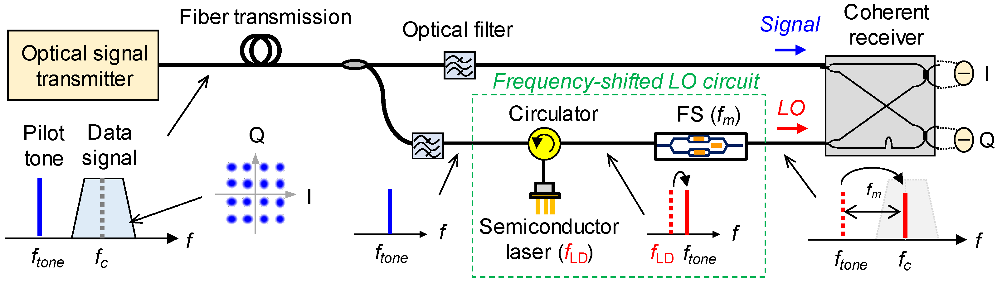
A schematic of the coherent optical communication system based on the frequency-shifted LO is shown in Figure 1. A pilot tone is added to data signals on the transmitter side and used for the injection locking of a semiconductor laser on the receiver side. The injection-locked semiconductor laser can be used as an LO for heterodyne detection with a frequency separation of |ftone − fc|, where ftone and fc are pilot tone frequency and center frequency of the data signals, respectively. However, heterodyne detection requires wide-band electrical components, which is unsuitable for high-baud-rate communications. As shown in Figure 1, homodyne detection is feasible when the frequency of the injection-locked semiconductor laser is shifted by fm using a frequency shifter (FS) to compensate for the frequency separation of |ftone − fc|. This method is applicable to the homodyne detection in the coherent optical communications and to carrier frequency conversion in beyond-5G wireless communications [11]. However, the configuration of a frequency-shifted LO, which requires a costly and complex FS, can be further simplified.
An approach to simplifying the frequency-shifted LO is to use the modulation sideband of directly modulated lasers (DMLs) to shift the LO frequency without using the FS. In particular, the photon-photon resonance effect, which occurs in external cavity structures and increases modulation sensitivity at high frequencies [12,13,14,15], may be useful for generating modulation sidebands with a high frequency separation. However, one of the modulation sidebands needs to be extracted by using a narrow-band optical filter, which is unsuitable for simplifying the configuration.
The approach we propose in this study is the use of spin-controlled vertical-cavity surface-emitting lasers (spin-VCSELs) [16,17,18,19,20,21,22,23]. The up-spin and down-spin electron densities in an active region can be freely modulated when ferromagnetic electron spin injectors for each spin-polarized electron are fabricated [24,25]. This results in the unique spin polarization modulation in which the difference between up-spin and down-spin electron densities is modulated while the total electron density kept constant. The spin polarization modulation leads to an increase in modulation sensitivity at high frequencies depending on linear birefringence in a spin-VCSEL [26,27,28] and orthogonally-polarized modulation sidebands [29]. Thus, a lasing frequency of the spin-VCSEL injection-locked to the pilot tone may be directly shifted with high efficiency and separated from the generated sidebands by using a simple polarization beam splitter.
In this study, we numerically investigate an application of spin-VCSELs to the frequency-shifted LO for coherent optical communications. As a proof of concept, we verify that an orthogonally-polarized modulation sideband generated by the spin polarization modulation of the injection-locked spin-VCSEL can be used as the frequency-shifted LO for the pilot-tone-assisted homodyne detection of 25-Gbaud 16-QAM signals.
2. Methods
2.1. Proposed Concept
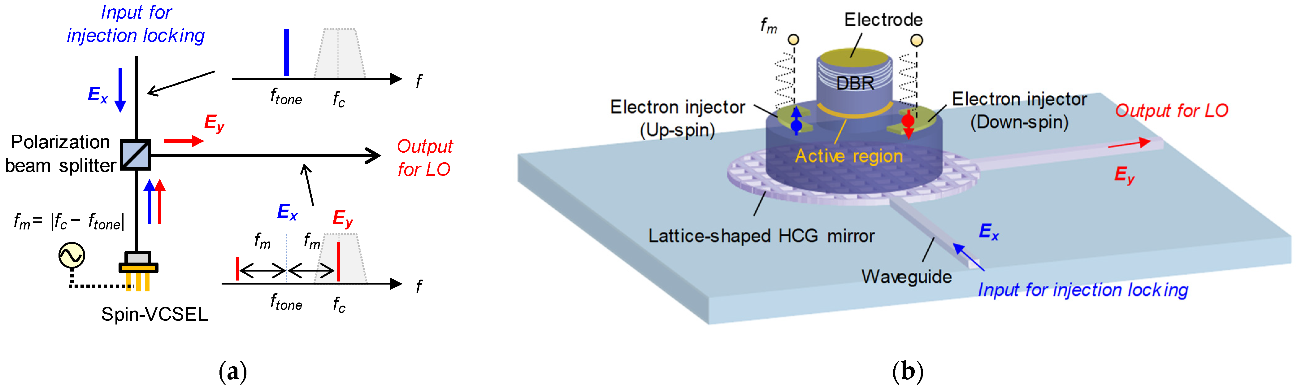
Figure 2a shows the proposed concept of frequency-shifted LOs based on injection-locked spin-VCSELs. The spin polarization of injected electrons into a spin-VCSEL is directly modulated by a sinusoidal signal under the injection locking to an input light with a linear polarization (x polarization in this case). Since modulation sidebands generated by the spin polarization modulation have orthogonal polarization against the optical carrier (DC lasing light component), the sidebands can be easily separated from the optical carrier by using a polarization beam splitter without a narrow-band optical filter. Additionally, one of the sidebands can be selectively enhanced by controlling the linear birefringence of the spin-VCSEL [29]. Therefore, we use the stronger sideband as a frequency-shifted LO for the homodyne detection of optical data signals. An example device structure of the frequency-shifted LO with an integrated configuration is illustrated in Figure 2b. The spin-VCSEL is integrated on a silicon photonics platform, and bottom of the VCSEL’s mirror consists of a lattice-shaped high-index contrast grating (HCG) instead of a conventional distributed Bragg reflector (DBR). The HCG can have a variety of characteristics such as a high-reflectivity and wide-band mirror, depending on its structure [30]. The lattice-shaped HCG can switch input/output port waveguides in accordance with the polarization of vertically injected light [31], so the polarization beam splitter in Figure 2a may be integrated with the HCG. Although obtaining a high polarization extinction ratio for each output port is challenging, the hybrid integration of the spin-VCSEL will be ideal for practical use.
2.2. Simulation Model
The spin-flip model [32] has been used for analyzing novel features of spin-VCSELs [33,34,35,36,37,38]. We used the following spin-flip rate equations, including an external light injection for simulating injection-locked spin-VCSELs and frequency-shifted LOs in coherent optical communication systems:
where E+ and E− are electric fields for right-handed (σ+) and left-handed (σ−) circular polarization modes, and N+ and N− are up-spin and down-spin electron densities. Electric fields with x and y polarizations (Ex and Ey) are expressed as Ex = (E+ + E−)/2 and Ey = −j(E+ − E−)/2. Ei is an electric field of the injection light with x polarization, and its value was set considering a parameter of injection ratio (IR) defined as IR = |Ei|2/(|E+|2 + |E−|2). Definitions and values of other parameters are shown in Table 1. The parameter values were taken from 1.55-μm InAlGaAs VCSELs fabricated by RayCan Co., Ltd. (Suzhou, China) [39,40,41].
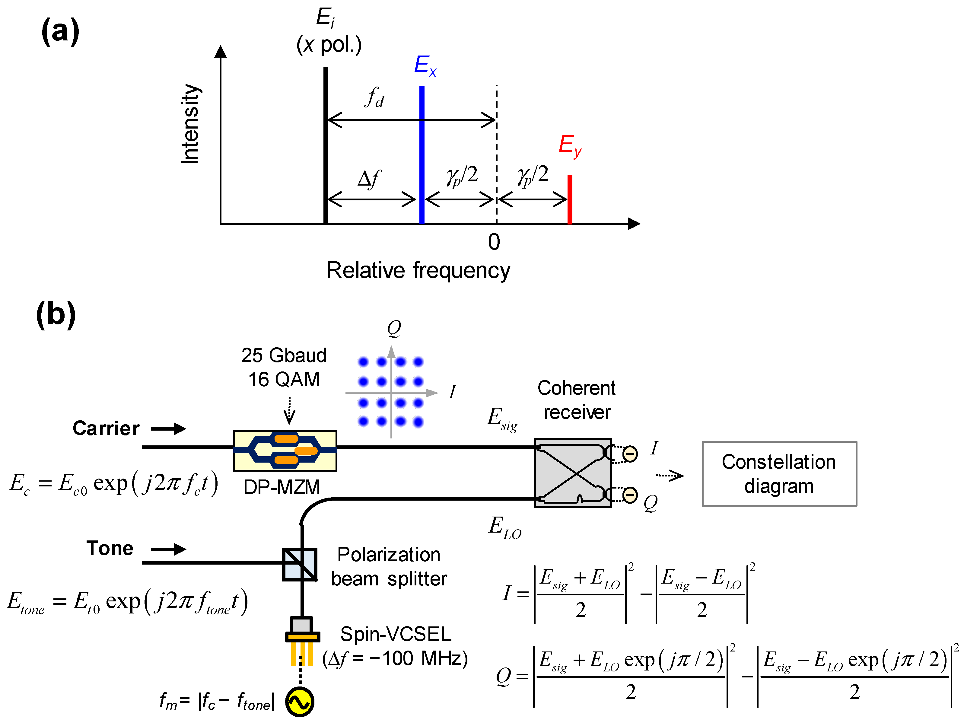
The spin polarization modulation responses of the injection-locked spin-VCSEL and a proof-of-concept simulation were investigated using Equations (1) and (2). As shown in Figure 3a, we assume that the free-running spin-VCSEL is lasing with x polarization when injected electrons are not spin-polarized, and a detuning frequency of Ei relative to Ex is defined as ∆f. Under several injection locking conditions, the spin polarization of the spin-VCSEL was modulated by sinusoidal signals with frequencies of fm, and Im of 0.1 × Ith was used for analyzing small signal responses. Then, we evaluated the corresponding modulation responses of degree of circular polarization (|E+|2 − |E−|2)/(|E+|2 + |E−|2). The concept of frequency-shifted LOs based on injection-locked spin-VCSELs was verified using the configuration shown in Figure 3b. Optical data signals with a 25-Gbaud 16-QAM pattern were generated by modulating an optical carrier (Ec) with a DP-MZM model in [42]. A pilot tone (Etone) was used for injection locking of the spin-VCSEL with ∆f of −100 MHz. This slight detuning was to verify evident injection locking, i.e., a tight synchronization between the optical data signals and the frequency-shifted LO. Both fm and the frequency difference between the optical carrier and the pilot tone (fc − ftone) were set to 50 GHz, and Im of 1 × Ith was used for strong sideband generation. The optical data signals and modulation sidebands extracted from a polarization beam splitter (i.e., Ey component) are referred to as Esig and ELO, respectively. A coherent receiver with a 90° hybrid was used for the homodyne detection which extracts in-phase (I) and quadrature-phase (Q) components of the optical data signals. Finally, I and Q signals were evaluated in a constellation diagram and its error vector magnitude (EVM). Note that 16-QAM symbols in the constellation diagram will rotate if injection locking is not achieved due to the 100-MHz detuning. An ideal LO with frequency equal to fc without injection locking was also tested for comparison with the frequency-shifted LO based on the injection-locked spin-VCSEL.
3. Results
3.1. Modulation Response of Injection-Locked Spin-VCSEL
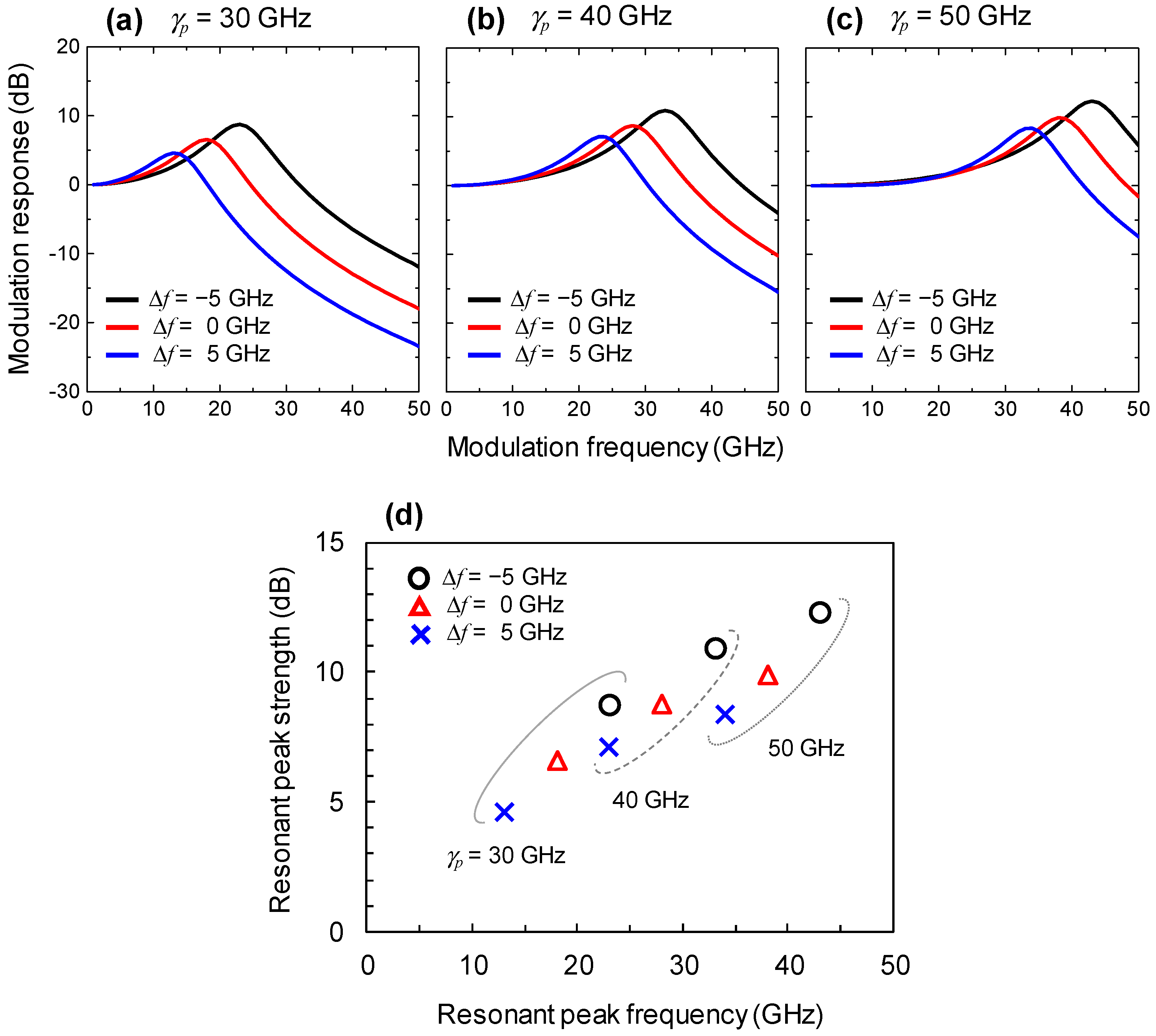
The modulation responses of an injection-locked spin-VCSEL with varying γp and ∆f are shown in Figure 4. An IR of 10 dB was used for these simulations. As shown in Figure 4a, we verified that the ∆f value affects the resonant peak frequency and resonant peak strength of the spin polarization modulation response with γp of 30 GHz. This tendency was also found with γp of 40 and 50 GHz as shown in Figure 4b,c. Figure 4d shows a summary of the resonant peak frequency and strength of the spin polarization modulation responses. The higher γp values contributed to increases in both the resonant peak frequency and strength of the modulation response. Thus, the strong birefringence in spin-VCSELs is useful for efficiently generating the orthogonally-polarized modulation sideband. The strong birefringence will be particularly desirable when data signals contain a wide bandwidth and the resulting frequency difference between the optical data signal and pilot tone (fc − ftone) requires a high frequency. The ∆f value also affected both the resonant peak frequency and the strength of the modulation response. ∆f nearly equal to zero will be the most practical and ideal situation since the locking range reaches the order of sub-gigahertz under low IRs [43]. Although high IRs are suitable for widening the locking range of the spin-VCSEL, direct use of a weak pilot tone without any optical amplifications is desirable for simplicity.
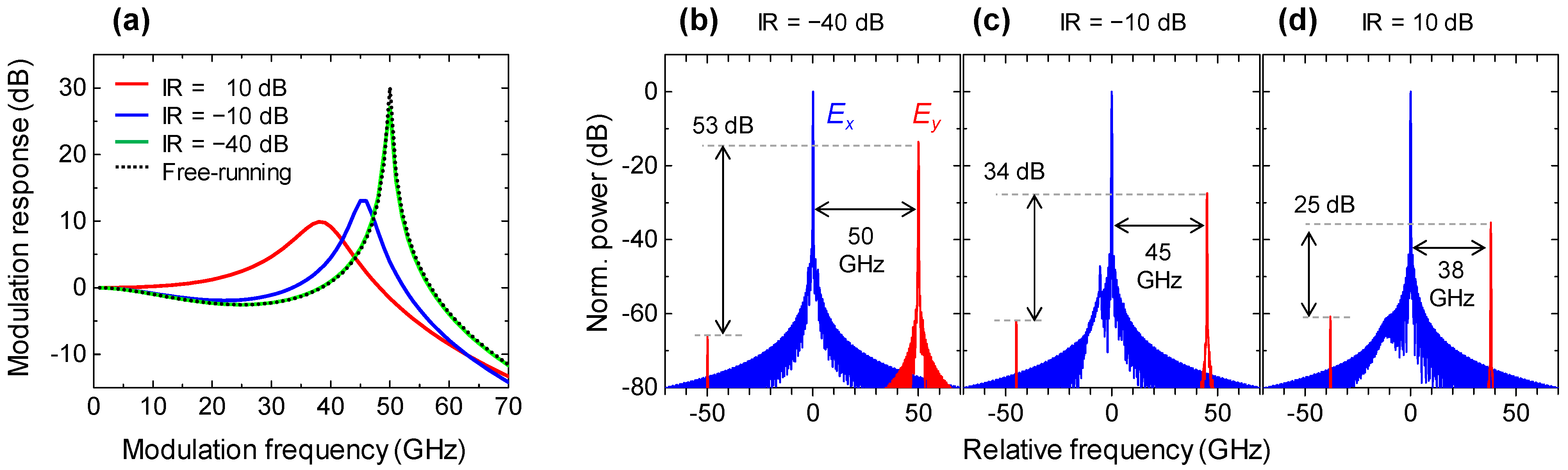
The spin polarization modulation responses of the injection-locked spin-VCSEL with different IRs are shown in Figure 5a. ∆f = 0 and γp = 50 GHz were used for these simulations. A low IR of −10 dB increased both the resonant peak frequency and the strength of the modulation response compared with when a high IR of 10 dB was used. Moreover, the response shape with a fairly low IR of −40 dB almost overlapped with that under the free-running condition. This tendency is reasonable because the free-running condition is a lower limit of the IR, and the resonant peak frequency is dominated by the γp value. Polarization-resolved optical spectra of the injection-locked spin-VCSEL with the IR of −40, −10, and 10 dB under spin polarization modulation are shown in Figure 5b–d. The fm of 50, 45, and 38 GHz are used for Figure 5b–d, respectively. The modulation sidebands have y polarization in contrast to the lasing optical carrier of x polarization. As shown in Figure 5b, the sideband intensity at 50 GHz is 53 dB stronger than that at −50 GHz, which is attributed to a relative frequency difference between the lasing polarization mode and the non-lasing residual polarization mode in a birefringent cavity. This asymmetric characteristic can imitate a single sideband modulation ideal for frequency shifting without using a narrow-band optical filter. Note that the modulation sideband includes effects of intensity modulations and chirps in the spin-VCSEL [44], which means that the sideband intensity depends on α value. The ratio between the stronger and weaker sideband intensities decreases when the IR increases as shown in Figure 5c,d. These results show that efficient generation of orthogonally-polarized single modulation sideband is feasible due to the spin polarization modulation of the injection-locked spin-VCSEL under a low IR.
3.2. Proof of Concept
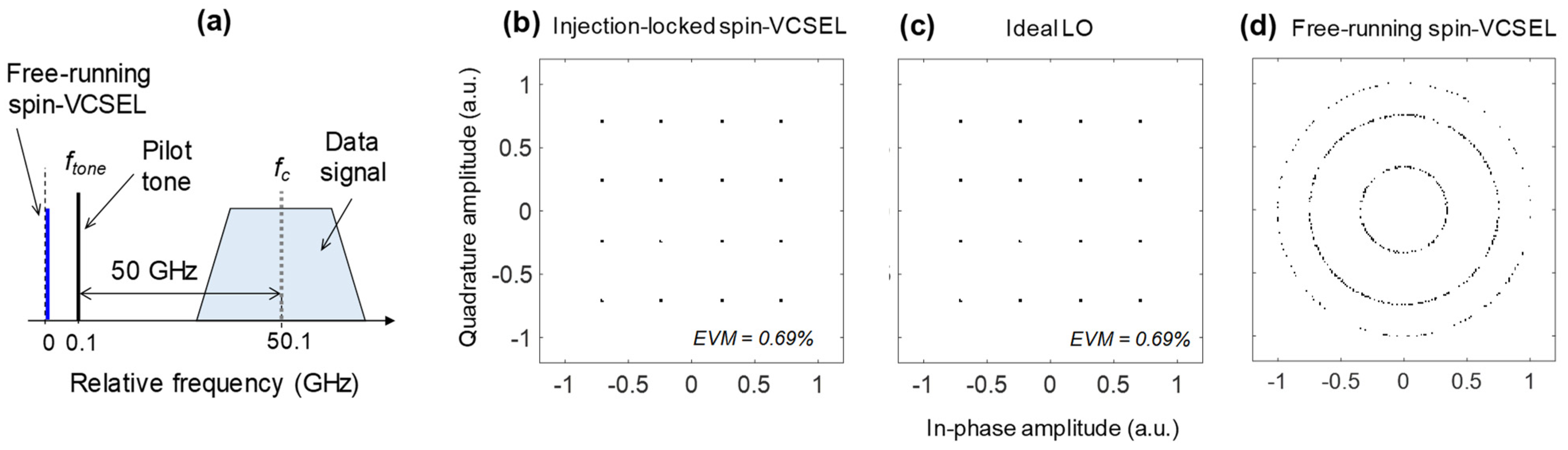
Finally, a proof-of-concept simulation was conducted using the configuration shown in Figure 3b. We used the following variable parameters: Im = 1 × Ith, fm = 50.0 GHz, γp = 50.0 GHz, fd = 24.9 GHz, ∆f = −100 MHz, fc = 50.1 GHz, and ftone = 100 MHz. The relation among fc, ftone, and data signal is schematically shown in Figure 6a. A constellation diagram of 25-Gbaud 16-QAM signals detected with the spin-VCSEL operating as a frequency-shifted LO is shown in Figure 6b. The 16-QAM signal pattern was clearly observed with a low enough EVM of 0.69%. This EVM value is dominated by nonlinear signal distortion in the DP-MZM used for the optical data signal generation. The same EVM value was also observed when the ideal LO was used (Figure 6c). These results indicate that the injection-locked spin-VCSEL can be used for the frequency-shifted LO in principle. As shown in Figure 6d, the constellation rotated when the pilot tone for the injection locking of the spin-VCSEL was removed due to the 100-MHz frequency difference between them. This result verifies that tight synchronization was obtained by the injection locking.
4. Discussion and Prospects
Although the proposed scheme was determined to be useful for obtaining LO for homodyne detection, the role of amplified spontaneous emission (ASE) noise of Er-doped fiber amplifiers which are added into optical signals should be further investigated for the proposed scheme. The ASE noise usually degrades the EVM of the detected signal when the injection-locked semiconductor laser is used as an LO [8]; this effect should be taken into account for practical application. The effect of unnecessary current modulation during the spin polarization modulation on the homodyne detected signal should also be clarified.
It is worth noting that several technical advancements are required for the proposed device function. First, the spin-VCSELs need to be integrated with silicon photonics-based components such as low-loss waveguides. Although conventional VCSELs can be fabricated on silicon [45,46,47], fabricating spin-VCSELs on silicon requires additional technologies such as electrical spin injections and transports [48,49,50,51,52,53,54]. Electrical spin injection into long wavelength active regions such as InGaAsP and InAlGaAs quantum wells is required, since the bandgap of silicon is 1.1 eV and well-studied GaAs quantum wells are not compatible. The up-spin and down-spin electron injectors may be obtained by manipulating remanence of vertically-magnetized ferromagnetic metal contacts such as Fe/Tb multilayer/Schottky [55] and FePt/MgO contacts [56] using a magnetic head similar to the case of hard disk drives. The use of spin precession of drifting electrons due to spin–orbit interactions [57] may be another approach when transversely-magnetized ferromagnetic metal contacts [25] are used in combination. Second, a polarization selective function of the device, for example, polarization extinction ratio of the lattice-shaped HCG is important for practical use. When the optical carrier remains after the polarization selective component, it causes cross talk at the stage of polarization hybrid coherent detection. Third, birefringence controls of spin-VCSELs including theoretical modeling are important for efficient generation of orthogonally-polarized modulation sideband with a high frequency [58,59,60,61,62]. Since the sensitivity of spin polarization modulation is subject to birefringence, efficient generation of an orthogonally-polarized modulation sideband requires birefringence control with accuracy in the order of a few gigahertz. Birefringence controls of spin-VCSELs on silicon will be particularly challenging since heterogeneous integration of III-V materials on silicon is usually conducted by wafer bonding techniques [47] which tend to induce non-uniform stress distribution. Electrical birefringence tuning with sub-gigahertz accuracy [63,64] is one such promising approach. Since spin-VCSELs have a possibility of improving optical signal quality [65] and high-speed modulations [28], they are expected to be used also for optical data signal generators in the coherent optical communication systems. Ideas based on electrical spin injection into silicon [66] may provide other interesting degrees of freedom to the spin-VCSEL.
5. Conclusions
We numerically investigated injection-locked spin-VCSELs for a frequency-shifted LO in coherent optical communication systems. The spin polarization modulation responses of the injection-locked spin-VCSEL indicated a resonance feature, and its peak frequency and peak strength were controlled by the injection ratio and detuning frequency. The modulation sensitivity was maximized at the lower extrema of the injection ratio corresponding to the free-running condition. The proof-of-concept simulation verified that 25-Gbaud 16-QAM signals can be homodyne detected by using the injection-locked spin-VCSEL as the frequency-shifted LO.
Author Contributions
Conceptualization, N.Y.; methodology, N.Y.; software, N.Y.; validation, N.Y. and H.Y.; formal analysis, N.Y.; investigation, N.Y.; resources, N.Y.; data curation, N.Y.; writing—original draft preparation, N.Y.; writing—review and editing, H.Y.; visualization, N.Y.; supervision, H.Y.; project administration, N.Y.; funding acquisition, N.Y. All authors have read and agreed to the published version of the manuscript.
Funding
This work was supported by The Telecommunications Advancement Foundation and JSPS KAKENHI Grant Number 19H02186.
Informed Consent Statement
Not applicable.
Data Availability Statement
The data presented in this study are available on request from the corresponding author.
Conflicts of Interest
The authors declare no conflict of interest.
References
- Ip, E.; Lau, A.P.T.; Barros, D.J.F.; Kahn, J.M. Coherent detection in optical fiber systems. Opt. Express 2008, 16, 753–791. [Google Scholar] [CrossRef] [PubMed]
- Kikuchi, K. Fundamentals of Coherent Optical Fiber Communications. J. Light. Technol. 2016, 34, 157–179. [Google Scholar] [CrossRef]
- Kikuchi, K. Phase-diversity homodyne detection of multilevel optical modulation with digital carrier phase estimation. IEEE J. Sel. Top. Quantum Electron. 2006, 12, 563–570. [Google Scholar] [CrossRef]
- Pfau, T.; Hoffmann, S.; Noe, R. Hardware-Efficient Coherent Digital Receiver Concept with Feedforward Carrier Recovery for M-QAM Constellations. J. Light. Technol. 2009, 27, 989–999. [Google Scholar] [CrossRef]
- Fatadin, I.; Ives, D.; Savory, S.J. Laser Linewidth Tolerance for 16-QAM Coherent Optical Systems Using QPSK Partitioning. IEEE Photon. Technol. Lett. 2010, 22, 631–633. [Google Scholar] [CrossRef]
- Kasai, K.; Hongo, J.; Yoshida, M.; Nakazawa, M. Optical phase-locked loop for coherent transmission over 500km using heterodyne detection with fiber lasers. IEICE Electron. Express 2007, 4, 77–81. [Google Scholar] [CrossRef] [Green Version]
- Balakier, K.; Ponnampalam, L.; Fice, M.J.; Renaud, C.C.; Seeds, A.J. Integrated Semiconductor Laser Optical Phase Lock Loops. IEEE J. Sel. Top. Quantum Electron. 2018, 24, 1500112. [Google Scholar] [CrossRef] [Green Version]
- Fice, M.J.; Chiuchiarelli, A.; Ciaramella, E.; Seeds, A.J. Homodyne Coherent Optical Receiver Using an Optical Injection Phase-Lock Loop. J. Light. Technol. 2011, 29, 1152–1164. [Google Scholar] [CrossRef]
- Liu, Z.; Kim, J.; Wu, D.S.; Richardson, D.J.; Slavík, R. Homodyne OFDM with Optical Injection Locking for Carrier Recovery. J. Light. Technol. 2015, 33, 34–41. [Google Scholar] [CrossRef] [Green Version]
- Kasai, K.; Wang, Y.; Beppu, S.; Yoshida, M.; Nakazawa, M. 80 Gbit/s, 256 QAM coherent transmission over 150 km with an injection-locked homodyne receiver. Opt. Express 2015, 23, 29174–29183. [Google Scholar] [CrossRef]
- Kasai, K.; Hirooka, T.; Yoshida, M.; Nakazawa, M. 64 Gbit/s, 256 QAM Coherently-Linked Optical and Wireless Transmission in 61 GHz Band Using Novel Injection-Locked Carrier Frequency Converter. In Proceedings of the 2020 European Conference on Optical Communications (ECOC), Brussels, Belgium, 6–10 December 2020; pp. 1–3. [Google Scholar]
- Radziunas, M.; Glitzky, A.; Bandelow, U.; Wolfrum, M.; Troppenz, U.; Kreissl, J.; Rehbein, W. Improving the Modulation Bandwidth in Semiconductor Lasers by Passive Feedback. IEEE J. Sel. Top. Quantum Electron. 2007, 13, 136–142. [Google Scholar] [CrossRef]
- Bardella, P.; Montrosset, I. A New Design Procedure for DBR Lasers Exploiting the Photon-Photon Resonance to Achieve Extended Modulation Bandwidth. IEEE J. Sel. Top. Quantum Electron. 2013, 19, 1502408. [Google Scholar] [CrossRef]
- Mieda, S.; Yokota, N.; Kobayashi, W.; Yasaka, H. Ultra-Wide-Bandwidth Optically Controlled DFB Laser With External Cavity. IEEE J. Quantum Electron. 2016, 52, 2200107. [Google Scholar] [CrossRef]
- Hong, B.; Kitano, T.; Mori, T.; Jiang, H.; Hamamoto, K. Bandwidth enhancement scheme demonstration on direct modulation active-MMI laser diode using multiple photon photon resonance. Appl. Phys. Lett. 2017, 111, 221105. [Google Scholar] [CrossRef]
- Hallstein, S.; Berger, J.D.; Hilpert, M.; Schneider, H.C.; Rühle, W.W.; Jahnke, F.; Koch, S.W.; Gibbs, H.M.; Khitrova, G.; Oestreich, M. Manifestation of coherent spin precession in stimulated semiconductor emission dynamics. Phys. Rev. B 1997, 56, R7076–R7079. [Google Scholar] [CrossRef]
- Ando, H.; Sogawa, T.; Gotoh, T. Photon-spin controlled lasing oscillation in surface-emitting lasers. Appl. Phys. Lett. 1998, 73, 566–568. [Google Scholar] [CrossRef]
- Holub, M.; Shin, J.; Saha, D.; Bhattacharya, P. Electrical Spin Injection and Threshold Reduction in a Semiconductor Laser. Phys. Rev. Lett. 2007, 98, 146603. [Google Scholar] [CrossRef]
- Holub, M.; Bhattacharya, P. Spin-polarized light-emitting diodes and lasers. J. Phys. D Appl. Phys. 2007, 40, R179–R203. [Google Scholar] [CrossRef]
- Basu, D.; Saha, D.; Wu, C.C.; Holub, M.; Mi, Z.; Bhattacharya, P. Electrically injected InAs/GaAs quantum dot spin laser operating at 200K. Appl. Phys. Lett. 2008, 92, 091119. [Google Scholar] [CrossRef]
- Iba, S.; Koh, S.; Ikeda, K.; Kawaguchi, H. Room temperature circularly polarized lasing in an optically spin injected vertical-cavity surface-emitting laser with (110) GaAs quantum wells. Appl. Phys. Lett. 2011, 98, 081113. [Google Scholar] [CrossRef]
- Žutić, I.; Xu, G.; Lindemann, M.; Faria Junior, P.E.; Lee, J.; Labinac, V.; Stojšić, K.; Sipahi, G.M.; Hofmann, M.R.; Gerhardt, N.C. Spin-lasers: Spintronics beyond magnetoresistance. Solid State Commun. 2020, 316–317, 113949. [Google Scholar] [CrossRef]
- Xu, G.; Cao, J.D.; Labinac, V.; Žutić, I. Intensity equations for birefringent spin lasers. Phys. Rev. B 2021, 103, 045306. [Google Scholar] [CrossRef]
- Sinova, J.; Žutić, I. New moves of the spintronics tango. Nat. Mater. 2012, 11, 368–371. [Google Scholar] [CrossRef]
- Nishizawa, N.; Aoyama, M.; Roca, R.C.; Nishibayashi, K.; Munekata, H. Arbitrary helicity control of circularly polarized light from lateral-type spin-polarized light-emitting diodes at room temperature. Appl. Phys. Express 2018, 11, 053003. [Google Scholar] [CrossRef] [Green Version]
- Gerhardt, N.C.; Li, M.Y.; Jähme, H.; Höpfner, H.; Ackemann, T.; Hofmann, M.R. Ultrafast spin-induced polarization oscillations with tunable lifetime in vertical-cavity surface-emitting lasers. Appl. Phys. Lett. 2011, 99, 151107. [Google Scholar] [CrossRef]
- Torre, M.S.; Susanto, H.; Nianqiang, L.; Schires, K.; Salvide, M.F.; Henning, I.D.; Adams, M.J.; Hurtado, A. High frequency continuous birefringence-induced oscillations in spin-polarized vertical-cavity surface-emitting lasers. Opt. Lett. 2017, 42, 1628–1631. [Google Scholar] [CrossRef] [PubMed] [Green Version]
- Lindemann, M.; Xu, G.; Pusch, T.; Michalzik, R.; Hofmann, M.R.; Žutić, I.; Gerhardt, N.C. Ultrafast spin-lasers. Nature 2019, 568, 212–215. [Google Scholar] [CrossRef] [PubMed]
- Yokota, N.; Nisaka, K.; Yasaka, H.; Ikeda, K. Spin polarization modulation for high-speed vertical-cavity surface-emitting lasers. Appl. Phys. Lett. 2018, 113, 171102. [Google Scholar] [CrossRef]
- Zhou, Y.; Huang, M.C.; Chase, C.; Karagodsky, V.; Moewe, M.; Pesala, B.; Sedgwick, F.G.; Chang-Hasnain, C.J. High-Index-Contrast Grating (HCG) and Its Applications in Optoelectronic Devices. IEEE J. Sel. Top. Quantum Electron. 2009, 15, 1485–1499. [Google Scholar] [CrossRef]
- Katayama, T.; Ito, J.; Kawaguchi, H. Polarization-dependent coupling between a polarization-independent high-index-contrast subwavelength grating and waveguides. Appl. Phys. Express 2016, 9, 072703. [Google Scholar] [CrossRef]
- Miguel, M.S.; Feng, Q.; Moloney, J.V. Light-polarization dynamics in surface-emitting semiconductor lasers. Phys. Rev. A 1995, 52, 1728–1739. [Google Scholar] [CrossRef] [PubMed]
- Li, N.; Susanto, H.; Cemlyn, B.; Henning, I.D.; Adams, M.J. Secure communication systems based on chaos in optically pumped spin-VCSELs. Opt. Lett. 2017, 42, 3494–3497. [Google Scholar] [CrossRef]
- Cemlyn, B.R.; Henning, I.D.; Adams, M.J.; Harbord, E.; Oulton, R.; Korpijärvi, V.-M.; Guina, M. Polarization Responses of a Solitary and Optically Injected Vertical Cavity Spin Laser. IEEE J. Quantum Electron. 2019, 55, 2400409. [Google Scholar] [CrossRef] [Green Version]
- Krishna, K.M.; Madhan, M.G.; Ashok, P. Simulation studies on polarization modulated vertical cavity surface emitting laser for combined fiber and free space optical links. Optik 2020, 219, 165018. [Google Scholar] [CrossRef]
- Song, T.; Xie, Y.; Ye, Y.; Liu, B.; Chai, J.; Jiang, X.; Zheng, Y. Numerical Analysis of Nonlinear Dynamics Based on Spin-VCSELs with Optical Feedback. Photonics 2021, 8, 10. [Google Scholar] [CrossRef]
- Yokota, N.; Ikeda, K.; Yasaka, H. Spin-Injected Birefringent VCSELs for Analog Radio-Over-Fiber Systems. IEEE Photon. Technol. Lett. 2021, 33, 297–300. [Google Scholar] [CrossRef]
- Zhong, D.; Zeng, N.; Yang, H.; Xu, Z.; Hu, Y.; Zhao, K. Precise ranging for the multi-region by using multi-beam chaotic polarization components in the multiple parallel optically pumped spin-VCSELs with optical injection. Opt. Express 2021, 29, 7809–7824. [Google Scholar] [CrossRef] [PubMed]
- Park, M.-R.; Kwon, O.-K.; Han, W.-S.; Lee, K.-H.; Park, S.-J.; Yoo, B.-S. All-epitaxial InAlGaAs-InP VCSELs in the 1.3-1.6-μm wavelength range for CWDM band applications. IEEE Photon. Technol. Lett. 2006, 18, 1717–1719. [Google Scholar] [CrossRef]
- Pérez, P.; Valle, A.; Noriega, I.; Pesquera, L. Measurement of the Intrinsic Parameters of Single-Mode VCSELs. J. Light. Technol. 2014, 32, 1601–1607. [Google Scholar] [CrossRef] [Green Version]
- Yokota, N.; Ikeda, K.; Yasaka, H. Numerical investigation of direct IQ modulation of spin-VCSELs for coherent communications. Proc. SPIE 2020, 11470, 114702I. [Google Scholar]
- Yokota, N.; Yasaka, H. Cascaded SSB comb generation using injection-locked seed lasers. Opt. Lett. 2021, 46, 769–772. [Google Scholar] [CrossRef] [PubMed]
- Liu, Z.; Slavík, R. Optical Injection Locking: From Principle to Applications. J. Light. Technol. 2020, 38, 43–59. [Google Scholar] [CrossRef]
- Boéris, G.; Lee, J.; Výborný, K.; Žutić, I. Tailoring chirp in spin-lasers. Appl. Phys. Lett. 2012, 100, 121111. [Google Scholar] [CrossRef] [Green Version]
- Chung, I.S.; Mørk, J. Silicon-photonics light source realized by III–V/Si-grating-mirror laser. Appl. Phys. Lett. 2010, 97, 151113. [Google Scholar] [CrossRef] [Green Version]
- Tsunemi, Y.; Yokota, N.; Majima, S.; Ikeda, K.; Katayama, T.; Kawaguchi, H. 1.55-μm VCSEL with polarization-independent HCG mirror on SOI. Opt. Express 2013, 21, 28685–28692. [Google Scholar] [CrossRef]
- Ferrara, J.; Yang, W.; Zhu, L.; Qiao, P.; Chang-Hasnain, C.J. Heterogeneously integrated long-wavelength VCSEL using silicon high contrast grating on an SOI substrate. Opt. Express 2015, 23, 2512–2523. [Google Scholar] [CrossRef]
- Oestreich, M.; Hübner, J.; Hägele, D.; Klar, P.J.; Heimbrodt, W.; Rühle, W.W.; Ashenford, D.E.; Lunn, B. Spin injection into semiconductors. Appl. Phys. Lett. 1999, 74, 1251. [Google Scholar] [CrossRef]
- Young, D.K.; Johnston-Halperin, E.; Awschalom, D.D.; Ohno, Y.; Ohno, H. Anisotropic electrical spin injection in ferromagnetic semiconductor heterostructures. Appl. Phys. Lett. 2002, 80, 1598. [Google Scholar] [CrossRef] [Green Version]
- Hanbicki, A.T.; Jonker, B.T.; Itskos, G.; Kioseoglou, G.; Petrou, A. Efficient electrical spin injection from a metal/tunnel barrier contact into a semiconductor. Appl. Phys. Lett. 2002, 80, 1240. [Google Scholar] [CrossRef]
- Yokota, N.; Aoshima, Y.; Ikeda, K.; Nishizawa, N.; Munekata, H.; Kawaguchi, H. Room temperature spin injection into (110) GaAs quantum wells using Fe/x-AlOx contacts in the regime of current density comparable to laser oscillation. J. Appl. Phys. 2015, 118, 163905. [Google Scholar] [CrossRef]
- Nishizawa, N.; Nishibayashi, K.; Munekata, H. Pure circular polarization electroluminescence at room temperature with spin-polarized light-emitting diodes. Proc. Natl Acad. Sci. USA 2017, 114, 1783–1788. [Google Scholar] [CrossRef] [Green Version]
- Yokota, N.; Aoshima, Y.; Ikeda, K.; Kawaguchi, H. Room temperature spin transport in undoped (110) GaAs/AlGaAs quantum wells. Appl. Phys. Lett. 2014, 104, 072406. [Google Scholar] [CrossRef]
- Ohno, Y.; Iba, S.; Okamoto, R.; Obata, Y.; Obu, K.; Domingez, J.J.P.; Saito, H. Room-temperature spin relaxation in a (110)-oriented GaAs/AlGaAs superlattice with tunnel-coupled quantum wells. Appl. Phys. Express 2020, 13, 123003. [Google Scholar] [CrossRef]
- Gerhardt, N.C.; Hövel, S.; Brenner, C.; Hofmann, M.R.; Lo, F.-Y.; Reuter, D.; Wieck, A.D.; Schuster, E.; Keune, W.; Halm, S.; et al. Spin injection light-emitting diode with vertically magnetized ferromagnetic metal contacts. J. Appl. Phys. 2006, 99, 073907. [Google Scholar] [CrossRef]
- Sinsarp, A.; Manago, T.; Takano, F.; Akinaga, H. Electrical Spin Injection from Out-of-Plane Magnetized FePt/MgO Tunneling Junction into GaAs at Room Temperature. Jpn. J. Appl. Phys. 2007, 46, L4–L6. [Google Scholar] [CrossRef]
- Kunihashi, Y.; Sanada, H.; Gotoh, H.; Onomitsu, K.; Kohda, M.; Nitta, J.; Sogawa, T. Drift transport of helical spin coherence with tailored spin–orbit interactions. Nat. Commun. 2016, 7, 10722. [Google Scholar] [CrossRef] [Green Version]
- Lindemann, M.; Pusch, T.; Michalzik, R.; Gerhardt, N.C.; Hofmann, M.R. Frequency tuning of polarization oscillations: Toward high-speed spin-lasers. Appl. Phys. Lett. 2016, 108, 042404. [Google Scholar] [CrossRef]
- Yokota, N.; Takeuchi, R.; Yasaka, H.; Ikeda, K. Lasing Polarization Characteristics in 1.55-μm Spin-Injected VCSELs. IEEE Photon. Technol. Lett. 2017, 29, 711–714. [Google Scholar] [CrossRef]
- Pusch, T.; Debernardi, P.; Lindemann, M.; Erb, F.; Gerhardt, N.C.; Hofmann, M.R.; Michalzik, R. Vertical-cavity surface-emitting laser with integrated surface grating for high birefringence splitting. Electron. Lett. 2019, 55, 1055–1057. [Google Scholar] [CrossRef]
- Alouini, M.; Frougier, J.; Joly, A.; Baili, G.; Dolfi, D.; George, J.-M. VSPIN: A new model relying on the vectorial description of the laser field for predicting the polarization dynamics of spin-injected V(e)CSELs. Opt. Express 2018, 26, 6739–6757. [Google Scholar] [CrossRef]
- Drong, M.; Fördös, T.; Jaffrès, H.Y.; Peřina, J., Jr.; Postava, K.; Ciompa, P.; Pištora, J.; Drouhin, H.-J. Spin-VCSELs with Local Optical Anisotropies: Toward Terahertz Polarization Modulation. Phys. Rev. Appl. 2021, 15, 014041. [Google Scholar] [CrossRef]
- Pusch, T.; La Tona, E.; Lindemann, M.; Gerhardt, N.C.; Hofmann, M.R.; Michalzik, R. Monolithic vertical-cavity surface-emitting laser with thermally tunable birefringence. Appl. Phys. Lett. 2017, 110, 151106. [Google Scholar] [CrossRef]
- Lindemann, M.; Jung, N.; Stadler, P.; Pusch, T.; Michalzik, R.; Hofmann, M.R.; Gerhardt, N.C. Bias current and temperature dependence of polarization dynamics in spin-lasers with electrically tunable birefringence. AIP Adv. 2020, 10, 035211. [Google Scholar] [CrossRef]
- Wasner, E.; Bearden, S.; Lee, J.; Žutić, I. Digital operation and eye diagrams in spin-lasers. Appl. Phys. Lett. 2015, 107, 082406. [Google Scholar] [CrossRef]
- Žutić, I.; Fabian, J.; Erwin, S.C. Spin Injection and Detection in Silicon. Phys. Rev. Lett. 2006, 97, 026602. [Google Scholar] [CrossRef] [PubMed] [Green Version]
Figure 1.
Schematic of coherent optical communication system based on frequency-shifted LO.

Figure 2.
(a) Schematic of frequency-shifted LO based on injection-locked spin-VCSEL; (b) Example device structure of frequency-shifted LO with integrated configuration.
Figure 2.
(a) Schematic of frequency-shifted LO based on injection-locked spin-VCSEL; (b) Example device structure of frequency-shifted LO with integrated configuration.

Figure 3.
(a) Schematic of detuning condition for injection locking; (b) Schematic of proof-of-concept simulation of frequency-shifted LO based on injection-locked spin-VCSEL for homodyne detection.
Figure 3.
(a) Schematic of detuning condition for injection locking; (b) Schematic of proof-of-concept simulation of frequency-shifted LO based on injection-locked spin-VCSEL for homodyne detection.

Figure 4.
Spin polarization modulation responses of injection-locked spin-VCSELs calculated with IR of 10 dB. (a) γp = 30 GHz; (b) γp = 40 GHz; (c) γp = 50 GHz. Black, red, and blue curves indicate results for ∆f of −5, 0, and 5 GHz, respectively. (d) Resonant peak strengths in relation to resonant peak frequencies observed in spin polarization modulation responses. Values for ∆f of −5, 0, and 5 GHz are indicated by the circles, triangles, and crosses, respectively. Values for γp of 30, 40, and 50 GHz are grouped by solid, dashed, and dotted curves, respectively.

Figure 5.
(a) Spin polarization modulation response under injection locking condition with different IRs and under free-running condition; Polarization-resolved optical spectra under spin polarization modulation of injection-locked spin-VCSEL. (b) IR = −40 dB, fm = 50 GHz; (c) IR = −10 dB, fm = 45 GHz; (d) IR = 10 dB, fm = 38 GHz. Blue and red curves indicate x and y polarization components, respectively. These are calculated with ∆f of 0 and γp of 50 GHz.

Figure 6.
(a) Schematic relation among fc, ftone, and data signal. Constellation diagrams of detected 25-Gbaud 16-QAM signals. (b) With injection-locked spin-VCSEL; (c) With ideal LO; (d) With free-running spin-VCSEL.
Figure 6.
(a) Schematic relation among fc, ftone, and data signal. Constellation diagrams of detected 25-Gbaud 16-QAM signals. (b) With injection-locked spin-VCSEL; (c) With ideal LO; (d) With free-running spin-VCSEL.


Table 1.
Simulation parameters. Ith denotes threshold current.
| Symbol | Meaning | Value |
|---|---|---|
| I0 | Static current | 2 Ith |
| Im | Current modulation coefficient | 0.1 × Ith or 1 × Ith |
| fm | Modulation frequency | Variable |
| V | Cavity volume | 2.5 × 10⁻¹⁸ m3 |
| vg | Group velocity | 9.3 × 10⁷ m/s |
| Ag | Differential gain coefficient | 1.2 × 10⁻²⁰ m2 |
| Nt | Transparency carrier density | 3.8 × 1024 m−3 |
| ε | Gain compression factor | 1.0 × 10⁻²⁴ m3 |
| τc | Carrier lifetime | 1.2 ns |
| τs | Electron spin relaxation time | 20 ps |
| τp | Photon lifetime | 19 ps |
| α | Linewidth enhancement factor | 2.8 |
| Γ | Confinement factor | 0.05 |
| γa | Dichroism | 0.5 GHz |
| γp | Linear birefringence | Variable |
| fd | Detuning frequency | Variable |
| κ | Coupling rate | 1.2 × 10¹¹ s−1 |
Publisher’s Note: MDPI stays neutral with regard to jurisdictional claims in published maps and institutional affiliations. |
© 2021 by the authors. Licensee MDPI, Basel, Switzerland. This article is an open access article distributed under the terms and conditions of the Creative Commons Attribution (CC BY) license (https://creativecommons.org/licenses/by/4.0/).
Share and Cite
MDPI and ACS Style
Yokota, N.; Yasaka, H. Spin Laser Local Oscillators for Homodyne Detection in Coherent Optical Communications. Micromachines 2021, 12, 573. https://0-doi-org.brum.beds.ac.uk/10.3390/mi12050573
AMA Style
Yokota N, Yasaka H. Spin Laser Local Oscillators for Homodyne Detection in Coherent Optical Communications. Micromachines. 2021; 12(5):573. https://0-doi-org.brum.beds.ac.uk/10.3390/mi12050573
Chicago/Turabian StyleYokota, Nobuhide, and Hiroshi Yasaka. 2021. "Spin Laser Local Oscillators for Homodyne Detection in Coherent Optical Communications" Micromachines 12, no. 5: 573. https://0-doi-org.brum.beds.ac.uk/10.3390/mi12050573
Note that from the first issue of 2016, this journal uses article numbers instead of page numbers. See further details here.