
3D-Printed Micro-Tweezers with a Compliant Mechanism Designed Using Topology Optimization

 , , , , and
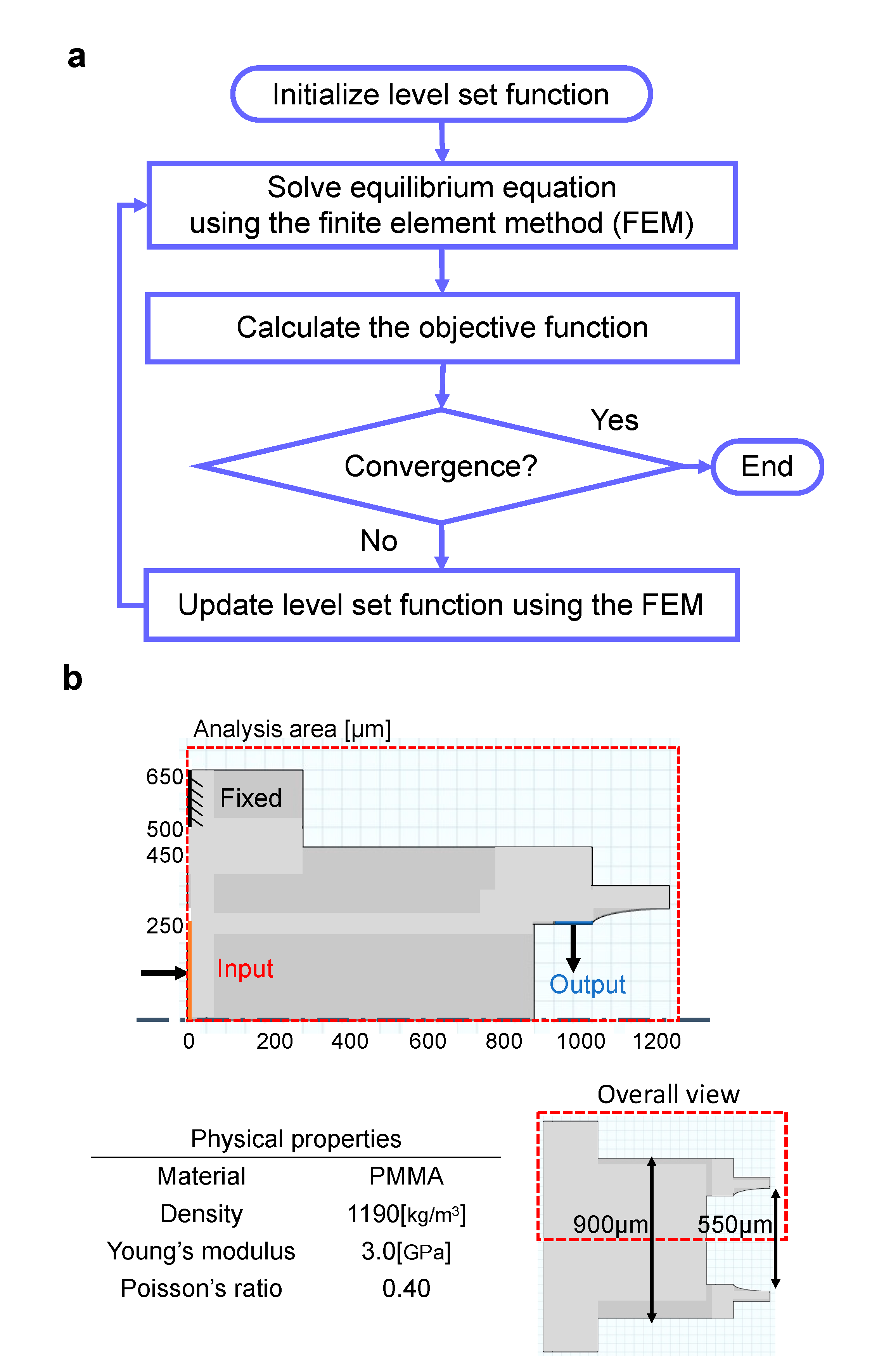
Abstract
:1. Introduction
2. Materials and Methods
2.1. Topology Optimization of Micro-Tweezers with a Compliant Mechanism
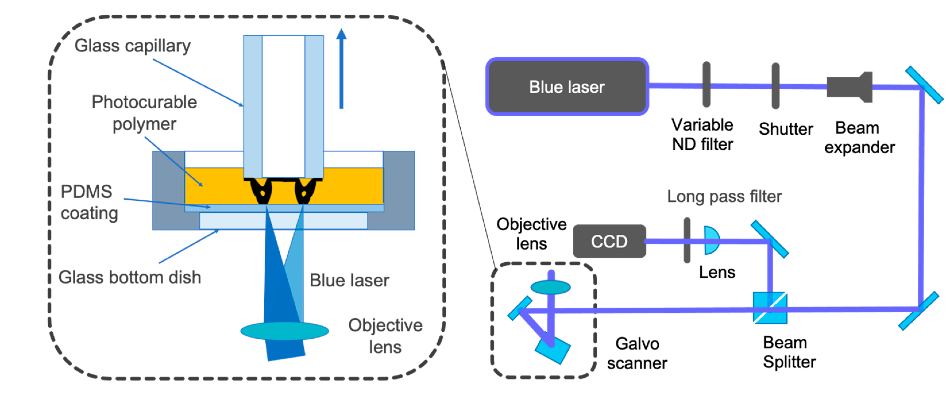
2.2. Microstereolithography System Using a 405-nm Blue Laser
2.3. Preparation of the Photocurable Polymer
2.4. Preparation of a Glass-Bottom Dish and Glass Capillary
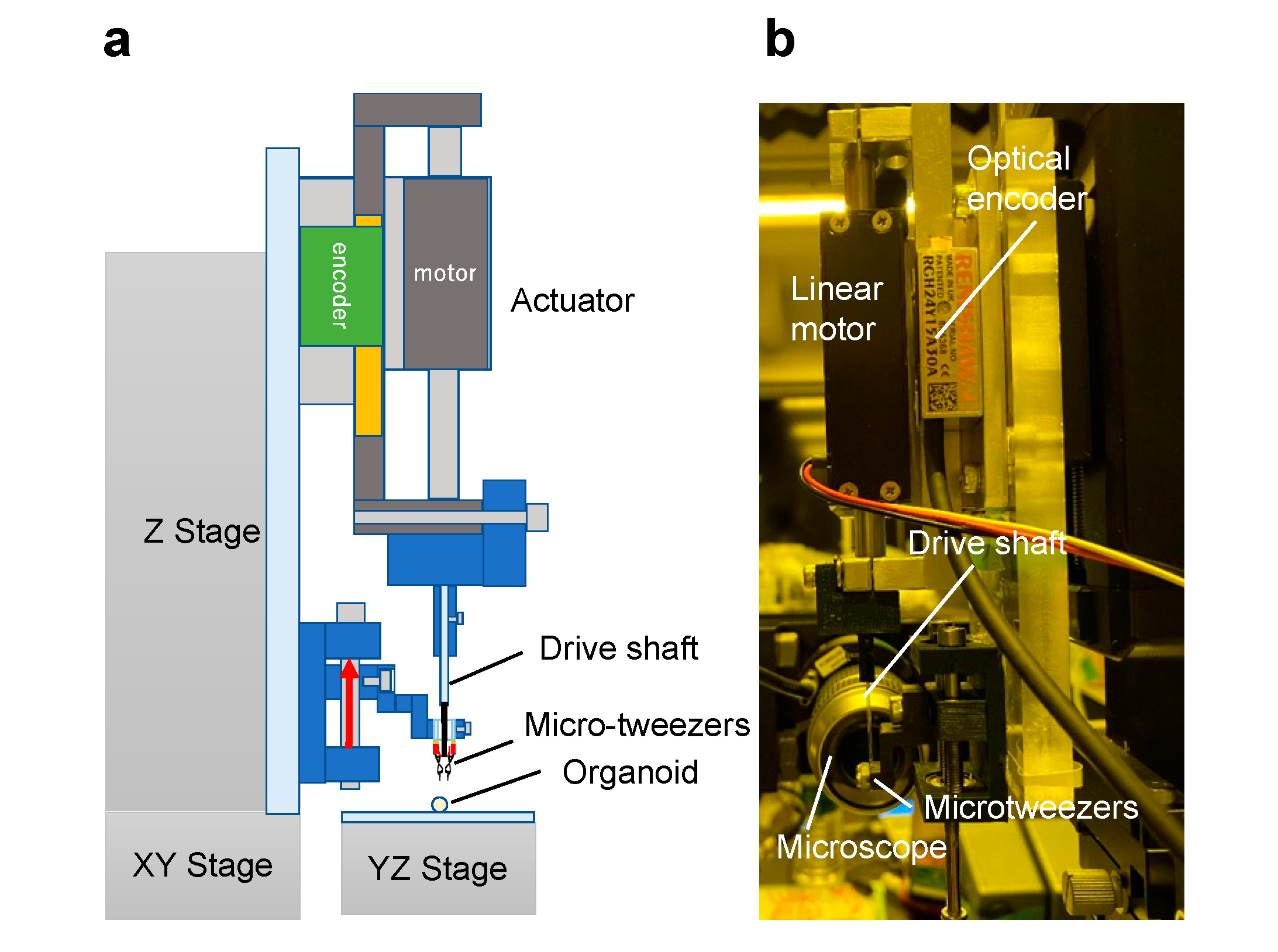
2.5. Actuation System for Micro-Tweezers
2.6. Preparation of Organoids
3. Results and Discussion
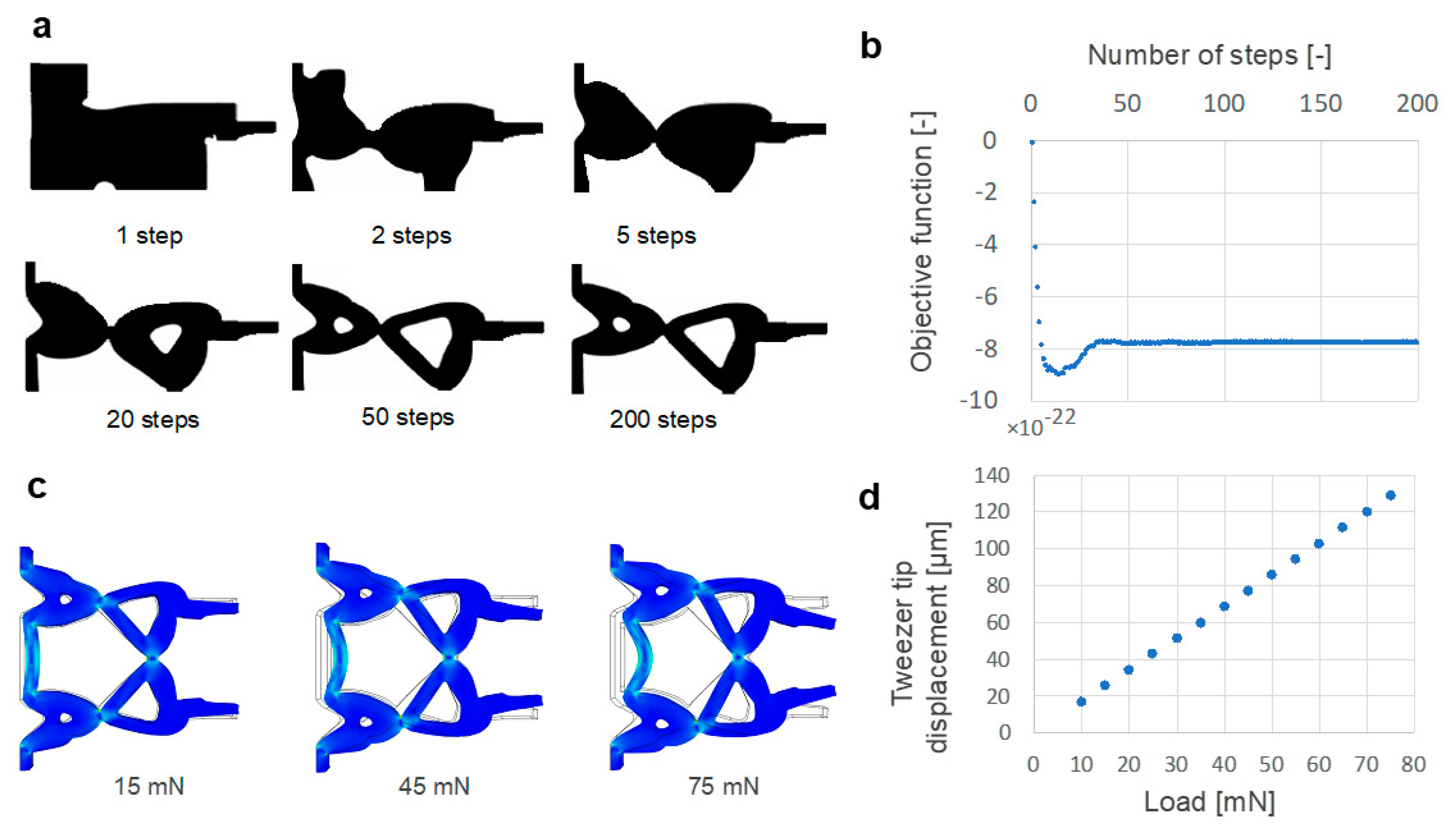
3.1. Topology Optimization Results and Simulation of the Motion of Micro-Tweezers
3.2. Fabrication of Micro-Tweezers for Manipulating an Organoid
3.3. Manipulation of an Organoid Using the Topology-Optimized Micro-Tweezers
4. Conclusions
Author Contributions
Funding
Conflicts of Interest
References
- Desai, J.P.; Pillarisetti, A.; Brooks, A.D. Engineering approaches to biomanipulation. Annu. Rev. Biomed. Eng. 2007, 9, 35–53. [Google Scholar] [CrossRef] [PubMed] [Green Version]
- Collard, D.; Takeuchi, S.; Fujita, H. MEMS technology for nanobio research. Drug Discov. Today 2008, 13, 989–996. [Google Scholar] [CrossRef] [PubMed]
- Fukuda, T.; Arai, F.; Nakajima, M. Micro-Nanorobotic Manipulation Systems and Their Applications; Springer Science & Business Media: Berlin/Heidelberg, Germany, 2013. [Google Scholar]
- Zhang, Z.R.; Wang, X.; Liu, J.; Dai, C.S.; Sun, Y. Robotic Micromanipulation: Fundamentals and applications. Annu. Rev. Control Robot. Auton. Syst. 2019, 2, 181–203. [Google Scholar] [CrossRef]
- Tanikawa, T.; Arai, T. Development of a micro-manipulation system having a two-fingered micro-hand. IEEE Trans. Robot. Autom. 1999, 15, 152–162. [Google Scholar] [CrossRef]
- Hashiguchi, G.; Goda, T.; Hosogi, M.; Hirano, K.; Kaji, N.; Baba, Y.; Kakushima, K.; Fujita, H. DNA manipulation and retrieval from an aqueous solution with micromachined nanotweezers. Anal. Chem. 2003, 75, 4347–4350. [Google Scholar] [CrossRef] [PubMed]
- Volland, B.E.; Heerlein, H.; Rangelow, I.W. Electrostatically driven microgripper. Microelectron. Eng. 2002, 61–62, 1015–1023. [Google Scholar] [CrossRef]
- Hagiwara, M.; Kawahara, T.; Yamanishi, Y.; Masuda, T.; Feng, L.; Arai, F. On-chip magnetically actuated robot with ultrasonic vibration for single cell manipulations. Lab Chip 2011, 11, 2049–2054. [Google Scholar] [CrossRef]
- Kim, P.; Lieber, C.M. Nanotube nanotweezers. Science 1999, 286, 2148–2150. [Google Scholar] [CrossRef]
- Grier, D.G. A revolution in optical manipulation. Nature 2003, 424, 810–816. [Google Scholar] [CrossRef]
- Ding, X.Y.; Lin, S.C.S.; Kiraly, B.; Yue, H.J.; Li, S.X.; Chiang, I.K.; Shi, J.J.; Benkovic, S.J.; Huang, T.J. On-chip manipulation of single microparticles, cells, and organisms using surface acoustic waves. Proc. Natl. Acad. Sci. USA 2012, 109, 11105–11109. [Google Scholar] [CrossRef] [Green Version]
- Gosse, C.; Croquette, V. Magnetic tweezers: Micromanipulation and force measurement at the molecular level. Biophys. J. 2002, 82, 3314–3329. [Google Scholar] [CrossRef] [Green Version]
- Fan, D.L.; Zhu, F.Q.; Cammarata, R.C.; Chien, C.L. Electric tweezers. Nano Today 2011, 6, 339–354. [Google Scholar] [CrossRef]
- Desmaele, D.; Boukallel, M.; Regnier, S. Actuation means for the mechanical stimulation of living cells via microelectromechanical systems: A critical review. J. Biomech. 2011, 44, 1433–1446. [Google Scholar] [CrossRef] [Green Version]
- Almeida, A.; Andrews, G.; Jaiswal, D.; Hoshino, K. The actuation mechanism of 3D printed flexure-based robotic microtweezers. Micromachines 2019, 10, 470. [Google Scholar] [CrossRef] [PubMed] [Green Version]
- Zhu, B.L.; Zhang, X.M.; Zhang, H.C.; Liang, J.W.; Zang, H.Y.; Li, H.; Wang, R.X. Design of compliant mechanisms using continuum topology optimization: A review. Mech. Mach. Theory 2020, 143, 103622. [Google Scholar] [CrossRef]
- Kozaki, S.; Moritoki, Y.; Furukawa, T.; Akieda, H.; Kageyama, T.; Fukuda, J.; Maruo, S. Additive manufacturing of micromanipulator mounted on a glass capillary for biological applications. Micromachines 2020, 11, 174. [Google Scholar] [CrossRef] [Green Version]
- Yamada, T.; Izui, K.; Nishiwaki, S.; Takezawa, A. A topology optimization method based on the level set method incorporating a fictitious interface energy. Comput. Methods Appl. Mech. Eng. 2010, 199, 2876–2891. [Google Scholar] [CrossRef] [Green Version]
- Maruo, S.; Nakamura, O.; Kawata, S. Three-dimensional microfabrication with two-photon-absorbed photopolymerization. Opt. Lett. 1997, 22, 132–134. [Google Scholar] [CrossRef] [PubMed] [Green Version]
- Dendukuri, D.; Pregibon, D.C.; Collins, J.; Hatton, T.A.; Doyle, P.S. Continuous-flow lithography for high-throughput microparticle synthesis. Nat. Mater. 2006, 5, 365–369. [Google Scholar] [CrossRef]
- Murakami, T.; Yu, F.M.; Ohnishi, K. Torque sensorless control in multidegree-of-freedom manipulator. IEEE Trans. Ind. Electron. 1993, 40, 259–265. [Google Scholar] [CrossRef]
- Yokoyama, M.; Shimono, T.; Yamashita, C.; Nagasaka, S.; Ohara, T. Reduction of contact force fluctuation for rotary wear test apparatus. IEEE/ASME Trans. Mechatron. 2019, 25, 185–194. [Google Scholar] [CrossRef]
- Kageyama, T.; Yoshimura, C.; Myasnikova, D.; Kataoka, K.; Nittami, T.; Maruo, S.; Fukuda, J. Spontaneous hair follicle germ (HFG) formation in vitro, enabling the large-scale production of HFGs for regenerative medicine. Biomaterials 2018, 154, 291–300. [Google Scholar] [CrossRef] [PubMed]
- Maruyama, T.; Hirata, H.; Furukawa, T.; Maruo, S. Multi-material microstereolithography using a palette with multicolor photocurable resins. Opt. Mater. Express 2020, 10, 2522–2532. [Google Scholar] [CrossRef]


Publisher’s Note: MDPI stays neutral with regard to jurisdictional claims in published maps and institutional affiliations. |
© 2021 by the authors. Licensee MDPI, Basel, Switzerland. This article is an open access article distributed under the terms and conditions of the Creative Commons Attribution (CC BY) license (https://creativecommons.org/licenses/by/4.0/).
Share and Cite
Moritoki, Y.; Furukawa, T.; Sun, J.; Yokoyama, M.; Shimono, T.; Yamada, T.; Nishiwaki, S.; Kageyama, T.; Fukuda, J.; Mukai, M.; et al. 3D-Printed Micro-Tweezers with a Compliant Mechanism Designed Using Topology Optimization. Micromachines 2021, 12, 579. https://0-doi-org.brum.beds.ac.uk/10.3390/mi12050579
Moritoki Y, Furukawa T, Sun J, Yokoyama M, Shimono T, Yamada T, Nishiwaki S, Kageyama T, Fukuda J, Mukai M, et al. 3D-Printed Micro-Tweezers with a Compliant Mechanism Designed Using Topology Optimization. Micromachines. 2021; 12(5):579. https://0-doi-org.brum.beds.ac.uk/10.3390/mi12050579
Chicago/Turabian StyleMoritoki, Yukihito, Taichi Furukawa, Jinyi Sun, Minoru Yokoyama, Tomoyuki Shimono, Takayuki Yamada, Shinji Nishiwaki, Tatsuto Kageyama, Junji Fukuda, Masaru Mukai, and et al. 2021. "3D-Printed Micro-Tweezers with a Compliant Mechanism Designed Using Topology Optimization" Micromachines 12, no. 5: 579. https://0-doi-org.brum.beds.ac.uk/10.3390/mi12050579