
A Dual-Band High-Gain Subwavelength Cavity Antenna with Artificial Magnetic Conductor Metamaterial Microstructures

 ,
,  ,
,
Abstract
:
1. Introduction
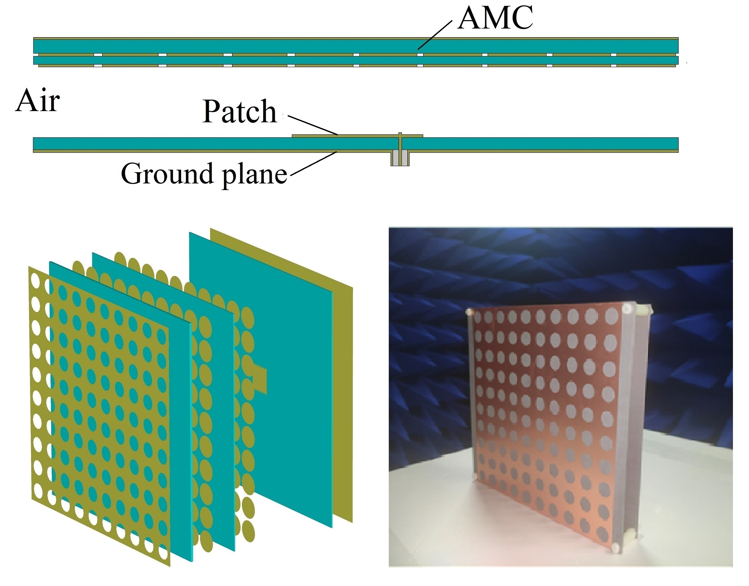
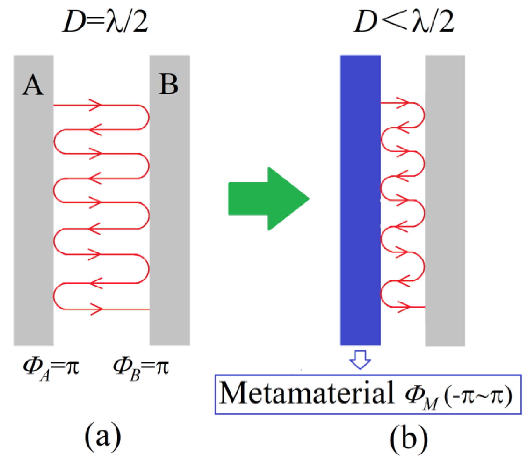
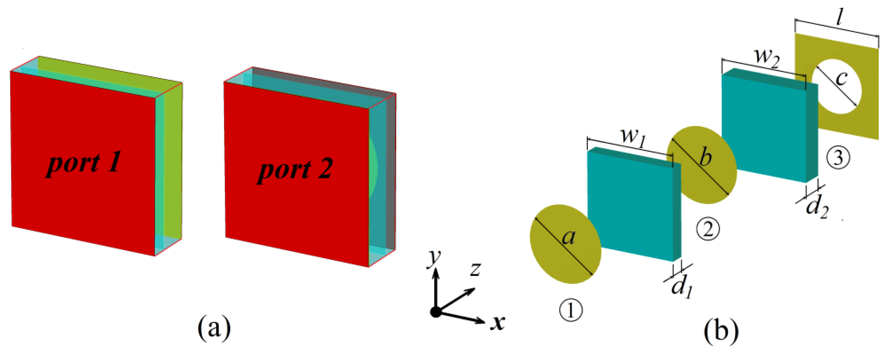
2. Materials and Methods
or D = (ΦA + ΦB) · (λ/4π) + N · (λ/2), N = 0, 1, 2…
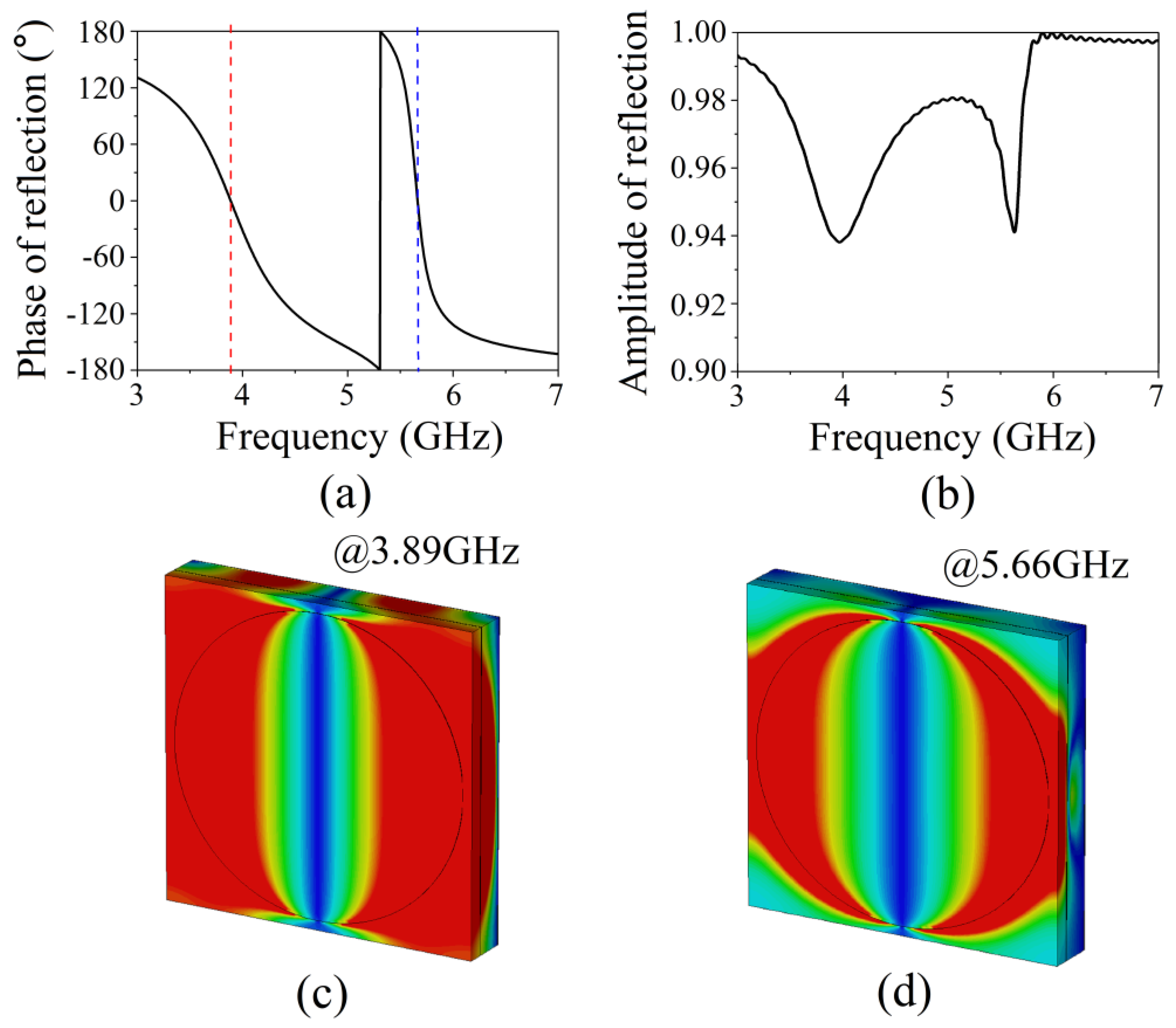
3. Results and Discussion
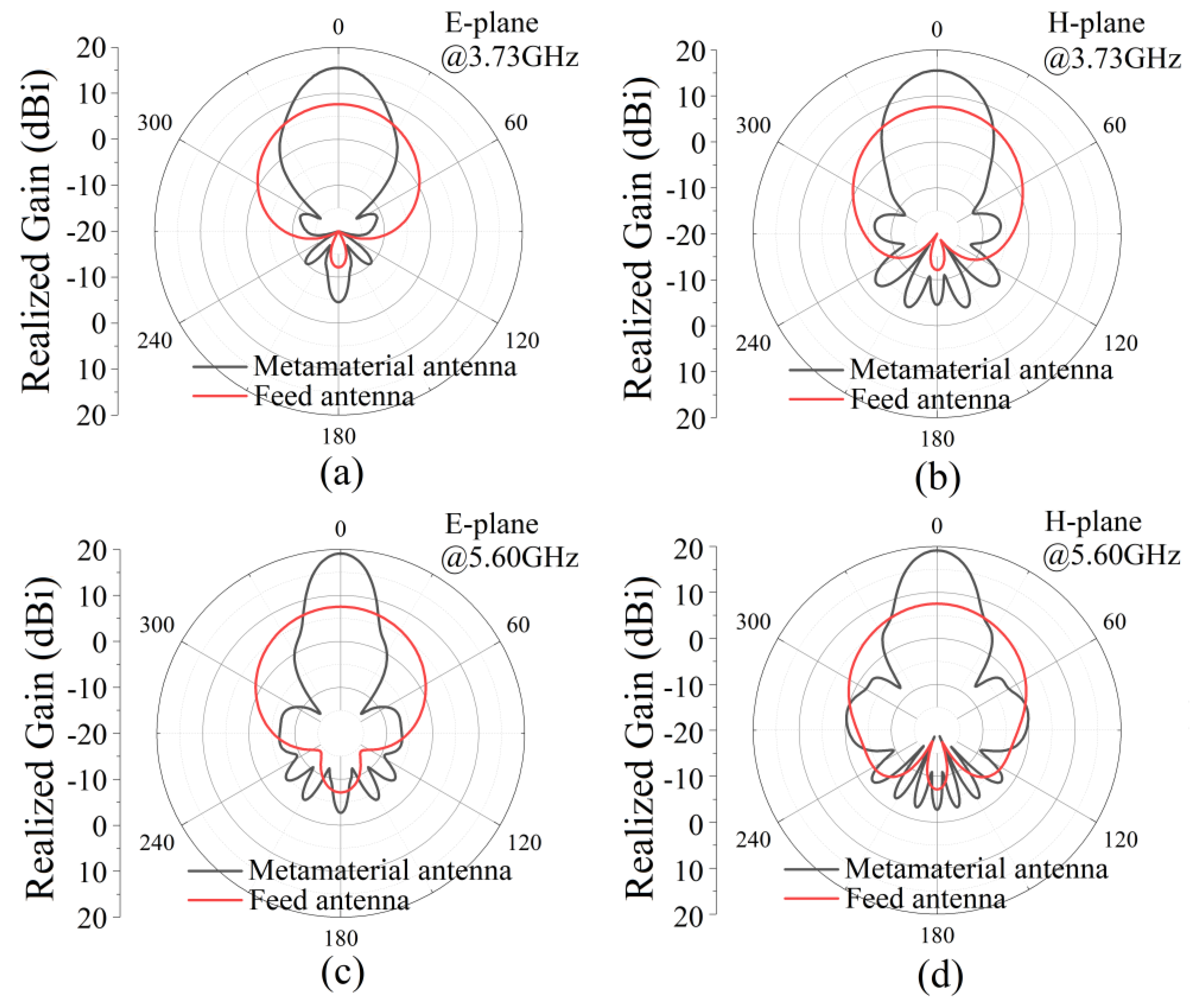
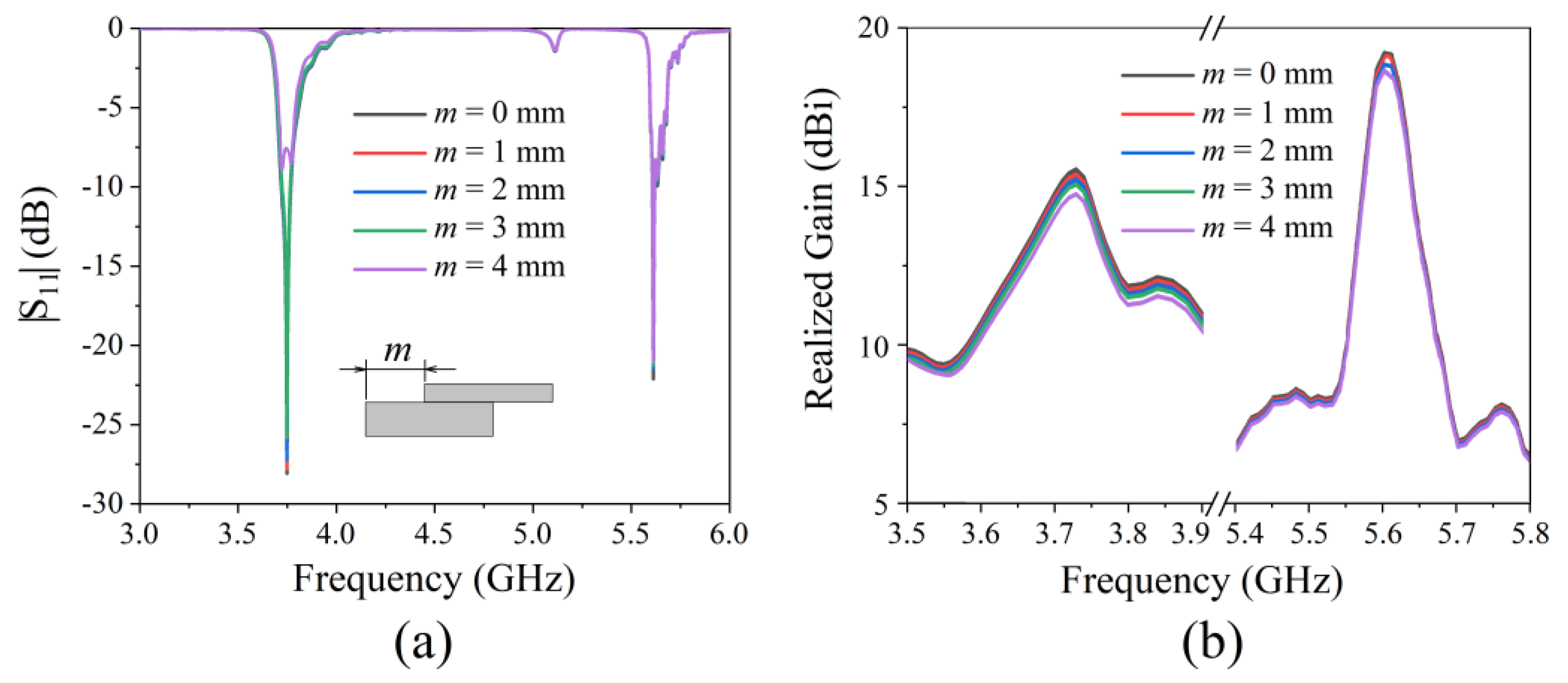
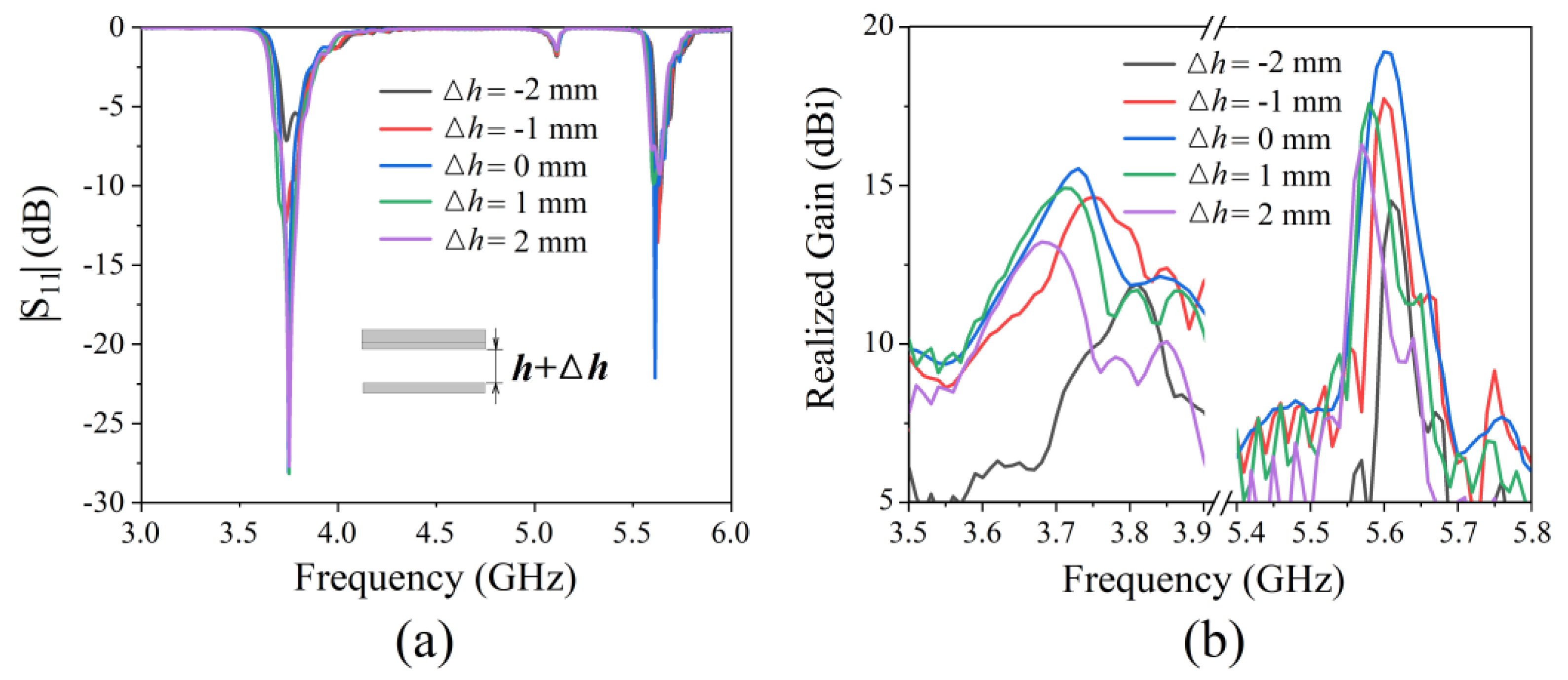
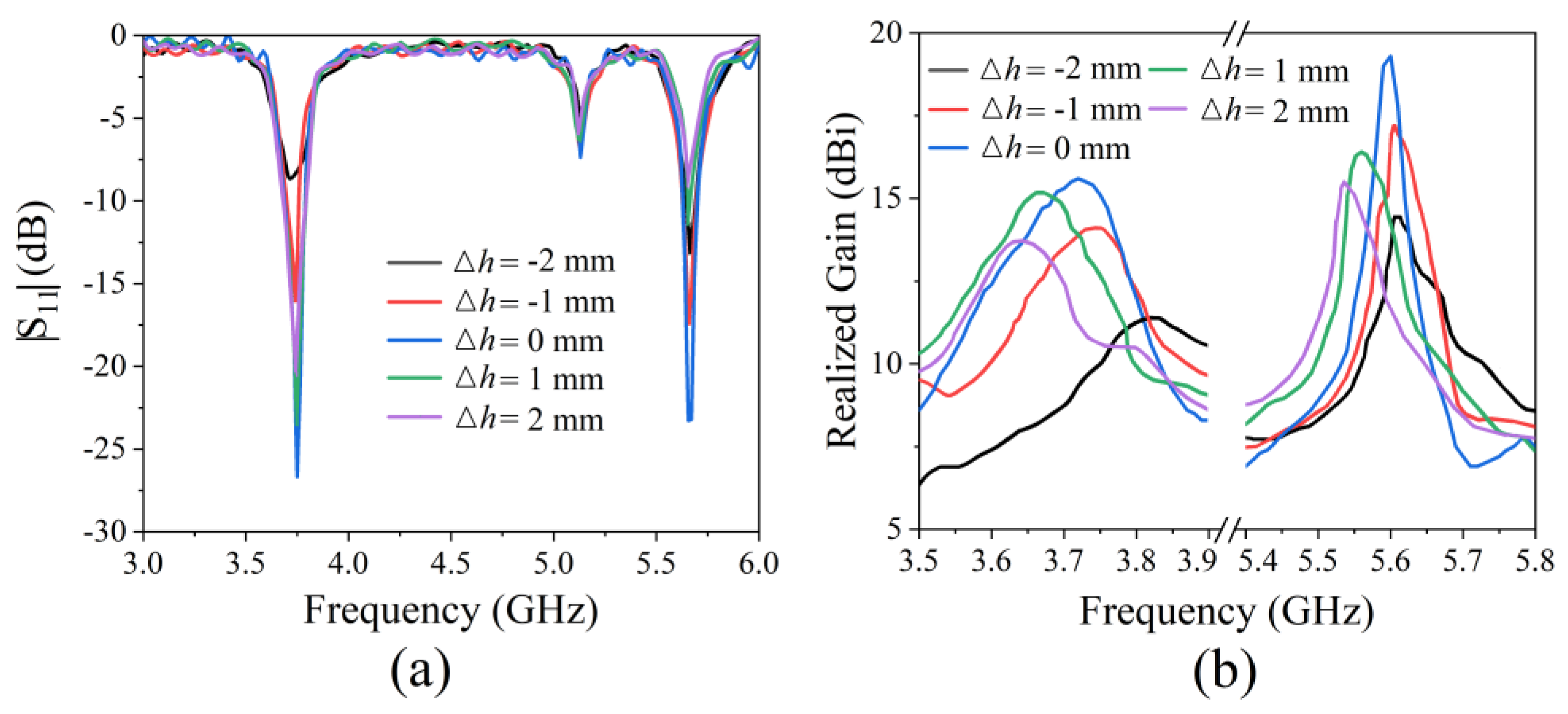
3.1. Results for the Antenna
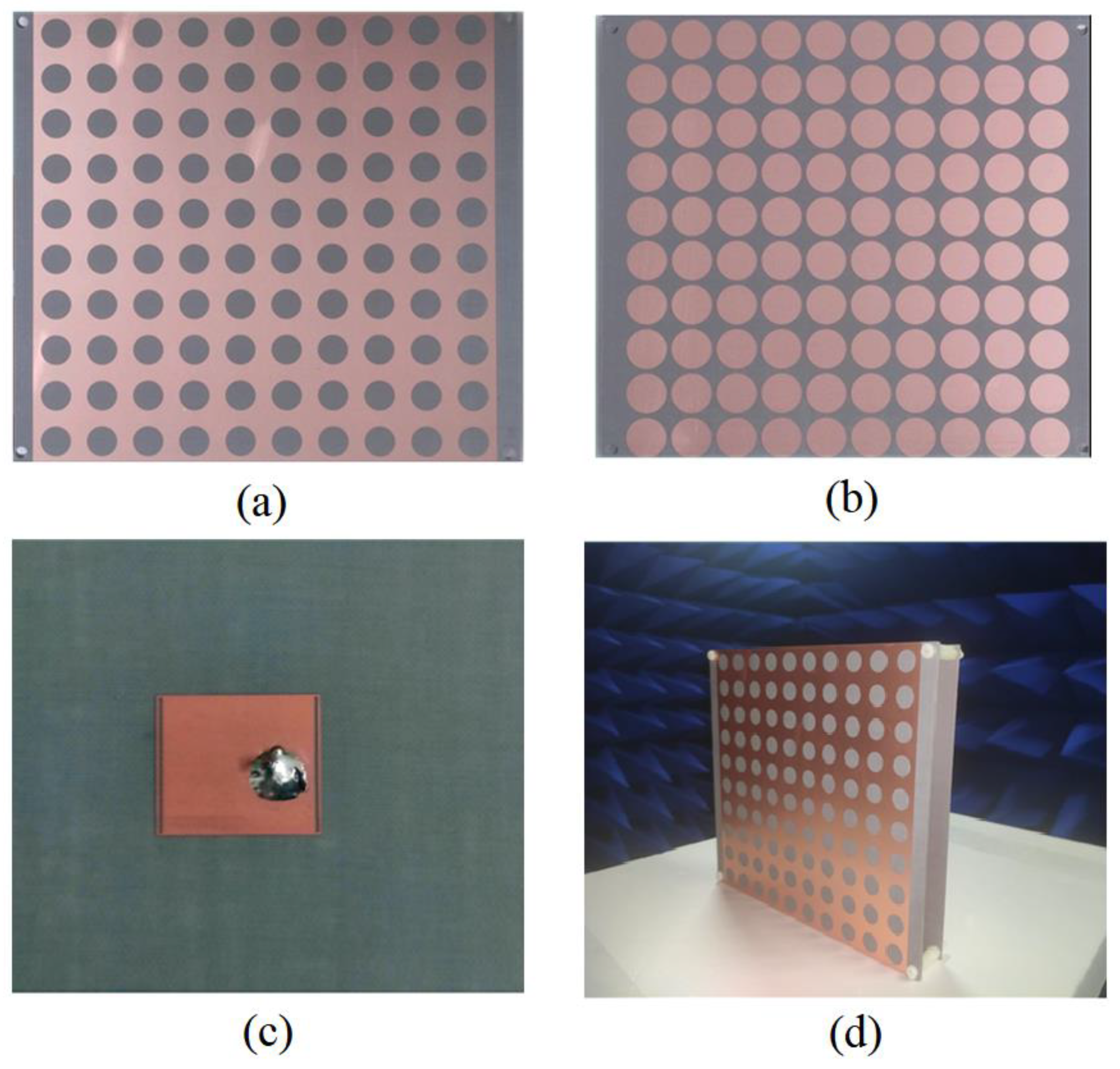
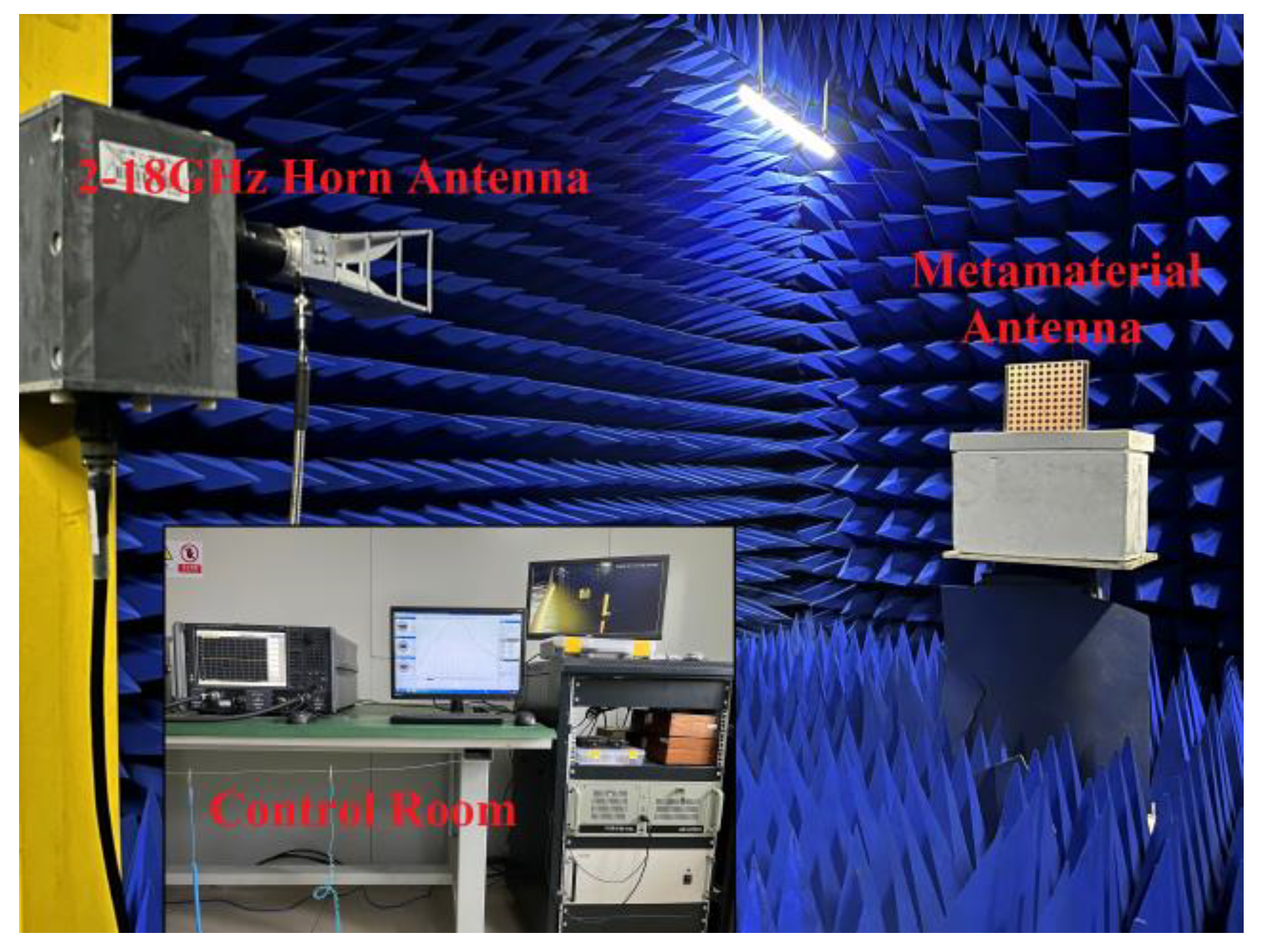
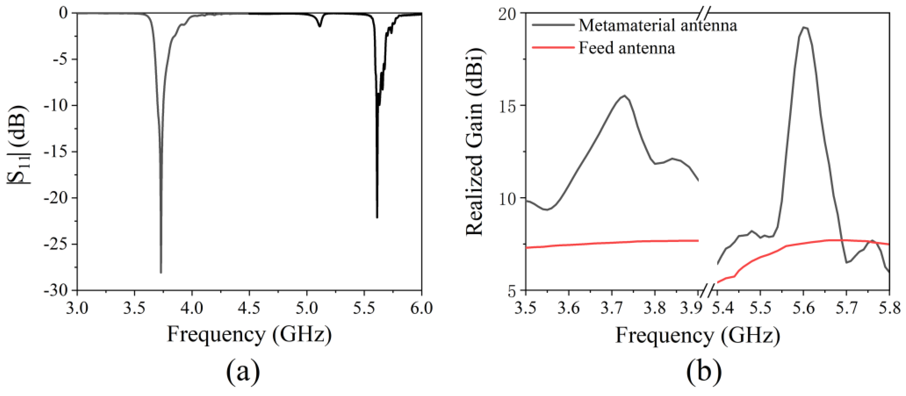
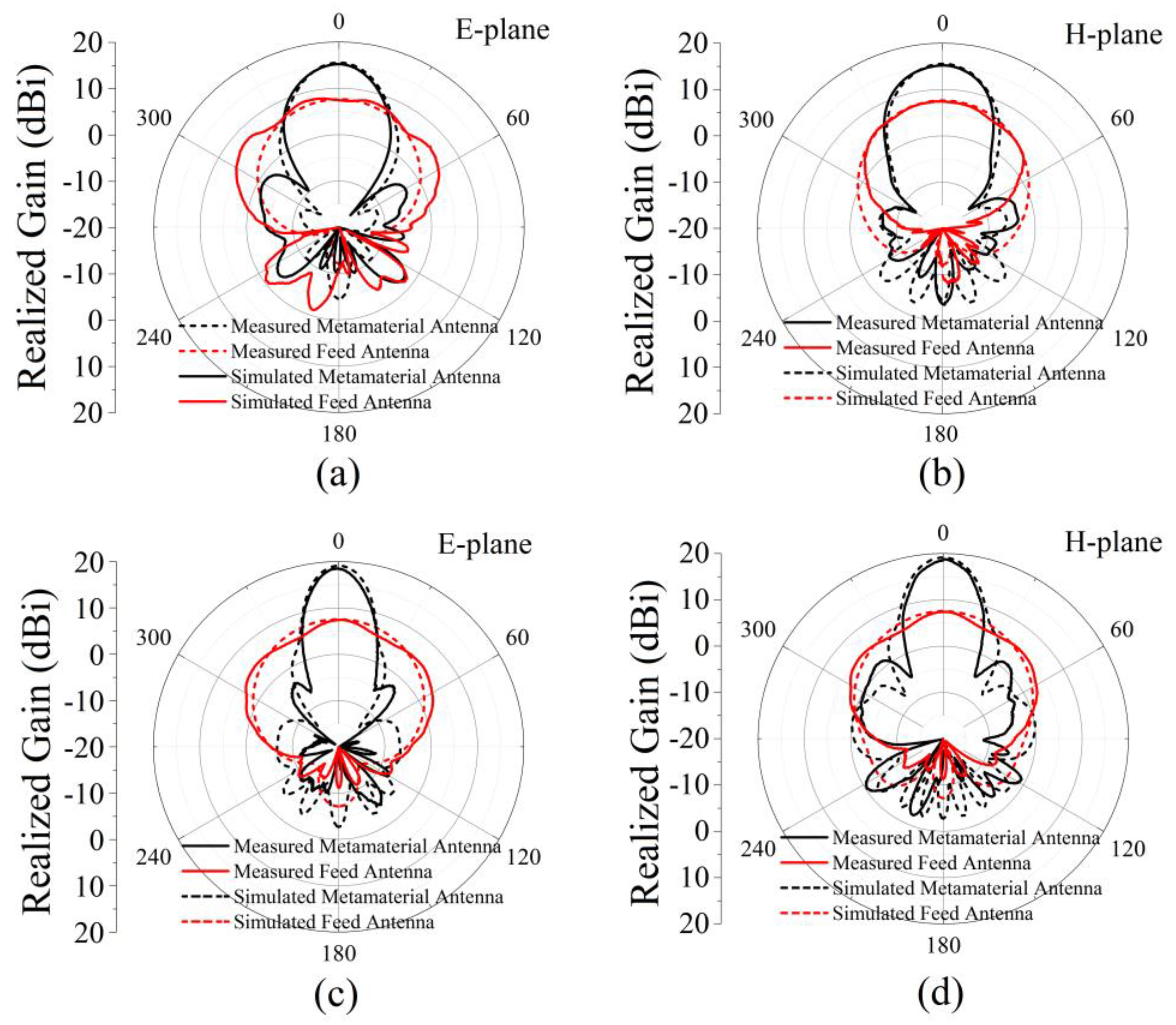
3.2. Experimental Results of the Antenna
4. Conclusions
Author Contributions
Funding
Data Availability Statement
Acknowledgments
Conflicts of Interest
References
- Veselago, V.G. The electrodynamics of substances with simultaneously negative values of ε and μ. Sov. Phy. Usp. 1968, 10, 509–514. [Google Scholar] [CrossRef]
- Smith, D.R.; Padilla, W.J.; Vier, D.C.; Nemat-Nasser, S.C.; Schultz, S. Composite Medium with Simultaneously Negative Permeability and Permittivity. Phys. Rev. Lett. 2000, 84, 4184–4187. [Google Scholar] [CrossRef] [PubMed] [Green Version]
- Smith, D.R.; Pendry, J.B.; Wiltshire, M.C.K. Metamaterials and negative refractive index. Science 2004, 305, 788–792. [Google Scholar] [CrossRef] [PubMed] [Green Version]
- Parimi, P.V.; Lu, W.T.; Vodo, P.; Sridhar, S. Photonic crystals: Imaging by flat lens using negative refraction. Nature 2003, 426, 404. [Google Scholar] [CrossRef] [PubMed]
- Schurig, D.; Mock, J.J.; Justice, B.J.; Cummer, S.A.; Pendry, J.B.; Starr, A.F.; Smith, D.R. Metamaterial Electromagnetic Cloak at Microwave Frequencies. Science 2006, 314, 977–980. [Google Scholar] [CrossRef] [PubMed] [Green Version]
- Chen, T.; Pauly, M.; Reis, P.M. A reprogrammable mechanical metamaterial with stable memory. Nature 2021, 589, 386–390. [Google Scholar] [CrossRef] [PubMed]
- Althuwayb, A.A.; Alibakhshikenari, M.; Virdee, B.S.; Shukla, P.; Limiti, E. Realizing UWB Antenna Array with Dual and Wide Rejection Bands Using Metamaterial and Electromagnetic Bandgaps Techniques. Micromachines 2021, 12, 269. [Google Scholar] [CrossRef] [PubMed]
- Bang, S.; Kim, J.; Yoon, G.; Tanaka, T.; Rho, J. Recent Advances in Tunable and Reconfigurable Metamaterials. Micromachines 2018, 9, 560. [Google Scholar] [CrossRef] [PubMed] [Green Version]
- Ziolkowski, R.W.; Erentok, A. Metamaterial-Based efficient electrically small antennas. IEEE Trans. Antennas Propag. 2006, 54, 2113–2130. [Google Scholar] [CrossRef] [Green Version]
- Alhawari, A.R.H.; Ismail, A.; Mahdi, M.A.; Abdullah, R.S.A.R. Miniaturized ultra-wideband antenna using microstrip negative index metamaterial. Electromagnetics 2011, 31, 404–418. [Google Scholar] [CrossRef]
- Khattak, M.K.; Lee, C.; Park, H.; Kahng, S. RF Channel-Selectivity Sensing by a Small Antenna of Metamaterial Channel Filters for 5G Sub-6-GHz Bands. Sensors 2020, 20, 1989. [Google Scholar] [CrossRef] [Green Version]
- Binion, J.D.; Lier, E.; Hand, T.H.; Jiang, Z.H.; Werner, D.H. A metamaterial-enabled design enhancing decades-old short backfire antenna technology for space applications. Nat. Commun. 2019, 10, 108. [Google Scholar] [CrossRef]
- Huang, Y.; Luo, J.; Pu, M.; Guo, Y.; Zhao, Z.; Ma, X.; Li, X.; Luo, X. Catenary Electromagnetics for Ultra-Broadband Lightweight Absorbers and Large-Scale Flat Antennas. Adv. Sci. 2019, 6, 1801691. [Google Scholar] [CrossRef] [Green Version]
- Alu, A.; Engheta, N. Pairing an epsilon-negative slab with a mu-negative slab: Resonance, tunneling and transparency. IEEE Trans. Antennas Propag. 2003, 51, 2558–2571. [Google Scholar] [CrossRef] [Green Version]
- Feng, T.; Li, Y.; Guo, J.; He, L.; Li, H.; Zhang, Y.; Shi, Y.; Chen, H. Highly localized mode in a pair structure made of epsilon-negative and mu-negative metamaterials. J. Appl. Phys. 2008, 104, 013107. [Google Scholar] [CrossRef]
- Liu, Y.; He, L.; Dong, L.; Liu, L.; Shi, Y.; Yang, C. Multi-Channeled filtering properties of the sandwich structures composed of epsilon-negative metamaterials. J. Appl. Phys. 2013, 114, 608–610. [Google Scholar] [CrossRef]
- Wang, Z.; Xie, P.; Fan, G.; Zhang, Z.; Liu, Y.; Gu, Q.; Fan, R. Epsilon-Negative behavior of BaTiO3/Ag metacomposites prepared by an insitu synthesis. Ceram. Int. 2020, 46, 9342–9346. [Google Scholar] [CrossRef]
- Pendry, J.B.; Holden, A.J.; Stewart, W.J.; Youngs, I. Extremely low frequency plasmons in metallic mesostructures. Phys. Rev. Lett. 1996, 76, 4773–4776. [Google Scholar] [CrossRef] [PubMed] [Green Version]
- Long, S.A.; Mcallister, M.W.; Shen, L.C. The Resonant Cylindrical Dielectric Cavity Antenna. IEEE Trans. Antennas Propag. 1983, 31, 406–412. [Google Scholar] [CrossRef]
- Akalin, T.; Danglot, J.; Vanbesien, O.; Lippens, D. A highly directive dipole antenna embedded in a Fabry-Perot type cavity. IEEE Microw. Compon. Lett. 2002, 12, 48–50. [Google Scholar] [CrossRef]
- Liu, Y.; Dai, Y.; Feng, Q.; Shan, Y.; Lei, D.; Xia, Y.; Lu, G.; Liu, F.; Du, G.; Tian, C. Enhanced light-matter interactions in graphene-covered dielectric magnetic mirrors. Opt. Express 2017, 25, 30754–30763. [Google Scholar] [CrossRef]
- Rong, C.; Lu, C.; Tao, L.; Huang, X.; Zeng, Y.; Liu, X.; Liu, M. Equivalent circuit method for Mu-Negative-Magnetic and Mu-Near-Zero metamaterials in wireless power transfer system. IET Power Electron. 2020, 13, 3056–3064. [Google Scholar] [CrossRef]
- Song, H.; Sun, L.; Wang, G. Tunable perfect magnetic mirrors and retroreflectors in terahertz band. Opt. Express 2020, 28, 753–759. [Google Scholar] [CrossRef]
- Shin, C.S.; Qing, D.; Deng, Z.; Hemmer, P.P. Enhancement of electromagnetic fields with subwavelength microwave resonators. Phys. Rev. B 2005, 72, 193102. [Google Scholar] [CrossRef]
- Engheta, N. An idea for thin subwavelength cavity resonators using metamaterials with negative permittivity and permeability. IEEE Antenn. Wirel. Propag. Lett. 2002, 1, 10–13. [Google Scholar] [CrossRef] [Green Version]
- Feresidis, A.P.; Goussetis, G.; Wang, S.; Vardaxoglou, J.C. Artificial magnetic conductor surfaces and their application to low-profile high-gain planar antennas. IEEE Trans. Antennas Propag. 2005, 53, 209–215. [Google Scholar] [CrossRef] [Green Version]
- Ourir, A.; Lustrac, A.D.; Lourtioz, J.M. All-Metamaterial-Based subwavelength cavities (λ/60) for ultrathin directive antennas. Appl. Phys. Lett. 2006, 88, 084103. [Google Scholar] [CrossRef]
- Sun, Y.; Chen, Z.; Zhang, Y.; Chen, H.; See, T. Subwavelength substrate-integrated fabry-pérot cavity antennas using artificial magnetic conductor. IEEE Trans. Antennas Propag. 2012, 60, 30–35. [Google Scholar] [CrossRef]
- Lu, G.; Wang, W.; Yan, F.; Diao, C.; Zhou, X.; Wu, Z.; Liu, F.; Sun, Y.; Du, G.; Chen, Y. Large area subwavelength cavity antenna with planar metamaterials. AIP Adv. 2019, 9, 025032. [Google Scholar] [CrossRef] [Green Version]
- Hu, Y.; Wang, Y.Z.; Yan, Z.; Zhou, H. A high-gain circularly polarized Fabry-Perot antenna with chiral metamaterial-based circular polarizer. Microw. Opt. Technol. Let. 2019, 62, 906–911. [Google Scholar] [CrossRef]
- Katare, K.K.; Chandravanshi, S.; Biswas, A.; Akhtar, M.J. Beam-Switching of Fabry-Perot cavity antenna using asymmetric reflection phase response of bianisotropic metasurface. IET Microw. Antennas Propag. 2019, 13, 842–848. [Google Scholar] [CrossRef]
- Bozzi, M.; Georgiadis, A.; Wu, K. Review of substrate-integrated waveguide circuits and antennas. IET Microw. Antennas Propag. 2011, 5, 909–920. [Google Scholar] [CrossRef]
- Chaturvedi, D.; Kumar, A.; Raghavan, S. Wideband HMSIW-based slotted antenna for wireless fidelity application. IET Microw. Antennas Propag. 2019, 13, 258–262. [Google Scholar] [CrossRef]
- Kumar, A.; Al-Hasan, M.J. A coplanar-waveguide-fed planar integrated cavity backed slotted antenna array using TE33 mode. Int. J. RF Microw. Comput.-Aided Eng. 2020, 30, e22344. [Google Scholar] [CrossRef]
- Kumar, A. Wideband circular cavity-backed slot antenna with conical radiation patterns. Microw. Opt. Technol. Lett. 2020, 62, 2390–2397. [Google Scholar] [CrossRef]
- Smith, D.R.; Schultz, S.; Markos, P.; Soukoulis, C.M. Determination of effective permittivity and permeability of metamaterials from reflection and transmission coefficients. Phys. Rev. B 2001, 65, 195104. [Google Scholar] [CrossRef] [Green Version]
- Maci, S.; Gentili, G.B. Dual-Frequency patch antennas. IEEE Antennas Propag. Mag. 1997, 39, 13–20. [Google Scholar] [CrossRef] [Green Version]
- Iqbal, A.; Al-Hasan, M.; Basir, A.; Mabrouk, B.; Nedil, M.; Yoo, H. Biotelemetry and Wireless Powering of Biomedical Implants Using a Rectifier Integrated Self-Diplexing Implantable. Antenna. IEEE Trans Antennas Technol. 2021, 67, 3438–3451. [Google Scholar] [CrossRef]
- Kumar, A.; Althuwayb, A.A. SIW Resonator Based Duplex Filtenna. Antennas Wirel. Propag. Lett. 2021, 20, 2544–2548. [Google Scholar] [CrossRef]
- Khan, A.A.; Mandal, M.K. Compact self-diplexing antenna using dual-mode SIW square cavity. IEEE Antennas Wirel. Propag. Lett. 2019, 18, 343–347. [Google Scholar] [CrossRef]
- Chaturvedi, D.; Raghavan, S. Design and experimental verification of dual-fed, self-diplexed cavity-backed slot antenna using HMSIW technique. IET Microw. Antennas Propag. 2019, 13, 380–385. [Google Scholar]
- Kumar, A.; Saravanakumar, M.; Raghavan, S. Dual-Frequency SIW-based cavity-backed antenna. AEU-Int. J. Electron. Commun. 2018, 97, 195–201. [Google Scholar] [CrossRef]


| a (mm) | b (mm) | c (mm) | d1 (mm) | d2 (mm) | w1 (mm) | w2 (mm) | l (mm) |
|---|---|---|---|---|---|---|---|
| 18 | 18 | 13 | 1 | 2 | 20 | 20 | 20 |
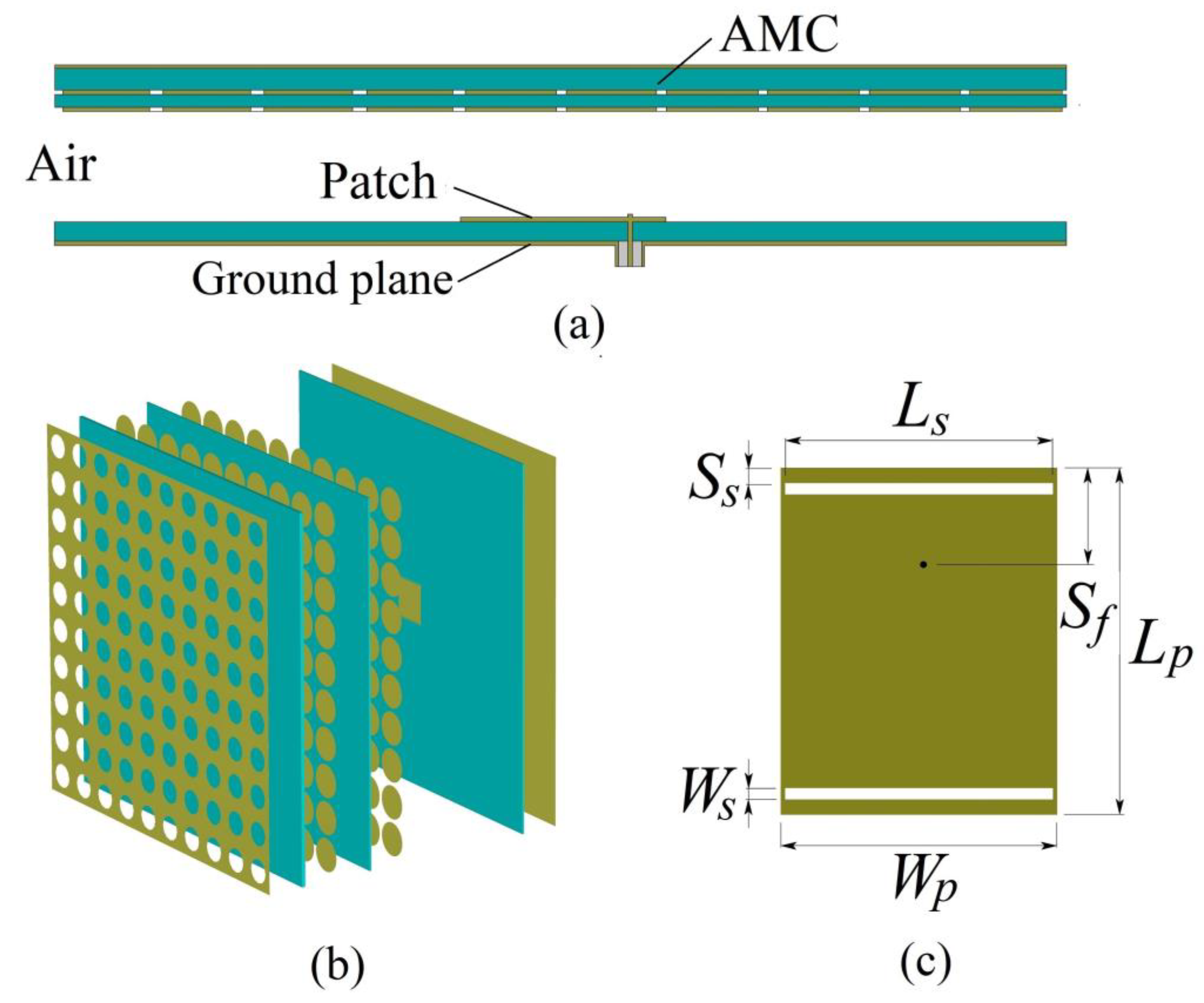
| Wp (mm) | Lp (mm) | Ls (mm) | Ws (mm) | Ss (mm) | Sf (mm) |
|---|---|---|---|---|---|
| 19.6 | 22.9 | 18.9 | 0.5 | 0.3 | 9.1 |
| This Study | REF [38] | REF [39] | REF [40] | REF [41] | REF [42] | |
|---|---|---|---|---|---|---|
| Type of the antenna | Metamaterial antenna | SIW antenna | SIW antenna | SIW antenna | HMSIW antenna | SIW antenna |
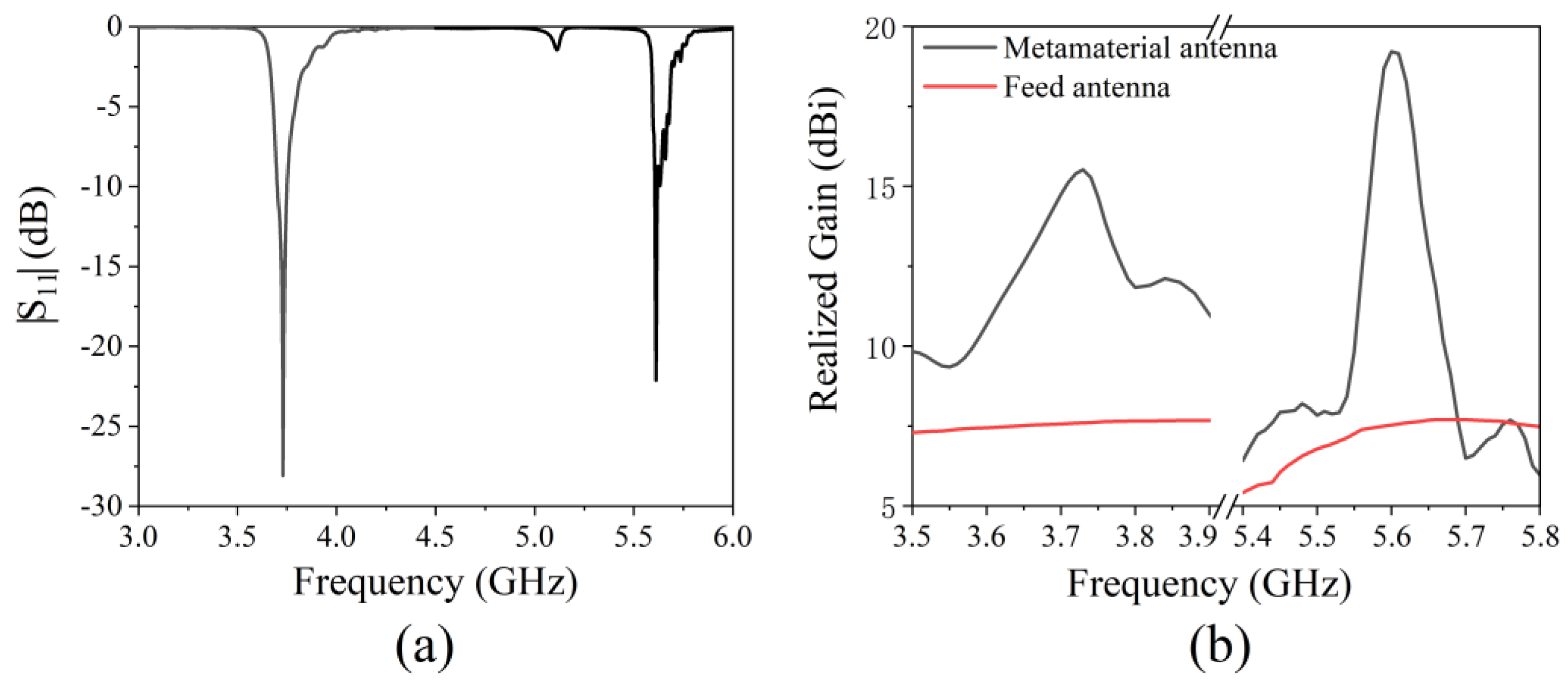
| Frequency (GHz) | (1) 3.75 (2) 5.66 | (1) 0.915 (2) 1.470 | (1) 8.63–8.88 (2) 9.26–9.66 | (1) 9.5 (2) 10.5 | (1) 5.2 (2) 5.8 | (1) 8.50–8.70 (2)13.03–13.84 |
| Max Gain (dBi) | (1) 15.2 (2) 18.9 | (1) −25.2 (2) −19.8 | (1) 3.51 (2) 4.10 | (1) 5.75 (2) 5.95 | (1) 3.31 (2) 4.16 | (1) 5.1 (2) 6.3 |
Publisher’s Note: MDPI stays neutral with regard to jurisdictional claims in published maps and institutional affiliations. |
© 2021 by the authors. Licensee MDPI, Basel, Switzerland. This article is an open access article distributed under the terms and conditions of the Creative Commons Attribution (CC BY) license (https://creativecommons.org/licenses/by/4.0/).
Share and Cite
Lu, G.; Yan, F.; Zhang, K.; Zhao, Y.; Zhang, L.; Shang, Z.; Diao, C.; Zhou, X. A Dual-Band High-Gain Subwavelength Cavity Antenna with Artificial Magnetic Conductor Metamaterial Microstructures. Micromachines 2022, 13, 58. https://0-doi-org.brum.beds.ac.uk/10.3390/mi13010058
Lu G, Yan F, Zhang K, Zhao Y, Zhang L, Shang Z, Diao C, Zhou X. A Dual-Band High-Gain Subwavelength Cavity Antenna with Artificial Magnetic Conductor Metamaterial Microstructures. Micromachines. 2022; 13(1):58. https://0-doi-org.brum.beds.ac.uk/10.3390/mi13010058
Chicago/Turabian StyleLu, Guang, Fabao Yan, Kaiyuan Zhang, Yunpeng Zhao, Lei Zhang, Ziqian Shang, Chao Diao, and Xiachen Zhou. 2022. "A Dual-Band High-Gain Subwavelength Cavity Antenna with Artificial Magnetic Conductor Metamaterial Microstructures" Micromachines 13, no. 1: 58. https://0-doi-org.brum.beds.ac.uk/10.3390/mi13010058