
A Novel Multi-Modality Image Simultaneous Denoising and Fusion Method Based on Sparse Representation


1
Computer Information Systems Department, State University of New York at Buffalo State, Buffalo, NY 14222, USA
2
College of Automation, Chongqing University of Posts and Telecommunications, Chongqing 400065, China
3
Department of Mathematics & Computer and Information Science, Mansfield University of Pennsylvania, Mansfield, PA 16933, USA
*
Author to whom correspondence should be addressed.
Computers 2021, 10(10), 129; https://0-doi-org.brum.beds.ac.uk/10.3390/computers10100129
Submission received: 3 September 2021
/
Revised: 5 October 2021
/
Accepted: 7 October 2021
/
Published: 13 October 2021
(This article belongs to the Special Issue Feature Paper in Computers)
Abstract
:Multi-modality image fusion applied to improve image quality has drawn great attention from researchers in recent years. However, noise is actually generated in images captured by different types of imaging sensors, which can seriously affect the performance of multi-modality image fusion. As the fundamental method of noisy image fusion, source images are denoised first, and then the denoised images are fused. However, image denoising can decrease the sharpness of source images to affect the fusion performance. Additionally, denoising and fusion are processed in separate processing modes, which causes an increase in computation cost. To fuse noisy multi-modality image pairs accurately and efficiently, a multi-modality image simultaneous fusion and denoising method is proposed. In the proposed method, noisy source images are decomposed into cartoon and texture components. Cartoon-texture decomposition not only decomposes source images into detail and structure components for different image fusion schemes, but also isolates image noise from texture components. A Gaussian scale mixture (GSM) based sparse representation model is presented for the denoising and fusion of texture components. A spatial domain fusion rule is applied to cartoon components. The comparative experimental results confirm the proposed simultaneous image denoising and fusion method is superior to the state-of-the-art methods in terms of visual and quantitative evaluations.

1. Introduction
Since an image obtained by a single sensor cannot contain sufficient information of one scene in most cases, additional information from other images captured in the same scene can be used as a necessary complement to reduce the limitations of a single image and enhance the visibility [1,2,3]. Multi-modality image fusion can merge the complementary information from different sensor modalities into the originally captured image [4,5]. Recently, image fusion is widely used in remote sensing, medical imaging, and robotics for the improvement of image quality. Traditional image fusion methods often suppose that there is no noise in source image pairs [6,7,8,9]. However, due to the limitation of sensor-related techniques, image noise always appears in captured images by all types of commercial, professional, and scientific cameras [10,11,12], that can seriously affect image analysis. To improve the image quality, both image denoising and fusion have drawn increasing attention in the image processing area.
In the past decade, similar image processing techniques have been applied to image denoising and fusion and achieved great performance. Wavelet, multi-scale transform, and total variation-based algorithm are the three most widely used methods in both image fusion and denoising [13,14,15]. Sparse representation (SR) has proved to be effective in image denoising and fusion [16,17,18].
Conventional image fusion methods have two steps to process the noise of source images. It does image denoising first, then fuses the denoised images. Since image denoising may decrease both sharpness and contrast of source images, the fusion of denoised images may cause inaccuracy in image details. Additionally, both image fusion and denoising are time-consuming. To further improve the efficiency of image fusion, a number of simultaneous image denoising and fusion methods have been proposed in the past few years. Most simultaneous image fusion and denoising methods are developed based on SR framework.
However, most of existing SR-based simultaneous image fusion and denoising methods do not specialize in image restoration. Both structure and detailed information may be degraded in the denoising process. To optimize this limitation, a novel simultaneous multi-modality image denoising and fusion method is proposed. The proposed method consists of three steps. First, source images are decomposed into cartoon and texture components according to a total variation-based method. In this step, image noise is decomposed into texture components. Second, a GSM-based SR model specialized for image restoration is implemented in the denoising and fusion of texture components, and a spatial domain-based method is applied to the fusion of cartoon components. GSM-based SR model can denoise and sparse code noisy texture components simultaneously. The sparse coded coefficients are fused by using Max-L1 fusion rule, and the fused coefficients can be inversely transformed to a denoised and fused image. Finally, fused texture and cartoon components are integrated into a fused image. The main contributions can be summarized as follows:
- This paper proposes an image denoising and fusion framework, that can fuse and denoise multi-modality images simultaneously. In the proposed framework, image noise is decomposed into texture components, which are fused and denoised simultaneously according to an SR-based method. For the cartoon components, a proper spatial domain fusion rule is implemented. The denoised and fused image can be obtained by integrating fused texture and cartoon components.
- This paper proposes a cartoon-texture decomposition based method to separate image noise and detailed information. In the proposed method, source images are decomposed into cartoon and texture components, where noisy components are decomposed into texture components. Therefore, only the texture components are needed for denoising, this can retain the structure information of cartoon components. Additionally, the detailed and structure information of source images is also decomposed in this step.
- This paper proposes a GSM-based SR model for simultaneous denoising and fusion of texture components. According to a GSM model, SR can remove the noise of texture components, and preserve the image texture information. During the denoising process, sparse coefficients without noisy information can be obtained for fusion.
2. Related Work
2.1. Sparse Representation in Image Denoising
SR technique, that represents image patches as a sparse linear combination of atoms in an over-complete redundant dictionary, is a popular research topic of image processing in recent years [19,20,21,22]. In the image denoising field, SR-based research focuses on two related issues, dictionary construction and statistical modeling of sparse coefficients. For dictionary construction, K-SVD dictionary learning proposed by Elad [23], multi-scale dictionary learning [24], and online dictionary learning by Mairal [25] are the most popular methods. For statistical modeling of sparse coefficients, denoising is conducted in the acquisition process of spare coefficients. Zoran and Wess [26] presented Gaussian mixture models for sparse coefficients in image denoising. Variational Bayesian model and centralized Laplacian model were proposed for image denoising by Ji [27] and Dong [28], respectively. Advanced performance is achieved by these sparse models in image denoising.
2.2. Dictionary Construction and Image Decomposition
For image fusion, the key issue of SR-based image fusion methods can be categorized into dictionary construction and source image decomposition [10,29]. For dictionary construction, Yang and Li [30] applied a fixed DCT dictionary to multi-focus image fusion as the first application of SR-based image fusion. Duan presented a dual-tree complex shearlet dictionary for enhancing the sharpness and contrast of infrared-visible image fusion [31]. K-SVD based dictionary construction methods were implemented in image fusion by Yin [32] and Zhu [33], that improved the performance of details in both fused multi-focus and medical images. Both Kim and Zhu used principal component analysis (PCA) bases of source images to construct dictionary for image fusion [34,35,36]. The constructed dictionary, consisting of PCA bases, was compact and informative, which could decrease the computation cost of image fusion and improve the performance of image fusion. For the decomposition of source images, Kim implemented Gaussian smooth in image decomposition, that strengthened the visual effect of a fused image [34]. Liu introduced multi-scale transform filter to the decomposition of source images, that could improve the performance of SR-based fusion methods in both medical and infrared-visible scenes [29]. Liu and Yin presented a morphological component analysis (MCA) based cartoon-texture decomposition method for image decomposition [37]. They also proposed proper SR-based fusion rules for the fusion of cartoon and texture components. According to the previous discussion, dictionary construction, image decomposition, and models specialized for sparse coefficients are three key issues of both image denoising and fusion.
2.3. Simultaneous Image Denoising and Fusion Method
Li and Yin [10] developed a dictionary learning method based on group-related sparse representation. They used the intrinsic geometrical structure of sparse representation in the form of clusters to build a dictionary. This method can ensure the group structure sparsity of local atoms in different groups of both noise-free and noisy images. Kim and Han [34] presented a joint patch clustering-based dictionary learning (JCPD) method for SR-based image fusion. This method trained a few sub-dictionaries by using PCA-based method, that can construct a denoised compact dictionary for sparse representation. Additionally, according to the image noise rate, Kim and Han set the error tolerance for denoising in the sparse coding process. Therefore, denoised sparse coefficients can be obtained for image fusion. An adaptive sparse representation (ASR) model was proposed by Liu and Wang [38] for simultaneous image denoising and fusion. Liu and Wang used the geometric similarity of image patches to build a few compact sub-dictionaries for both image denoising and fusion. Li [39] proposed a medical image fusion, denoising, and enhancement method based on low-rank sparse component decomposition and dictionary learning (FDESD). Low-rank and sparse regularization terms are first incorporated into the dictionary learning model. Then, a weighted nuclear norm and sparse constraint are imposed on the sparse components to remove noise and preserve texture details. Finally, the fused low-rank and sparse components of source images are combined to construct the fused image. Li [40] proposed an image fusion method based on three-layer decomposition and sparse representation (FDS). The source image is first decomposed into high- and low-frequency components, and then the sparse reconstruct error parameter is adaptively designed and applied to denoising and the fusion of high-frequency components simultaneously. A structure-texture decomposition model is used for low-frequency components. The fused image is obtained by the combination of fused high- and low-frequency components.
Mei [41] first represented image features by using the fractional-order gradient information, and then used two convex variational models to achieve the fusion of noisy images. An alternating direction method of multiplier was applied to optimization of the simultaneous image fusion and denoising. Under the assumption of both RGB and near infrared (NIR) images containing the same well-calibrated spatial resolution, multi-scale wavelet analysis was integrated into a multi-spectral fusion and denoising framework to achieve texture transfer and noise removal [42]. A discrepancy model based on the wavelet scale map was used to solve the discrepancy between RGB and NIR images. NIR-guided Laplacian distributions are applied to model the prior of the fused wavelet coefficients. So, the fusion, denoising, and detail preservation of RGB and NIR image can be achieved simultaneously. Wang [43] integrated an energy function to a variational approach to adjust the pixel values of an input images directly. The corresponding histogram was redistributed to be uniform and the related image noise was removed. A total variational term was used to remove image noise. Additionally, a histogram equalization term was applied to image contrast enhancement, and both image structure and texture were retained by a fidelity term. Yang [44] used both non-locally centralized sparse representation (NCSR) and residual learning of deep CNN (DnCNN) to achieve internal and external denoising, respectively. The simultaneous image denoising and fusion was converted to an adaptive weight-based image fusion of the denoised image details obtained by NCSR and DnCNN. The weights of both pixel intensity change and global gradient of the denoised images are adaptively adjusted. Since image structure varies considerably across different image patches, existing SR-based solutions always need an exceedingly redundant dictionary to achieve the related signal reconstruction. So, visual artifacts and high computational cost are unavoidable in most cases.
3. The Proposed Simultaneous Denoising and Fusion Framework
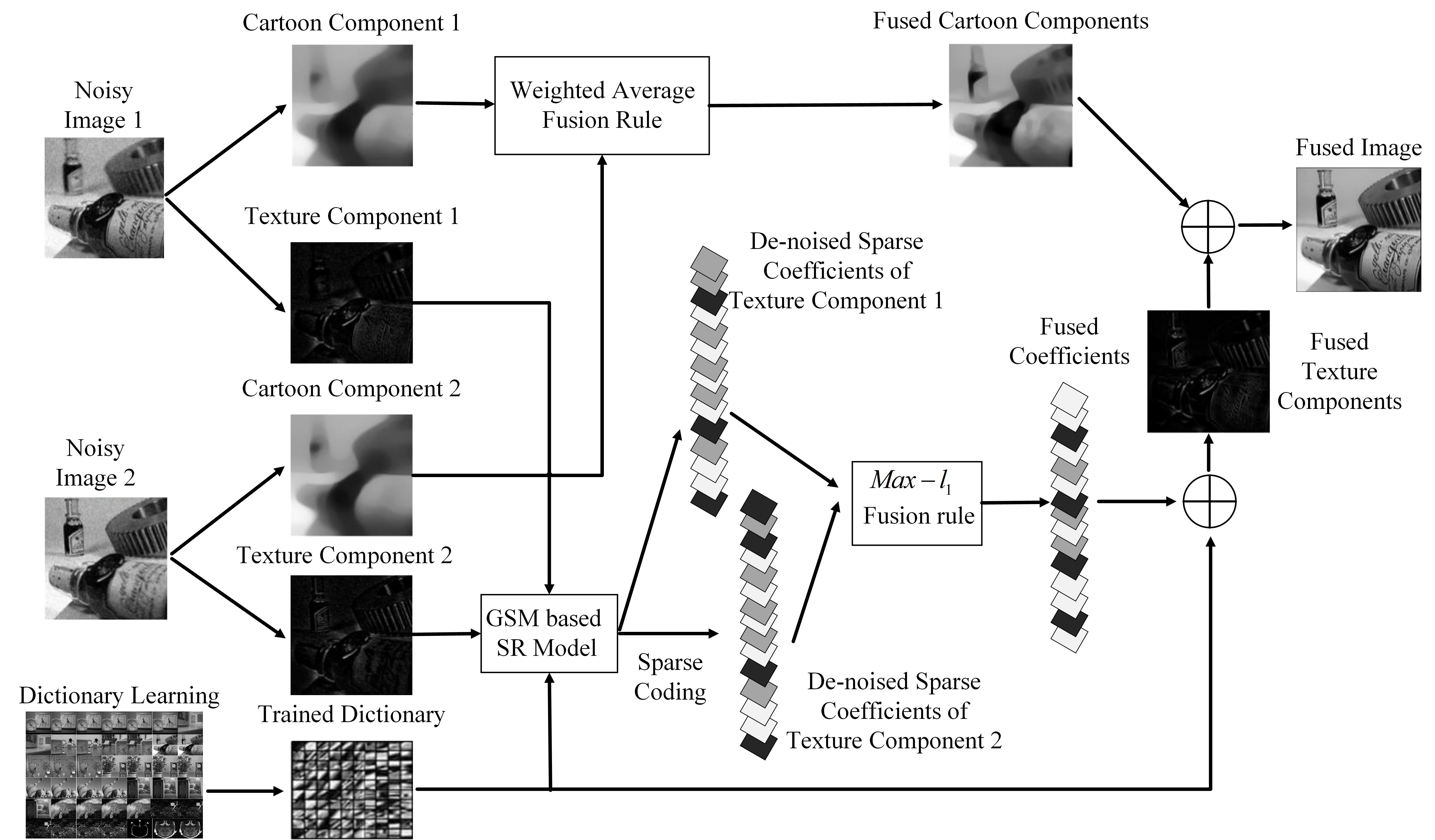
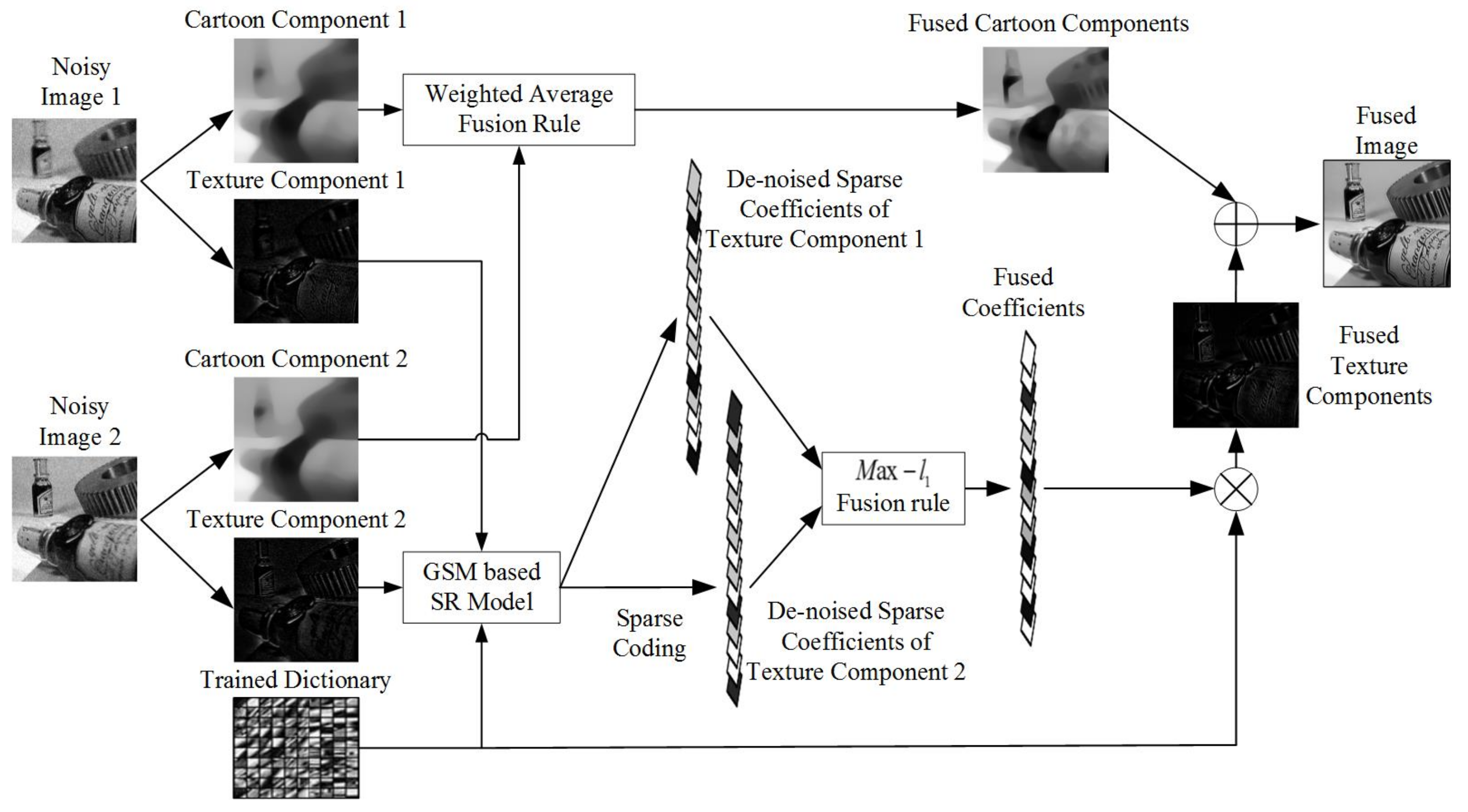
The proposed simultaneous denoising and fusion framework is demonstrated in Figure 1. In the proposed fusion framework, noisy source images are decomposed into cartoon and texture components. After the cartoon-texture decomposition, noisy and detailed information of source images are categorized into texture components. A GSM-based SR model is applied to the denoising and fusion of texture components. In the texture-component fusion, denoised sparse coefficients are first fused by using Max-L1 fusion rule. Then, the fused coefficients are inversely transformed to the denoised and fused texture components. For the cartoon components, texture information-based spatial fusion rule is implemented in cartoon-component fusion. Finally, the fused cartoon and texture components of source images are integrated to generate the fused image.
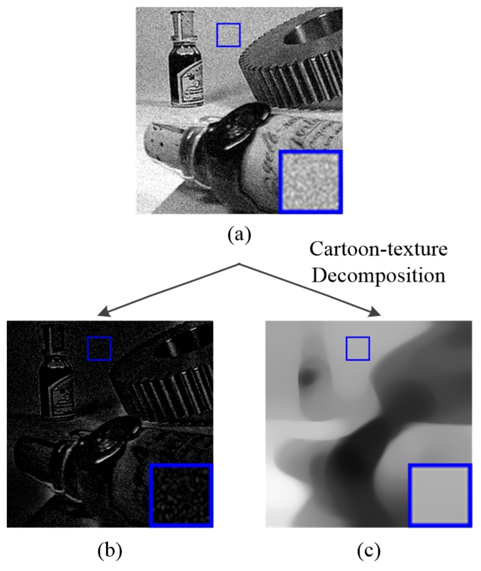
3.1. Image Cartoon-Texture Decomposition
Cartoon-texture image decomposition, that can decompose noisy and detailed information of the image, is widely used in image processing. It is a fundamental step for both image denoising and fusion processes in the proposed framework. For image fusion, cartoon-texture decomposition can separate source images into detailed and structure components. To preserve image information, different fusion rules are applied to detailed and structure components respectively. In the cartoon-texture decomposition, image noise is categorized into texture components. So, the system needs to do the denoising operation on texture components. In the framework, a total variation model is implemented in cartoon-texture decomposition [45]. The details of this model are shown in Equation (1).
where is a vector in G space to represent digital images. BV () represents bounded variation set. and are regularization parameters. u represents the cartoon component of input image. f represents input image. represents the norm of . The description of is demonstrated in Equation (2):
Cartoon component u can be obtained by solving the optimization problem in Equation (1).
When the cartoon component u is calculated, the texture and noise information v can be simply calculated by Equation (3).
The decomposed cartoon and texture components of noisy images are shown in Figure 2.
The noisy information only appears in texture components. In this case, the image denoising problem is converted to a denoising problem of texture components.
3.2. GSM-Based SR Model for the Denoising and Sparse Representation of Texture Components
In the proposed method, GSM-based SR model is employed in the denoising and sparse coding of texture information. GSM-based SR model is a statistical model for sparse representation, which is proposed by Dong [46].
The GSM model decomposes the coefficient vector into the point-wise product of a Gaussian vector and a hidden scalar multiplier , such as , where is the positive scaling variable with probability . In GSM-based SR model, sparse coefficient can be obtained by the specification of sparse prior . The sparse prior term can be expressed as Equation (4),
where and can be decomposed as and respectively. is a diagonal matrix of , where .
For the image denoising problem, a noisy image can be represented as a degraded version of the origin image. The degraded image can be modeled as Equation (5)
where y and x are degraded and original image respectively. is additive white Gaussian noise observing .
According to the GSM statistics model shown in Equation (4) and the image degraded model shown in Equation (5), the denoising and reconstruction problem of texture components of image patch l can be formulated as Equation (6).
where denotes the data matrix formed by an image patch. denotes a matrix extracting the l-th patch from x. D is the dictionary consisting of the PCA bases of all input texture components of image patches. and represent the first and second order statistics of GSM-based SR model for the l-th patch from x. L is the total number of patches. is a small positive number for numerical stability.
To solve Equation (6), an iterative SR-based method, that is made up of two isolated optimization problems, is implemented. For the first optimization problem, B and are fixed to obtain x. When B and are fixed, is also fixed. Therefore, Equation (6) becomes an optimization problem as Equation (7).
For the second optimization problem, x is fixed to solve B and . When x is fixed, Equation (6) can be transformed to Equation (9).
According to Dong’s method [46], this problem can be divided into two sub-problems that use the fixed B and to solve and B respectively. When is fixed, B can be obtained by Equation (10).
As both terms of Equation (10) are , it is a classical Wiener filtering, that can be solved by Equation (11).
To solve the optimization problem in Equation (12), this paper supposes . According to Dong’s method, can be calculated by Equation (13).
where and are shown in Equation (14).
is demonstrated in Equation (15).
Given the above steps, the noisy information of source images can be eliminated. Simultaneously, image information is sparse coded into spare coefficients for the fusion of coefficients.
3.3. Details of Fusion Process
Supposing there are n noisy source images for multi-modality image fusion, the fusion process is summarized as follows. In the proposed framework, texture components of each noisy source image are denoised iteratively in the sparse coding process. In each iteration, the dictionary used in sparse coding is obtained by calculating PCA bases of all the source images. When the iteration reaches the maximum number, sparse coefficients can be obtained for fusion. After the coefficients are fused, the fused image can be easily obtained by the reconstruction of the fused coefficients. The whole denoising and fusion process of texture components is demonstrated in Algorithm A1 (shown in Appendix A).
In this work, the outer loop number k is set to 6 and the inner loop number j is set to 3 for the elimination of noisy information. According to the texture components of all the fused image patches, the texture components of the fused image can be obtained. The presented texture information fusion model can eliminate the noise in the texture components of noisy images in the spare coding process for approximating noise-free sparse coefficients of texture components. Noise in the fused result can be suppressed by fusing the approximated coefficients of texture information. This is the major contribution of the presented SR model.
To preserve the structure information of all source images, a weighted average fusion method is applied to the fusion of cartoon components. The weight of each cartoon component can be calculated by Equation (16),
where represents cartoon component of r-th image patch of k-th source image. represents the fused cartoon component of r-th image patch. , represents the r-th denoised patch of the texture components of the k-th source image. When the cartoon-component patches are fused, they are combined to form a fused cartoon-component image . In the proposed cartoon-component fusion rule, when the amount of the texture components of a patch from one source image is larger than the corresponding one from the other image, its cartoon component is given a higher percentage in the final fused image. The fused and denoised image can be obtained by simply adding and by Equation (17)
4. Experiments and Analyses
4.1. Experiment Setup
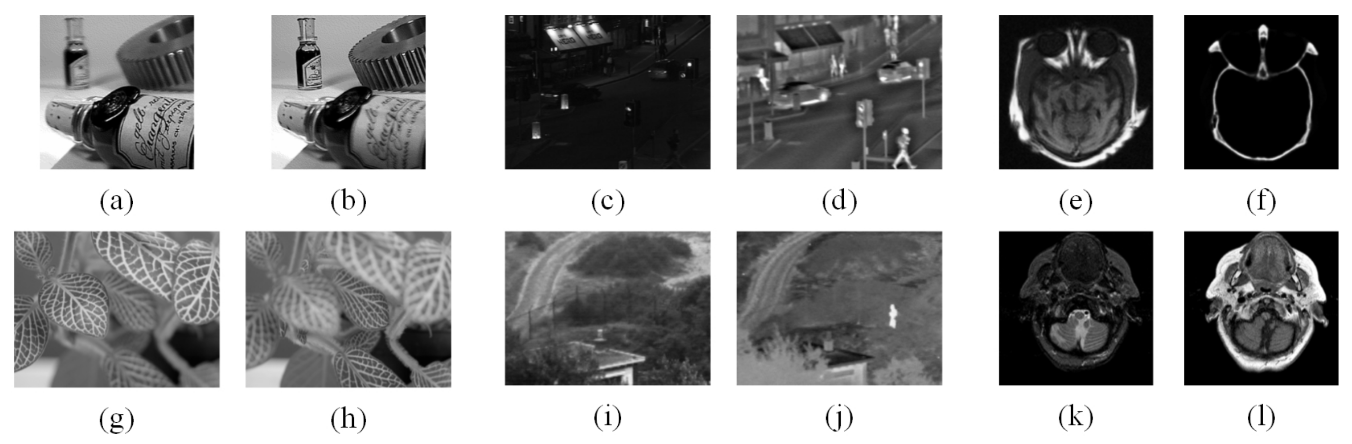
In comparative experiments, 20 pairs of multi-focus images, 20 pairs of infrared-visible, and 20 pairs of medical images are used to test the fusion performance respectively. The multi-focus and infrared-visible image pairs have resolution. The resolution of medical image pairs is . Parts of several representative images are shown in Figure 3. (a)&(b), and (g)&(h) are two typical multi-focus image pairs. Two medical image pairs are shown in (c)&(d), and (i)&(j) respectively. (e)&(f), and (k)&(l) demonstrate two infrared-visible image pairs respectively. All of image pairs used for testing are collected by Liu [29] and can be downloaded at quxiaobo.org. Gaussian noise is injected to source images for simultaneous fusion and denoising testing. In the following comparative experiments, the levels of noise are set to four fixed values as . All the experiments are programmed in MATLAB 2016b on a desktop with an Intel(R) Core(TM) i9-7900X @ 3.30 GHz CPU and 16.00 GB RAM.
Eight mainstream objective evaluation metrics are implemented in the performance evaluation of all fused images. These metrics include Tsallis entropy () [47,48], nonlinear correlation information entropy () [49], edge retention () [50], image fusion metric based on phase congruency () [51], mutual information () [52,53], Yang proposed fusion metric () [48,54], Chen-Blum metric () [48,55], and visual information fidelity for fusion () [56]. These objective metrics can evaluate different characteristics of fused images. is a divergence measure, that can evaluate the degree of dependence between two discrete signals. is a nonlinear correlation matrix, that measures the nonlinear correlation coefficient (NCC) of input images and the fused image. metric is a gradient-based quality index to measure how well the edge information of source images is conducted to the fused image. is an image phase congruency based evaluation metric to evaluate the corner and edge information of the fused image. is a metric to evaluate information similarity between source images and the fused image. is a structure-similarity based image fusion performance metric, that can measure the structure similarity between source images and the fused image without a reference image. is a human perception inspired fusion metric, that can obtain a contrast-preservation value of the fused image. is also a human perception inspired fusion metric. It quantifies the information shared between test and fused images based on Natural Scene Statistics (NSS) theory and Human Visual System (HVS) model. When the values of previously mentioned objective metrics get bigger, the fused results are indicated to be better.
4.2. Comparison of Simultaneous Fusion and Denoising Methods
In this experiment, the simultaneous denoising and fusion performance of the proposed framework is compared with two existing state-of-the-art methods, FDESD [39] and FDS [40]. For all sparse-representation based methods, the size of each image patch is set to and the overlap is set to 6 in all the experiments. The dictionary size of FDESD and the proposed method is set to 256.
4.2.1. Multi-Focus Image Fusion
Due to the limitation of focus range, camera lens have difficulty in capturing an all-on-focus image in a shutter. Multi-focus image fusion technique is proposed to solve this issue. Moreover, the parameter settings of image sensors can cause multi-focus images to be affected by noise. Thus, simultaneous denoising and fusion can relieve the limitations of lens focus range. 14 image pairs are used in the multi-focus image fusion experiments. To test the simultaneous denoising and fusion performance, these image pairs are tested as original image pairs and noisy image pairs. The noise levels are set to and 50 respectively.
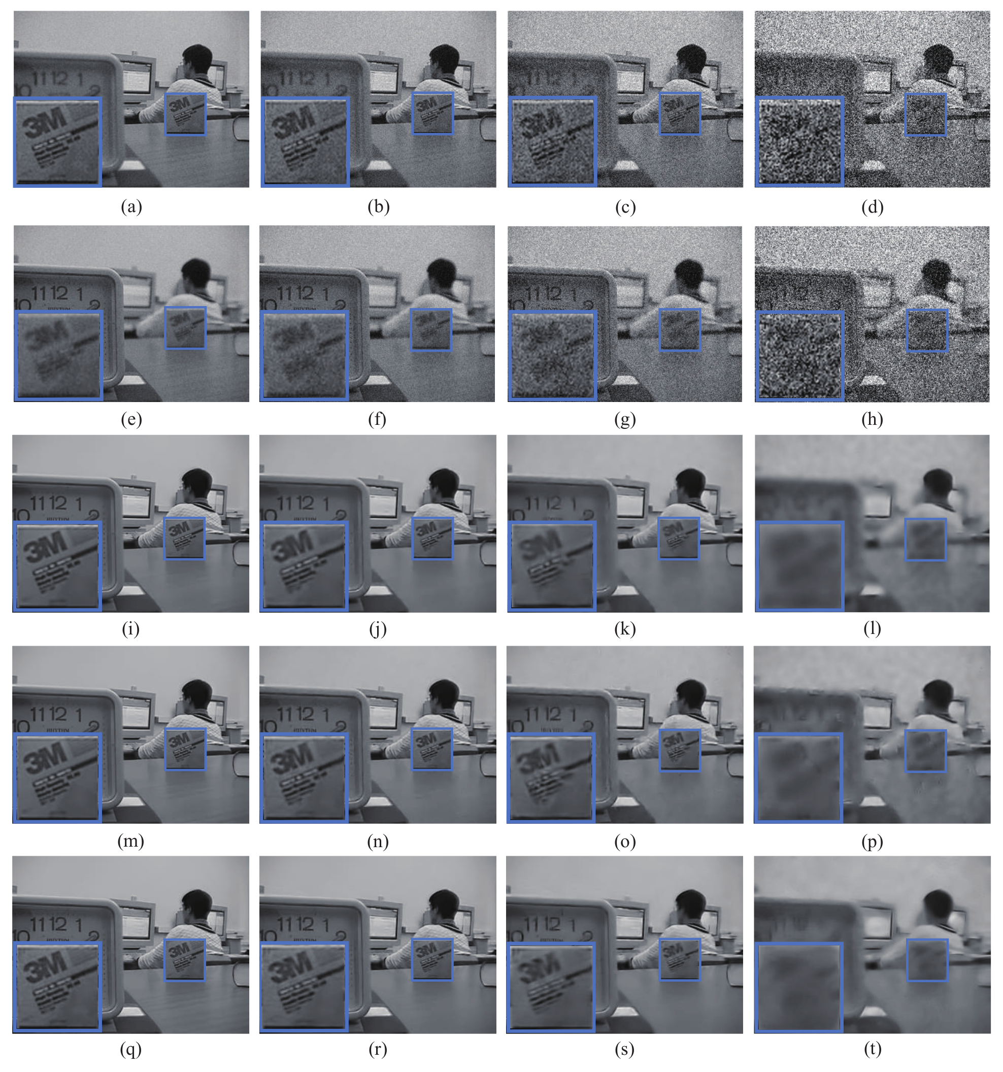
The selected experimental results -1: The representative image pair of all multi-focus experiments is shown in Figure 4. Row 1&2 and row 3–5 demonstrate the noised source images and processed images respectively. The noise levels of column 1 to 4 in Figure 4 are set to and 50 respectively.
According to Figure 4, when the noise level is set to , all three methods show similar fusion results. However, as the noise level increases to and , the fused image by FDESD cannot filter all the noise. To facilitate comparisons, local regions enclosed by blue frame in Figure 4 are enlarged and presented in the lower left corner of each fused image. From these close-up views of the labeled regions, it shows that the fusion details produced by the proposed method contain better contrast and sharpness, when the noise level raises to and . Therefore, it confirms that the proposed method achieves the best visual quality in multi-focus image simultaneous fusion and denoising among all three methods.
To assess the fusion performance objectively, eight objective evaluation metrics, i.e., , , , , , , , and , are used in the comparison. The corresponding assessment results are listed in Table 1, where the largest values are highlighted in bold. The proposed method not only achieves the highest scores in the multi-focus image fusion, but also in the other seven measures of all noise levels, that include , , , , , , and . The metric measures the edge retention. The fusion result of FDS obtains higher score in than the proposed method, when the noise level is set to . However, as the noise level raises to and 50, the scores of the proposed method surpass the corresponding scores of FDS. In this case, it concludes that the proposed method yield the best results in the simultaneous image denoising and fusion.
The selected experimental results -2: The representative image pair of all multi-focus experiments is shown in Figure 5. Row 1&2 and row 3–5 demonstrate the noised source images and processed images respectively. The noise levels of column 1 to 4 in Figure 5 are set to and 50 respectively.
According to Figure 5, when the noise level is set to , all three methods show similar fusion results. However, as the noise level increases to and , the fused image by FDESD cannot filter all the noise. To facilitate comparisons, local regions enclosed by blue frame in Figure 5 are enlarged and presented in the lower left corner of each fused image. From these close-up views of the labeled regions, it shows that the fusion details produced by the proposed method contain better contrast and sharpness, when the noise level raises to and . Therefore, it confirms that the proposed method achieves the best visual quality in multi-focus image simultaneous fusion and denoising among all three methods.
To assess the fusion performance objectively, eight objective evaluation metrics, i.e., , , , , , , , and , are used in the comparison. The corresponding assessment results are listed in Table 2, where the largest values are highlighted in bold. The proposed method not only achieves the highest scores in the multi-focus image fusion, but also in the other seven measures of all noise levels, that include , , , , , , and . In this case, it concludes that the proposed method yield the best results in the simultaneous image denoising and fusion.
The average experimental results: The average objective evaluation results of simultaneous multi-focus image denoising and fusion are shown in Table 3. The corresponding results are consistent with the above demonstrated results of two groups of simultaneous multi-focus image denoising and fusion experiments. The proposed method has the best overall performance.
4.2.2. Multi-Modality Medical Image Fusion
Medical images are usually used in medical diagnosis. However, a single-modality medical image can only reflect one aspect of characteristics in medical diagnosis. So, multi-modality medical image fusion can be an effective technique to enhance the accuracy of medical diagnosis. Additionally, medical imaging sensors have limitations and medical images often contain noise. Therefore, simultaneous image denoising and fusion have practical significance in medical image processing. To test the performance of multi-modality medical image simultaneous denoising and fusion, the second experiment compares the fusion results of eight multi-modality medical image pairs. The noise levels of these multi-modality image pairs are set to and 50 respectively.
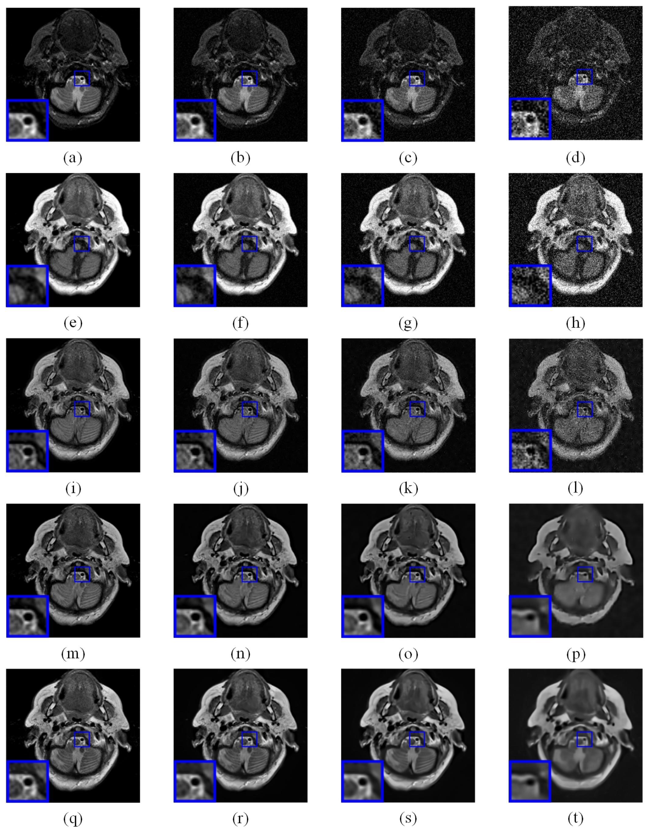
The selected experimental results -1: In Figure 6, row 1&2 and row 3–5 demonstrate the noised source images and processed images respectively. Column 1 to 4 of Figure 6 provide the source images and fusion results with the noise level from to 50 respectively.
The simultaneous denoising and fusion results of representative multi-modality medical image are shown in Figure 6. FDESD can eliminate the image noise at level to 10. But when the noise level raises to and 50, the fused images by using FDESD are still noisy. FDS and the proposed method eliminate image noise at all noise levels. After careful observation, there is some information residue in the magnified regions of processed image by FDS at noise level . In contrast, the processed results of the proposed method exhibit the best visual quality without obvious artifacts and residue at all noise levels.
In comparison with other methods, FDS method can generate edge pleasant fusion results, when the noise level is set to . However, the proposed method outperforms the other two methods in terms of almost all the metrics as shown in Table 4.
The selected experimental results -2: In Figure 7, row 1&2 and row 3–5 demonstrate the noised source images and processed images respectively. Column 1 to 4 of Figure 7 provide the source images and fusion results with the noise level from to 50 respectively.
The simultaneous denoising and fusion results of representative multi-modality medical image are shown in Figure 7. FDESD can only eliminate the image noise at level to 10. The images fused by FDESD contain noise when the noise level raises to and 50. FDS and the proposed method eliminate image noise at all noise levels. After careful observation, there is some information residue in the magnified regions of processed image by FDS at noise level . Table 5 shows the results of eight objective evaluation indicators. In contrast, the processed results of the proposed method exhibit the best visual quality without obvious artifacts and residue at all noise levels.
The average experimental results: The average objective evaluation results of simultaneous multi-modality medical image denoising and fusion are shown in Table 6. The corresponding results are consistent with the above demonstrated results of two groups of simultaneous multi-modality medical image denoising and fusion experiments. The proposed method has better overall performance than FDESD and FDS.
4.2.3. Infrared-Visible Image Fusion
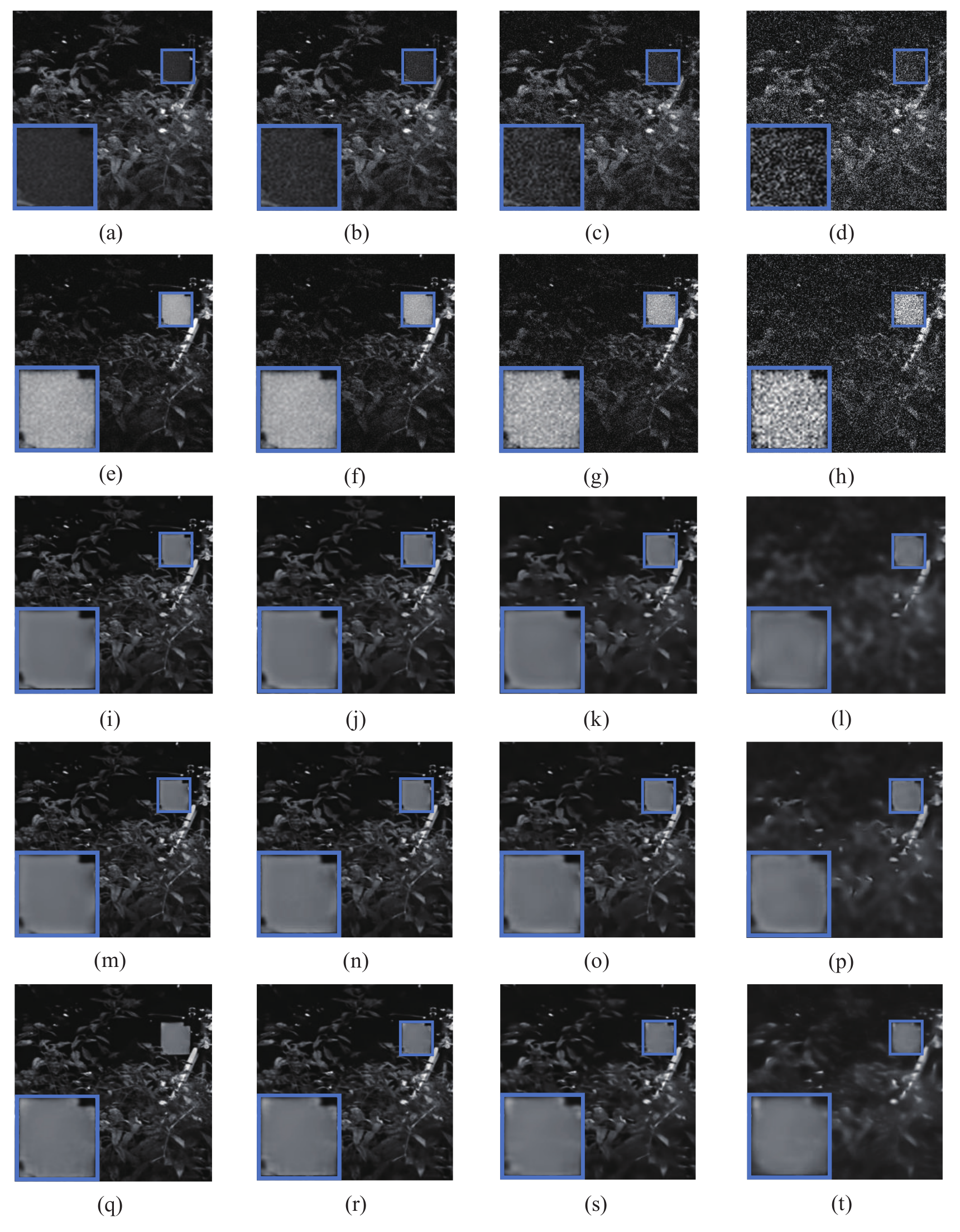
Infrared-visible image fusion is often used in low-light environment for object detection [57]. Due to the sensitivity of camera sensors, photos taken by visible sensors are noisy in low-light environment. Infrared sensors also produce noisy images when the temperature of the infrared sensor rises in the imaging process. Therefore, simultaneous image denoising and fusion have practical significance in infrared-visible image processing. In consequence, simultaneous denoising and fusion technique is necessary for integrating the information of infrared and visible images. Eight infrared-visible image pairs are used in the comparisons of infrared-visible image simultaneous denoising and fusion. The noise levels of infrared-visible image pairs are set to and 50 respectively.
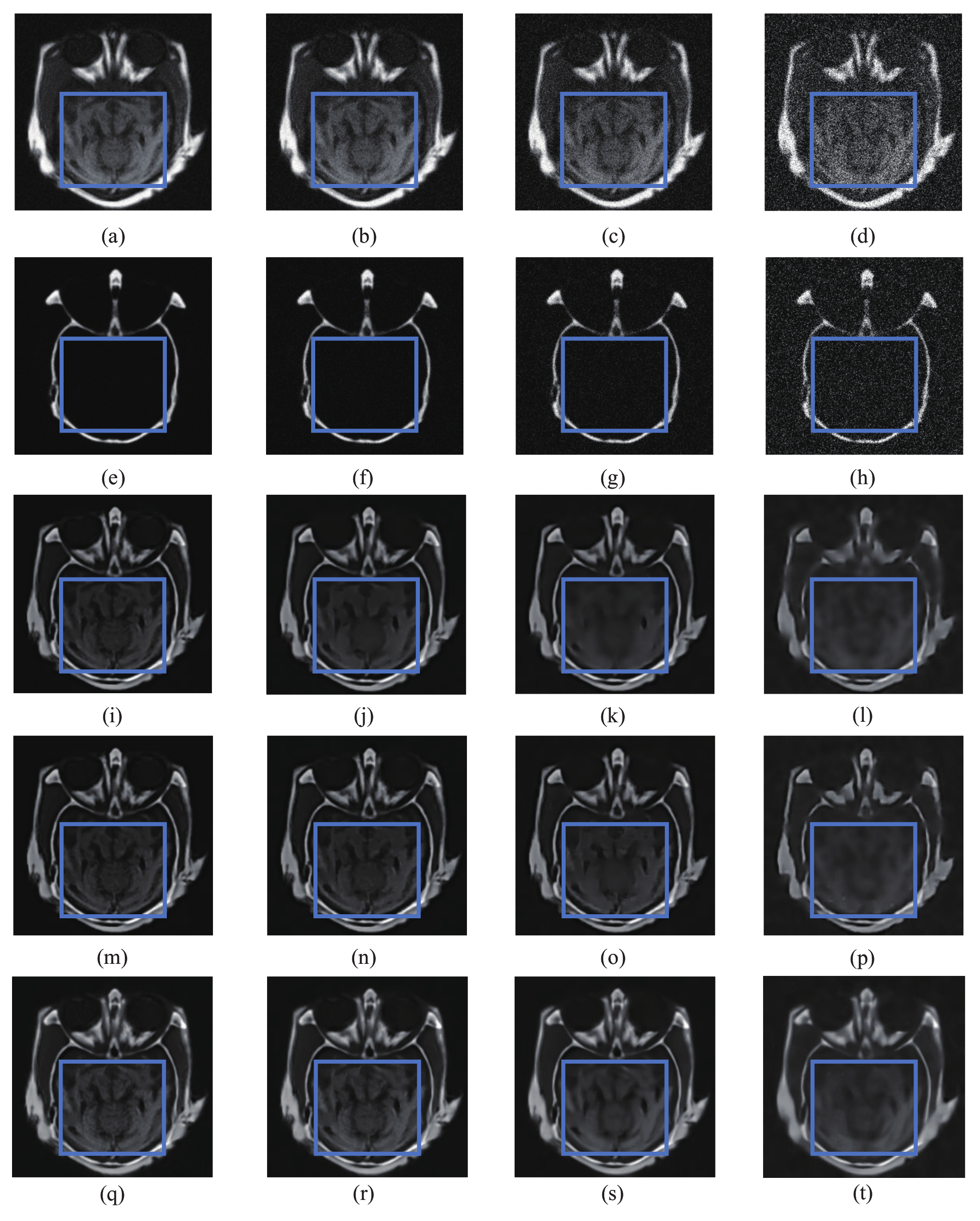
The selected experimental results -1: The fusion results of representative infrared-visible image pairs are shown in Figure 8. The first two rows of Figure 8 are the source infrared-visible image pairs, and the remaining three rows are the processed images. Row 3–5 are the processed images by using FDESD, FDS and the proposed method respectively. From column 1–4, the original and processed image with noise levels of and 50 are presented respectively.
When the noise level is set to , the background is clear in the fusion results of FDESD and FDS. However, when the noise level rises to and 50, the backgrounds of FDESD and FDS become unsharp. Besides that, the contrast of the enlarged object ’walking man’ is low in all the integrated images of FDESD and FDS. The noise is eliminated in all fused images by the proposed method. Moreover, the object ’walking man’ is clear and sharp in the fused images of the proposed method. Hence, the proposed method achieves the best simultaneous denoising and fusion effect among the three methods.
Table 7 presents the average quantitative comparisons of infrared-visible image simultaneous denoising and fusion results. It is obvious that the proposed method shows the best performance in all objective evaluation metrics.
The selected experimental results -2: The fusion results of representative infrared-visible image pairs are shown in Figure 9. The first two rows of Figure 9 are the source infrared-visible image pairs, and the remaining three rows are the processed images. Row 3–5 are the processed images by using FDESD, FDS and the proposed method respectively. From column 1–4, the original and processed image with noise levels of and 50 are presented respectively.
When the noise level is set to , the background is clear in the fusion results of FDESD and FDS. However, when the noise level rises to and 50, the backgrounds of FDESD and FDS become unsharp. Besides that, the contrast of the enlarged object is low in all the integrated images of FDESD and FDS. The proposed method successfully eliminate noise in all fused images. Moreover, the enlarged object is clear and sharp in the image fused by the proposed method. According to the results of eight objective evaluation indicators shown in Table 8, the proposed method achieves the best simultaneous denoising and fusion effect among the three methods.
The average experimental results: The average objective evaluation results of simultaneous infrared-visible image denoising and fusion are shown in Table 9. The corresponding results are consistent with the above demonstrated results of two groups of simultaneous infrared-visible image denoising and fusion experiments. The proposed method has the best overall performance.
4.2.4. Comparison of Computational Efficiency
The average processing time is used to compare the computational efficiency of all three simultaneous denoising and fusion methods. All the tests are implemented in the same platform as described in the experiment setup. In the comparative experiments, the source codes of FDESD [39] and FDS [40] are provided by the original authors. The average processing times of different methods are presented in Table 10.
These results confirm that FDS method is the most efficient method, and the proposed method is much more efficient than FDESD. Although FDS is more efficient than the proposed method, the average processing time of the proposed method is still comparable. FDS uses the original sparse-representation model to eliminate image noise which improves the efficiency of FDS. However, the denoising performance of the original sparse-representation model is not good. Considering the SR model in processing effect and computation efficiency, the proposed method gets the best performance in noisy image fusion among all three methods.
4.3. The Proposed Method Compares with Conventional Image Fusion and Denoising Method
In further testing, the proposed method is compared with the conventional image fusion and denoising method in noisy image fusion. The separated denoising and fusion method (SDF) consisted of a state-of-the-art SR-based image denoising method [58] and one of the best SR-based fusion frameworks [29] are implemented in twenty comparative experiments of each image type. The patch size is set to , and the overlap is set to 6 in all the experiments.
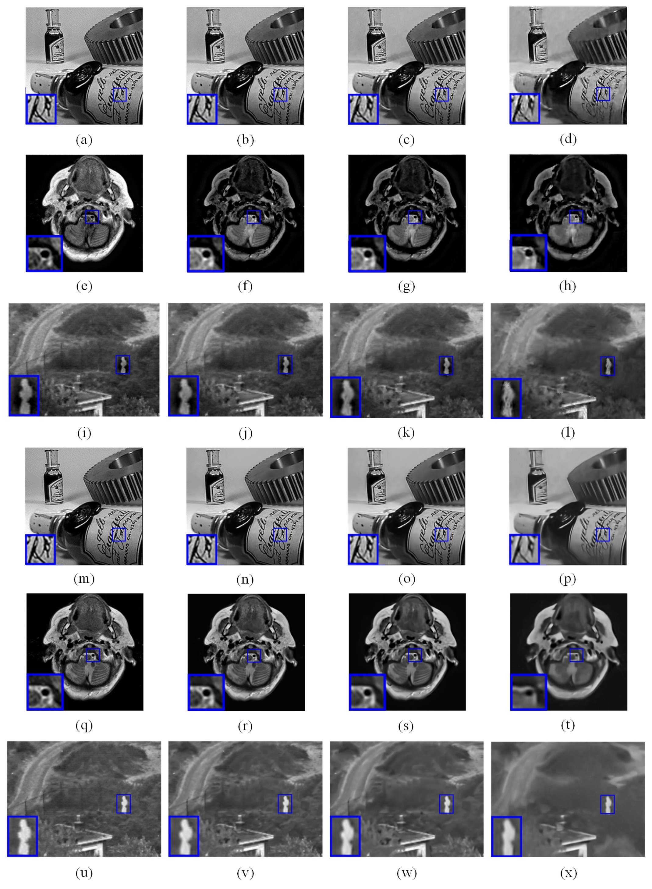
4.3.1. Comparison of Processing Results
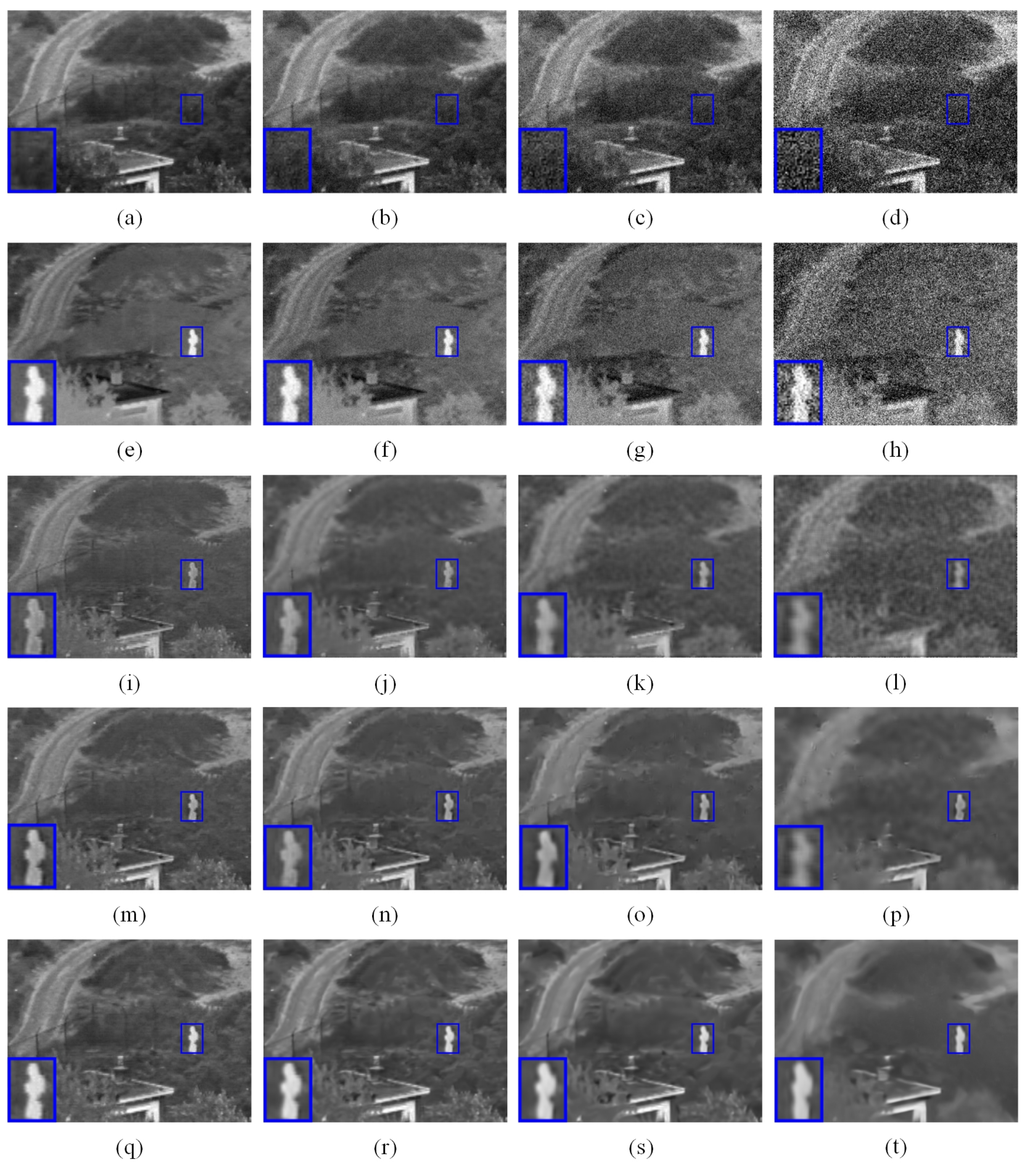
In comparative experiments, multi-focus, multi-modality medical and infrared-visible image pairs are employed. Noise is added to all source images for testing the processing performance. Noise levels of added noise are 0, 10, 20, and 50 respectively. The source images with noise level 0 are directly fused by conventional image fusion method in the comparative experiment. Representative fusion results are shown in Figure 10. Row 1 to 4 are the fused images with noise level from 0 to 50 respectively. The processing results of SDF is presented in image (a) to (l). Image (a)–(d), (e)–(h) and (i)–(l) are the processed results of multi-focus, multi-modality medical and infrared-visible image pairs respectively. (m)–(x) are the processed images by the proposed simultaneous image denoising and fusion method. Image (m) to (p), (q) to (t) and (u) to (x) are the processed results of multi-focus, multi-modality medical, and infrared-visible image pairs respectively.
According to the processed results shown in Figure 10, the proposed simultaneous image denoising and fusion method shows the best performance in brightness and contrast of the processed image. Parts of the processed images by SDF show the best performance in detailed information. However, since the denoising process affects the completeness of detailed information of source images, some detailed information of processed images is incomplete and unclear.
To evaluate the separate and simultaneous denoising and fusion performance, objective metrics are conducted. The results of multi-focus, multi-modality medical, and infrared-visible image denoising and fusion are shown in Table 11, Table 12 and Table 13 respectively. As shown in Table 11, the proposed method obtains better noisy multi-focus image denoising and fusion results in most of metrics. Table 12 also demonstrates the proposed method obtains a better score than the comparison method in most objective metrics. In noisy infrared-visible image denoising and fusion, SDF and fusion method obtain similar scores, when the noise level is low. Some metrics of separate processing results are even higher than the proposed method. However, as the noise level rises to 20 or higher, the proposed simultaneous processing method achieves obviously better performance in most of objective metrics.
Table 14, Table 15 and Table 16 compare the average objective evaluation results of each image type obtaind by SDF and the proposed method. The corresponding results are consistent with the results of the above demonstrated images. Compared with conventional image fusion and denoising method SDF, the proposed method has better performance in most of conditions.
4.3.2. Comparison of Computational Efficiency
Simultaneous image denoising and fusion can decrease the total processing time of noisy image fusion. The average processing times of separate and simultaneous image denoising and fusion are shown in Table 17. The processing times of SDF image denoising and fusion are demonstrated respectively. Since the proposed method processes image denoising and fusion simultaneously, it achieves the minimum total processing time as shown in Table 17.
The total computation cost of the proposed method is much lower than SDF. On average, the proposed method expends 21.73 s to process an image pair with the size of , that is more than 3 times faster than the competitor. For image pairs of , the proposed method also spends 3 times less computation time than SDF. Moreover, Table 17 shows the computation cost of proposed method is similar to the computation cost of the conventional image denoising or image fusion. In conclusion, compared with SDF, the proposed shows better performance in both processed image quality and computation cost.
5. Conclusions and Future Work
In this paper, a novel framework of image simultaneous denoising and fusion with a novel SR model is proposed. Noisy source images are decomposed into cartoon and texture components for separating image noise and detailed information to the texture components. To fuse the noisy texture components, a GSM-based image patch denoising and sparse coding model is presented for coding patches of noisy components to denoised sparse coefficients. Principle components of source noisy images are extracted to construct a dictionary, that is used to sparse code the texture components. Denoised and coded coefficients are fused by the value of hidden scalar multiplier . Since cartoon components are noise free, a conventional spatial-domain based weighted average rule is implemented. The weighted average fusion rule can greatly preserve the structure information, that is contained in cartoon components of source images. Integrated cartoon and texture components are summated to a denoised and fused image. The fusion results of the proposed method in various experiments is promising, when compared with other SR-based simultaneous denoising and fusion methods. Additionally, the computational efficiency of the proposed image fusion framework is comparable to SR-based simultaneous denoising and fusion methods with similar functions. Compared with image processed by SR-based denoising and fusing method separately, the proposed method also shows superior performance in both image quality and computation cost.
Although the proposed method gets better or comparable performance in computation costs compared with existing SR-based methods, the proposed method is still time consuming. Since there are plentiful matrix computations in sparse coding and dictionary learning, the processing time of SR-based method is a little bit long. The employment of a group-based sparse model for improving dictionary construction and parallel processing of both sparse representation and fusion process is a future research topic. Additionally, the proposed method will be further extended to the simultaneous denoising and fusion of colorful or multi-spectral images. The proposed method will be modified to process each image layer first. Then, the processed each image layer is stacked to obtain the denoised fusion result.
Author Contributions
Conceptualization, G.Q. and H.L.; methodology, G.Q., G.H. and N.M.; software, G.Q. and H.L.; validation, G.Q., G.H. and M.H.; formal analysis, G.Q. and G.H.; investigation, N.M.; resources, G.Q., G.H. and H.L.; data curation, H.L.; writing—original draft preparation, G.Q.; writing—review and editing, G.Q., G.H., N.M., H.L. and M.H.; visualization, H.L.; supervision, G.Q. and M.H.; project administration, G.H. All authors have read and agreed to the published version of the manuscript.
Funding
This research received no external funding.
Institutional Review Board Statement
Not applicable.
Informed Consent Statement
Not applicable.
Data Availability Statement
Not applicable.
Conflicts of Interest
The authors declare no conflict of interest.
Appendix A
| Algorithm A1 Cartoon Components Denoising and Fusion |
| Input: n noisy multi-modality images , the maximum iterative number k and j for outer loop and inner loop, respectively. Output: Fused image
|
References
- Zhang, J.; Hirakawa, K. Improved Denoising via Poisson Mixture Modeling of Image Sensor Noise. IEEE Trans. Image Process. 2017, 26, 1565–1579. [Google Scholar] [CrossRef]
- Zhu, Z.; Wei, H.; Hu, G.; Li, Y.; Qi, G.; Mazur, N. A Novel Fast Single Image Dehazing Algorithm Based on Artificial Multiexposure Image Fusion. IEEE Trans. Instrum. Meas. 2021, 70, 1–23. [Google Scholar]
- Zheng, M.; Qi, G.; Zhu, Z.; Li, Y.; Wei, H.; Liu, Y. Image Dehazing by an Artificial Image Fusion Method Based on Adaptive Structure Decomposition. IEEE Sens. J. 2020, 20, 8062–8072. [Google Scholar] [CrossRef]
- Li, H.; Li, X.; Yu, Z.; Mao, C. Multifocus image fusion by combining with mixed-order structure tensors and multiscale neighborhood. Inf. Sci. 2016, 349, 25–49. [Google Scholar] [CrossRef]
- Wang, K.; Zheng, M.; Wei, H.; Qi, G.; Li, Y. Multi-Modality Medical Image Fusion Using Convolutional Neural Network and Contrast Pyramid. Sensors 2020, 20, 2169. [Google Scholar] [CrossRef] [Green Version]
- Li, Y.; Sun, Y.; Huang, X.; Qi, G.; Zheng, M.; Zhu, Z. An Image Fusion Method Based on Sparse Representation and Sum Modified-Laplacian in NSCT Domain. Entropy 2018, 20, 522. [Google Scholar] [CrossRef] [Green Version]
- Li, S.; Kang, X.; Fang, L.; Hu, J.; Yin, H. Pixel-level image fusion: A survey of the state of the art. Inf. Fusion 2017, 33, 100–112. [Google Scholar] [CrossRef]
- Li, H.; Qiu, H.; Yu, Z.; Zhang, Y. Infrared and visible image fusion scheme based on NSCT and low-level visual features. Infrared Phys. Technol. 2016, 76, 174–184. [Google Scholar] [CrossRef]
- Zhu, Z.; Zheng, M.; Qi, G.; Wang, D.; Xiang, Y. A Phase Congruency and Local Laplacian Energy Based Multi-Modality Medical Image Fusion Method in NSCT Domain. IEEE Access 2019, 7, 20811–20824. [Google Scholar] [CrossRef]
- Li, S.; Yin, H.; Fang, L. Group-Sparse Representation With Dictionary Learning for Medical Image Denoising and Fusion. IEEE Trans. Biomed. Eng. 2012, 59, 3450–3459. [Google Scholar] [CrossRef] [PubMed]
- Zhu, Z.; Luo, Y.; Qi, G.; Meng, J.; Li, Y.; Mazur, N. Remote Sensing Image Defogging Networks Based on Dual Self-Attention Boost Residual Octave Convolution. Remote Sens. 2021, 13, 3104. [Google Scholar] [CrossRef]
- Zhu, Z.; Luo, Y.; Wei, H.; Li, Y.; Qi, G.; Mazur, N.; Li, Y.; Li, P. Atmospheric Light Estimation Based Remote Sensing Image Dehazing. Remote Sens. 2021, 13, 2432. [Google Scholar] [CrossRef]
- Jain, P.; Tyagi, V. LAPB: Locally adaptive patch-based wavelet domain edge-preserving image denoising. Inf. Sci. 2015, 294, 164–181. [Google Scholar] [CrossRef]
- Li, H.; Qiu, H.; Yu, Z.; Li, B. Multifocus image fusion via fixed window technique of multiscale images and non-local means filtering. Signal Process. 2017, 138, 71–85. [Google Scholar] [CrossRef]
- Li, H.; Liu, X.; Yu, Z.; Zhang, Y. Performance improvement scheme of multifocus image fusion derived by difference images. Signal Process. 2016, 128, 474–493. [Google Scholar] [CrossRef]
- Tropp, J.A. Greed is Good: Algorithmic Results for Sparse Approximation. IEEE Trans. Inf. Theory 2004, 50, 2231–2242. [Google Scholar] [CrossRef] [Green Version]
- Donoho, D.L.; Elad, M. Optimally sparse representation in general nonorthogonal dictionaries via l − 1 minimization. Proc. Natl. Acad. Sci. USA 2003, 100, 2197–2202. [Google Scholar] [CrossRef] [Green Version]
- Liu, H.; Liu, Y.; Sun, F. Robust Exemplar Extraction Using Structured Sparse Coding. IEEE Trans. Neural Netw. Learn. Syst. 2015, 26, 1816–1821. [Google Scholar] [CrossRef]
- Zhao, Y.Q.; Yang, J. Hyperspectral Image Denoising via Sparse Representation and Low-Rank Constraint. IEEE Trans. Geosci. Remote Sens. 2015, 53, 296–308. [Google Scholar] [CrossRef]
- Shekhar, S.; Patel, V.M.; Nasrabadi, N.M.; Chellappa, R. Joint Sparse Representation for Robust Multimodal Biometrics Recognition. IEEE Trans. Pattern Anal. Mach. Intell. 2014, 36, 113. [Google Scholar] [CrossRef]
- An, L.; Chen, X.; Yang, S.; Bhanu, B. Sparse representation matching for person re-identification. Inf. Sci. 2016, 355–356, 74–89. [Google Scholar] [CrossRef] [Green Version]
- Liu, H.; Guo, D.; Sun, F. Object Recognition Using Tactile Measurements: Kernel Sparse Coding Methods. IEEE Trans. Instrum. Meas. 2016, 65, 656–665. [Google Scholar] [CrossRef]
- Aharon, M.; Elad, M.; Bruckstein, A. K-SVD: An Algorithm for Designing Overcomplete Dictionaries for Sparse Representation. IEEE Trans. Signal Process. 2006, 54, 4311–4322. [Google Scholar] [CrossRef]
- Ophir, B.; Lustig, M.; Elad, M. Multi-Scale Dictionary Learning Using Wavelets. IEEE J. Sel. Top. Signal Process. 2011, 5, 1014–1024. [Google Scholar] [CrossRef]
- Mairal, J.; Bach, F.; Ponce, J.; Sapiro, G. Online dictionary learning for sparse coding. In Proceedings of the International Conference on Machine Learning, ICML 2009, Montreal, QC, Canada, 14–18 June 2009; pp. 689–696. [Google Scholar]
- Zoran, D.; Weiss, Y. From learning models of natural image patches to whole image restoration. In Proceedings of the International Conference on Computer Vision, Barcelona, Spain, 6–13 November 2011; pp. 479–486. [Google Scholar]
- Ji, S.; Xue, Y.; Carin, L. Bayesian Compressive Sensing. IEEE Trans. Signal Process. 2008, 56, 2346–2356. [Google Scholar] [CrossRef]
- Dong, W.; Shi, G.; Li, X. Nonlocal image restoration with bilateral variance estimation: A low-rank approach. IEEE Trans. Image Process. A Publ. IEEE Signal Process. Soc. 2013, 22, 700. [Google Scholar] [CrossRef]
- Liu, Y.; Liu, S.; Wang, Z. A general framework for image fusion based on multi-scale transform and sparse representation. Inf. Fusion 2015, 24, 147–164. [Google Scholar] [CrossRef]
- Yang, B.; Li, S. Multifocus Image Fusion and Restoration With Sparse Representation. IEEE Trans. Instrum. Meas. 2010, 59, 884–892. [Google Scholar] [CrossRef]
- Yin, M.; Duan, P.; Liu, W.; Liang, X. A novel infrared and visible image fusion algorithm based on shift-invariant dual-tree complex shearlet transform and sparse representation. Neurocomputing 2017, 226, 182–191. [Google Scholar] [CrossRef]
- Yin, H.; Li, Y.; Chai, Y.; Liu, Z.; Zhu, Z. A novel sparse-representation-based multi-focus image fusion approach. Neurocomputing 2016, 216, 216–229. [Google Scholar] [CrossRef]
- Zhu, Z.; Yin, H.; Chai, Y.; Li, Y.; Qi, G. A novel multi-modality image fusion method based on image decomposition and sparse representation. Inf. Sci. 2018, 432, 516–529. [Google Scholar] [CrossRef]
- Kim, M.; Han, D.K.; Ko, H. Joint patch clustering-based dictionary learning for multimodal image fusion. Inf. Fusion 2015, 27, 198–214. [Google Scholar] [CrossRef]
- Zhu, Z.; Qi, G.; Chai, Y.; Li, P. A Geometric Dictionary Learning Based Approach for Fluorescence Spectroscopy Image Fusion. Appl. Sci. 2017, 7, 161. [Google Scholar] [CrossRef]
- Wang, K.; Qi, G.; Zhu, Z.; Chai, Y. A Novel Geometric Dictionary Construction Approach for Sparse Representation Based Image Fusion. Entropy 2017, 19, 306. [Google Scholar] [CrossRef] [Green Version]
- Liu, Z.; Chai, Y.; Yin, H.; Zhou, J.; Zhu, Z. A novel multi-focus image fusion approach based on image decomposition. Inf. Fusion 2017, 35, 102–116. [Google Scholar] [CrossRef]
- Liu, Y.; Wang, Z. Simultaneous image fusion and denoising with adaptive sparse representation. Iet Image Process. 2015, 9, 347–357. [Google Scholar] [CrossRef] [Green Version]
- Li, H.; He, X.; Tao, D.; Tang, Y.; Wang, R. Joint medical image fusion, denoising and enhancement via discriminative low-rank sparse dictionaries learning. Pattern Recognit. 2018, 79, 130–146. [Google Scholar] [CrossRef]
- Li, X.; Zhou, F.; Tan, H. Joint image fusion and denoising via three-layer decomposition and sparse representation. Knowl.-Based Syst. 2021, 224, 107087. [Google Scholar] [CrossRef]
- Mei, J.J.; Dong, Y.; Huang, T.Z. Simultaneous image fusion and denoising by using fractional-order gradient information. J. Comput. Appl. Math. 2019, 351, 212–227. [Google Scholar] [CrossRef]
- Su, H.; Jung, C.; Yu, L. Multi-Spectral Fusion and Denoising of Color and Near-Infrared Images Using Multi-Scale Wavelet Analysis. Sensors 2021, 21, 3610. [Google Scholar] [CrossRef]
- Wang, W.; Zhang, C.; Ng, M.K. Variational model for simultaneously image denoising and contrast enhancement. Opt. Express 2020, 28, 18751–18777. [Google Scholar] [CrossRef]
- Yang, F.; Xu, S.; Li, C. Boosting of Denoising Effect with Fusion Strategy. Appl. Sci. 2020, 10, 3857. [Google Scholar] [CrossRef]
- Vese, L.A.; Osher, S. Image Denoising and Decomposition with Total Variation Minimization and Oscillatory Functions. J. Math. Imaging Vis. 2004, 20, 7–18. [Google Scholar] [CrossRef] [Green Version]
- Dong, W.; Shi, G.; Ma, Y.; Li, X. Image Restoration via Simultaneous Sparse Coding: Where Structured Sparsity Meets Gaussian Scale Mixture. Int. J. Comput. Vis. 2015, 114, 217–232. [Google Scholar] [CrossRef]
- Cvejic, N.; Canagarajah, C.N.; Bull, D.R. Image fusion metric based on mutual information and Tsallis entropy. Electron. Lett. 2006, 42, 626–627. [Google Scholar] [CrossRef]
- Liu, Z.; Blasch, E.; Xue, Z.; Zhao, J.; Laganiere, R.; Wu, W. Objective Assessment of Multiresolution Image Fusion Algorithms for Context Enhancement in Night Vision: A Comparative Study. IEEE Trans. Pattern Anal. Mach. Intell. 2011, 34, 94–109. [Google Scholar] [CrossRef] [PubMed]
- Wang, Q.; Shen, Y.; Jin, J. 19—Performance evaluation of image fusion techniques. Image Fusion 2008, 469–492. [Google Scholar] [CrossRef]
- Petrovic, V.S. Subjective tests for image fusion evaluation and objective metric validation. Inf. Fusion 2007, 8, 208–216. [Google Scholar] [CrossRef]
- Liu, Z.; Forsyth, D.S.; Laganière, R. A feature-based metric for the quantitative evaluation of pixel-level image fusion. Comput. Vis. Image Underst. 2008, 109, 56–68. [Google Scholar] [CrossRef]
- Wang, Q.; Shen, Y.; Zhang, Y.; Zhang, J.Q. Fast quantitative correlation analysis and information deviation analysis for evaluating the performances of image fusion techniques. IEEE Trans. Instrum. Meas. 2004, 53, 1441–1447. [Google Scholar] [CrossRef]
- Qi, G.; Chang, L.; Luo, Y.; Chen, Y.; Zhu, Z.; Wang, S. A Precise Multi-Exposure Image Fusion Method Based on Low-level Features. Sensors 2020, 20, 1597. [Google Scholar] [CrossRef] [PubMed] [Green Version]
- Yang, C.; Zhang, J.Q.; Wang, X.R.; Liu, X. A novel similarity based quality metric for image fusion. Inf. Fusion 2008, 9, 156–160. [Google Scholar] [CrossRef]
- Chen, Y.; Blum, R.S. A new automated quality assessment algorithm for image fusion. Image Vis. Comput. 2009, 27, 1421–1432. [Google Scholar] [CrossRef]
- Sheikh, H.R.; Bovik, A.C. Image information and visual quality. IEEE Trans. Image Process. 2006, 15, 430–444. [Google Scholar] [CrossRef]
- Huang, X.; Qi, G.; Wei, H.; Chai, Y.; Sim, J. A Novel Infrared and Visible Image Information Fusion Method Based on Phase Congruency and Image Entropy. Entropy 2019, 21, 1135. [Google Scholar] [CrossRef] [Green Version]
- Zuo, W.; Zhang, L.; Song, C.; Zhang, D.; Gao, H. Gradient Histogram Estimation and Preservation for Texture Enhanced Image Denoising. IEEE Trans. Image Process. A Publ. IEEE Signal Process. Soc. 2014, 23, 2459–2472. [Google Scholar]
Figure 1.
The Proposed Fusion Framework.

Figure 2.
The Proposed Fusion Framework. (a) a noisy image, (b) cartoon components, and (c) texture components.
Figure 2.
The Proposed Fusion Framework. (a) a noisy image, (b) cartoon components, and (c) texture components.

Figure 3.
Parts of Used Representative source images. (a–l) are selected source images.

Figure 4.
Simultaneous denoising and fusion results of noisy multi-focus image pairs -1. (a–h) are source multi-focus images with additional noise respectively; (i–t) are simultaneous denoising and fusion results of source images with additional noise by FDESD, FDS and proposed method respectively.
Figure 4.
Simultaneous denoising and fusion results of noisy multi-focus image pairs -1. (a–h) are source multi-focus images with additional noise respectively; (i–t) are simultaneous denoising and fusion results of source images with additional noise by FDESD, FDS and proposed method respectively.

Figure 5.
Simultaneous denoising and fusion results of noisy multi-focus image pairs -2. (a–h) are source multi-focus images with additional noise respectively; (i–t) are simultaneous denoising and fusion results of source images with additional noise by FDESD, FDS and proposed method respectively.
Figure 5.
Simultaneous denoising and fusion results of noisy multi-focus image pairs -2. (a–h) are source multi-focus images with additional noise respectively; (i–t) are simultaneous denoising and fusion results of source images with additional noise by FDESD, FDS and proposed method respectively.

Figure 6.
Simultaneous denoising and fusion results of FDESD, FDS and the proposed method for noisy multi-modality medical image pairs -1. (a–h) are source multi-modality medical images with additional noise respectively; (i–t) are simultaneous denoising and fusion results of source images with additional noise by FDESD, FDS and proposed method respectively.

Figure 7.
Simultaneous denoising and fusion results of FDESD, FDS and the proposed method for noisy multi-modality medical image pairs -2. (a–h) are source multi-modality medical images with additional noise respectively; (i–t) are simultaneous denoising and fusion results of source images with additional noise by FDESD, FDS and proposed method respectively.

Figure 8.
Simultaneous denoising and fusion results of FDESD, FDS and the proposed method for noisy infrared-visible image pairs. (a–h) are source infrared-visible images with additional noise respectively; (i–t) are simultaneous denoising and fusion results of source images with additional noise by FDESD, FDS and proposed method respectively.

Figure 9.
Simultaneous denoising and fusion results of FDESD, FDS and the proposed method for noisy infrared-visible image pairs -2. (a–h) are source infrared-visible images with additional noise respectively; (i–t) are simultaneous denoising and fusion results of source images with additional noise by FDESD, FDS and proposed method respectively.

Figure 10.
Comparison of separate and simultaneous image denoising and fusion results. (a–d) and (m–p) are denoising and fusion results of multi-focus image with additional noise by SDF and proposed method respectively. (e–h) and (q–t) are denoising and fusion results of malti-modality medical image with additional noise by SDF and proposed method respectively. (i–l) and (u–x) are denoising and fusion results of infrared-visible image with additional noise by SDF and proposed method respectively.


Table 1.
Objective evaluations of simultaneous multi-focus image denoising and fusion -1.
| VIFF | ||||||||
| FDESD | 0.6685 | 0.8160 | 0.7287 | 0.7539 | 1.7420 | 0.8963 | 0.6444 | 0.6257 |
| FDS | 0.7529 | 0.8190 | 0.7479 | 0.8387 | 1.9337 | 0.9248 | 0.7228 | 0.6770 |
| proposed | 0.9163 | 0.8251 | 0.7305 | 0.8499 | 2.3450 | 0.9657 | 0.7569 | 0.6962 |
| VIFF | ||||||||
| FDESD | 0.6056 | 0.8106 | 0.5614 | 0.5689 | 1.5623 | 0.7404 | 0.6132 | 0.6009 |
| FDS | 0.6446 | 0.8152 | 0.5745 | 0.6821 | 1.6617 | 0.7765 | 0.6745 | 0.6346 |
| proposed | 0.6527 | 0.8156 | 0.5857 | 0.6992 | 1.8871 | 0.7825 | 0.6804 | 0.6450 |
| VIFF | ||||||||
| FDESD | 0.5563 | 0.8122 | 0.4459 | 0.4078 | 1.4352 | 0.6336 | 0.5728 | 0.5549 |
| FDS | 0.6053 | 0.8140 | 0.4787 | 0.5188 | 1.5570 | 0.6713 | 0.6245 | 0.5578 |
| proposed | 0.6102 | 0.8142 | 0.4873 | 0.5538 | 1.5672 | 0.6933 | 0.6371 | 0.5777 |
| VIFF | ||||||||
| FDESD | 0.4511 | 0.8100 | 0.2633 | 0.1726 | 1.1615 | 0.4413 | 0.4928 | 0.4257 |
| FDS | 0.5369 | 0.8119 | 0.2619 | 0.2352 | 1.3656 | 0.4568 | 0.4696 | 0.4268 |
| proposed | 0.5472 | 0.8122 | 0.3014 | 0.3055 | 1.3852 | 0.5030 | 0.5276 | 0.4340 |
Table 2.
Objective evaluations of simultaneous multi-focus image denoising and fusion -2.
| VIFF | ||||||||
| FDESD | 0.6752 | 0.8098 | 0.7279 | 0.7692 | 1.7583 | 0.9034 | 0.6579 | 0.6372 |
| FDS | 0.7682 | 0.8197 | 0.7392 | 0.8393 | 1.9872 | 0.9244 | 0.7382 | 0.6804 |
| proposed | 0.9192 | 0.8317 | 0.7408 | 0.8503 | 2.3581 | 0.9694 | 0.7593 | 0.6985 |
| VIFF | ||||||||
| FDESD | 0.6193 | 0.8132 | 0.5687 | 0.5793 | 1.5736 | 0.7534 | 0.6328 | 0.6196 |
| FDS | 0.6487 | 0.8157 | 0.5783 | 0.6894 | 1.6689 | 0.7793 | 0.6784 | 0.6372 |
| proposed | 0.6576 | 0.8186 | 0.5873 | 0.6998 | 1.8903 | 0.7896 | 0.6864 | 0.6497 |
| VIFF | ||||||||
| FDESD | 0.5604 | 0.8146 | 0.4494 | 0.4184 | 1.4423 | 0.6406 | 0.5804 | 0.5569 |
| FDS | 0.6085 | 0.8195 | 0.4808 | 0.5268 | 1.5596 | 0.6792 | 0.6294 | 0.5608 |
| proposed | 0.6181 | 0.8237 | 0.4906 | 0.5587 | 1.5693 | 0.6987 | 0.6395 | 0.5788 |
| VIFF | ||||||||
| FDESD | 0.4595 | 0.8187 | 0.2693 | 0.1774 | 1.1709 | 0.4473 | 0.4989 | 0.4267 |
| FDS | 0.5409 | 0.8121 | 0.2746 | 0.2429 | 1.3726 | 0.4589 | 0.4785 | 0.4326 |
| proposed | 0.5503 | 0.8173 | 0.3068 | 0.3094 | 1.3873 | 0.5096 | 0.5316 | 0.4389 |
Table 3.
Average objective evaluations of simultaneous multi-focus image denoising and fusion.
| VIFF | ||||||||
| FDESD | 0.6749 | 0.8096 | 0.7277 | 0.7689 | 1.7580 | 0.9031 | 0.6576 | 0.6369 |
| FDS | 0.7678 | 0.8194 | 0.7388 | 0.8392 | 1.9867 | 0.9242 | 0.7380 | 0.6801 |
| proposed | 0.9187 | 0.8314 | 0.7404 | 0.8598 | 2.3579 | 0.9690 | 0.7590 | 0.6981 |
| VIFF | ||||||||
| FDESD | 0.6189 | 0.8127 | 0.5684 | 0.5789 | 1.5732 | 0.7531 | 0.6325 | 0.6192 |
| FDS | 0.6482 | 0.8153 | 0.5780 | 0.6889 | 1.6685 | 0.7790 | 0.6781 | 0.6369 |
| proposed | 0.6572 | 0.8183 | 0.5870 | 0.6994 | 1.8900 | 0.7893 | 0.6861 | 0.6493 |
| VIFF | ||||||||
| FDESD | 0.5601 | 0.8142 | 0.4490 | 0.4181 | 1.4421 | 0.6402 | 0.5899 | 0.5564 |
| FDS | 0.6081 | 0.8192 | 0.4803 | 0.5264 | 1.5592 | 0.6788 | 0.6291 | 0.5602 |
| proposed | 0.6177 | 0.8233 | 0.4902 | 0.5583 | 1.5689 | 0.6983 | 0.6391 | 0.5782 |
| VIFF | ||||||||
| FDESD | 0.4591 | 0.8182 | 0.2690 | 0.1772 | 1.1703 | 0.4470 | 0.4986 | 0.4264 |
| FDS | 0.5407 | 0.8118 | 0.2742 | 0.2426 | 1.3723 | 0.4584 | 0.4781 | 0.4323 |
| proposed | 0.5500 | 0.8171 | 0.3065 | 0.3092 | 1.3869 | 0.5094 | 0.5313 | 0.4386 |
Table 4.
Objective evaluations of simultaneous multi-modality medical image denoising and fusion -1.
Table 4.
Objective evaluations of simultaneous multi-modality medical image denoising and fusion -1.
| VIFF | ||||||||
| FDESD | 0.5571 | 0.8071 | 0.4010 | 0.4271 | 0.9989 | 0.4717 | 0.4252 | 0.3337 |
| FDS | 0.5677 | 0.8072 | 0.4837 | 0.5333 | 1.0068 | 0.5626 | 0.4686 | 0.3601 |
| proposed | 0.6537 | 0.8099 | 0.6583 | 0.5371 | 1.2223 | 0.7150 | 0.4698 | 0.4362 |
| VIFF | ||||||||
| FDESD | 0.4870 | 0.8064 | 0.3067 | 0.2584 | 0.9256 | 0.3998 | 0.3338 | 0.3075 |
| FDS | 0.5367 | 0.8069 | 0.3355 | 0.3852 | 0.9758 | 0.4635 | 0.3461 | 0.3167 |
| proposed | 0.5600 | 0.8077 | 0.4082 | 0.3938 | 1.0551 | 0.5408 | 0.3778 | 0.3729 |
| VIFF | ||||||||
| FDESD | 0.4331 | 0.8057 | 0.2661 | 0.1702 | 0.8386 | 0.3546 | 0.3349 | 0.2880 |
| FDS | 0.5099 | 0.8066 | 0.2815 | 0.2908 | 0.9459 | 0.3891 | 0.3245 | 0.2908 |
| proposed | 0.4871 | 0.8067 | 0.3221 | 0.2989 | 0.9477 | 0.4269 | 0.3594 | 0.3904 |
| VIFF | ||||||||
| FDESD | 0.2975 | 0.8041 | 0.1517 | 0.0663 | 0.5883 | 0.2200 | 0.2901 | 0.2360 |
| FDS | 0.4542 | 0.8058 | 0.1852 | 0.1548 | 0.8593 | 0.2744 | 0.2338 | 0.2402 |
| proposed | 0.4875 | 0.8064 | 0.2554 | 0.1903 | 0.9326 | 0.3472 | 0.2994 | 0.3013 |
Table 5.
Objective evaluations of simultaneous multi-modality medical image denoising and fusion -2.
Table 5.
Objective evaluations of simultaneous multi-modality medical image denoising and fusion -2.
| VIFF | ||||||||
| FDESD | 0.5582 | 0.8077 | 0.4047 | 0.4306 | 0.9997 | 0.4773 | 0.4302 | 0.3371 |
| FDS | 0.5691 | 0.8085 | 0.4869 | 0.5361 | 1.0103 | 0.5689 | 0.4690 | 0.3634 |
| proposed | 0.6575 | 0.8112 | 0.6599 | 0.5389 | 1.2286 | 0.7183 | 0.4708 | 0.4397 |
| VIFF | ||||||||
| FDESD | 0.4887 | 0.8077 | 0.3093 | 0.2604 | 0.9296 | 0.4063 | 0.3359 | 0.3096 |
| FDS | 0.5384 | 0.8098 | 0.3392 | 0.3887 | 0.9791 | 0.4663 | 0.3486 | 0.3191 |
| proposed | 0.5641 | 0.8103 | 0.4094 | 0.3974 | 1.0588 | 0.5437 | 0.3792 | 0.3764 |
| VIFF | ||||||||
| FDESD | 0.4362 | 0.8079 | 0.2686 | 0.1747 | 0.8406 | 0.3583 | 0.3385 | 0.2901 |
| FDS | 0.5102 | 0.8081 | 0.2855 | 0.2934 | 0.9481 | 0.3906 | 0.3273 | 0.2975 |
| proposed | 0.5132 | 0.8091 | 0.3234 | 0.2996 | 0.9497 | 0.4284 | 0.3606 | 0.3937 |
| VIFF | ||||||||
| FDESD | 0.2994 | 0.8080 | 0.1542 | 0.0676 | 0.5897 | 0.2221 | 0.2932 | 0.2393 |
| FDS | 0.4576 | 0.8087 | 0.1891 | 0.1586 | 0.8612 | 0.2786 | 0.2367 | 0.2435 |
| proposed | 0.4902 | 0.8093 | 0.2577 | 0.1938 | 0.9361 | 0.3496 | 0.3008 | 0.3037 |
Table 6.
Average objective evaluations of simultaneous multi-modality medical image denoising and fusion.
Table 6.
Average objective evaluations of simultaneous multi-modality medical image denoising and fusion.
| VIFF | ||||||||
| FDESD | 0.5580 | 0.8075 | 0.4043 | 0.4302 | 0.9994 | 0.4771 | 0.4300 | 0.3369 |
| FDS | 0.5688 | 0.8082 | 0.4866 | 0.5357 | 1.0101 | 0.5685 | 0.4686 | 0.3631 |
| proposed | 0.6572 | 0.8108 | 0.6595 | 0.5386 | 1.2282 | 0.7180 | 0.4702 | 0.4393 |
| VIFF | ||||||||
| FDESD | 0.4883 | 0.8074 | 0.3090 | 0.2601 | 0.9293 | 0.4059 | 0.3355 | 0.3092 |
| FDS | 0.5381 | 0.8095 | 0.3388 | 0.3882 | 0.9787 | 0.4660 | 0.3482 | 0.3187 |
| proposed | 0.5635 | 0.8100 | 0.4091 | 0.3971 | 1.0585 | 0.5433 | 0.3786 | 0.3761 |
| VIFF | ||||||||
| FDESD | 0.4359 | 0.8076 | 0.2684 | 0.1744 | 0.8404 | 0.3581 | 0.3382 | 0.2987 |
| FDS | 0.5198 | 0.8077 | 0.2851 | 0.2932 | 0.9476 | 0.3902 | 0.3270 | 0.2971 |
| proposed | 0.5129 | 0.8087 | 0.3231 | 0.2992 | 0.9493 | 0.4281 | 0.3602 | 0.3933 |
| VIFF | ||||||||
| FDESD | 0.2991 | 0.8078 | 0.1538 | 0.0672 | 0.5893 | 0.2217 | 0.2928 | 0.2390 |
| FDS | 0.4572 | 0.8083 | 0.1887 | 0.1582 | 0.8607 | 0.2782 | 0.2362 | 0.2431 |
| proposed | 0.4897 | 0.8090 | 0.2572 | 0.1934 | 0.9358 | 0.3492 | 0.3005 | 0.3033 |
Table 7.
Objective evaluations of simultaneous infrared-visible image denoising and fusion -1.
| VIFF | ||||||||
| FDESD | 0.2891 | 0.8040 | 0.5818 | 0.3201 | 0.6301 | 0.6924 | 0.4884 | 0.2814 |
| FDS | 0.2989 | 0.8043 | 0.6229 | 0.4378 | 0.6638 | 0.7774 | 0.5425 | 0.3122 |
| proposed | 0.3582 | 0.8059 | 0.6543 | 0.5000 | 0.8173 | 0.8785 | 0.5434 | 0.3975 |
| VIFF | ||||||||
| FDESD | 0.2949 | 0.8041 | 0.3473 | 0.1734 | 0.6460 | 0.4862 | 0.4878 | 0.2870 |
| FDS | 0.2948 | 0.8041 | 0.4259 | 0.2773 | 0.6531 | 0.5748 | 0.5085 | 0.3011 |
| proposed | 0.3185 | 0.8048 | 0.4514 | 0.3049 | 0.7232 | 0.6580 | 0.5111 | 0.3727 |
| VIFF | ||||||||
| FDESD | 0.2808 | 0.8031 | 0.3204 | 0.1188 | 0.6253 | 0.4873 | 0.4561 | 0.2835 |
| FDS | 0.2928 | 0.8031 | 0.3314 | 0.2081 | 0.6455 | 0.4660 | 0.4624 | 0.2706 |
| proposed | 0.3217 | 0.8050 | 0.3862 | 0.2355 | 0.7309 | 0.5704 | 0.4641 | 0.3429 |
| VIFF | ||||||||
| FDESD | 0.2114 | 0.8031 | 0.2259 | 0.0534 | 0.4697 | 0.3914 | 0.4380 | 0.2038 |
| FDS | 0.2606 | 0.8035 | 0.1894 | 0.1079 | 0.5614 | 0.3176 | 0.3946 | 0.2065 |
| proposed | 0.2933 | 0.8041 | 0.2378 | 0.1324 | 0.6522 | 0.3856 | 0.3771 | 0.2356 |
Table 8.
Objective evaluations of simultaneous infrared-visible image denoising and fusion -2.
| VIFF | ||||||||
| FDESD | 0.2906 | 0.8043 | 0.5843 | 0.3236 | 0.6341 | 0.6952 | 0.4897 | 0.2846 |
| FDS | 0.3006 | 0.8049 | 0.6251 | 0.4398 | 0.6658 | 0.7793 | 0.5449 | 0.3141 |
| proposed | 0.3593 | 0.8063 | 0.6561 | 0.5011 | 0.8189 | 0.8793 | 0.5452 | 0.3996 |
| VIFF | ||||||||
| FDESD | 0.2961 | 0.8051 | 0.3488 | 0.1749 | 0.6473 | 0.4881 | 0.4890 | 0.2887 |
| FDS | 0.2964 | 0.8059 | 0.4268 | 0.2782 | 0.6562 | 0.5767 | 0.5097 | 0.3038 |
| proposed | 0.3194 | 0.8062 | 0.4539 | 0.3077 | 0.7261 | 0.6595 | 0.5133 | 0.3752 |
| VIFF | ||||||||
| FDESD | 0.2821 | 0.8052 | 0.3228 | 0.1201 | 0.6275 | 0.4888 | 0.4579 | 0.2851 |
| FDS | 0.2942 | 0.8050 | 0.3336 | 0.2101 | 0.6473 | 0.4687 | 0.4653 | 0.2728 |
| proposed | 0.3234 | 0.8068 | 0.3879 | 0.2371 | 0.7327 | 0.5721 | 0.4663 | 0.3447 |
| VIFF | ||||||||
| FDESD | 0.2135 | 0.8049 | 0.2280 | 0.0553 | 0.4707 | 0.3946 | 0.4399 | 0.2060 |
| FDS | 0.2631 | 0.8051 | 0.1910 | 0.1097 | 0.5633 | 0.3196 | 0.3971 | 0.2082 |
| proposed | 0.2946 | 0.8056 | 0.2391 | 0.1340 | 0.6537 | 0.3872 | 0.3787 | 0.2369 |
Table 9.
Average objective evaluations of simultaneous infrared-visible image denoising and fusion.
| VIFF | ||||||||
| FDESD | 0.2903 | 0.8041 | 0.5840 | 0.3234 | 0.6340 | 0.6959 | 0.4892 | 0.2842 |
| FDS | 0.3003 | 0.8045 | 0.6247 | 0.4395 | 0.6654 | 0.7790 | 0.5445 | 0.3137 |
| proposed | 0.3590 | 0.8059 | 0.6558 | 0.5008 | 0.8185 | 0.8790 | 0.5448 | 0.3991 |
| VIFF | ||||||||
| FDESD | 0.2957 | 0.8048 | 0.3483 | 0.1745 | 0.6471 | 0.4877 | 0.4886 | 0.2884 |
| FDS | 0.2961 | 0.8054 | 0.4266 | 0.2777 | 0.6557 | 0.5763 | 0.5092 | 0.3034 |
| proposed | 0.3191 | 0.8057 | 0.4535 | 0.3074 | 0.7256 | 0.6591 | 0.5130 | 0.3748 |
| VIFF | ||||||||
| FDESD | 0.2818 | 0.8047 | 0.3223 | 0.1197 | 0.6272 | 0.4885 | 0.4577 | 0.2848 |
| FDS | 0.2940 | 0.8046 | 0.3332 | 0.2096 | 0.6470 | 0.4681 | 0.4650 | 0.2722 |
| proposed | 0.3231 | 0.8062 | 0.3877 | 0.2366 | 0.7323 | 0.5717 | 0.4659 | 0.3444 |
| VIFF | ||||||||
| FDESD | 0.2131 | 0.8043 | 0.2275 | 0.0548 | 0.4702 | 0.3943 | 0.4395 | 0.2057 |
| FDS | 0.2627 | 0.8047 | 0.1905 | 0.1093 | 0.5630 | 0.3192 | 0.3966 | 0.2078 |
| proposed | 0.2942 | 0.8053 | 0.2386 | 0.1335 | 0.6533 | 0.3868 | 0.3785 | 0.235 |
Table 10.
The Average Computational Efficiency Comparison of Noisy Image Fusion.
| Resolution | ||
|---|---|---|
| FDESD | 36.82 s | 46.53 s |
| FDS | 20.71 s | 24.56 s |
| Proposed | 21.55 s | 26.71 s |
Table 11.
Objective evaluations of separate and simultaneous noisy-multi-focus image denoising and fusion.
Table 11.
Objective evaluations of separate and simultaneous noisy-multi-focus image denoising and fusion.
| VIFF | ||||||||
| SDF | 0.7158 | 0.8189 | 0.6975 | 0.8337 | 1.9508 | 0.8560 | 0.7154 | 0.6665 |
| proposed | 0.9163 | 0.8251 | 0.7305 | 0.8499 | 2.3450 | 0.9657 | 0.7569 | 0.6962 |
| VIFF | ||||||||
| SDF | 0.6650 | 0.8171 | 0.4871 | 0.6259 | 1.7849 | 0.7047 | 0.6647 | 0.6326 |
| proposed | 0.6527 | 0.8156 | 0.5857 | 0.6992 | 1.8871 | 0.7825 | 0.6804 | 0.6450 |
| VIFF | ||||||||
| SDF | 0.6045 | 0.8134 | 0.3771 | 0.5575 | 1.6920 | 0.6060 | 0.6361 | 0.5696 |
| proposed | 0.6102 | 0.8142 | 0.4873 | 0.5538 | 1.5672 | 0.6933 | 0.6371 | 0.5777 |
| VIFF | ||||||||
| SDF | 0.5183 | 0.8150 | 0.2662 | 0.3792 | 1.2276 | 0.4690 | 0.4570 | 0.4154 |
| proposed | 0.5472 | 0.8122 | 0.3014 | 0.3055 | 1.3852 | 0.5030 | 0.5276 | 0.4340 |
Table 12.
Objective evaluations of separate and simultaneous noisy-multi-modality medical image denoising and fusion.
Table 12.
Objective evaluations of separate and simultaneous noisy-multi-modality medical image denoising and fusion.
| VIFF | ||||||||
| SDF | 0.6438 | 0.8092 | 0.4780 | 0.4423 | 1.2116 | 0.7236 | 0.5301 | 0.4440 |
| proposed | 0.6537 | 0.8099 | 0.6583 | 0.5371 | 1.2223 | 0.7150 | 0.4698 | 0.4362 |
| VIFF | ||||||||
| SDF | 0.4505 | 0.8055 | 0.2155 | 0.2314 | 0.7749 | 0.3289 | 0.4240 | 0.2797 |
| proposed | 0.5600 | 0.8077 | 0.4082 | 0.3938 | 1.0551 | 0.5408 | 0.3778 | 0.3729 |
| VIFF | ||||||||
| SDF | 0.4530 | 0.8055 | 0.1845 | 0.1833 | 0.7530 | 0.3245 | 0.3710 | 0.2725 |
| proposed | 0.4871 | 0.8067 | 0.3221 | 0.2689 | 0.9477 | 0.4269 | 0.3594 | 0.3904 |
| VIFF | ||||||||
| SDF | 0.4443 | 0.8055 | 0.1348 | 0.1240 | 0.7440 | 0.2724 | 0.3188 | 0.2510 |
| proposed | 0.4875 | 0.8064 | 0.2554 | 0.1903 | 0.9326 | 0.3472 | 0.2994 | 0.3013 |
Table 13.
Objective evaluations of separate and simultaneous noisy-infrared-visible image denoising and fusion.
Table 13.
Objective evaluations of separate and simultaneous noisy-infrared-visible image denoising and fusion.
| VIFF | ||||||||
| SDF | 0.3867 | 0.8070 | 0.6435 | 0.5897 | 0.7985 | 0.7908 | 0.4808 | 0.3042 |
| proposed | 0.3582 | 0.8059 | 0.6543 | 0.5000 | 0.8173 | 0.8785 | 0.5434 | 0.3975 |
| VIFF | ||||||||
| SDF | 0.3383 | 0.8064 | 0.4510 | 0.2406 | 0.7029 | 0.6174 | 0.5279 | 0.2820 |
| proposed | 0.3185 | 0.8048 | 0.4514 | 0.3049 | 0.7232 | 0.6580 | 0.5111 | 0.3727 |
| VIFF | ||||||||
| SDF | 0.3095 | 0.8051 | 0.3602 | 0.1283 | 0.6554 | 0.5401 | 0.4515 | 0.2540 |
| proposed | 0.3217 | 0.8050 | 0.3862 | 0.2355 | 0.7309 | 0.5704 | 0.4641 | 0.3429 |
| VIFF | ||||||||
| SDF | 0.2744 | 0.8054 | 0.2235 | 0.0909 | 0.6228 | 0.3038 | 0.3233 | 0.1893 |
| proposed | 0.2933 | 0.8041 | 0.2378 | 0.1324 | 0.6522 | 0.3856 | 0.3771 | 0.2356 |
Table 14.
Average objective evaluations of separate and simultaneous noisy-multi-focus image denoising and fusion.
Table 14.
Average objective evaluations of separate and simultaneous noisy-multi-focus image denoising and fusion.
| VIFF | ||||||||
| SDF | 0.7165 | 0.8194 | 0.6979 | 0.8343 | 1.9513 | 0.8564 | 0.7159 | 0.6668 |
| proposed | 0.9166 | 0.8255 | 0.7308 | 0.8503 | 2.3454 | 0.9662 | 0.7574 | 0.6968 |
| VIFF | ||||||||
| SDF | 0.6655 | 0.8174 | 0.4876 | 0.6265 | 1.7855 | 0.7050 | 0.6653 | 0.6330 |
| proposed | 0.6532 | 0.8160 | 0.5863 | 0.6999 | 1.8877 | 0.7829 | 0.6808 | 0.6455 |
| VIFF | ||||||||
| SDF | 0.6048 | 0.8138 | 0.3776 | 0.5579 | 1.6924 | 0.6063 | 0.6367 | 0.5699 |
| proposed | 0.6106 | 0.8149 | 0.4878 | 0.5542 | 1.5677 | 0.6938 | 0.6375 | 0.5782 |
| VIFF | ||||||||
| SDF | 0.5188 | 0.8155 | 0.2668 | 0.3798 | 1.2281 | 0.4696 | 0.4575 | 0.4159 |
| proposed | 0.5477 | 0.8125 | 0.3018 | 0.3059 | 1.3857 | 0.5035 | 0.5280 | 0.4346 |
Table 15.
Average objective evaluations of separate and simultaneous noisy-multi-modality medical image denoising and fusion.
Table 15.
Average objective evaluations of separate and simultaneous noisy-multi-modality medical image denoising and fusion.
| VIFF | ||||||||
| SDF | 0.6443 | 0.8098 | 0.4787 | 0.4428 | 1.2120 | 0.7242 | 0.5307 | 0.4448 |
| proposed | 0.6546 | 0.8105 | 0.6589 | 0.5378 | 1.2227 | 0.7155 | 0.4704 | 0.4370 |
| VIFF | ||||||||
| SDF | 0.4511 | 0.8062 | 0.2164 | 0.2319 | 0.7753 | 0.3294 | 0.4248 | 0.2804 |
| proposed | 0.5606 | 0.8083 | 0.4087 | 0.3945 | 1.0558 | 0.5415 | 0.3784 | 0.3735 |
| VIFF | ||||||||
| SDF | 0.4534 | 0.8061 | 0.1852 | 0.1838 | 0.7536 | 0.3249 | 0.3716 | 0.2731 |
| proposed | 0.4876 | 0.8072 | 0.3226 | 0.2696 | 0.9484 | 0.4275 | 0.3599 | 0.3911 |
| VIFF | ||||||||
| SDF | 0.4448 | 0.8062 | 0.1354 | 0.1248 | 0.7447 | 0.2729 | 0.3193 | 0.2517 |
| proposed | 0.4879 | 0.8068 | 0.2560 | 0.1908 | 0.9333 | 0.3478 | 0.3001 | 0.3019 |
Table 16.
Average objective evaluations of separate and simultaneous noisy-infrared-visible image denoising and fusion.
Table 16.
Average objective evaluations of separate and simultaneous noisy-infrared-visible image denoising and fusion.
| VIFF | ||||||||
| SDF | 0.3873 | 0.8076 | 0.6440 | 0.5905 | 0.7992 | 0.7914 | 0.4813 | 0.3048 |
| proposed | 0.3590 | 0.8064 | 0.6547 | 0.5006 | 0.8176 | 0.8791 | 0.5439 | 0.3978 |
| VIFF | ||||||||
| SDF | 0.3389 | 0.8067 | 0.4515 | 0.2412 | 0.7036 | 0.6179 | 0.5286 | 0.2827 |
| proposed | 0.3189 | 0.8054 | 0.4519 | 0.3056 | 0.7239 | 0.6586 | 0.5119 | 0.3735 |
| VIFF | ||||||||
| SDF | 0.3102 | 0.8058 | 0.3608 | 0.1289 | 0.6562 | 0.5409 | 0.4522 | 0.2546 |
| proposed | 0.3223 | 0.8057 | 0.3868 | 0.2362 | 0.7317 | 0.5710 | 0.4648 | 0.3434 |
| VIFF | ||||||||
| SDF | 0.2750 | 0.8059 | 0.2241 | 0.0916 | 0.6234 | 0.3045 | 0.3238 | 0.1899 |
| proposed | 0.2938 | 0.8046 | 0.2383 | 0.1328 | 0.6529 | 0.3860 | 0.3778 | 0.2363 |
Table 17.
Comparison of Average Computational Efficiency.
| Noisy Image Fusion Computational Efficiency of Images | |||
| Processing Time of SDF | Total Processing Time of Proposed Method | ||
| Image Denoising and Fusion | |||
| Denoising | Fusion | Total | |
| 41.77 s | 28.61 s | 70.38 s | 21.73 s |
| Noisy Image Fusion Computational Efficiency of Images | |||
| Processing Time of SDF | Total Processing Time of Proposed Method | ||
| Image Denoising and Fusion | |||
| Denoising | Fusion | Total | |
| 48.72 s | 34.69 s | 83.41 s | 26.83 s |
Publisher’s Note: MDPI stays neutral with regard to jurisdictional claims in published maps and institutional affiliations. |
© 2021 by the authors. Licensee MDPI, Basel, Switzerland. This article is an open access article distributed under the terms and conditions of the Creative Commons Attribution (CC BY) license (https://creativecommons.org/licenses/by/4.0/).
Share and Cite
MDPI and ACS Style
Qi, G.; Hu, G.; Mazur, N.; Liang, H.; Haner, M. A Novel Multi-Modality Image Simultaneous Denoising and Fusion Method Based on Sparse Representation. Computers 2021, 10, 129. https://0-doi-org.brum.beds.ac.uk/10.3390/computers10100129
AMA Style
Qi G, Hu G, Mazur N, Liang H, Haner M. A Novel Multi-Modality Image Simultaneous Denoising and Fusion Method Based on Sparse Representation. Computers. 2021; 10(10):129. https://0-doi-org.brum.beds.ac.uk/10.3390/computers10100129
Chicago/Turabian StyleQi, Guanqiu, Gang Hu, Neal Mazur, Huahua Liang, and Matthew Haner. 2021. "A Novel Multi-Modality Image Simultaneous Denoising and Fusion Method Based on Sparse Representation" Computers 10, no. 10: 129. https://0-doi-org.brum.beds.ac.uk/10.3390/computers10100129
Note that from the first issue of 2016, this journal uses article numbers instead of page numbers. See further details here.