
Colocation for SLAM-Tracked VR Headsets with Hand Tracking


1
Faculty for Electrical Engineering and Computer Science, Ravensburg-Weingarten University, 88250 Weingarten, Germany
2
Institute of Visual Computing and Human-Centered Technology, TU Wien, 1040 Vienna, Austria
*
Author to whom correspondence should be addressed.
Computers 2021, 10(5), 58; https://0-doi-org.brum.beds.ac.uk/10.3390/computers10050058
Submission received: 30 March 2021
/
Revised: 19 April 2021
/
Accepted: 22 April 2021
/
Published: 27 April 2021
(This article belongs to the Special Issue Advances in Seated Virtual Reality)
Abstract
:In colocated multi-user Virtual Reality applications, relative user positions in the virtual environment need to match their relative positions in the physical tracking space. A mismatch between virtual and real relative user positions might lead to harmful events such as physical user collisions. This paper examines three calibration methods that enable colocated Virtual Reality scenarios for SLAM-tracked head-mounted displays without the need for an external tracking system. Two of these methods—fixed-point calibration and marked-based calibration—have been described in previous research; the third method that uses hand tracking capabilities of head-mounted displays is novel. We evaluated the accuracy of these three methods in an experimental procedure with two colocated Oculus Quest devices. The results of the evaluation show that our novel hand tracking-based calibration method provides better accuracy and consistency while at the same time being easy to execute. The paper further discusses the potential of all evaluated calibration methods.
1. Introduction
Numerous Virtual Reality (VR) applications exploit multi-user experiences, such as multi-player games in VR (Available online: https://www.tetrastudios.com.au/ (accessed on 31 January 2021)), virtual meeting environments emphasizing social interactions (Available online: https://spatial.io/ (accessed on 31 January 2021)) or casual VR chat platforms (Available online: https://hello.vrchat.com/ (accessed on 31 January 2021)). Even in the area of facility management, a multi-user shared virtual environment can be used to improve the efficiency of communication [1]. Multi-user VR experiences can take place in a number of physical setups. Podkosova created a taxonomy of different multi-user scenarios that are categorized with respect to varying combinations of sharing of virtual and physical spaces [2]. Setups in which users share the physical and the virtual space simultaneously are defined as colocated shared VR. Such colocated VR scenarios can be used in walkable arena-scaled environments (e.g., games or exploratory VR scenarios [1]). They can also be used in seated VR scenarios, where users typically do not navigate extensively but still need to be aware of the positions of other users in the same virtual (and physical) environment.
In a functioning colocated VR application, poses of all users within the same coordinate frame need to be known. Often, this coordinate frame is associated with the shared physical environment itself. For example, Podkosova et al. used a multi-marker tracking technique which assigned the common coordinate frame to one of the markers placed within the tracking space [3]. Other systems like OptiTrack offer camera systems for large physical environments to track each user inside the shared space [4]. These solutions always need external cameras and a complicated setup to implement a colocated shared VR experience.
Currently, head-mounted displays (HMDs) that use in-built visual SLAM techniques for head tracking are gaining popularity in the consumer VR market. SLAM-tracked HMDs demonstrate a substantial advantage of not requiring an external camera setup for fast and precise 6-DOF tracking, often in environments that are larger than those that similarly-priced external tracking camera installations can cover. Tracking algorithms based on visual SLAM map the environment while simultaneously calculating the pose of the HMD within the map that is being created [5]. Oculus Quest is an example of a SLAM-enabled HMD available to consumers. Compared to other popular VR headsets, the Oculus Quest is independent of external hardware such as tracking cameras. Being a standalone Android-running computer, it provides an entirely untethered experience. As a SLAM-tracked device, each Oculus Quest creates an individual tracking map that cannot be read out and copied to other devices. This fact makes creating a shared colocated VR experience a challenging task.
In this paper, we address this challenge by investigating three methods that calibrate SLAM-tracked HMDs used within the same physical environment to create a shared colocated VR scenario:
- Fixed-point calibration, for which all colocated HMDs are placed at predefined positions within the physical environment.
- Marker-based calibration, for which a marker placed in the physical environment needs to be tracked simultaneously by all client applications running on users’ HMDs.
- Hand tracking-based calibration, in which the hands of one of the colocated users are used as spatial anchors simultaneously tracked by all client applications.
While two of the investigated calibration methods—fixed-point calibration and marker-based calibration—have been used in previous research, the hand tracking-based calibration method is completely novel. The accuracy of all calibration methods is assessed in an experimental evaluation presented in the paper, with an extensive discussion of each method’s performance and applicability.
To summarize, this paper presents the following contributions:
- A new calibration method for shared colocated VR scenarios using SLAM-tracked HMDs with hand tracking. Our method uses user hands as spatial calibration anchors and therefore does not require any additional infrastructure. The method shows superior calibration accuracy.
- An experimental evaluation of the accuracy of three colocation calibration methods.
- Analysis of limitations and future possibilities of the discussed calibration methods.
The remainder of the paper is structured as follows: Section 2 discusses previously published research on colocation with SLAM tracked VR headsets and hand tracking, which is the basis of our novel method. Section 3 presents the design and implementation details of the investigated calibration methods. Section 4 follows with the presentation of our evaluation experiment and its results, which are further discussed in detail in Section 5. Section 6 concludes the paper.
2. Related Work
Colocated multi-user experiences allow users to share the same virtual and physical space with their mixed-reality devices. The areas of application are diverse. Business applications use this for example for virtual meetings and presentations [6]. In gaming scenarios, users can play the same game in the same room (Available online: https://arena.vrlab.com/ (accessed on 12 March 2021)).
2.1. Colocation for SLAM Tracked Headsets
VR HMDs use different tracking technologies. In many systems, external cameras to track the user inside the physical room are used (e.g., the HTC VIVE with its Lighthouse system [7]). Other VR HMDs use integrated cameras and sensors to determine their pose inside a simultaneously mapped environment (e.g., the Oculus Quest (Available online: https://medium.com/@kenwang_57215/oculus-solution-to-room-scale-vr-37b2ff654dc9 (accessed on 15 January 2021)). This latter technology has the advantage that the calibration does not need a predefined camera setup and is not limited to the external cameras’ field of view. However, this is also why every SLAM tracked headset has its distinct internal environment mapping. The headsets do not share this data with other devices. Contrary to that, all VR headsets inside an external camera setup share the same mapping, making a colocation much easier.
Some researchers already found some solutions to solve this problem with colocation for virtual and mixed reality headsets. McGill et al. divided some solutions into two categories: “Aligning to a single known point” and “Aligning to two known points” [8].
The alignment to a single known point is easy to use. The idea is that we have a single point in the real world and a reference point in the virtual world. When knowing where our headset location is relative to the real point, we can set the user’s virtual pose with the same relativity to the virtual point. An example of such a setup would be the CAVE experience by Layng et al., where every user is assigned a seat with a predetermined position analogically represented in the real world [9]. The VR game Triton VR (Available online: https://www.tetrastudios.com.au/ (accessed on 31 January 2021)) lets the users stand in the same physical location to colocate multiple users. Their location is then recalibrated inside the virtual environment to fit their real-world pose. The precision of this method is dependent on how accurate the users stand on the predefined position.
On the other hand, a two-point calibration uses two points or anchors in the real world to better approximate the users’ pose, which also reduces drifting in larger rooms [8]. Since this calibration needs multiple calibration points, the setup also takes longer than in the one-point calibration. This is why we focused on one-point calibration methods in this setup since we use our methods in a standard room-sized environment.
Colocation can also be achieved by tracking a marker with the headset. DeFanti proposed a solution where multiple users inside a colocated space track each other with a camera on their HMD to track ArUco markers attached to each user. This data are then shared with each user to recalculate the relative positions to each other in the virtual world [10]. This method requires the correct recognition of each other’s markers to be always present and precise.
All these solutions require either additional hardware as AR-tracking cameras and markers or are dependent on positioning in the real world and the user’s precision.
As more and more SLAM tracked VR-headsets are developed, which also offer integrated hand tracking (e.g., Oculus Quest, or VIVE Focus (Available online: https://enterprise.vive.com/de/product/vive-focus/ (accessed on 10 February 2021)), we will show a solution to use this feature for colocation. That way, the precision is not dependent on the user but depends on the tracking system. Additionally, one does not require additional hardware, but only the SLAM tracked headsets.
We can also differ between a continuous colocation and a one-time colocation. When external cameras are used to track the user, each user’s location is updated every frame for the tracking systems coordinate system allowing to adjust the user’s alignment every frame. Weissker et al. did such a colocation using the Lighthouse tracking system of the HTC Vive [11]. DeFanti used cameras attached to the users’ HMD to track the other user continuously [10]. Furthermore, Podkosova et al. created ImmersiveDeck, a system where an inside-out head tracking is used together with motion capture to allow multiple users to move freely in a large area (i.e., 200 m2) [3]. In addition, in robotics, a shared spatial map can be used to have a shared application where they can, for example, maximize their efficiency in environment exploration [12]. Contrary to that, a one-time calibration aligns all devices only once. For the time after calibration, the accuracy is dependent on the tracking accuracy of the device. If the error gets too big, a recalibration has to be done. McGill et al., for example, used such one-time calibrations in their experiments, be it for a one- or two-point calibration [8]. Alternatively, in seated experiences such as CAVE or CAVRN, users are positioned on a real-world seat, which corresponds to a virtual orientation, and position [9,13]. A continuous colocation is not done during the experience. Since we want to keep additional hardware and efforts as low as possible, our approach uses one-time calibration to rely on our SLAM device’s low drift after calibration. A recalibration should nonetheless be possible without much effort.
Altogether, the three used calibration methods could be categorized as a one-time one-point calibration method for colocation.
2.2. Hand Tracking for VR
To track and virtualize the hand of a user is researched for some years. In 1986, the company “VPL Research” developed the first commercial glove to obtain hand tracking. With the help of glass fiber, they could detect the curvature of the finger [14]. Other commercial data gloves followed this development (e.g., the CyberGlove [15] or other low-cost glove for VR [16]) or tried to improve the tracking [17].
This kind of hand tracking always requires a fabric that has to be worn by the user. Alternatively, there currently exist tracking systems that optically track the hands and knuckles of the user with the help of cameras (like Hammer et al. who are using an RGB camera [18]) and sensors (like the LeapMotion controller, which uses infra-red cameras and emitters [19]) without needing additional gloves. Devices like the LeapMotion controller can deliver a near- and sub-millimeter precision when detecting hands [20]. This precision allows developers to visualize a users’ hand pose inside a virtual environment accurately.
In VR headsets, this technology can be used by either attaching the hand tracking hardware directly to the HMD or integrating the technology directly into the VR system. For example, the HTC Vive Pro or the Oculus Quest enabled hand tracking with their integrated cameras to track each part of a finger and visualize a hand’s pose and fingers. Ultraleap recently presented the hand tracking device “Ultraleap Stereo IR170”, which hardware developers can directly integrate into their HMDs to enable native hand tracking (Available online: https://www.ultraleap.com/product/stereo-ir-170/ (accessed on 29 January 2021)).
For SLAM-tracked headsets like the Oculus Quest, tracked hands are not exclusively assigned to a specific headset. This means that a hand can be tracked simultaneously by multiple HMDs. Other input hardware like the controllers are directly connected to a headset and can only be tracked by the headset it is assigned to. This advantage of hand tracking over directly connected devices will allow us to track the hand of another user and use it as a spatial anchor. The headsets detect and then align them in the virtual space for a colocated multi-user scenario.
3. Calibration Methods
In this section, we present the design and implementation of three different methods’ calibration methods enabling shared colocated VR scenarios. All discussed methods are independent of external tracking systems. The details of our implementation of two previously published calibration methods—fixed-point calibration and marker-based calibration—are followed by the description of the design and implementation of our novel hand tracking-based method.
3.1. Fixed-Point Calibration
This calibration method is the most simple and straightforward of the three presented methods. To prepare the physical environment for calibration, a specific point is fixed and marked (e.g., the room’s center). We call this point . Then, a point in the virtual world is manually set up that should correspond to . After the calibration, a user at the position in the physical space should have the position in the virtual space. A set of distinct and positions is determined for each colocated user. Some applications use the same reference points for all users, calibrating user positions one after another. We choose to setup a unique reference point pair for each user, enabling simultaneous calibration.
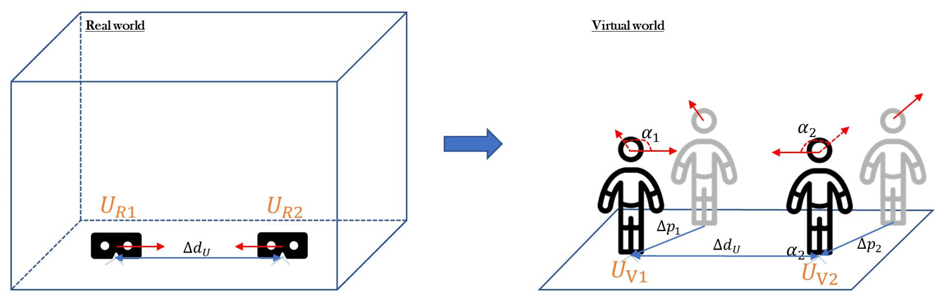
For the calibration, we position the HMD of each user on the floor at their corresponding , rotated in the direction that is set with . An illustration of the calibration process can be seen in Figure 1. Then, we manually start the calibration process.
Let be the virtual starting point of the user and the pose we want the user aligned with. We define the position and rotation of the virtual user with & . We then determine the amount we have to rotate the user () and the amount we have to move the user () with the following formula:
In the setup used in our evaluation experiment described in Section 4, the reference points of two users were positioned one meter apart from each other, with the HMDs rotated to look at each other. However, reference points can be set at arbitrary distances, as long as their relative poses in the physical world correspond to those in the virtual environment.
3.2. Marker-Based Calibration
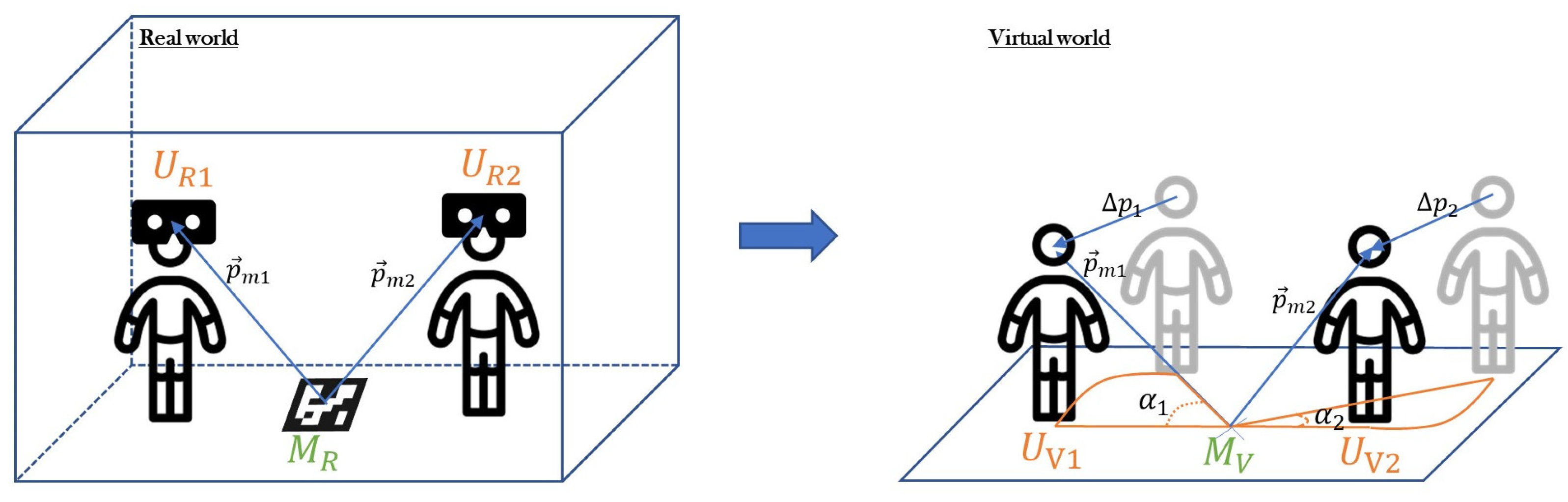
Our implementation of the marker-based calibration method uses an ArUco marker placed on the floor in the tracking space as a spatial anchor for the colocated HMDs. We used a ZED mini AR camera that we attached to Oculus Quest to detect the ArUco marker. However, HMDs front-facing cameras could be used as well, as long as their video feed can be made accessible to the developer. Using the OpenCV framework, we calculate the position and rotation of the detected marker in camera space to recalculate the position and rotation of the camera in the coordinate frame associated with the marker.
This marker also has a reference representation in the virtual world. This representation is our virtual anchor from which we are relocating our users.
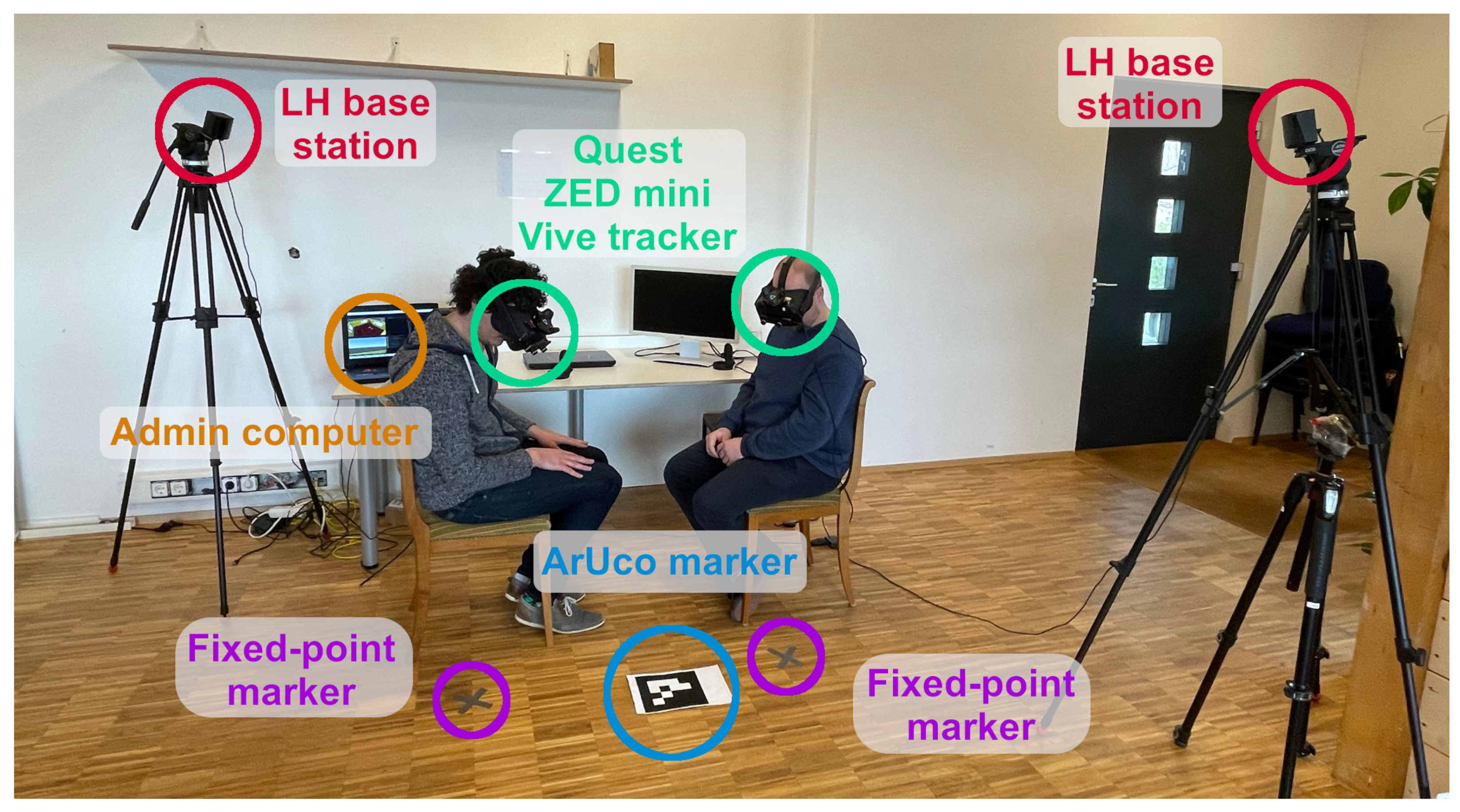
Opposed to the fixed-point calibration, where is known as the location we want to be aligned with, in marker-based calibration, we have to calculate this pose after a marker was detected. Since we know the markers world space pose () in the virtual world, we can determine the world space location () to which we want to align our user. The marker recognition software provides us with the marker location in the user’s camera space. This can be inversed to determine the user’s location in marker space (we define this with ). We now are able to determine with . Since we now know , we are able to relocate the virtual user to this location using Formula (1). An illustration of the calibration process can be found in Figure 2. Figure 8 shows this setup in the real world.
This calibration can be used for each user independently or simultaneously. The process is either triggered by pressing a button on a controller or, in our case, from an admin computer. This way, it can be controlled and easily redone during the experiment, as long as the marker is in sight of the AR camera.
3.3. Hand Tracking-Based Calibration
Our novel calibration method based on hand tracking of colocated users requires a hand tracking-capable device. We worked with Oculus Quest in our implementation; however, an additional sensor such as a LeapMotion device attached to the HMD could be used.
To see whether it makes a difference in accuracy or effort, we implemented two recalibration methods with hand tracking. The first one uses one tracked hand (here the right one) to relocate the user according to the tracked pose. The second one relocates the user by tracking both hands and calculating a mean pose to which the user is reoriented.
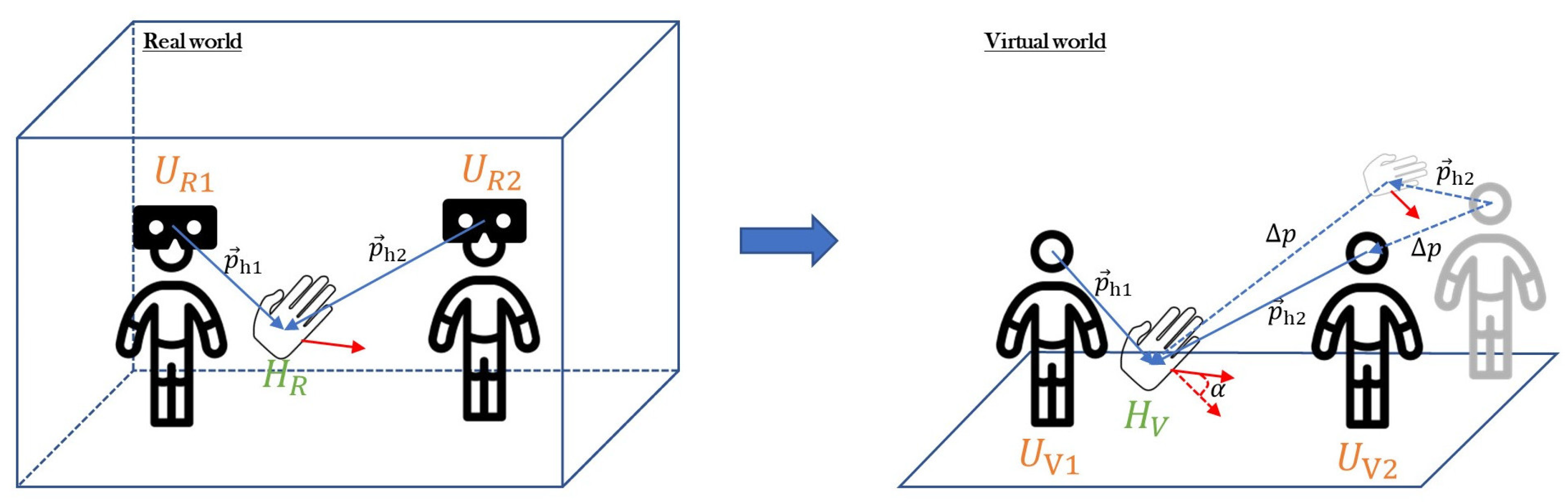
During the calibration process, one user’s hands are held behind their back to prevent the headsets from accidentally tracking these hands. The other user is then holding their right hand (respectively both hands) in front of both headsets, so both track it. If this is the case, the colocation process can be triggered by pressing a button. The calculations for that are found in Formula (2). In our setup, an admin computer is triggering the colocation process. Nevertheless, in future implementations, this could also be done by one of the users.
Then, one user sends the position and rotation of their hand anchor to the other user as a reference point. For one hand, this is the tracked hand pose; for both hands, it is a mean pose of both tracked hands. The receiving user then reorients his virtual hand to match the received pose. The whole user is then reoriented by the difference between its own and the received hand pose:
In this method, is the amount we move the user’s position and the amount we rotate the user to get them to the location . Figure 3 illustrates the reorientation process. is the location we want to set the users to in the virtual world.
From now on, the users are colocated. Depending on the HMDs tracking accuracy, this reorientation can be redone every time the headsets’ drift gets too big. Since it does not require any preparation in the real world, this can be done anytime and anywhere during application. The only requirement is that the reference hand is visible for both users. Compared to the other methods, not all users are repositioned to a new virtual location. Since one user’s hand is sent as a reference to other users, this user does not need to get reoriented because other users are relocated to match the reference position.
Variant Based on the Tracking of Two Hands
The reorientation method, when using two hands, is similar to the method which uses one hand. However, instead of using one hand’s pose as a reference, a mean point of both tracked hands is used. This point is determined by calculating the mean of each tracked hands’ position and rotation with linear interpolating the locations by half. This interpolation uses the following formula, where is the mean point and and are the virtual points for the detected left and right hand:
This formula is used for getting the mean of the position as well as the rotation. The mean is then used as a single reference point when recalibrating the user.
4. Evaluation
The aim of our evaluation is to assess the usability of each of four presented calibration methods in terms of calibration accuracy, difficulty of setup, and the need of additional hardware. Our four calibration methods are clearly distinct with respect to calibration effort and the need of additional hardware and software. We conducted an experiment to evaluate the accuracy of each method. While this experiment comprises a first technical evaluation, we plan to conduct a user-centered evaluation with multiple participants as part of our future work (Due to the COVID-19 pandemic, an extensive usability study with multiple users was not feasible at this stage.).
4.1. Evaluation Design
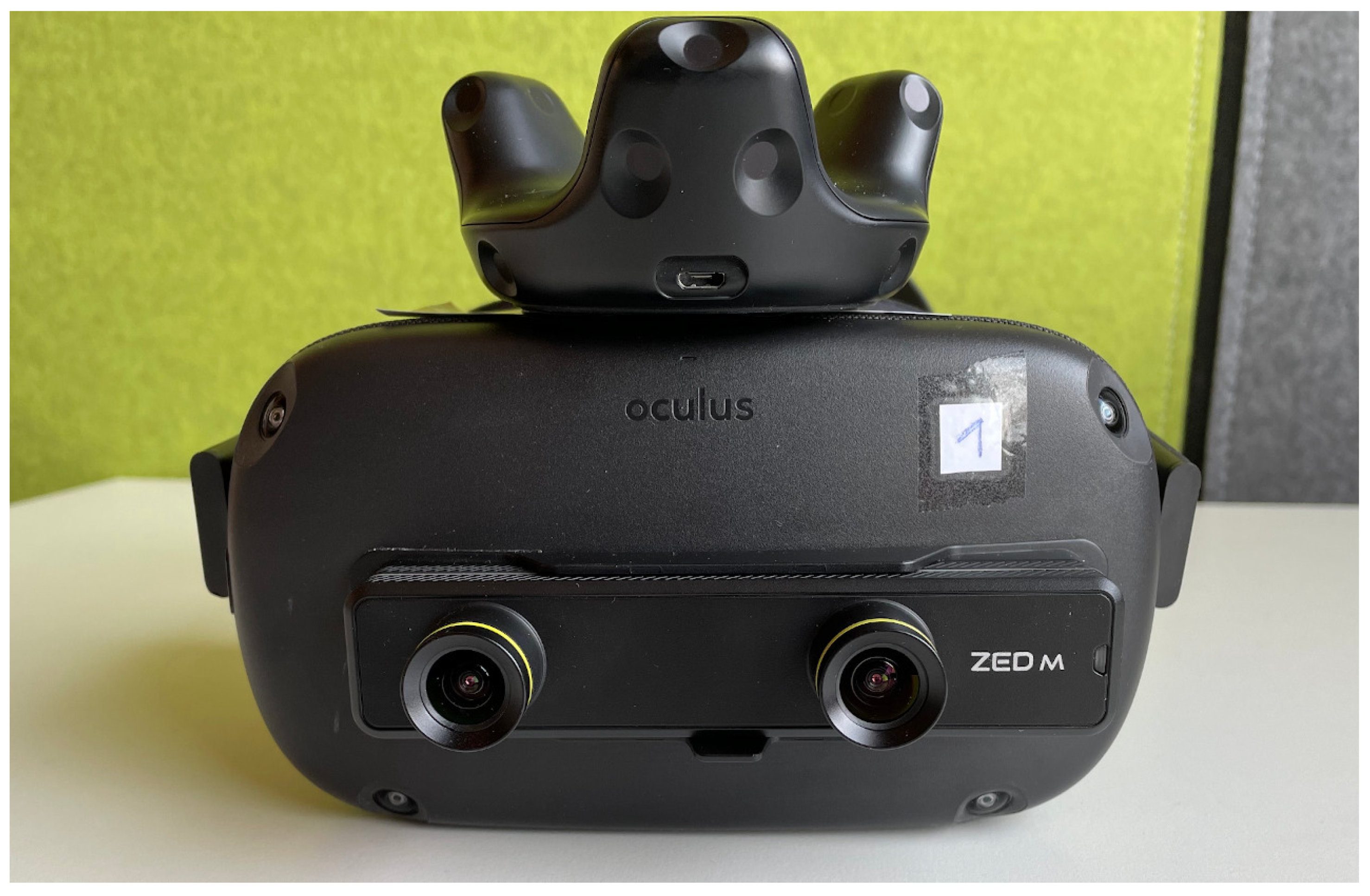
The evaluation was conducted with two HMDs (Oculus Quest) colocated within the same room and calibrated with each of the described methods. To estimate the precision of the calibration, we used ground-truth tracking data obtained with an externally mounted Lighthouse 2.0 tracking system. An HTC Vive tracker was attached to each HMD (pictured in Figure 4), allowing the ground-truth distance between both HMDs in the frame t to be calculated as the distance between two trackers, adjusted by offset between the center of the tracker and the center of the HMD. The calibrated distance between the HMDs in the frame t was calculated as the difference between their positions in the virtual scene. The difference between and provides the final distance error in the frame t as described by Formula (4):
It is worth noting that contains possible contributions due to imprecision or drift of the in-built SLAM-based tracking of Oculus Quest as well as the influence of tracking errors inherent to the Lighthouse tracking system used as a ground-truth reference. Although the Lighthouse system is not a usual first choice for collecting ground-truth measurements, tracking accuracy of a Vive tracker delivered by the Lighthouse system has been shown to be in the millimeter range with high reproducibility of position measurements [21,22]. In comparison, the tracking accuracy of Oculus Quest was measured at the level below 1 cm in good lighting conditions [23]. These results motivate our use of the Lighthouse system as the source of ground-truth tracking data, as we believe its accuracy is sufficient to allow the comparison of the investigated calibration methods. To minimize the impact of these tracking errors, we calculate for a number of frames after each calibration.
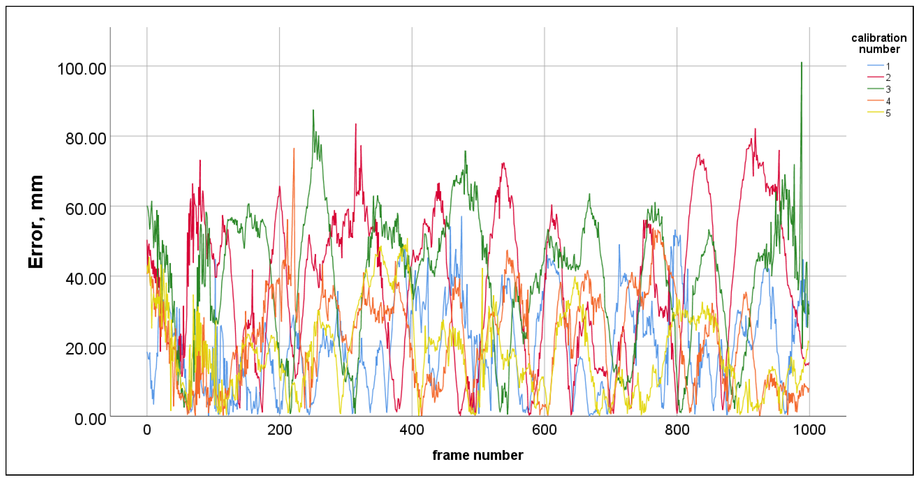
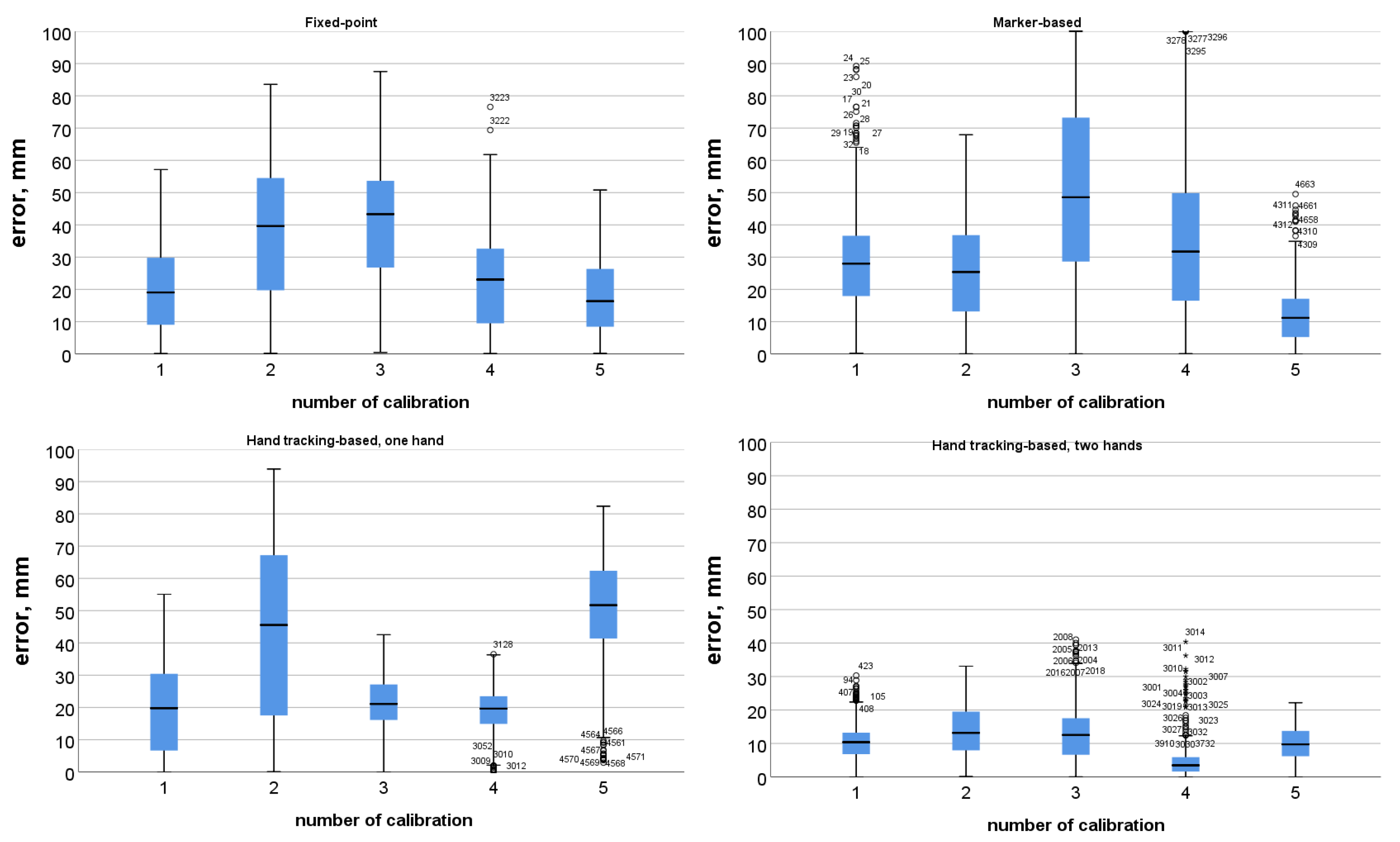
We collected pilot evaluation data, performing the calibration five times for each calibration method and calculating the distance error in consecutive frames after each calibration. These pilot recordings showed that, for each calibration method, the calculated error of the distance between two HMDs is not correlated with time. An example of time distribution of the distance error can be seen in Figure 5. Furthermore, for each method, median distance error was different for different calibration events. This fact was established with a Friedman’s ANOVA repeated-measures non-parametric test for each calibration method, since all error distributions were not normal (The details of this pilot analysis can be found in supplementary materials). Box-plots of distance error obtained from the pilot recording are presented in Figure 6. The box-plots indicate a considerable number of outliers in the distance error distributions. We are inclined to think that these outliers are the result of tracking inaccuracy in individual frames during the recording sessions. However, our method does not allow for distinguishing between contributions of possible inaccuracy of the SLAM-based tracking of Oculus Quest and the Lighthouse system.
The pilot analysis shows that neither of the investigated methods provide consistent calibration performance across different calibration attempts. For the fixed-point method, the inconsistency in the calibration results can be readily explained by the inconsistency of precision with which users place the HMDs on predefined calibration positions. For the remaining methods, calibration success directly depends on the precision of the various tracking data (of marker or users’ hands) in the frame where the calibration took place. This dependency on the precision of the tracking data used in a calibration method could be addressed in future modification to the calibration methods, however potentially at the cost of additional setup effort on the part of the users. We will discuss potential mitigation strategies in Section 5. To address the impact of the varied imprecision of every individual calibration, as well as to eliminate the impact of outliers present in the measurement of the distance error, we chose to perform each type of calibration multiple times and to record the distance error in a large number of frames after each calibration. We will then compare median distance errors resulting from each calibration. We will further use the term calibration error to refer to the median distance error calculated from the recorded distance data after each calibration.
4.2. Experimental Setup and Procedure
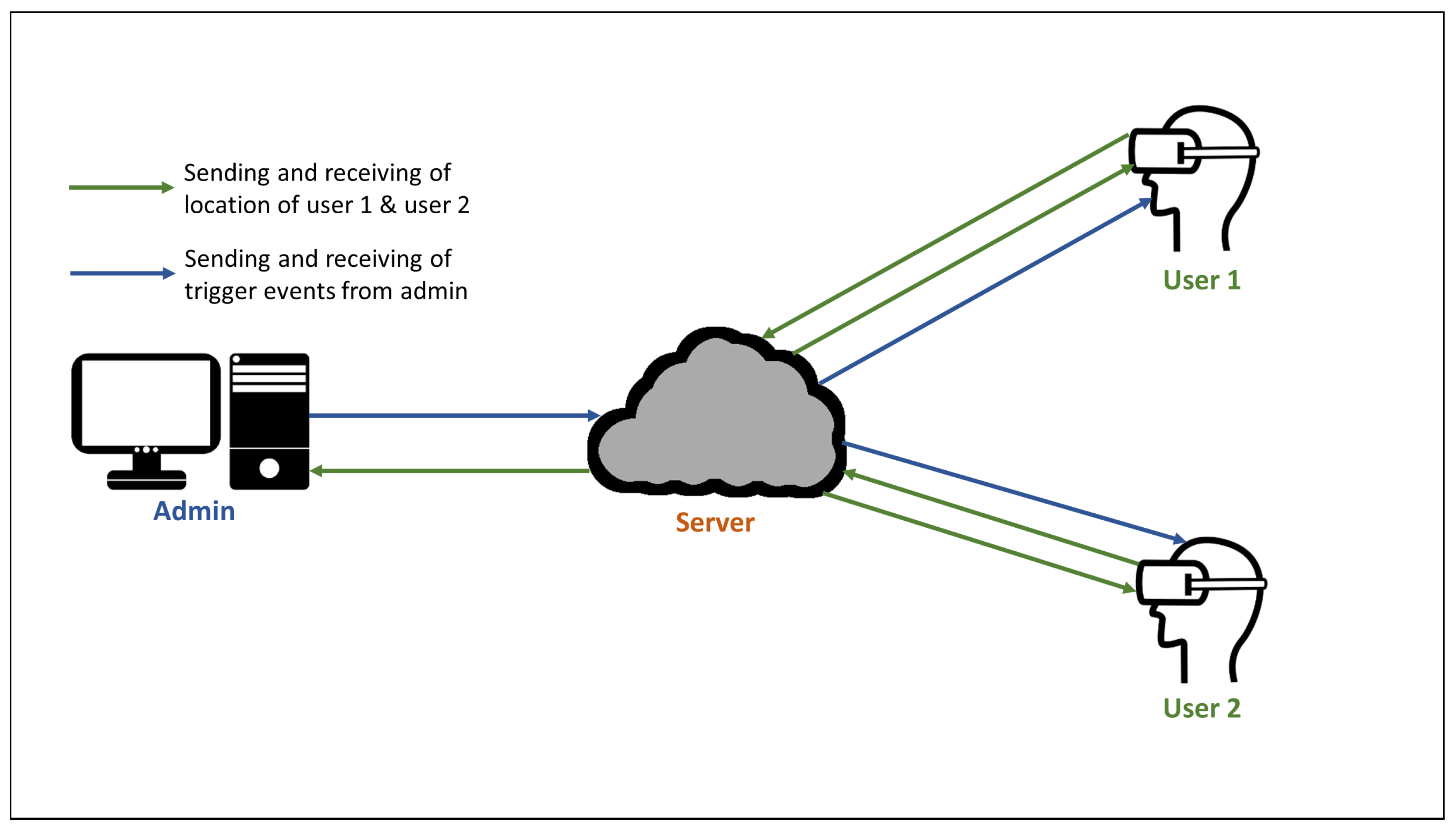
A distributed VR application run in the experiment is developed with Unity 3D (v.2019.4.3), with the networking layer built on the basis of Photon Unity Plugin (PUN). The networking layer insured the synchronization of poses obtained with input tracking data and the simultaneous execution of experimental commands on all machines. Oculus Integration asset for Unity 3D was used as an API layer providing tracked head and hand poses of Oculus Quest to each Unity3D client application. However, rendering of tracked user hands was achieved with the help of an in-house developed framework that provides a universal layer for collecting and distributing hand tracking data obtained from any input source. In the experiment, both client applications running on Oculus Quest were connected to a server, also running an administrative client issuing experimental commands. All poses of VR-immersed users as well as calibration-specific tracking data (of the tracked marker or tracked hands) are visible on the administrative client. The main command issued by the administrative client triggers the calibration procedure for a selected calibration method. A diagram illustrating the communication flow between the administrative client and Oculus Quest clients is presented in Figure 7.
The evaluation data were collected with the following experimental procedure:
- Start the administrative client that is also the master client (host) in the PUN distribution pipeline, to open the network connection.
- Connect both HMDs with respective connected Vive trackers.
- Ensure correct synchronization and assignments of HMDs and Vive trackers in the administration client.
- Collect data following the procedure detailed in Section 4.1.
To enable the marker-based calibration methods, we attached a ZED-Mini camera to each HMD as demonstrated in Figure 4. Figure 8 illustrates our room-scale experimental setup. When users connected to the same distributed application, they were able to see each other in the same virtual environment, although their relative positions did not coincide with those in the real room before the calibration. After the calibration procedure was triggered from the administrative client, users’ relative positions in the virtual environments were moved to coincide to their relative positions in the physical environment and recording of their poses started. Although the evaluation was conducted with two colocated users, the calibration procedure accommodates an arbitrary number of users.
4.3. Results
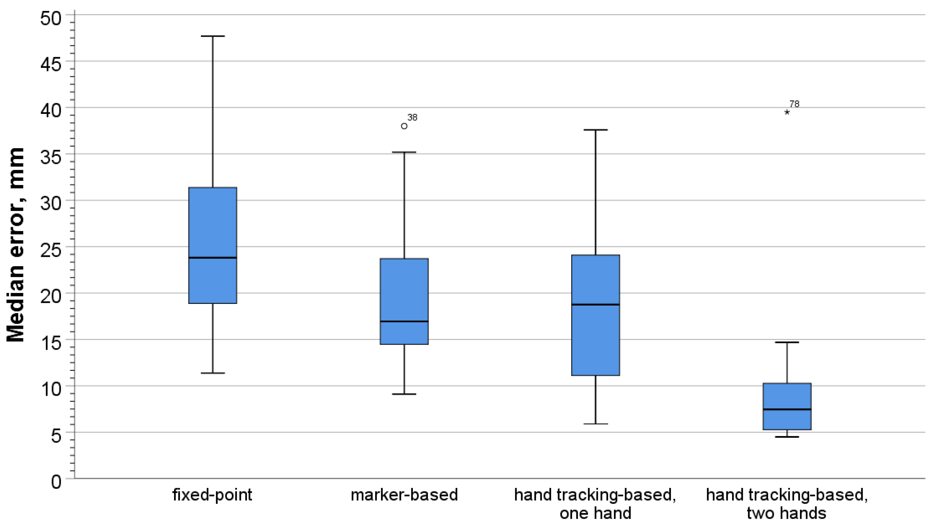
Data used in the evaluation were collected following the approach described in Section 4.1. For each method, the calibration was performed 25 times; the error between the ground-truth distance between the HMDs and the distance derived from the calibrated positions was recorded during 1000 frames after each calibration. We then calculated the median error for each dataset of 1000 error values, obtaining four datasets of median errors with 25 entries in each. The box-plots of these four datasets are presented in Figure 9. The median errors proved to be normally distributed in the Shapiro–Wilk test [24] after two outliers had been removed (p = 0.055 for the fixed-point method, p = 0.102 for the marker-based method, p = 0.221 for the hand tracking-based method with one hand, and p = 0.066 for the hand tracking-based method with two hands). The removed outliers can be seen in Figure 9, one in the marked-based method and one in the hand tracking-based method with two hands. We then used one-way ANOVA [25] to compare the distributions’ means. The analysis was performed with IBM SPSS Statistics.
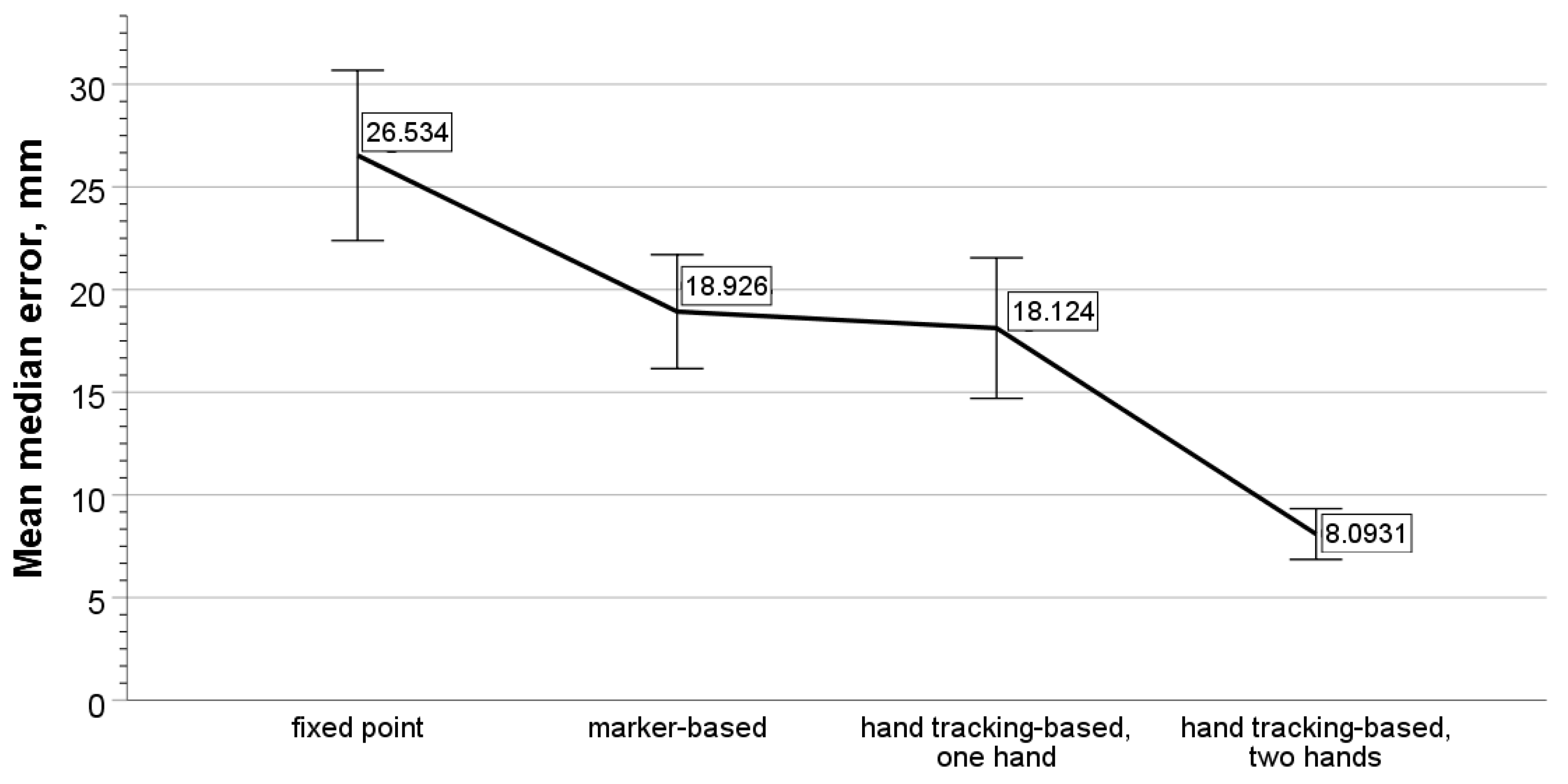
Levene’s test [26] showed a violation of the homogeneity of variance (p < 0.001). Therefore, we used Welch’s test [27] for the main analysis and the Games–Powel test for post-hoc comparisons. The median error differed significantly with different calibration methods (Welch’s F(3, 46.765) = 40.965, p < 0.001 ). The resulting plot of mean values is presented in Figure 10. Post-hoc analysis revealed that the median error was significantly larger for the fixed-point method than for all other methods. The median error of the hand tracking-based method with two hands was significantly smaller compared to all other methods. The details of post-hoc comparisons are summarized in Table 1. Mean differences are reported as significant at a 0.05 level.
5. Discussion
The results of our evaluation show that the fixed-point calibration method proved to have the largest median calibration error, whereas the hand tracking-based method provided the most accurate calibration when the variant based on the tracking of two user hands was used. The accuracy results of the marker-based method and hand tracking-based method using one user hand are comparable, with their accuracy being higher than that of the fixed-point method but lower than those of the hand tracking-based method using two hands. In this section, we discuss these results and elaborate on further important properties of the evaluated calibration methods for colocated SLAM-tracked HMDs.
5.1. Consistency and Potential for Improvement
Consistency of the calibration result describes the extent to which each calibration method delivers similar calibration accuracy when the user performs identical actions to calibrate the colocated HMDs. At the pilot evaluation stage, we discovered that the median distance error measured after each calibration proved to be different for all evaluated methods. Data of 25 calibrations for each discussed method allow us to have a more detailed look at the method’s calibration consistency.
The fixed-point calibration method showed the greatest variability among the four evaluated methods demonstrated by the largest span of median error values and their interquartile range (Figure 9). This result is somewhat expected, given that each user needs to manually place their HMD at the marked spot to calibrate for a colocated scenario. It is hardly possible for users to achieve placement accuracy in the sub-cm range. The accuracy and possibly consistency of the fixed-point method could be improved by a two-point calibration procedure suggested by McGill et al. [8].
For the marker-based calibration method, the accuracy of each individual calibration is contingent on the accuracy of marker tracking in the frame where the calibration takes place. Compared to a fixed-point and hand tracking-based calibration with one hand, this method shows a smaller interquartile range and span of median errors, indicating a better consistency than these two methods. Since the tracking process uses RGB images, its accuracy can be highly dependent on lighting conditions and varied in unstable lighting. A possible solution to mitigate the shortcomings of marker tracking is to collect marker pose data for several frames and use the averaged pose value in the calibration procedure. However, balanced values of frames need to be found since users would need to be very still during the marker pose collection time. Alternatively, a larger number of markers could be used in the calibration procedure, with the mean camera pose being calculated with the tracking data of all markers (similarly to the multi-marker tracking method used by Podkosova et al. [3]).
For hand tracking-based calibration using only one hand, the interquartile range and median error range are comparable to the fixed-point calibration range, showing much larger variability in distance error data compared to the setup when two tracked hands are used in the calibration process. This stark difference in the variability of error between the variants based on tracking of one hand and two hands might be an indication of the advantage of using multiple spatial anchors in the calibration process.
The hand tracking-based calibration method demonstrated the strongest consistency when two tracked hands were used in the calibration process. The increased consistency compared to the other tested methods is reflected in the much more compact span of the median error values and their interquartile range (Figure 9). According to our evaluation, the greater accuracy of this method combined with the clearly better consistency and the ease of execution on the part of the users makes it the best method for calibrating two-user colocated scenarios.
5.2. Ease of Setup
The fixed-point calibration method does not require any additional hardware. It also means that no additional software or plug-ins are required for developers, making this method usable by a wide range of HMDs. However, the execution of the fixed-point calibration requires certain involvement on the part of users as they need to take place (or place their HMDs) at predefined locations as accurately as possible. Moreover, if recalibration is necessary during the application runtime, users would have to remove their HMDs to ensure that their positions in the tracking space are accurate.
Marker-based calibration might require additional hardware and software, depending on whether the HMD has integrated cameras that can be accessed to enable marker tracking or whether an external camera needs to be used, as in our evaluation. The use of marker tracking itself requires additional implementation. For users, however, the execution of marker-based calibration does not present any difficulty since users only need to position themselves in a way that allows the calibration marker to be seen in the camera image. When recalibrating, users need to return to the marker, making calibration and recalibration dependent on the location of the real-world marker. The calibration process can be made even easier for users if continuous tracking is used and markers are attached directly to each user, as in the work of DeFanti et al. [10].
The hand tracking-based calibration method has similar hardware requirements as the marker-based calibration. Either an HMD with integrated hand tracking (for example, Oculus Quest) or an external sensor (for example, Leap Motion) is needed. For both cases, the developer needs to implement the hand tracking detection (i.e., use the tracking systems SDK). Since integrated hand tracking is becoming more ubiquitous, this calibration method can be used on more and more HMDs without requiring additional hardware. For preparation and calibration effort, this method shows to be the least demanding among the evaluated methods. Neither a physical marker nor a fixed location has to be set in the real world. The only requirement is that the hands of one user need to be simultaneously visible to both users. For recalibration, the users do not need to return to a specific spot in the real world. Still, they have to be near each other enough so that the reference hand is visible to both tracking systems.
5.3. Scalability
In our evaluation, two users were colocated in the same physical environment. However, each of the tested methods is designed to work for an arbitrary amount of users. In the following, we briefly discuss how the applicability of each method extends to larger amounts of colocated users.
The fixed-point calibration method can be easily extended to accommodate any amount of users. A corresponding number of marked positions in the physical environment and their counterpart target positions in the virtual environment need to be prepared to extend the method. Although such preparations would require additional involvement from an application developer, the calibration difficulty for users will remain unchanged.
For the marker-based calibration method, there might be an upper limit on the amount of participating users since HMDs (or cameras attached to them) of all users would need to track the calibration marker simultaneously. However, this limit would be rather large—it should be possible for up to ten users to stand in a circle so that the calibration marker can be tracked in all client applications. Such a limit on the amount of user HMDs that can be calibrated simultaneously would most probably be larger than the number of users that can be physically colocated in a regularly-sized tracking room. For larger tracking spaces that many users share, several markers with known offsets could be arranged to calibrate sub-groups of users.
As with the marker-based calibration method, the hand tracking-based method could have an upper limit on the amount of participating users. For a successful calibration, the reference hand needs to be tracked simultaneously in all client applications. The range of hand tracking limits the number of possible user positions from which the reference hand can be tracked. The exact scale of this limitation needs to be examined in future work. For a larger amount of users, hand tracking-based calibration could be separated into multiple calibration steps. Users’ poses could be calibrated to the same reference hand one after another until all users are correctly colocated in the virtual environment.
5.4. Applicability and Future of Hand Tracking-Based Calibration
Currently, the Oculus Quest is not designed to be used in colocated scenarios. This argument can be supported by the absence of access to the internal tracking map, making the colocation calibration necessary in the first place. Its hand tracking-enabled interaction input is not designed to be used in colocated scenarios either, the possibility of tracking hands of users not wearing the Oculus Quest device itself clearly being an artifact. It is this artifact that allowed us to use hand tracking for colocation calibration.
It is conceivable that, in the future, neural net training used to enable hand tracking on HMDs with forward-facing cameras would be implemented in a way preventing the hands of other users from being tracked (for example, by taking arm poses into account during the training stage). In this case, a direct use of hand tracking for colocation calibration would not be possible.
However, hand tracking capabilities of HMDs equipped with frontal cameras can be extended to track hands of other users deliberately, even if colocated users are relatively far away in the common walkable area. Such extension could be helpful in providing hand pose (and possibly derived full-body pose) estimations in situations where a user does not keep their hands in front of their head (for example, when the user’s arms are kept down, alongside the body). If such augmentations to hand tracking are developed, they can prove beneficial for colocation calibration, potentially proving increased accuracy. Mutual tracking is a promising direction of future work on colocated VR environments overall.
5.5. Colocation in Seated VR Scenarios
The applicability of all four discussed calibration methods is not limited to room-scale scenarios. Seated colocated VR experiences enabled by SLAM-tracked HMDs also require calibration. Colocation in seated VR can be used in a number of scenarios. For example, it can enable a meeting scenario where several participants are sitting at the same table. A calibration method will ensure that the virtual environment and all users are synchronized, allowing them to view and interact with the same 3D model or visualized data.
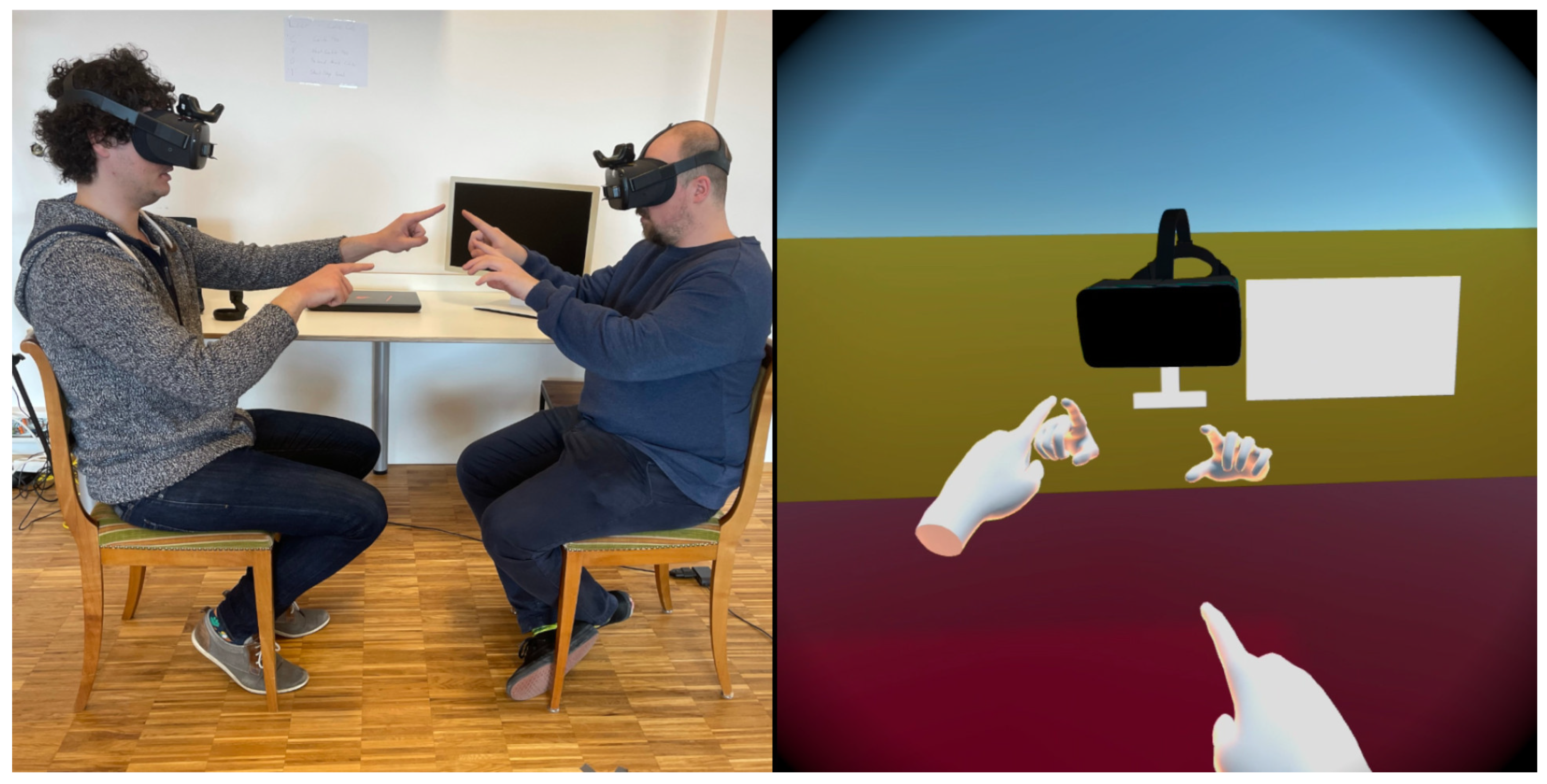
Likewise, the discussed calibration methods can be used for seated collaborative VR experiences in CAVE environments [9], where users are positioned on physical seats aligned to virtual seats. Currently, the alignment is ensured manually by measuring the poses of the physical seats in the CAVE space. This alignment can be automatized by using a calibration procedure with an AR marker or hand tracking for more flexible scenarios. Figure 11 shows two seated users after being colocated interacting with their hands.
6. Conclusions
The research presented in this paper investigated three calibration methods that enable shared colocated VR scenarios for SLAM-tracked HMDs. We implemented and experimentally evaluated fixed-point calibration, marker-based calibration, and our novel calibration method that uses hand tracking data of colocated users as spatial anchors. Our experimental evaluation showed that hand tracking-based calibration using two user hands as anchors achieved the highest consistent accuracy compared to fixed-point and marker-based calibration. Not requiring any internal infrastructure and being easy to execute at any time in a colocated scenario, our hand tracking-based calibration method proved to be very advantageous. With the current trend of hand tracking being adopted by HMD manufacturers, this calibration method provides great potential for a wide range of VR solutions. Since the setup is easy to use for end-users, we hope that this encourages developers to implement colocation into end-user VR applications further. In future applications, it would be interesting to extend the methods to more than two users. A limitation of concurrent users and the impact of interference of all users and VR systems could be examined. A tracking system designed to track users’ hands mutually could improve the user experience in colocated scenarios and be promising research. With this approach, the impact of view-direction when tracking hands on calibration results is a promising topic of investigation. Finally, we plan to conduct a usability evaluation investigating acceptance of the methods and factors affecting the user experience as the next step of our future research, building upon the presented results.
Supplementary Materials
The following are available online at https://0-www-mdpi-com.brum.beds.ac.uk/article/10.3390/computers10050058/s1.
Author Contributions
The authors in this research contributed to this article with the following: Conceptualization, D.R. and I.P.; methodology, D.R. and I.P.; software, D.R.; validation, D.R.; formal analysis, D.R. and I.P.; investigation, D.R.; data curation, D.R.; writing—original draft preparation, D.R.; writing—review and editing, D.R., I.P., H.K., and D.S.; visualization, D.R.; supervision, H.K. and D.S.; project administration, D.R. All authors have read and agreed to the published version of the manuscript.
Funding
The authors acknowledge TU Wien Bibliothek for financial support through its Open Access Funding Program.
Informed Consent Statement
Informed consent was obtained from all subjects involved in the study.
Data Availability Statement
The data presented in this study are available in the supplementary material.
Acknowledgments
Open Access Funding by TU Wien.
Conflicts of Interest
The authors declare no conflict of interest.
Abbreviations
The following abbreviations are used in this manuscript:
| VR | Virtual Reality |
| HMD | Head-Mounted Display |
| SLAM | Simultaneous Localization and Mapping |
| DOF | Degrees of Freedom |
References
- Shi, Y.; Du, J.; Lavy, S.; Zhao, D. A Multiuser Shared Virtual Environment for Facility Management. Procedia Eng. 2016, 145, 120–127. [Google Scholar] [CrossRef] [Green Version]
- Podkosova, I. Walkable Multi-User VR: Effects of Physical and Virtual Colocation. Ph.D. Thesis, Research Unit of Computer Graphics, Institute of Visual Computing and Human-Centered Technology, Faculty of Informatics, TU Wien, Favoritenstrasse 9-11/E193-02, Vienna, Austria, 2019. [Google Scholar]
- Podkosova, I.; Vasylevska, K.; Schoenauer, C.; Vonach, E.; Fikar, P.; Bronederk, E.; Kaufmann, H. Immersivedeck: A large-scale wireless VR system for multiple users. In Proceedings of the 2016 IEEE 9th Workshop on Software Engineering and Architectures for Realtime Interactive Systems (SEARIS), Greenville, SC, USA, 20–20 March 2016; pp. 1–7. [Google Scholar] [CrossRef]
- Furtado, J.S.; Liu, H.H.T.; Lai, G.; Lacheray, H.; Desouza-Coelho, J. Comparative Analysis of OptiTrack Motion Capture Systems. In Advances in Motion Sensing and Control for Robotic Applications; Janabi-Sharifi, F., Melek, W., Eds.; Springer International Publishing: Cham, Switzerland, 2019; pp. 15–31. [Google Scholar]
- Taketomi, T.; Uchiyama, H.; Ikeda, S. Visual SLAM algorithms: A survey from 2010 to 2016. IPSJ Trans. Comput. Vis. Appl. 2017, 9. [Google Scholar] [CrossRef]
- He, Z.; Du, R.; Perlin, K. CollaboVR: A Reconfigurable Framework for Creative Collaboration in Virtual Reality. In Proceedings of the 2020 IEEE International Symposium on Mixed and Augmented Reality (ISMAR), Porto de Galinhas, Brazil, 9–13 November 2020; pp. 542–554. [Google Scholar] [CrossRef]
- Niehorster, D.; Li, L.; Lappe, M. The Accuracy and Precision of Position and Orientation Tracking in the HTC Vive Virtual Reality System for Scientific Research. i-Perception 2017, 8. [Google Scholar] [CrossRef] [PubMed] [Green Version]
- McGill, M.; Gugenheimer, J.; Freeman, E. A Quest for Co-Located Mixed Reality: Aligning and Assessing SLAM Tracking for Same-Space Multi-User Experiences. In Proceedings of the 26th ACM Symposium on Virtual Reality Software and Technology; VRST’20; Association for Computing Machinery: New York, NY, USA, 2020. [Google Scholar] [CrossRef]
- Layng, K.; Perlin, K.; Herscher, S.; Brenner, C.; Meduri, T. Cave: Making Collective Virtual Narrative. In ACM SIGGRAPH 2019 Art Gallery; SIGGRAPH’19; Association for Computing Machinery: New York, NY, USA, 2019. [Google Scholar] [CrossRef]
- DeFanti, C.; Geiger, D.; Panozzo, D. Co-Located Augmented and Virtual Reality Systems. Ph.D. Thesis, New York University, New York, NY, USA, 2019. [Google Scholar]
- Weissker, T.; Tornow, P.; Froehlich, B. Tracking Multiple Collocated HTC Vive Setups in a Common Coordinate System. In Proceedings of the 2020 IEEE Conference on Virtual Reality and 3D User Interfaces Abstracts and Workshops (VRW), Atlanta, GA, USA, 22–26 March 2020; pp. 592–593. [Google Scholar] [CrossRef]
- Fox, D.; Ko, J.; Konolige, K.; Limketkai, B.; Schulz, D.; Stewart, B. Distributed Multirobot Exploration and Mapping. Proc. IEEE 2006, 94, 1325–1339. [Google Scholar] [CrossRef]
- Herscher, S.; DeFanti, C.; Vitovitch, N.G.; Brenner, C.; Xia, H.; Layng, K.; Perlin, K. CAVRN: An Exploration and Evaluation of a Collective Audience Virtual Reality Nexus Experience. In Proceedings of the 32nd Annual ACM Symposium on User Interface Software and Technology; UIST’19; Association for Computing Machinery: New York, NY, USA, 2019; pp. 1137–1150. [Google Scholar] [CrossRef]
- Zimmerman, T.G.; Lanier, J.; Blanchard, C.; Bryson, S.; Harvill, Y. A Hand Gesture Interface Device. SIGCHI Bull. 1986, 17, 189–192. [Google Scholar] [CrossRef]
- Kessler, G.; Walker, N.; Hodges, L. Evaluation of the CyberGlove(TM) as a Whole Hand Input Device. ACM Trans. Comput. Hum. Interact. 1995, 2. [Google Scholar] [CrossRef]
- Temoche, P.; Ramirez, E.; Rodríguez, O. A Low-cost Data Glove for Virtual Reality. 2012. pp. TCG 31–36. Available online: http://citeseerx.ist.psu.edu/viewdoc/download?rep=rep1&type=pdf&doi=10.1.1.226.1554 (accessed on 31 March 2021).
- Kortier, H.; Schepers, M.; Sluiter, V.; Veltink, P.; Leardini, A.; Stagni, R. Ambulatory assesment of hand kinematics: Using an instrumented glove. In Computer Standards & Interfaces—CSI; Universita di Bologna: Bologna, Italy, 2012. [Google Scholar]
- Hammer, J.H.; Beyerer, J. Robust Hand Tracking in Realtime Using a Single Head-Mounted RGB Camera. In Human-Computer Interaction. Interaction Modalities and Techniques; Kurosu, M., Ed.; Springer: Berlin/Heidelberg, Germany, 2013; pp. 252–261. [Google Scholar]
- Bachmann, D.; Weichert, F.; Rinkenauer, G. Evaluation of the Leap Motion Controller as a New Contact-Free Pointing Device. Sensors 2014, 15, 214–233. [Google Scholar] [CrossRef] [PubMed] [Green Version]
- Weichert, F.; Bachmann, D.; Rudak, B.; Fisseler, D. Analysis of the Accuracy and Robustness of the Leap Motion Controller. Sensors 2013, 13, 6380–6393. [Google Scholar] [CrossRef] [PubMed] [Green Version]
- Bauer, P.; Lienhart, W.; Jost, S. Accuracy Investigation of the Pose Determination of a VR System. Sensors 2021, 21, 1622. [Google Scholar] [CrossRef] [PubMed]
- Borges, M.; Symington, A.; Coltin, B.; Smith, T.; Ventura, R. HTC Vive: Analysis and Accuracy Improvement. In Proceedings of the 2018 IEEE/RSJ International Conference on Intelligent Robots and Systems (IROS), Madrid, Spain, 1–5 October 2018; pp. 2610–2615. [Google Scholar] [CrossRef]
- Passos, D.; Jung, B. Measuring the Accuracy of Inside-Out Tracking in XR Devices Using a High-Precision Robotic Arm. In Proceedings of the HCI International 2020—Posters, Copenhagen, Denmark, 19–24 July 2020; pp. 19–26. [Google Scholar] [CrossRef]
- Shapiro, S.S.; Wilk, M.B. An Analysis of Variance Test for Normality (Complete Samples). Biometrika 1965, 52, 591–611. [Google Scholar] [CrossRef]
- Ostertagova, E.; Ostertag, O. Methodology and Application of One-way ANOVA. Am. J. Mech. Eng. 2013, 1, 256–261. [Google Scholar] [CrossRef]
- Levene, H. Robust Tests for Equality of Variance. In Contributions to Probability and Statistics; Stanford University Press: Palo Alto, CA, USA, 1960; Volume 2, pp. 278–292. [Google Scholar]
- Welch, B.L. The generalisation of student’s problems when several different population variances are involved. Biometrika 1947, 34, 28–35. [Google Scholar] [CrossRef]
Figure 1.
(Left): The users’ headsets are positioned on predefined locations in the real world; (Right): virtual users who are repositioned to , which is the virtual representation of . The distance is the same in the real and virtual world. Red arrows represent the view direction of the user.
Figure 1.
(Left): The users’ headsets are positioned on predefined locations in the real world; (Right): virtual users who are repositioned to , which is the virtual representation of . The distance is the same in the real and virtual world. Red arrows represent the view direction of the user.

Figure 2.
(Left): The users standing in the real world detecting an ARuCo marker; (Righ): virtual users who are relocated depending on the detected marker. The virtual user is moved by and rotated by to get to , which is the user’s position and rotation in marker space.
Figure 2.
(Left): The users standing in the real world detecting an ARuCo marker; (Righ): virtual users who are relocated depending on the detected marker. The virtual user is moved by and rotated by to get to , which is the user’s position and rotation in marker space.

Figure 3.
(Left): The users standing in the real world detecting the same hand; (Right): user gets relocated by difference . is the difference in rotation of the tracked own hand and received reference hand. Rotation is visualized by red arrows. Compared to other methods, only the other user gets relocated.

Figure 4.
Oculus Quest with an attached Vive Tracker and ZED-Mini camera used in the evaluation.

Figure 5.
Time distribution of the distance error, shown on the example of a dataset from fixed-point calibration.
Figure 5.
Time distribution of the distance error, shown on the example of a dataset from fixed-point calibration.

Figure 6.
Distance error box-plots of pilot recordings.

Figure 7.
Network communication between admin computer and VR users.

Figure 8.
Exemplary experiment setup for the marker-based calibration method.

Figure 9.
Box-plots of median distance error for four calibration types.

Figure 10.
Mean values of calibration error (median distance error) for each calibration method.

Figure 11.
Two seated colocated users using their hands.


Table 1.
Results of post-hoc pairwise comparisons with the Games–Powel test.
| (i) Method | (j) Method | (Mean Diff. (i–j) | std. Error | Sig. | 95% CI | |
|---|---|---|---|---|---|---|
| Lower Bound | Upper Bound | |||||
| fixed-point | marker | 7.60789 | 2.49586 | 0.02 | 0.9291 | 14.2867 |
| one hand | 8.41017 | 2.68948 | 0.016 | 1.2433 | 15.5770 | |
| two hands | 18.44063 | 2.16391 | <0.001 | 12.5353 | 24.3460 | |
| marker | fixed-point | −7.60789 | 2.49586 | 0.02 | −14.2867 | −0.9291 |
| one hand | 0.80227 | 2.20473 | 0.983 | −5.0771 | 6.6817 | |
| two hands | 10.83273 | 1.51988 | <0.001 | 6.7132 | 14.9523 | |
| one hand | fixed-point | −8.41017 | 2.68948 | 0.016 | −15.5770 | −1.2433 |
| marker | −0.80227 | 2.20473 | 0.983 | −6.6817 | 5.0771 | |
| two hands | 10.03046 | 1.82044 | <0.001 | 5.0816 | 14.9793 | |
| two hands | fixed-point | −18.44063 | 2.16391 | <0.001 | −24.3460 | −12.5353 |
| marker | −10.83273 | 1.51988 | <0.001 | −14.9523 | −6.7132 | |
| one hand | −10.03046 | 1.82044 | <0.001 | −14.9793 | −5.0816 | |
Publisher’s Note: MDPI stays neutral with regard to jurisdictional claims in published maps and institutional affiliations. |
© 2021 by the authors. Licensee MDPI, Basel, Switzerland. This article is an open access article distributed under the terms and conditions of the Creative Commons Attribution (CC BY) license (https://creativecommons.org/licenses/by/4.0/).
Share and Cite
MDPI and ACS Style
Reimer, D.; Podkosova, I.; Scherzer, D.; Kaufmann, H. Colocation for SLAM-Tracked VR Headsets with Hand Tracking. Computers 2021, 10, 58. https://0-doi-org.brum.beds.ac.uk/10.3390/computers10050058
AMA Style
Reimer D, Podkosova I, Scherzer D, Kaufmann H. Colocation for SLAM-Tracked VR Headsets with Hand Tracking. Computers. 2021; 10(5):58. https://0-doi-org.brum.beds.ac.uk/10.3390/computers10050058
Chicago/Turabian StyleReimer, Dennis, Iana Podkosova, Daniel Scherzer, and Hannes Kaufmann. 2021. "Colocation for SLAM-Tracked VR Headsets with Hand Tracking" Computers 10, no. 5: 58. https://0-doi-org.brum.beds.ac.uk/10.3390/computers10050058
Note that from the first issue of 2016, this journal uses article numbers instead of page numbers. See further details here.